Chapter 3 AWARDfi BIOS SETUPohwc.narod.ru/man-dat/mainboards/msi/ms-6153-3.pdfCHAPTER 3 AWARD ®...
38
CHAPTER 3 CHAPTER 3 CHAPTER 3 CHAPTER 3 CHAPTER 3 AWARD AWARD AWARD AWARD AWARD ® BIOS SETUP BIOS SETUP BIOS SETUP BIOS SETUP BIOS SETUP 3-1 Chapter 3 AWARD fi BIOS SETUP Award ® BIOS ROM has a built-in Setup program that allows users to modify the basic system configuration. This type of information is stored in battery-backed RAM (CMOS RAM), so that it retains the Setup information when the power is turned off.
Transcript of Chapter 3 AWARDfi BIOS SETUPohwc.narod.ru/man-dat/mainboards/msi/ms-6153-3.pdfCHAPTER 3 AWARD ®...

CHAPTER 3CHAPTER 3CHAPTER 3CHAPTER 3CHAPTER 3 AWARDAWARDAWARDAWARDAWARD® BIOS SETUP BIOS SETUP BIOS SETUP BIOS SETUP BIOS SETUP
3-1
Chapter 3
AWARD ®®®®® BIOS SETUP
Award® BIOS ROM has a built-in Setup program that allows users to modifythe basic system configuration. This type of information is stored inbattery-backed RAM (CMOS RAM), so that it retains the Setup informationwhen the power is turned off.

CHAPTER 3CHAPTER 3CHAPTER 3CHAPTER 3CHAPTER 3 AWARDAWARDAWARDAWARDAWARD® BIOS SETUP BIOS SETUP BIOS SETUP BIOS SETUP BIOS SETUP
3-2
3.1 Entering Setup3.1 Entering Setup3.1 Entering Setup3.1 Entering Setup3.1 Entering Setup
Power on the computer and press <Del> immediately to allow you toenter Setup. The other way to enter Setup is to power on the computer.When the below message appears briefly at the bottom of the screen duringthe POST (Power On Self Test), press <Del> key or simultaneously press<Ctrl>, <Alt>, and <Esc> keys.
TO ENTER SETUP BEFORE BOOT PRESS <CTRL-ALT-ESC>OR <DEL> KEY
If the message disappears before you respond and you still wish toenter Setup, restart the system to try again by turning it OFF then ON orpressing the “RESET” button on the system case. You may also restart bysimultaneously pressing <Ctrl>, <Alt>, and <Delete> keys. If you do notpress the keys at the correct time and the system does not boot, an errormessage will be displayed and you will again be asked to,
PRESS <F1> TO CONTINUE, <CTRL-ALT-ESC>OR <DEL> TO ENTER SETUP
3.2 Getting Help3.2 Getting Help3.2 Getting Help3.2 Getting Help3.2 Getting Help
Main MenuThe on-line description of the highlighted setup function is displayed
at the bottom of the screen.
Status Page Setup Menu/Option Page Setup MenuPress F1 to pop up a small help window that describes the appropri-
ate keys to use and the possible selections for the highlighted item. To exitthe Help Window press <F1> or <Esc>.

CHAPTER 3CHAPTER 3CHAPTER 3CHAPTER 3CHAPTER 3 AWARDAWARDAWARDAWARDAWARD® BIOS SETUP BIOS SETUP BIOS SETUP BIOS SETUP BIOS SETUP
3-3
3.3 The Main Menu3.3 The Main Menu3.3 The Main Menu3.3 The Main Menu3.3 The Main Menu
Once you enter Award® BIOS CMOS Setup Utility, the Main Menu (Figure 1)will appear on the screen. The Main Menu allows you to select from elevensetup functions and two exit choices. Use arrow keys to select among theitems and press <Enter> to accept or enter the sub-menu.
ROM PCI/ISA BIOS (2A59IM4C)CMOS SETUP UTILITY
AWARD SOFTWARE, INC.
STANDARD CMOS SETUP
BIOS FEATURES SETUP
CHIPSET FEATURES SETUP
POWER MANAGEMENT SETUP
PNP/PCI CONFIGURATION
LOAD SETUP DEFAULTS
<<<CPU PLUG & PLAY II>>>
INTEGRATED PERIPHERALS
SUPERVISOR PASSWORD
USER PASSWORD
IDE HDD AUTO DETECTION
SAVE & EXIT SETUP
EXIT WITHOUT SAVING
Esc : QuitF10 : Save & Exit Setup
Time, Date, Hard Disk Type...
↑ ↓ → ← : Select Item(Shift)F2 : Change Color
Standard CMOS SetupThis setup page includes all the items in a standard compatible BIOS.
BIOS Features SetupThis setup page includes all the items of Award® special enhanced
features.
CHAPTER 3CHAPTER 3CHAPTER 3CHAPTER 3CHAPTER 3 AWARDAWARDAWARDAWARDAWARD® BIOS SETUP BIOS SETUP BIOS SETUP BIOS SETUP BIOS SETUP
3-4
Chipset Features SetupThis setup page includes all the items of chipset special features.
Power Management SetupThis category determines the power consumption for system after
setting the specified items. Default value is Disable.
PNP/PCI Configuration SetupThis category specifies the IRQ level for PCI and ISA devices.
Load Setup DefaultsChipset defaults indicates the values required by the system for the
maximum performance.
CPU Plug & Play IIThis function supports CPU Plug & Play II and Special Hardware
Monitor.
Integrated PeripheralsChange, set or disable onboard I/O, IRQ, and DMA assignment.
Supervisor Password/User PasswordChange, set or disable password. This function allows the user
access to the system and setup or just setup.
IDE HDD Auto DetectionAutomatically configure hard disk parameters.
Save & Exit SetupSave CMOS value changes to CMOS and exit setup.
Exit Without SavingAbandon all CMOS value changes and exit setup.
CHAPTER 3CHAPTER 3CHAPTER 3CHAPTER 3CHAPTER 3 AWARDAWARDAWARDAWARDAWARD® BIOS SETUP BIOS SETUP BIOS SETUP BIOS SETUP BIOS SETUP
3-5
3.4 Standard CMOS Setup3.4 Standard CMOS Setup3.4 Standard CMOS Setup3.4 Standard CMOS Setup3.4 Standard CMOS Setup
The items in Standard CMOS Setup Menu are divided into 10 catego-ries. Each category includes no, one or more than one setup items. Use thearrow keys to highlight the item and then use the <PgUp> or <PgDn> keysto select the value you want in each item.
ROM PCI/ISA BIOS (2A59IM4A)STANDARD CMOS SETUP
AWARD SOFTWARE, INC.
HARD DISKS TYPE SIZE CYLS HEADS PRECOMP LANDZONE SECTORMODE
Primary Master: Auto 0 0 0 0 0 0 AUTO
Primary Slave : Auto 0 0 0 0 0 0 AUTO
Secondary Master : Auto 0 0 0 0 0 0 AUTO
Secondary Slave : Auto 0 0 0 0 0 0 AUTO
Drive A : 1.44M,3.5in. Base Memory: 640KDrive B : None Extended Base Memory:15360K
Other Memory: 384KVideo : EGA/VGAHalt On : All, but Keyboard Total Memory: 16384K
Date(mm:dd:yy): Fri, Jan 29,1999Time(hh:mm:ss): 00:00:00
ESC : Quit ↑ ↓ → ← : Select Item PU/PD/+/- : Modify
F1 : Help (Shift)F2 : Change Color
CHAPTER 3CHAPTER 3CHAPTER 3CHAPTER 3CHAPTER 3 AWARDAWARDAWARDAWARDAWARD® BIOS SETUP BIOS SETUP BIOS SETUP BIOS SETUP BIOS SETUP
3-6
DateThe date format is <day><month> <date> <year>.
Day Day of the week, from Sun to Sat, determined byBIOS. Read-only.
month The month from Jan. through Dec.date The date from 1 to 31 can be keyed by numeric
function keys.year The year, depends on the year of the BIOS
TimeThe time format is <hour> <minute> <second>.
PrimaryMaster/PrimarySlaveSecondaryMaster/Secondary Slave
These categories identify the types of 2 channels that have beeninstalled in the computer. There are 45 pre-defined types and 4 user defin-able types for Enhanced IDE BIOS. Type 1 to Type 45 are pre-defined. TypeUser is user-definable.
Press PgUp/<+> or PgDn/<-> to select a numbered hard disk type ortype the number and press <Enter>. Note that the specifications of yourdrive must match with the drive table. The hard disk will not work properly ifyou enter improper information for this category. If your hard disk drivetype is not matched or listed, you can use Type User to define your owndrive type manually.
If you select Type User, related information is asked to be entered tothe following items. Enter the information directly from the keyboard andpress <Enter>. This information should be provided in the documentationfrom your hard disk vendor or the system manufacturer.

CHAPTER 3CHAPTER 3CHAPTER 3CHAPTER 3CHAPTER 3 AWARDAWARDAWARDAWARDAWARD® BIOS SETUP BIOS SETUP BIOS SETUP BIOS SETUP BIOS SETUP
3-7
If the controller of HDD interface is ESDI, the selection shall be“Type 1”.
If the controller of HDD interface is SCSI, the selection shall be“None”.
If the controller of HDD interface is CD-ROM, the selection shall be“None”.
CYLS. number of cylindersHEADS number of headsPRECOMP write precomLANDZONE landing zoneSECTORS number of sectorsMODEHDD access mode

CHAPTER 3CHAPTER 3CHAPTER 3CHAPTER 3CHAPTER 3 AWARDAWARDAWARDAWARDAWARD® BIOS SETUP BIOS SETUP BIOS SETUP BIOS SETUP BIOS SETUP
3-8
3.5 BIOS Features Setup3.5 BIOS Features Setup3.5 BIOS Features Setup3.5 BIOS Features Setup3.5 BIOS Features Setup
ROM PCI/ISA BIOS (2A59IM4A)BIOS FEATURES SETUP
AWARD SOFTWARE, INC.
Esc : Quit ↑ ↓ → ← : Select item
F1 : Help PU/PD/+/- : modify
F5 : Old Value(Shift) F2 : Color
F6 : Load BIOS Defaults
F7 : Load Setup Defaults
Anti-Virus Protection : DisabledCPU Internal Cache : EnabledExternal Cache : EnabledCPU L2 Cache ECC Checking: EnabledQuick Power on Self Test : DisabledBoot From LAN First : DisabledBoot Sequence : A,C,SCSISwap Floppy Drive : DisabledBoot Up Floppy Seek : EnabledFloppy FIFO Control : DisabledBoot up NumLock status : OnGate A20 Option : FastSecurity Option : SetupPCI/VGA palette snoop : DisabledOS select for DRAM>64MB : Non-OS2Report No FDD For WIN 95 : Yes
Video BIOS Shadow :EnabledC8000-CBFFF Shadow :DisabledCC000-CFFFF Shadow :DisabledD0000-D3FFF Shadow :DisabledD4000-D7FFF Shadow :DisabledD8000-D8FFF Shadow :DisabledDC000-DFFFF Shadow :Disabled
Anti-Virus ProtectionDuring and after the system boots up, any attempt to write to
the boot sector or partition table of the hard disk drive will halt thesystem and the following error message will appear. For the meantime, you can run an anti-virus program to locate the problem.
Disable(default) No warning message to appear whenanything attempts to access the bootsector or hard disk partition table.
Enable Activates automatically when thesystem boots up causing a warningmessage to appear when anythingattempts to access the boot sector ofhard disk partition table.

CHAPTER 3CHAPTER 3CHAPTER 3CHAPTER 3CHAPTER 3 AWARDAWARDAWARDAWARDAWARD® BIOS SETUP BIOS SETUP BIOS SETUP BIOS SETUP BIOS SETUP
3-9
CPU Internal CacheThe default value is Enabled.Enabled (default) Enable cacheDisabled Disable cache
Note: The internal cache is built in the processor.
External CacheChoose Enabled or Disabled. This option enables the level 2 cache
memory.
CPU L2 Cache ECC CheckingChoose Enabled or Disabled. This option enables the level 2 cache
memory ECC(error check correction). Using 66MHz CPU BUS Pentium® IIprocessor, set to Enabled or Disabled. For CeleronTM processor w/o Cache,always set to Disabled.
Quick Power On Self TestThis category speeds up Power On Self Test (POST) after you power
on the computer. If this is set to Enabled, BIOS will shorten or skip somecheck items during POST.
Enabled Enable quick POSTDisabled (default) Normal POST

CHAPTER 3CHAPTER 3CHAPTER 3CHAPTER 3CHAPTER 3 AWARDAWARDAWARDAWARDAWARD® BIOS SETUP BIOS SETUP BIOS SETUP BIOS SETUP BIOS SETUP
3-10
Boot From LAN FirstDuring Enabled, if there’s a LAN card onboard, the priority from
booting will be from the LAN.
Boot SequenceThis category determines which drive the computer searches first for
the disk operating system (i.e., DOS). The settings are A,C,SCSI/C,A,SCSI/C,CD-ROM,A/CD-ROM,C,A/D,A,SCSI/E,A,SCSI/F,A,SCSI/SCSI,A,C/SCSI,C,A/C,LS/ZIP,C only. Default value is A,C,SCSI.
Swap Floppy DriveSwitches the floppy disk drives between being designated as A and
B. Default is Disabled.
Boot Up Floppy SeekDuring POST, BIOS will determine if the floppy disk drive installed is
40 or 80 tracks. 360K type is 40 tracks while 760K, 1.2M and 1.44M are all 80tracks.
Floppy FIFO ControlDuring Enabled, the FDD disk will perform better.
Boot Up NumLock StatusThe default value is On.
On (default) Keypad is numeric keys.Off Keypad is arrow keys.
Gate A20 OptionNormal The A20 signal is controlled by keyboard
controller or chipset hardware.Fast(default) The A20 signal is controlled by port 92 or
chipset specific method.

CHAPTER 3CHAPTER 3CHAPTER 3CHAPTER 3CHAPTER 3 AWARDAWARDAWARDAWARDAWARD® BIOS SETUP BIOS SETUP BIOS SETUP BIOS SETUP BIOS SETUP
3-11
Security OptionThis category allows you to limit access to the system and Setup, or
just to Setup.System The system will not boot and access to Setup
will be denied if the correct password is notentered at the prompt.
Setup(default) The system will boot, but access to Setup willbe denied if the correct password is not enteredat the prompt.
PCI VGA Palette SnoopingChoose Disabled or Enabled. Some graphic controllers which are not
VGA compatible, take the output from a VGA controller and map it to theirdisplay as a way to provide the boot information and the VGA compatibility.
However, the color information coming from the VGA controller isdrawn from the palette table inside the VGA controller to generate the propercolors, and the graphic controller needs to know what is in the palette of theVGA controller. To do this, the non-VGA graphic controller watches for theWrite access to the VGA palette and registers the snoop data. In PCI basedsystems, where the VGA controller is on the PCI bus and a non-VGA graphiccontroller is on an ISA bus, the Write Access to the palette will not show upon the ISA bus if the PCI VGA controller responds to the Writes.
In this case, the PCI VGA controller should not respond to the Write. Itshould only snoop the data and permit the access to be forwarded to the ISAbus. The non-VGA ISA graphic controller can then snoop the data on the ISAbus. Unless you have the above situation, you should disable this option.
Disabled (default) Disables the functionEnabled Enables the function
OS Selection for DRAM > 64MBAllows OS2® to be used with > 64 MB of DRAM. Settings are Non-
OS/2 (default) and OS2. Set to OS/2 if using more than 64MB and runningOS/2®.
CHAPTER 3CHAPTER 3CHAPTER 3CHAPTER 3CHAPTER 3 AWARDAWARDAWARDAWARDAWARD® BIOS SETUP BIOS SETUP BIOS SETUP BIOS SETUP BIOS SETUP
3-12
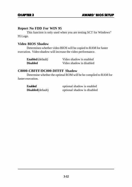
Report No FDD For WIN 95This function is only used when you are testing SCT for Windows®
95 Logo.
Video BIOS ShadowDetermines whether video BIOS will be copied to RAM for faster
execution. Video shadow will increase the video performance.
Enabled (default) Video shadow is enabledDisabled Video shadow is disabled
C8000-CBFFF/DC000-DFFFF ShadowDetermine whether the optimal ROM will be be compiled to RAM for
faster execution.
Enabled optional shadow is enabledDisabled(default) optional shadow is disabled

CHAPTER 3CHAPTER 3CHAPTER 3CHAPTER 3CHAPTER 3 AWARDAWARDAWARDAWARDAWARD® BIOS SETUP BIOS SETUP BIOS SETUP BIOS SETUP BIOS SETUP
3-13
SDRAM Controlled by :Manual
SDRAM RAS to CAS Delay :3
SDRAM RAS Precharge Time :3
SDRAM CAS Latency Time :3
DRAM Data Integrity Mode :Non-ECC
System BIOS Cacheable :Disabled
Video BIOS Cacheable : Disabled
Video RAM Cacheable :Disabled
8 Bit I/O Recovery Time :1
16 Bit I/O Recovery Time :1
Memory Hole at 15M-16M : Disabled
Passive Release :Enabled
Delayed Transaction :Disabled
AGP Aperture Size (MB) :64
3.6 3.6 3.6 3.6 3.6 Chipset Features SetupChipset Features SetupChipset Features SetupChipset Features SetupChipset Features Setup
The Chipset Features Setup option is used to change the values ofthe chipset registers. These registers control most of the system options inthe computer.
Choose the “CHIPSET FEATURES SETUP” from the Main Menu andthe following screen will appear.
ROM PCI/ISA BIOS(2A59IM4A)CMOS SETUP UTILITY
CHIPSET FEATURES SETUP
Note: Change these settings only if you are familiar with the chipset.
Esc : Quit ↑ ↓ → ← : Select item
F1 : Help PU/PD/+/- : modify
F5 : Old Value(Shift) F2 : Color
F6 : Load BIOS Defaults
F7 : Load Setup Defaults
Auto Detect DIMM/PCI Clk :Enabled
Spread Spectrum Modulated:Enabled
CHAPTER 3CHAPTER 3CHAPTER 3CHAPTER 3CHAPTER 3 AWARDAWARDAWARDAWARDAWARD® BIOS SETUP BIOS SETUP BIOS SETUP BIOS SETUP BIOS SETUP
3-14
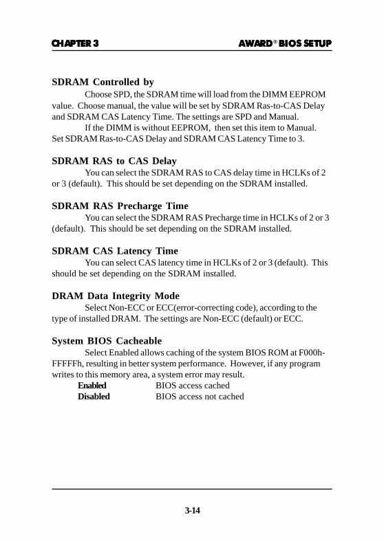
SDRAM Controlled byChoose SPD, the SDRAM time will load from the DIMM EEPROM
value. Choose manual, the value will be set by SDRAM Ras-to-CAS Delayand SDRAM CAS Latency Time. The settings are SPD and Manual.
If the DIMM is without EEPROM, then set this item to Manual.Set SDRAM Ras-to-CAS Delay and SDRAM CAS Latency Time to 3.
SDRAM RAS to CAS DelayYou can select the SDRAM RAS to CAS delay time in HCLKs of 2
or 3 (default). This should be set depending on the SDRAM installed.
SDRAM RAS Precharge TimeYou can select the SDRAM RAS Precharge time in HCLKs of 2 or 3
(default). This should be set depending on the SDRAM installed.
SDRAM CAS Latency TimeYou can select CAS latency time in HCLKs of 2 or 3 (default). This
should be set depending on the SDRAM installed.
DRAM Data Integrity ModeSelect Non-ECC or ECC(error-correcting code), according to the
type of installed DRAM. The settings are Non-ECC (default) or ECC.
System BIOS CacheableSelect Enabled allows caching of the system BIOS ROM at F000h-
FFFFFh, resulting in better system performance. However, if any programwrites to this memory area, a system error may result.
Enabled BIOS access cachedDisabled BIOS access not cached

CHAPTER 3CHAPTER 3CHAPTER 3CHAPTER 3CHAPTER 3 AWARDAWARDAWARDAWARDAWARD® BIOS SETUP BIOS SETUP BIOS SETUP BIOS SETUP BIOS SETUP
3-15
Video BIOS CacheableSelect Enabled allows caching of the system BIOS ROM at C0000h-
F7FFFh, resulting in better video performance. However, if any programwrites to this memory area, a system error may result.
Enabled Video BIOS access cachedDisabled Video BIOS access not cached
Video RAM CacheableSelect Enabled allows caching of the video RAM, resulting in better
system performance. However, if any program writes to this memory area, asystem error may result.
8 Bit I/O Recovery TimeThe recovery time is the length of time, measured in CPU clocks,
which the system will delay after the completion of an input/output request.This delay takes place because the CPU is operating so much faster than theinput/output bus that the CPU must be delayed to allow for the completionof the I/O.
This item allows you to determine the recovery time allowed for 8 bitI/O. Choices are from NA, 1 to 8 CPU clocks.
16 Bit I/O Recovery TimeThis item allows you to determine the recovery time allowed for 16 bit
I/O. Choices are from NA, 1 to 4 CPU clocks.
Memory Hole At 15M-16MIn order to improve performance, certain space in memory can be
reserved for ISA cards. This memory must be mapped into the memoryspace below 16 MB.
Enabled Memory hole supported.Disabled Memory hole not supported.
Passive ReleaseWhen Enabled, CPU to PCI bus accesses are allowed during passive
release. Otherwise, the arbiter only accepts another PCI master access tolocal DRAM. The settings are Enabled or Disabled.

CHAPTER 3CHAPTER 3CHAPTER 3CHAPTER 3CHAPTER 3 AWARDAWARDAWARDAWARDAWARD® BIOS SETUP BIOS SETUP BIOS SETUP BIOS SETUP BIOS SETUP
3-16
Delayed TransactionThe chipset has an embedded 32-bit posted write buffer to support
delay transactions cycles. Select Enabled to support compliance with PCIspecification version 2.1. The settings are Enabled or Disabled.
AGP Aperture Size (MB)Select the size of the Accelerated Graphics Port (AGP) aperture.
The aperture is a portion of the PCI memory address range dedicated forgraphics memory address space. Host cycles that hit the aperture range areforwarded to the AGP without any translation.
Auto Detect DIMM/PCI ClkThis item allows you to select theDIMM/PCI clock. The other
sockets will not generate when DIMM/PCI cards are not installed. Thesetting should be set to enabled which works better for EMI.
Spread Spectrum ModulatedThis item allows you to select the clock generator Spread Spectrum
function. The default is enabled. This item should always be set toDisabled, if you over-clock the processor.

CHAPTER 3CHAPTER 3CHAPTER 3CHAPTER 3CHAPTER 3 AWARDAWARDAWARDAWARDAWARD® BIOS SETUP BIOS SETUP BIOS SETUP BIOS SETUP BIOS SETUP
3-17
3.7 Power Management Setup3.7 Power Management Setup3.7 Power Management Setup3.7 Power Management Setup3.7 Power Management Setup
The Power Management Setup will appear on your screen like this:
ROM PCI/ISA BIOS (2A59IM4A)POWER MANAGEMENT SETUP
AWARD SOFTWARE, INC.
Power ManagementThis category determines the power consumption for system after
selecting below items. Default value is user define. The following pages tellyou the options of each item & describe the meanings of each options.
Power Management :User DefinePM Control by APM :YesVideo Off Method :DPMSVideo Off After :StandbyModem Use IRQ :3Reserve IRQ9 :YesDoze Mode :DisableStandby Mode :DisableSuspend Mode :DisableHDD Power Down :DisableThrottle Duty Cycle :62.5%VGA Active Monitor :DisabledSoft-Off by PWR-BTTN :Instant-OffCPUFAN off in Suspend :EnabledResume by Ring :DisabledResume by Alarm :DisabledDate(of Month) Alarm :2Time(hh:mm:ss) Alarm : 0:0:0
Restore AC/Power Loss :Off
Esc : Quit ↑ ↓ → ← : Select item
F1 : Help PU/PD/+/- : modify
F5 : Old Value(Shift) F2 : Color
F6 : Load BIOS Defaults
F7 : Load Setup Defaults
Power status LED :Single ColorWake Up on LAN :DisabledIRQ 8 Break Suspend :Disabled
** Reload Global Timer Events **IRQ [3-7,9-15],NMI : DisabledPrimary IDE 0 : EnabledPrimary IDE 1 : EnabledSecondary IDE 0 : DisabledSecondary IDE 1 : DisabledFloppy Disk : DisabledSerial Port : EnabledParallel Port : Disabled

CHAPTER 3CHAPTER 3CHAPTER 3CHAPTER 3CHAPTER 3 AWARDAWARDAWARDAWARDAWARD® BIOS SETUP BIOS SETUP BIOS SETUP BIOS SETUP BIOS SETUP
3-18
Power ManagementDisable Global Power Management will be disabled.User Define Users can configure their own power manage-
ment.Min Saving Pre-defined timer values are used such that all
timers are in their MAX value.Max Saving Pre-defined timer values are used such that all
timers are in their MIN value.
PM Control by APMNo System BIOS will ignore APM when
power managing the system.Yes System BIOS will wait for APM’s
prompt before it enter any PM modeNote :Enable this for O.S. with APM like Windows® 95/98, Windows® NT,etc.
Video Off MethodBlank Screen The system BIOS will only blank off
the screen when disabling video.V/H SYN C+Blank In addition to (1), BIOS will also turn
off the V-SYNC & H-SYNC signalsfrom VGA card to monitor.
DPMS This function is enabled only for VGAcard supporting DPMS.
Note: Green monitors detect the V/H SYNC signals to turn off its electrongun.

CHAPTER 3CHAPTER 3CHAPTER 3CHAPTER 3CHAPTER 3 AWARDAWARDAWARDAWARDAWARD® BIOS SETUP BIOS SETUP BIOS SETUP BIOS SETUP BIOS SETUP
3-19
Video Off AfterThe settings are N/A, Standby, Doze, or Suspend. This option is for
choosing the setting in which the monitor will turn off.N/A Always turn on.Doze During Doze mode, the monitor will be turned off.Standby During Standby mode, the monitor will be turned off.Suspend During Suspend mode, the monitor will be turned off.The default setting is Standby.
MODEM Use IRQName the interrupt request (IRQ) line assigned to the modem (if any)
on your system. Activity of the selected IRQ always awakens the system.The settings are NA, 3, 4, 5, 7, 9, 10, or 11.
Reserve IRQ 9This item is reserved for Windows 98 ACPI mode. Choose yes, if
you use Windows 98 ACPI mode. Otherwise, set to no.
Doze ModeDisable System will never enter DOZE mode.
1 Min/2 Min/4 Min/8 Min/12 Min/20 Min/30 Min/40 Min/1 Hr
Defines the continuous idle time before thesystem enters DOZE mode.If any item defined in the options of “PowerDown and Resume events” is enabled & active,DOZE timer will be reloaded. When the systemhave entered Doze mode, any of the itemsenabled in “Wake Up Events in Doze andStandby” will trigger the system to wake up.

CHAPTER 3CHAPTER 3CHAPTER 3CHAPTER 3CHAPTER 3 AWARDAWARDAWARDAWARDAWARD® BIOS SETUP BIOS SETUP BIOS SETUP BIOS SETUP BIOS SETUP
3-20
HDD Power DownDisable HDD’s motor will not shut off.
1 Min/2 Min/3 Min/4 Min/5 Min/6 Min/7 Min/8 Min/ 9 Min/10 Min/11 Min/12 Min/13 Min/14 Min/15 Min
Standby Mode Disable System will never enter STANDBY mode.
1 Min/2 Min/4 Min/8 Min/12 Min/20 Min/30 Min/40 Min/1 Hr
Suspend ModeDisable System will never enter SUSPEND mode.
1 Min/2 Min/4 Min/8 Min/12 Min/20 Min/30 Min/40 Min/1 Hr
Defines the continuous idle time before thesystem enters SUSPEND mode.If any item defined in the options of “PowerDown & Resume Events” is enabled & active,SUSPEND timer will be reloaded. When thesystem has entered SUSPEND mode, any of theitems enabled in the “Power Down & ResumeEvents” will trigger the system to wake up.
Defines the continuous HDD idle time beforethe HDD enters the power saving mode (motoroff). BIOS will turn off the HDD’s motor whentime is out.
Defines the continuous idle time before thesystem enters STANDBY mode.If any item defined in the options of “PowerDown and Resume events” is enabled & active,STANDBY timer will be reloaded. When thesystem has entered Standby mode , any of theitems that are enabled in “Wake Up Events ofDoze and Standby” will trigger the system towake up.

CHAPTER 3CHAPTER 3CHAPTER 3CHAPTER 3CHAPTER 3 AWARDAWARDAWARDAWARDAWARD® BIOS SETUP BIOS SETUP BIOS SETUP BIOS SETUP BIOS SETUP
3-21
Throttle Duty CycleThis option will determine how much power will be used by the CPU ,
if the system goes into suspend mode.
VGA Active MonitorDuring Enabled, if there’s no activity in the monitor screen, the
system will go into Power Saving Mode. During Disabled, the system willgo into Power Saving Mode, whether there is activity in the monitor screenor not. The settings are Disabled and Enabled.
Soft-Off by PWR-BTTNThe settings are Delay 4 sec or Instant-off. During Delay 4 sec, if
you push the switch once, the system goes into suspend mode. If you pushit more than 4 seconds, the system will be turned off. During instant-off, thesystem will turn off once you push the switch.
CPUFAN Off in SuspendDuring Enabled, if the system goes into suspend mode, the CPU fan
will stop. During Disabled, if the system goes into suspend mode, the CPUfan will resume.
Resume by RingDuring Disabled, the system will ignore any incoming call from the
modem. During Enabled, the system will boot up if there’s an incoming callfrom the modem.Note: If you have change the setting, you must let the system boot up until
it goes to the operating system, before this function will work.
Resume by AlarmThis function is for setting date and time for your computer to boot
up. During Disabled, you cannot use this function. During Enabled, choosethe Date and Time Alarm:
Date(of month) Alarm You can choose which month thesystem will boot up. Set to 0, to bootevery month.
Time(hh:mm:ss) Alarm You can choose what hour, minute andsecond the system will boot up.
Note: If you have change the setting, you must let the system boot up untilit goes to the operating system, before this function will work.

CHAPTER 3CHAPTER 3CHAPTER 3CHAPTER 3CHAPTER 3 AWARDAWARDAWARDAWARDAWARD® BIOS SETUP BIOS SETUP BIOS SETUP BIOS SETUP BIOS SETUP
3-22
Restore AC/Power LossThe settings are power ON/OFF or Last Status. During power ON,
after every AC/Power Loss, the system will be turned on. During last status,after every AC/Power Loss, whatever the system status, it will be the samewhen the AC power returns. During Off, after every AC/Power Loss, thesystem will be shutdown.
Power LEDThis item determines which state the Power LED will use. The
settings are Blink, Dual color, and Single color. During blink, the power LEDwill blink when the system enters the suspend mode. When the mode is inDual Color, the power LED will change its color. Choose the single colorand the power LED will always remain lit.
Wake Up On LANTo use this function, you need a LAN add-on card which support
power on functions. It should also support the wake-up on LAN jumper(JWOL1).
Enabled Wake up on LAN supported.Disabled Wake up on LAN not supported.
Power Status LEDThis item determines which status the Power LED will use. The
settings are Blink, Dual Color, and Single Color. During Blink, the power LEDwill blink when the system enters the suspend mode. When the mode is inDual Color, the power LED will change its color during suspend mode.Choose the Single Color and the power LED will always remain lit.
CHAPTER 3CHAPTER 3CHAPTER 3CHAPTER 3CHAPTER 3 AWARDAWARDAWARDAWARDAWARD® BIOS SETUP BIOS SETUP BIOS SETUP BIOS SETUP BIOS SETUP
3-23
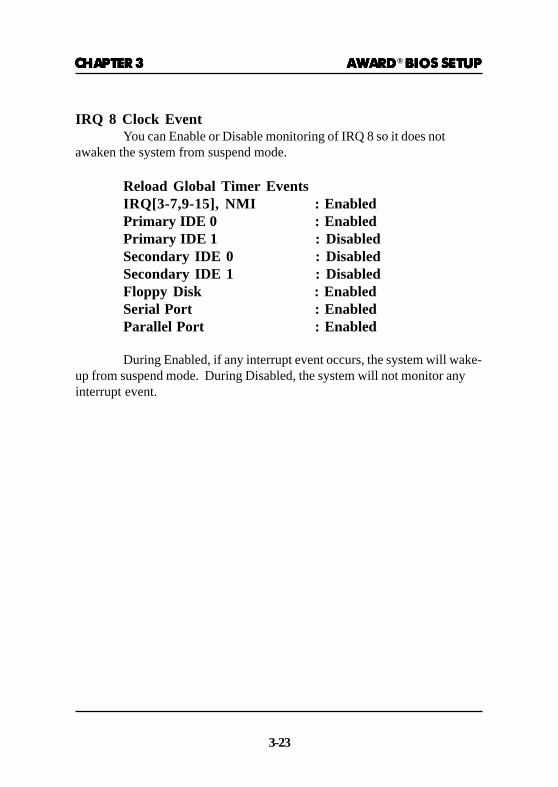
IRQ 8 Clock EventYou can Enable or Disable monitoring of IRQ 8 so it does not
awaken the system from suspend mode.
Reload Global Timer EventsIRQ[3-7,9-15], NMI : EnabledPrimary IDE 0 : EnabledPrimary IDE 1 : DisabledSecondary IDE 0 : DisabledSecondary IDE 1 : DisabledFloppy Disk : EnabledSerial Port : EnabledParallel Port : Enabled
During Enabled, if any interrupt event occurs, the system will wake-up from suspend mode. During Disabled, the system will not monitor anyinterrupt event.
CHAPTER 3CHAPTER 3CHAPTER 3CHAPTER 3CHAPTER 3 AWARDAWARDAWARDAWARDAWARD® BIOS SETUP BIOS SETUP BIOS SETUP BIOS SETUP BIOS SETUP
3-24
3.8 PNP/PCI Configuration Setup3.8 PNP/PCI Configuration Setup3.8 PNP/PCI Configuration Setup3.8 PNP/PCI Configuration Setup3.8 PNP/PCI Configuration Setup
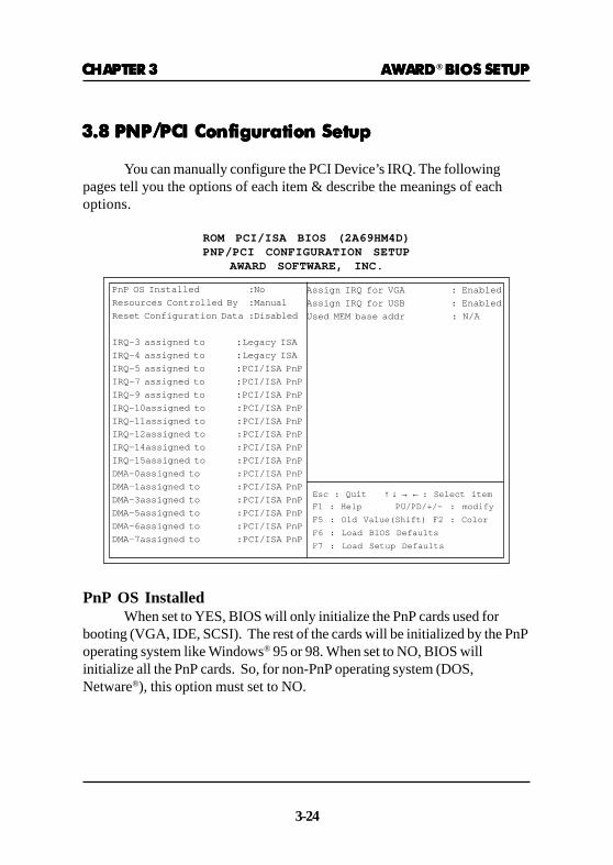
You can manually configure the PCI Device’s IRQ. The followingpages tell you the options of each item & describe the meanings of eachoptions.
ROM PCI/ISA BIOS (2A69HM4D)PNP/PCI CONFIGURATION SETUP
AWARD SOFTWARE, INC.
PnP OS InstalledWhen set to YES, BIOS will only initialize the PnP cards used for
booting (VGA, IDE, SCSI). The rest of the cards will be initialized by the PnPoperating system like Windows® 95 or 98. When set to NO, BIOS willinitialize all the PnP cards. So, for non-PnP operating system (DOS,Netware®), this option must set to NO.
PnP OS Installed :No
Resources Controlled By :Manual
Reset Configuration Data :Disabled
IRQ-3 assigned to :Legacy ISA
IRQ-4 assigned to :Legacy ISA
IRQ-5 assigned to :PCI/ISA PnP
IRQ-7 assigned to :PCI/ISA PnP
IRQ-9 assigned to :PCI/ISA PnP
IRQ-10assigned to :PCI/ISA PnP
IRQ-11assigned to :PCI/ISA PnP
IRQ-12assigned to :PCI/ISA PnP
IRQ-14assigned to :PCI/ISA PnP
IRQ-15assigned to :PCI/ISA PnP
DMA-0assigned to :PCI/ISA PnP
DMA-1assigned to :PCI/ISA PnP
DMA-3assigned to :PCI/ISA PnP
DMA-5assigned to :PCI/ISA PnP
DMA-6assigned to :PCI/ISA PnP
DMA-7assigned to :PCI/ISA PnP
Assign IRQ for VGA : Enabled
Assign IRQ for USB : Enabled
Used MEM base addr : N/A
Esc : Quit ↑ ↓ → ← : Select item
F1 : Help PU/PD/+/- : modify
F5 : Old Value(Shift) F2 : Color
F6 : Load BIOS Defaults
F7 : Load Setup Defaults
CHAPTER 3CHAPTER 3CHAPTER 3CHAPTER 3CHAPTER 3 AWARDAWARDAWARDAWARDAWARD® BIOS SETUP BIOS SETUP BIOS SETUP BIOS SETUP BIOS SETUP
3-25
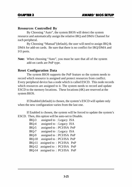
Resources Controlled ByBy Choosing “Auto”, the system BIOS will detect the system
resource and automatically assign the relative IRQ and DMA Channel foreach peripheral.
By Choosing “Manual”(default), the user will need to assign IRQ &DMA for add-on cards. Be sure that there is no conflict for IRQ/DMA andI/O ports.
Note: When choosing “Auto”, you must be sure that all of the systemadd-on cards are PnP type.
Reset Configuration DataThe system BIOS supports the PnP feature so the system needs to
record which resource is assigned and protect resources from conflict.Every peripheral device has a node which is called ESCD. This node recordswhich resources are assigned to it. The system needs to record and updateESCD to the memory locations. These locations (4K) are reserved at thesystem BIOS.
If Disabled (default) is chosen, the system’s ESCD will update onlywhen the new configuration varies from the last one.
If Enabled is chosen, the system will be forced to update the system’sESCD. Then, this option will be auto-set to Disable.
IRQ-3 assigned to : Legacy ISAIRQ-4 assigned to : Legacy ISAIRQ-5 assigned to : PCI/ISA PnPIRQ-7 assigned to : Legacy ISAIRQ-9 assigned to : PCI/ISA PnPIRQ-10 assigned to : PCI/ISA PnPIRQ-11 assigned to : PCI/ISA PnPIRQ-12 assigned to : PCI/ISA PnPIRQ-14 assigned to : PCI/ISA PnP
CHAPTER 3CHAPTER 3CHAPTER 3CHAPTER 3CHAPTER 3 AWARDAWARDAWARDAWARDAWARD® BIOS SETUP BIOS SETUP BIOS SETUP BIOS SETUP BIOS SETUP
3-26
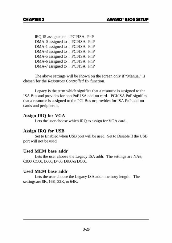
IRQ-15 assigned to : PCI/ISA PnPDMA-0 assigned to : PCI/ISA PnPDMA-1 assigned to : PCI/ISA PnPDMA-3 assigned to : PCI/ISA PnPDMA-5 assigned to : PCI/ISA PnPDMA-6 assigned to : PCI/ISA PnPDMA-7 assigned to : PCI/ISA PnP
The above settings will be shown on the screen only if “Manual” ischosen for the Resources Controlled By function.
Legacy is the term which signifies that a resource is assigned to theISA Bus and provides for non PnP ISA add-on card. PCI/ISA PnP signifiesthat a resource is assigned to the PCI Bus or provides for ISA PnP add-oncards and peripherals.
Assign IRQ for VGALets the user choose which IRQ to assign for VGA card.
Assign IRQ for USBSet to Enabled when USB port will be used. Set to Disable if the USB
port will not be used.
Used MEM base addrLets the user choose the Legacy ISA addr. The settings are NA#,
C800, CC00, D000, D400, D800 or DC00.
Used MEM base addrLets the user choose the Legacy ISA addr. memory length. The
settings are 8K, 16K, 32K, or 64K.

CHAPTER 3CHAPTER 3CHAPTER 3CHAPTER 3CHAPTER 3 AWARDAWARDAWARDAWARDAWARD® BIOS SETUP BIOS SETUP BIOS SETUP BIOS SETUP BIOS SETUP
3-27
3.9 Load BIOS/Setup Defaults3.9 Load BIOS/Setup Defaults3.9 Load BIOS/Setup Defaults3.9 Load BIOS/Setup Defaults3.9 Load BIOS/Setup Defaults
This Main Menu item loads the default system values. If the CMOSis corrupted, the defaults are loaded automatically. Choose this item and thefollowing message appears:
“ Load Setup Defaults (Y / N) ? N “
To use the Setup defaults, change the prompt to “Y” and press < Enter >
Note: The Setup defaults can be customized to increase performance.However the BIOS defaults can always be used as a back up ifthere is some problem with the mainboard operation.
CHAPTER 3CHAPTER 3CHAPTER 3CHAPTER 3CHAPTER 3 AWARDAWARDAWARDAWARDAWARD® BIOS SETUP BIOS SETUP BIOS SETUP BIOS SETUP BIOS SETUP
3-28
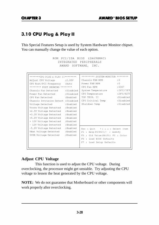
3.10 CPU Plug & Play II
This Special Features Setup is used by System Hardware Monitor chipset.You can manually change the value of each option.
ROM PCI/ISA BIOS (2A69HM4C)INTEGRATED PERIPHERALS
AWARD SOFTWARE, INC.
*******CPU PLUG & PLAY II********
Adjust CPU Voltage :2.00V
CPU Host/PCI Frequency :Auto
******** POST SHOWING ********
Chassis Fan Detected : Disabled
Power Fan Detected : Disabled
CPU Fan Detected :Enabled
Chassis Intrusion Detect : Disabled
Voltage Detected : Enabled
Vcore Voltage Detected : Enabled
+2.5V Voltage Detected : Enabled
+3.3V Voltage Detected : Enabled
+5.0V Voltage Detected : Enabled
+ 12V Voltage Detected :Enabled
- 12V Voltage Detected : Enabled
-5.0V Voltage Detected : Enabled
VBat Voltage Detected :Enabled
5VSB Voltage Detected :Enabled
Esc : Quit ↑ ↓ → ← : Select item
F1 : Help PU/PD/+/- : modify
F5 : Old Value(Shift) F2 : Color
F6 : Load BIOS Defaults
F7 : Load Setup Defaults
********* SYSTEM MONITOR ********
Chassis FAN RPM :0
Power FAN RPM :0
CPU Fan RPM : 6367
System Temperature :26 0C/78 0F
CPU Temperature :28 0C/82 0F
TOP TECH. II :Disabled
CPU Critical Temp : Disabled
Shutdown Temp : Disabled
Adjust CPU VoltageThis function is used to adjust the CPU voltage. During
overclocking, the processor might get unstable. Try adjusting the CPUvoltage to lessen the heat generated by the CPU voltage.
NOTE: We do not guarantee that Motherboard or other components willwork properly after overclocking.

CHAPTER 3CHAPTER 3CHAPTER 3CHAPTER 3CHAPTER 3 AWARDAWARDAWARDAWARDAWARD® BIOS SETUP BIOS SETUP BIOS SETUP BIOS SETUP BIOS SETUP
3-29
CPU Host/PCI FrequencyCheck your processor and set this function accordingly. You can set
the CPU Frequency accordingly. CPU Frequenies are: 66, 68, 75, 83 and 100,103, 112, 117, 124, 129, 133, 138, 143, 148, 153. Though 68, 75, 83, 103, 112,117, 124, 129, 133, 138, 143, 148 and 153 frequencies are available, it isadvised that you use these only for testing since this is not stable as theCPU is not designed for these frequencies.
Note: If the CPU Bus Frequency is set too high, the system may not bootup,then restart the system. Press “F10” until bootup. This will set the defaultsetting.
Chassis Fan Detected/Power Fan Detected/CPU Fan +1.5VDetected/Voltage Detected/Vcore Voltage Detected/+2.5VVoltage Detected/+3.3V Voltage Detected/+5.0 VoltageDetected/+12V Voltage Detected/-12V Voltage Detected/-5.0Voltage Detected/VBat Voltage Detected/5VSB VoltageDetected
During Enabled, this will show the CPU/FAN voltage chart duringsystem boot up. During Disabled, this will not show.
Chassis Intrusion DetectSet this option to Enabled, Reset, or Disabled the chassis intrusion
detector. During Enabled, any intrusion on the system chassis will berecorded. The next time you turn on the system, it will show a warningmessage. To be able to clear those warning, choose Reset. After clearingthe message it will go back to Enabled.

CHAPTER 3CHAPTER 3CHAPTER 3CHAPTER 3CHAPTER 3 AWARDAWARDAWARDAWARDAWARD® BIOS SETUP BIOS SETUP BIOS SETUP BIOS SETUP BIOS SETUP
3-30
Chassis/Power/CPU Fan RPMDuring Enabled, this will monitor the RPM of your CPU/Chassis/
Power fan.
System Temperature/CPU TemperatureThis will show the System and CPU temperature.
TOP TECH. IIThis option is used to disabled or enabled the J12 connector 20 cm
thermistor. The default setting is Disabled (See page 2-30). When chooseEnabled, “TOP TECH II Temp” item will appear onscreen.
CPU Critical TempThis option is for setting the critical temperature level for the
processor. When the processor reach the temperature you set, this willreduce the load on the processor.
Shutdown TempThis option is for setting the Shutdown temperature level for the
processor. When the processor reach the temperature you set, this willshutdown the system. This function only works with Windows® 95/98operating system.

CHAPTER 3CHAPTER 3CHAPTER 3CHAPTER 3CHAPTER 3 AWARDAWARDAWARDAWARDAWARD® BIOS SETUP BIOS SETUP BIOS SETUP BIOS SETUP BIOS SETUP
3-31
3.11 Integrated Peripherals
ROM PCI/ISA BIOS (2A69HM4D)INTEGRATED PERIPHERALS
AWARD SOFTWARE, INC.
IDE HDD Block ModeEnabled/Disabled Enabled allows the Block mode access for the
IDE HDD.
IDE Primary Master PIOAuto/Mode0/Mode1-4
IDE Primary Slave PIOAuto/Mode0/Mode1-4
IDE Secondary Master PIOAuto/Mode0/Mode1-4
IDE HDD Block Mode : Enabled
IDE Primary Master PIO : Auto
IDE Primary Slave PIO : Auto
IDE Secondary Master PIO : Auto
IDE Secondary Slave PIO : Auto
IDE Primary Master UDMA : Auto
IDE Primary Slave UDMA : Auto
IDE Secondary Master UDMA: Auto
IDE Secondary Slave UDMA : Auto
On-Chip Primary PCI IDE : Enabled
On-Chip Primary PCI IDE : Enabled
USB Keyboard support :Disabled
Init Dislay First :PCI slot
Onboard Sound :Enable
Power On Function : Button
Onboard FDC controller : Enabled
Onboard Serial Port 1 : 3F8/IRQ4
Onboard Serial Port 2 : 2F8/IRQ3
Esc : Quit ↑ ↓ → ← : Select item
F1 : Help PU/PD/+/- : modify
F5 : Old Value(Shift) F2 : Color
F6 : Load BIOS Defaults
F7 : Load Setup Defaults
UART Mode Select : Normal
Onboard Parallel Mode : 378/IRQ7
Parallel Port Mode :SPP

CHAPTER 3CHAPTER 3CHAPTER 3CHAPTER 3CHAPTER 3 AWARDAWARDAWARDAWARDAWARD® BIOS SETUP BIOS SETUP BIOS SETUP BIOS SETUP BIOS SETUP
3-32
IDE Secondary Slave PIOAuto/Mode0/Mode1-4
For these 4 IDE options, choose “Auto” to have the system BIOSauto detect the IDE HDD operation mode for PIO access.
Note: Some IDE HDD cannot operate at the responding HDD’s mode.When the user has selected “Auto” and the system BIOS hasaccepted the HDD response mode, the user may degrade theHDD’s operation mode. Ex: IF the HDD reported that it can operate inmode 4 but it is not operating properly, the user will have tomanually change the operation mode to mode 3.
Choosing Mode 1-4 will have the system ignore the HDD’s reportedoperation mode and use the selected mode instead.
Note:According to ATA specs. Mode 4 transfer rate is > Mode 3 > Mode 2> Mode 1 > Mode 0. If the user’s HDD can operate at Mode 3 the usercan also select a slower Mode (i.e. Mode 0-2) but not a faster Mode (ieMode 4).
On-Chip Primary PCI IDEEnabled/Disabled
On-Chip Secondary PCI IDEEnabled/Disabled The system provides for an On-Board
On-Chipset PCI IDE controller thatsupports Dual Channel IDE (Primaryand Secondary). A maximum of 4 IDEdevices can be supported. If the userinstall the Off-Board PCI IDE controller(i.e. add-on cards), the user mustchoose which channels will be disabled.This will depend on which channel willbe used for the Off-Board PCI IDE add-on card.
CHAPTER 3CHAPTER 3CHAPTER 3CHAPTER 3CHAPTER 3 AWARDAWARDAWARDAWARDAWARD® BIOS SETUP BIOS SETUP BIOS SETUP BIOS SETUP BIOS SETUP
3-33
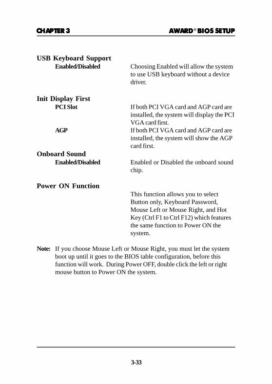
USB Keyboard SupportEnabled/Disabled Choosing Enabled will allow the system
to use USB keyboard without a devicedriver.
Init Display FirstPCI Slot If both PCI VGA card and AGP card are
installed, the system will display the PCIVGA card first.
AGP If both PCI VGA card and AGP card areinstalled, the system will show the AGPcard first.
Onboard SoundEnabled/Disabled Enabled or Disabled the onboard sound
chip.
Power ON FunctionThis function allows you to selectButton only, Keyboard Password,Mouse Left or Mouse Right, and HotKey (Ctrl F1 to Ctrl F12) which featuresthe same function to Power ON thesystem.
Note: If you choose Mouse Left or Mouse Right, you must let the systemboot up until it goes to the BIOS table configuration, before thisfunction will work. During Power OFF, double click the left or rightmouse button to Power ON the system.
CHAPTER 3CHAPTER 3CHAPTER 3CHAPTER 3CHAPTER 3 AWARDAWARDAWARDAWARDAWARD® BIOS SETUP BIOS SETUP BIOS SETUP BIOS SETUP BIOS SETUP
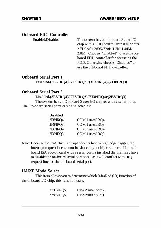
3-34
Onboard FDC ControllerEnabled/Disabled The system has an on-board Super I/O
chip with a FDD controller that supports2 FDDs for 360K/720K/1.2M/1.44M/2.8M. Choose “Enabled” to use the on-board FDD controller for accessing theFDD. Otherwise choose “Disabled” touse the off-board FDD controller.
Onboard Serial Port 1Disabled/(3F8/IRQ4)/(2F8/IRQ3)/ (3E8/IRQ4)/(2E8/IRQ3)
Onboard Serial Port 2Disabled/(3F8/IRQ4)/(2F8/IRQ3)/(3E8/IRQ4)/(2E8/IRQ3)The system has an On-board Super I/O chipset with 2 serial ports.
The On-board serial ports can be selected as:
Disabled3F8/IRQ4 COM 1 uses IRQ42F8/IRQ3 COM 2 uses IRQ33E8/IRQ4 COM 3 uses IRQ42E8/IRQ3 COM 4 uses IRQ3
Note: Because the ISA Bus Interrupt accepts low to high edge trigger, theinterrupt request line cannot be shared by multiple sources. If an off-board ISA add-on card with a serial port is installed the user may haveto disable the on-board serial port because it will conflict with IRQrequest line for the off-board serial port.
UART Mode SelectThis item allows you to determine which InfraRed (IR) function of
the onboard I/O chip, this function uses.
278H/IRQ5 Line Printer port 2378H/IRQ5 Line Printer port 1

CHAPTER 3CHAPTER 3CHAPTER 3CHAPTER 3CHAPTER 3 AWARDAWARDAWARDAWARDAWARD® BIOS SETUP BIOS SETUP BIOS SETUP BIOS SETUP BIOS SETUP
3-35
Onboard Parallel PortDisabled There is a built-in parallel port on the
on-board Super I/O chipset that pro-vides Standard, ECP, and EPP features.It has the following options:
Disable3BCH/IRQ7 Line Printer port 0278H/IRQ5 Line Printer port 2378H/IRQ5 Line Printer port 1
Onboard Parallel ModeSPP : Standard Parallel PortEPP : Enhanced Parallel PortECP : Extended Capability Port
To operate the onboard parallel port asStandard Parallel Port only, choose“SPP.” To operate the onboard parallelport in the ECP and SPP modes simulta-neously, choose “ECP/SPP.” Bychoosing “ECP”, the onboard parallelport will operate in ECP mode only.Choosing “ECP/EPP” will allow theonboard parallel port to support boththe ECP and EPP modes simultaneously.The ECP mode has to use the DMAchannel, so choose the onboard parallelport with the ECP feature. After select-ing it, the following message will appear:“ECP Mode Use DMA” At this time,the user can choose between DMAchannels 3 or 1. The onboard parallelport is EPP Spec. compliant, so after theuser chooses the onboard parallel portwith the EPP function, the following
(3BCH/IRQ7)/(278H/IRQ5)/(378H/IRQ5)
SPP/(EPP/SPP)/ECP(ECP/EPP)

CHAPTER 3CHAPTER 3CHAPTER 3CHAPTER 3CHAPTER 3 AWARDAWARDAWARDAWARDAWARD® BIOS SETUP BIOS SETUP BIOS SETUP BIOS SETUP BIOS SETUP
3-36
message will be displayed on thescreen: “EPP Mode Select.” At thistime either EPP 1.7 spec. or EPP 1.9 spec.can be chosen.

CHAPTER 3CHAPTER 3CHAPTER 3CHAPTER 3CHAPTER 3 AWARDAWARDAWARDAWARDAWARD® BIOS SETUP BIOS SETUP BIOS SETUP BIOS SETUP BIOS SETUP
3-37
3.12 Supervisor/User Password Setting3.12 Supervisor/User Password Setting3.12 Supervisor/User Password Setting3.12 Supervisor/User Password Setting3.12 Supervisor/User Password Setting
This Main Menu item lets you configure the system so that a pass-word is required each time the system boots or an attempt is made to enterthe Setup program. Supervisor Password allows you to change all CMOSsettings but the User Password setting doesn’t have this function. The wayto set up the passwords for both Supervisor and User are as follow:
1. Choose “Change Password” in the Main Menu and press <Enter>.The following message appears:
“Enter Password:”
2. The first time you run this option, enter your password up to 8 charactersonly and press <Enter>. The screen will not display the entered charac-ters. For no password, just press <Enter>.
3. After you enter the password, the following message appears promptingyou to confirm the password:
“Confirm Password:”
4. Enter exactly the same password you just typed in to confirm the pass-word and press <Enter>.
5. Move the cursor to Save & Exit Setup to save the password.
6. If you need to delete the password you entered before, choose theSupervisor Password and press <Enter>. It will delete the password thatyou had before.
7. Move the cursor to Save & Exit Setup to save the option you did. Other-wise, the old password will still be there when you turn on your machinenext time.
CHAPTER 3CHAPTER 3CHAPTER 3CHAPTER 3CHAPTER 3 AWARDAWARDAWARDAWARDAWARD® BIOS SETUP BIOS SETUP BIOS SETUP BIOS SETUP BIOS SETUP
3-38
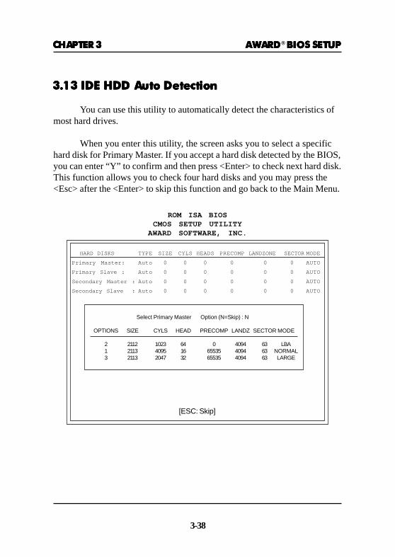
HARD DISKS TYPE SIZE CYLS HEADS PRECOMP LANDZONE SECTORMODE
Primary Master: Auto 0 0 0 0 0 0 AUTO
Primary Slave : Auto 0 0 0 0 0 0 AUTO
Secondary Master : Auto 0 0 0 0 0 0 AUTO
Secondary Slave : Auto 0 0 0 0 0 0 AUTO
Select Primary Master Option (N=Skip) : N
OPTIONS SIZE CYLS HEAD PRECOMP LANDZ SECTOR MODE
2 2112 1023 64 0 4094 63 LBA1 2113 4095 16 65535 4094 63 NORMAL3 2113 2047 32 65535 4094 63 LARGE
[ESC: Skip]
3.13 IDE HDD Auto Detection3.13 IDE HDD Auto Detection3.13 IDE HDD Auto Detection3.13 IDE HDD Auto Detection3.13 IDE HDD Auto Detection
You can use this utility to automatically detect the characteristics ofmost hard drives.
When you enter this utility, the screen asks you to select a specifichard disk for Primary Master. If you accept a hard disk detected by the BIOS,you can enter “Y” to confirm and then press <Enter> to check next hard disk.This function allows you to check four hard disks and you may press the<Esc> after the <Enter> to skip this function and go back to the Main Menu.
ROM ISA BIOSCMOS SETUP UTILITY
AWARD SOFTWARE, INC.