Chapter 28A - - Direct Current Circuits
39
Chapter 28A Chapter 28A - - Direct Current Circuits Direct Current Circuits A PowerPoint Presentation by Paul E. Tippens, Professor of Physics Southern Polytechnic State University A PowerPoint Presentation by A PowerPoint Presentation by Paul E. Tippens, Professor of Physics Paul E. Tippens, Professor of Physics Southern Polytechnic State University Southern Polytechnic State University © 2007
Transcript of Chapter 28A - - Direct Current Circuits
Chapter 28A Chapter 28A -- Direct Current CircuitsDirect Current Circuits
A PowerPoint Presentation by
Paul E. Tippens, Professor of Physics
Southern Polytechnic State University
A PowerPoint Presentation byA PowerPoint Presentation by
Paul E. Tippens, Professor of PhysicsPaul E. Tippens, Professor of Physics
Southern Polytechnic State UniversitySouthern Polytechnic State University
© 2007
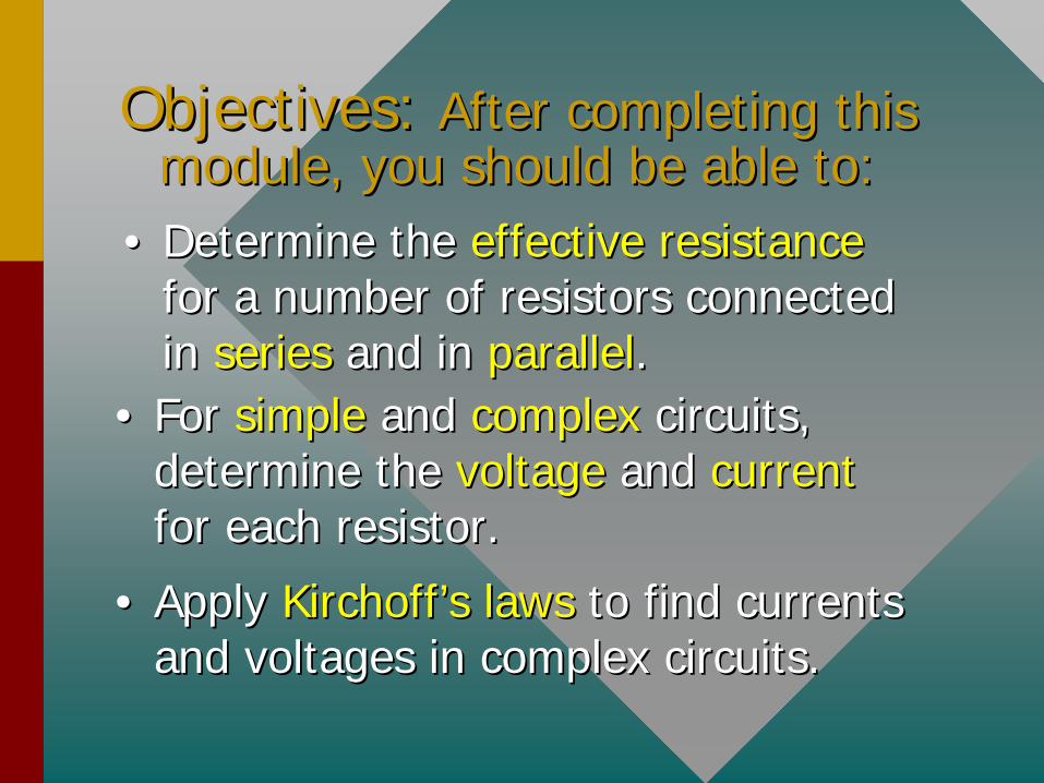
Objectives: Objectives: After completing this After completing this module, you should be able to:module, you should be able to:
•• Determine the Determine the effective resistanceeffective resistance for a number of resistors connected for a number of resistors connected in in seriesseries and in and in parallelparallel..
•• For For simplesimple and and complexcomplex circuits, circuits, determine the determine the voltage voltage andand currentcurrent for each resistor.for each resistor.
•• Apply Apply KirchoffKirchoff’’ss lawslaws to find currents to find currents and voltages in complex circuits.and voltages in complex circuits.
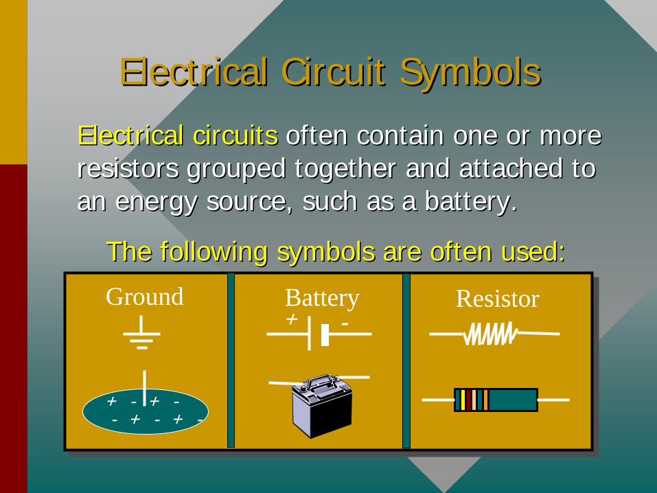
Electrical Circuit SymbolsElectrical Circuit Symbols
Electrical circuitsElectrical circuits often contain one or more often contain one or more resistors grouped together and attached to resistors grouped together and attached to an energy source, such as a battery.an energy source, such as a battery.
The following symbols are often used:The following symbols are often used:
+ - + -- + - + -
Ground Battery-+
Resistor
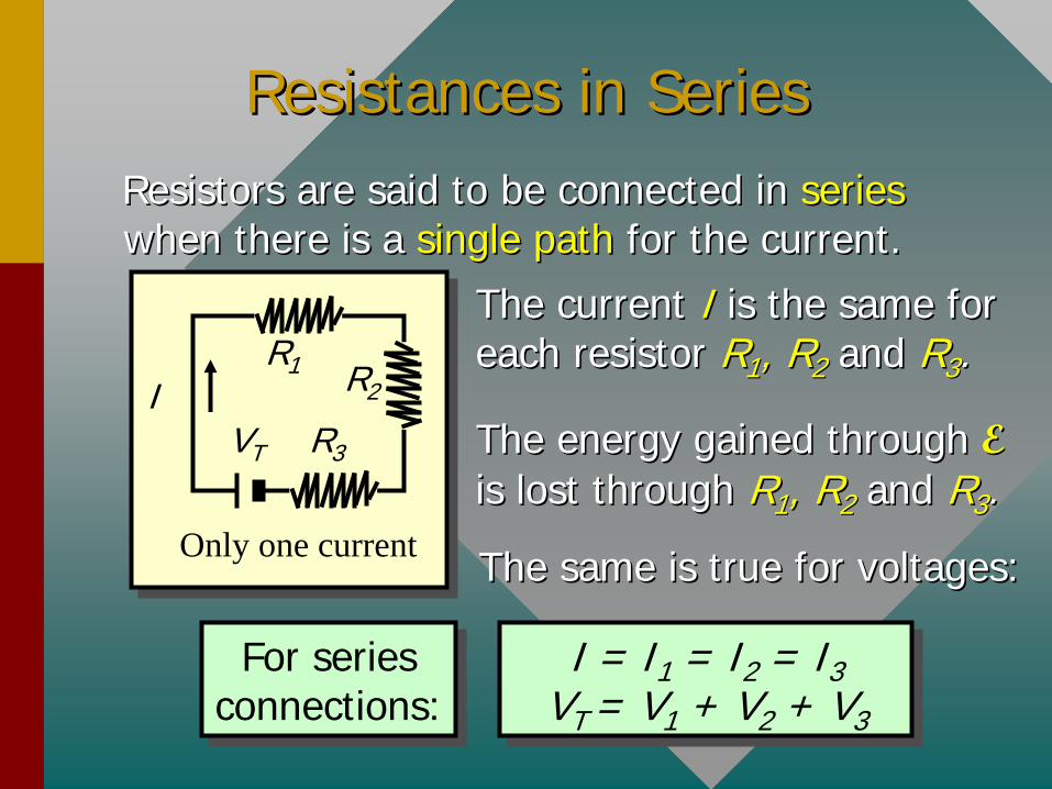
Resistances in SeriesResistances in SeriesResistors are said to be connected inResistors are said to be connected in series series when there is a when there is a single pathsingle path for the current.for the current.
The current The current I I is the same for is the same for each resistor each resistor RR11 , R, R22 and and RR33 ..
The energy gained through The energy gained through EE is lost through is lost through RR11 , R, R22 and and RR33 ..
The same is true for voltages:The same is true for voltages:
For series connections: For series
connections:I = I1 = I2 = I3
VT = V1 + V2 + V3
I = I1 = I2 = I3 VT = V1 + V2 + V3
R1I
VT
R2
R3
Only one current

Equivalent Resistance: SeriesEquivalent Resistance: SeriesThe The equivalent resistance Requivalent resistance Ree of a number of of a number of resistors connected in series is equal to the resistors connected in series is equal to the sumsum of the individual resistances.of the individual resistances.
VVT T = V= V11 + V+ V22 + V+ V33 ; (V = IR); (V = IR)
IITT RRee = I= I11 RR11 + I+ I22 RR22 + I+ I33 RR33
But . . . IBut . . . ITT = I= I11 = I= I22 = I= I33
Re = R1 + R2 + R3Re = R1 + R2 + R3
R1I
VT
R2
R3
Equivalent Resistance
Example 1:Example 1: Find the equivalent resistance RFind the equivalent resistance Ree . . What is the current I in the circuit?What is the current I in the circuit?
2
12 V1 3
Re = R1 + R2 + R3
Re = 3
+ 2
+ 1 = 6
Equivalent Re = 6 Equivalent Re = 6
The current is found from OhmThe current is found from Ohm’’s law: s law: V = V = IRIRee
12 V6 e
VIR
I = 2 AI = 2 A
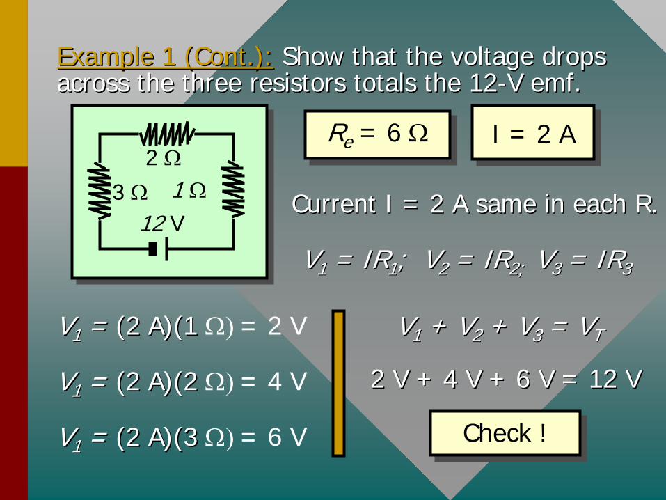
Example 1 (Cont.):Example 1 (Cont.): Show that the voltage drops Show that the voltage drops across the three resistors totals the 12across the three resistors totals the 12--V emf.V emf.
2
12 V1 3
Re = 6 Re = 6 I = 2 AI = 2 A
VV11 = IR= IR11 ; V; V22 = IR= IR2; 2; VV33 = IR= IR33
Current I = 2 A same in each R.Current I = 2 A same in each R.
VV11 = = (2 A)(1 (2 A)(1 = 2 V
VV11 = = (2 A)(2 (2 A)(2 = 4 V
VV11 = = (2 A)(3 (2 A)(3 = 6 V
VV11 + V+ V22 + V+ V33 = V= VTT
2 V + 4 V + 6 V = 12 V2 V + 4 V + 6 V = 12 V
Check !Check !
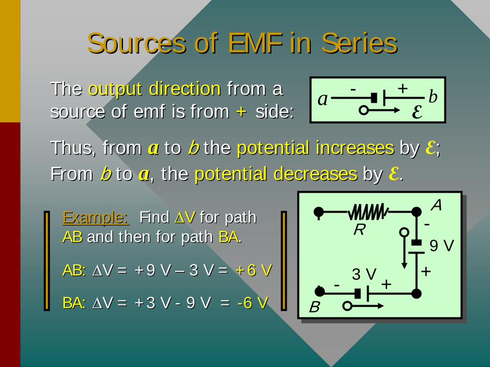
Sources of EMF in SeriesSources of EMF in SeriesThe The output directionoutput direction from a from a source of emf is from source of emf is from ++ side:side: E
+-a b
Thus, from Thus, from aa to to b b the the potential increasespotential increases by by E; ; From From bb to to aa, the , the potential decreasespotential decreases by by E..
Example:Example: Find Find V V for path for path AB AB and then for path and then for path BABA.. R
3 V +-
+
-9 V
A
B
AB: AB: V = +9 V V = +9 V –– 3 V = 3 V = +6 V+6 V
BA: BA: V = +3 V V = +3 V -- 9 V = 9 V = --6 V6 V
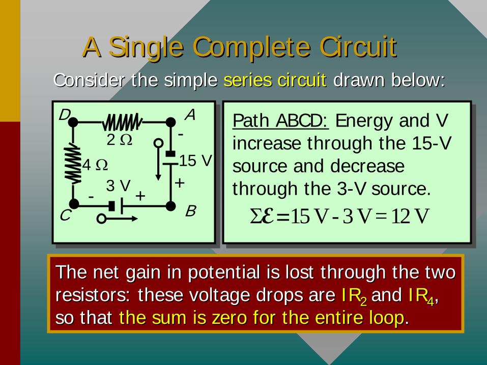
A Single Complete CircuitA Single Complete CircuitConsider the simple Consider the simple series circuitseries circuit drawn below:drawn below:
2
3 V +-
+
-15 V
A
C B
D
4
Path ABCD: Energy and V increase through the 15-V source and decrease through the 3-V source.
15 V - 3 V = 12 VE=
The net gain in potential is lost through the two The net gain in potential is lost through the two resistors: these voltage drops are resistors: these voltage drops are IRIR22 and and IRIR44 , , so that so that the sum is zero for the entire loopthe sum is zero for the entire loop..
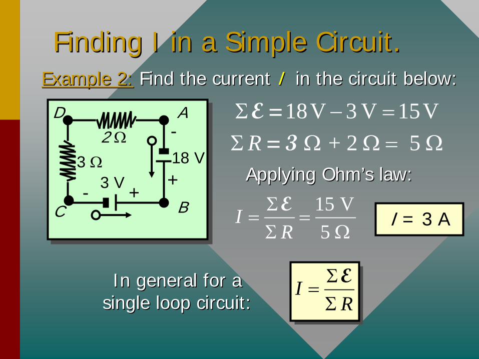
Finding I in a Simple Circuit.Finding I in a Simple Circuit.
2
3 V +-
+
-18 V
A
C B
D
3
Example 2:Example 2: Find the current Find the current I I in the circuit below:in the circuit below:
18V 3 V 15V E = + 2 5 R = 3
Applying OhmApplying Ohm’’s law:s law:
15 V5
IR
EI = 3 A
In general for a In general for a single loop circuit:single loop circuit:
IR
E

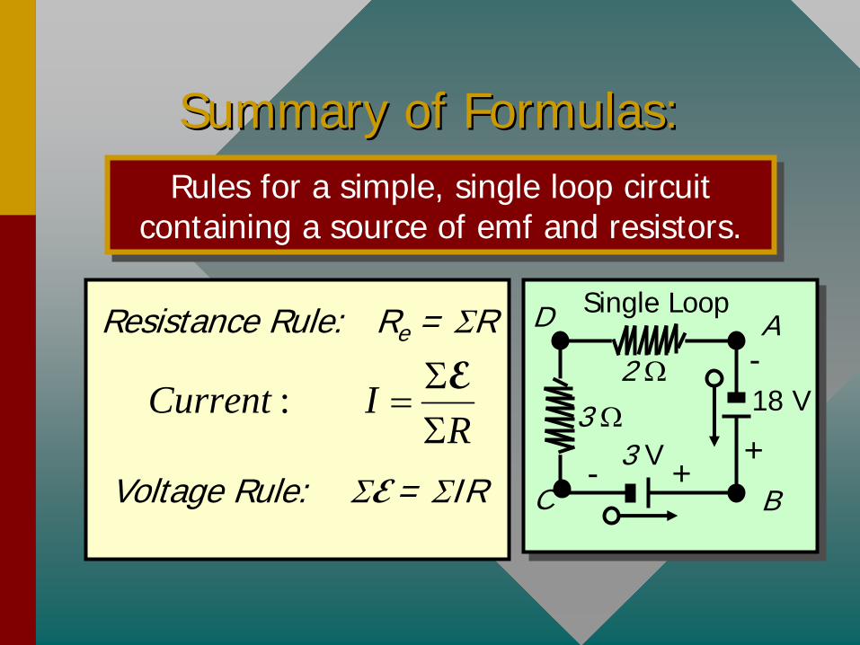
Summary: Single Loop Circuits:Summary: Single Loop Circuits:
Resistance Rule: Re = R
Voltage Rule: E = IR
: Current IR
E
R2
E1
E2R1
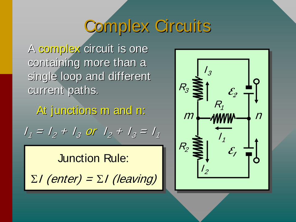
Complex CircuitsComplex CircuitsA A complexcomplex circuit is one circuit is one containing more than a containing more than a single loop and different single loop and different current paths.current paths.
R2 E1
R3 E2R1
I1
I3
I2
m nAt junctions m and n:At junctions m and n:
II11 = I= I22 + I+ I3 3 oror II22 + I+ I33 = I= I11
Junction Rule:
I (enter) = I (leaving)
Junction Rule:
I (enter) = I (leaving)
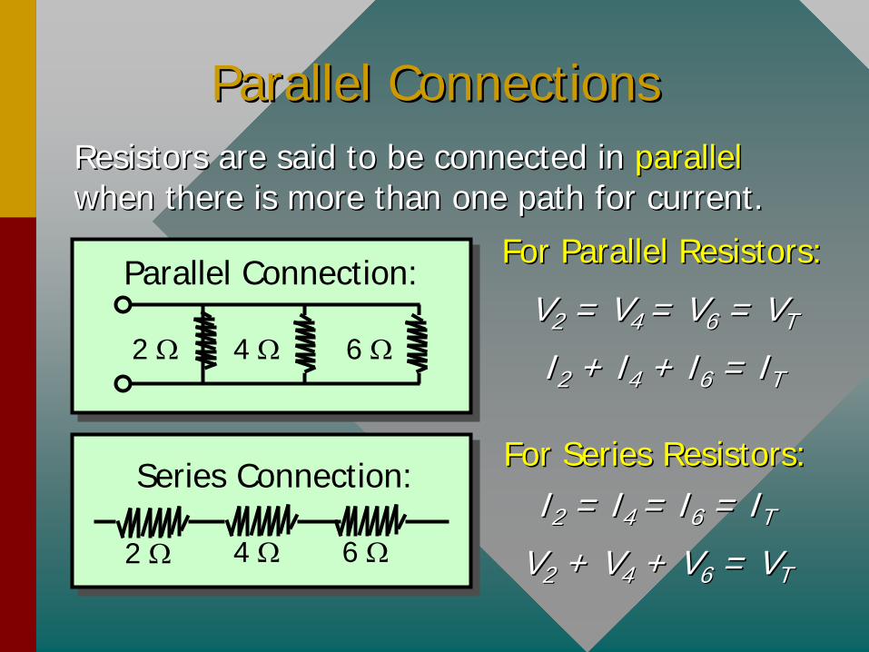
Parallel ConnectionsParallel ConnectionsResistors are said to be connected inResistors are said to be connected in parallel parallel when there is more than one path for current.when there is more than one path for current.
2 4 6
Series Connection: For Series Resistors:For Series Resistors:II22 = I= I4 4 = I= I66 = I= ITT
VV22 + V+ V44 + V+ V66 = V= VTT
Parallel Connection:
6 2 4
For Parallel Resistors:For Parallel Resistors:
VV22 = V= V4 4 = V= V66 = V= VTT
II22 + I+ I44 + I+ I66 = I= ITT
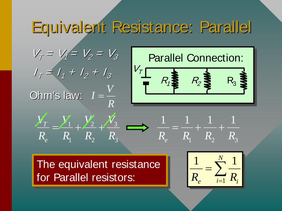
Equivalent Resistance: ParallelEquivalent Resistance: ParallelVVTT = V= V1 1 = V= V22 = V= V33
IITT = I= I11 + I+ I22 + I+ I33
OhmOhm’’s law:s law:VIR
31 2
1 2 3
T
e
VV V VR R R R
1 2 3
1 1 1 1
eR R R R
The equivalent resistance for Parallel resistors: The equivalent resistance for Parallel resistors: 1
1 1N
ie iR R
Parallel Connection:
R3R2
VTR1
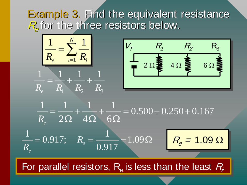
Example 3. Example 3. Find the equivalent resistance Find the equivalent resistance RR ee for the three resistors below.for the three resistors below.
R3R2VT R1
2 4 6 1
1 1N
ie iR R
1 2 3
1 1 1 1
eR R R R
1 1 1 1 0.500 0.250 0.1672 4 6eR
1 10.917; 1.090.917e
e
RR
Re = 1.09 Re = 1.09
For parallel resistors, Re is less than the least Ri .For parallel resistors, Re is less than the least Ri .

Example 3 (Cont.):Example 3 (Cont.): Assume a 12Assume a 12--V emf is V emf is connected to the circuit as shown. What is connected to the circuit as shown. What is the total current leaving the source of emf?the total current leaving the source of emf?
R3R2
12 V
R1
2 4 6
VT VVT T = = 12 V; 12 V; RRee = 1.09 = 1.09 VV1 1 = V= V22 = V= V33 = 12= 12 VV
IITT = I= I11 + I+ I22 + I+ I33
OhmOhm’’s Law:s Law: VIR
12 V
1.09 T
ee
VIR
Total current: IT = 11.0 A
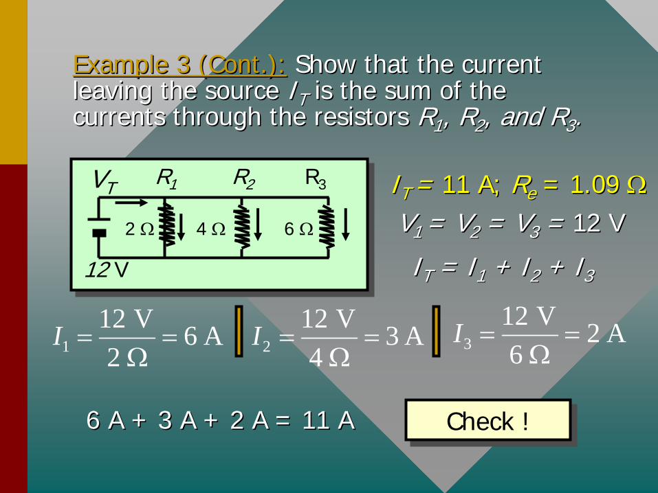
Example 3 (Cont.):Example 3 (Cont.): Show that the current Show that the current leaving the source leaving the source IITT is the sum of the is the sum of the currents through the resistors currents through the resistors RR11 , R, R22 , and R, and R33..
R3R2
12 V
R1
2 4 6
VT IIT T = = 11 A; 11 A; RRee = 1.09 = 1.09 VV1 1 = V= V22 = V= V33 = = 12 V12 V
IITT = I= I11 + I+ I22 + I+ I33
112 V 6 A2
I 2
12 V 3 A4
I
312 V 2 A6
I
6 A + 3 A + 2 A = 11 A6 A + 3 A + 2 A = 11 A Check !Check !
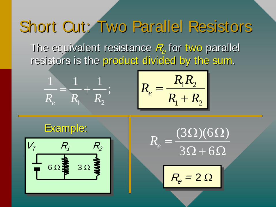
Short Cut: Two Parallel Resistors Short Cut: Two Parallel Resistors The equivalent resistance The equivalent resistance RRee for for twotwo parallel parallel resistors is the resistors is the product divided by the sumproduct divided by the sum..
1 2
1 1 1 ;eR R R 1 2
1 2e
R RRR R
(3 )(6 )3 6eR
Re = 2 Re = 2
Example:Example:
R2VT R1
6 3
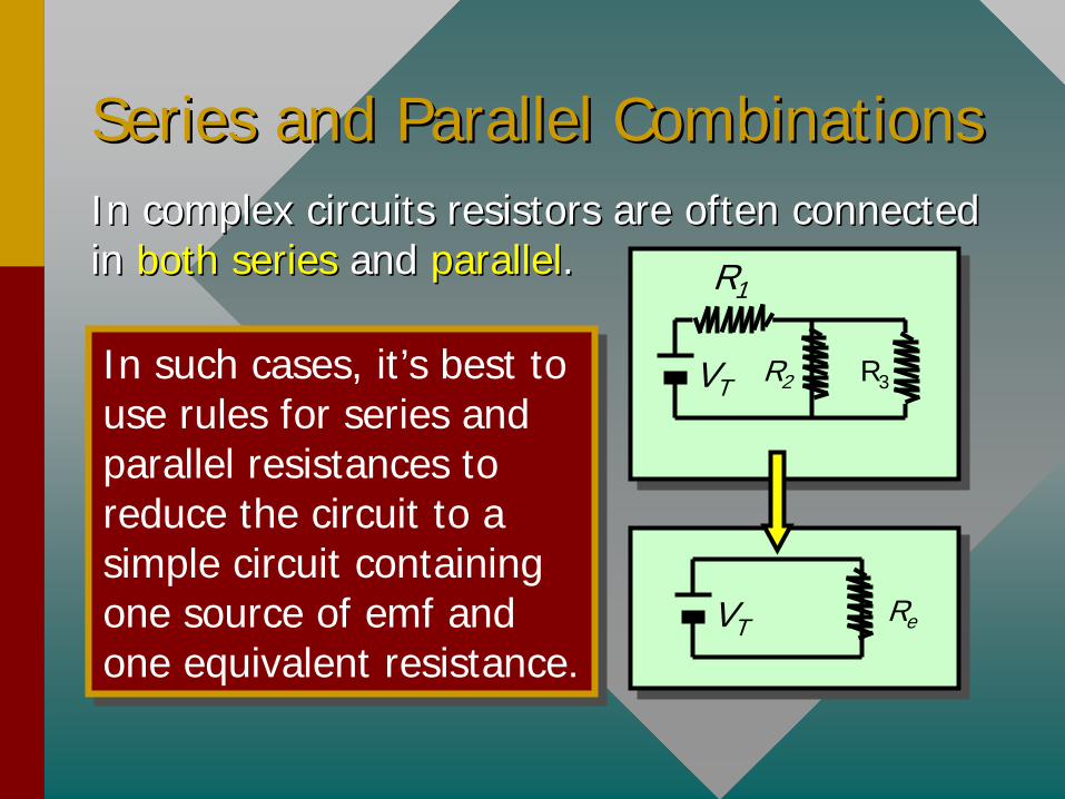
Series and Parallel CombinationsSeries and Parallel CombinationsIn complex circuits resistors are often connected In complex circuits resistors are often connected inin bothboth seriesseries and and parallelparallel. .
VT R2 R3
R1
In such cases, it’s best to use rules for series and parallel resistances to reduce the circuit to a simple circuit containing one source of emf and one equivalent resistance.
In such cases, it’s best to use rules for series and parallel resistances to reduce the circuit to a simple circuit containing one source of emf and one equivalent resistance.
VT Re
Example 4.Example 4. Find the equivalent resistance for Find the equivalent resistance for the circuit drawn below (assume Vthe circuit drawn below (assume VTT = 12 V).= 12 V).
3,6(3 )(6 ) 23 6
R
RRee = 4 = 4
+ 2 + 2
Re = 6 Re = 6
VT 3 6
4
12 V 2
4
6 12 V
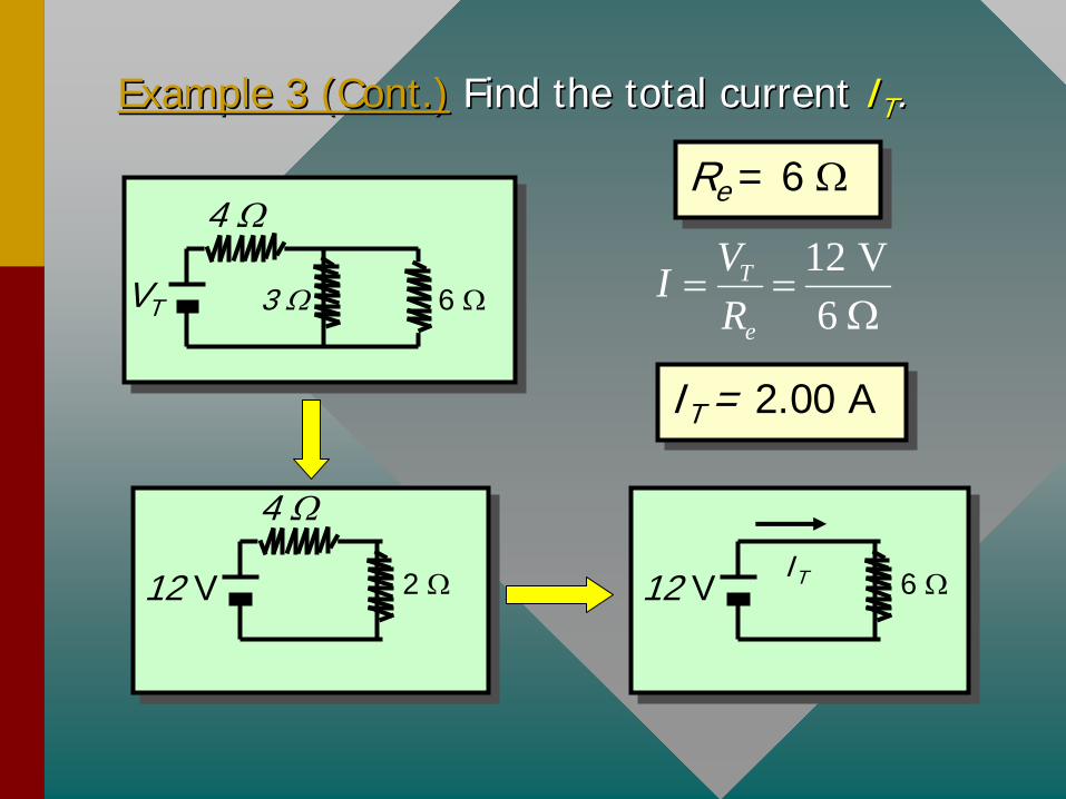
Example 3 (Cont.)Example 3 (Cont.) Find the total current Find the total current IITT ..
VT 3 6
4
12 V 2
4
6 12 VIT
Re = 6 Re = 6
IT = 2.00 AIT = 2.00 A
12 V6
T
e
VIR
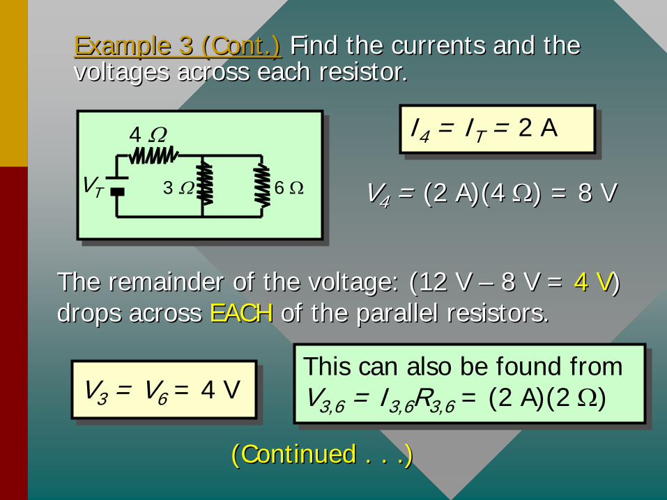
Example 3 (Cont.)Example 3 (Cont.) Find the currents and the Find the currents and the voltages across each resistorvoltages across each resistor
I4 = IT = 2 AI4 = IT = 2 A
VV44 = = (2 A)(4 (2 A)(4 ) = 8 V) = 8 V
The remainder of the voltage: (12 V The remainder of the voltage: (12 V –– 8 V = 8 V = 4 V4 V) ) drops across drops across EACH EACH of the parallel resistors.of the parallel resistors.
V3 = V6 = 4 VV3 = V6 = 4 VThis can also be found from V3,6 = I3,6 R3,6 = (2 A)(2 ) This can also be found from V3,6 = I3,6 R3,6 = (2 A)(2 )
VT 3 6
4
(Continued . . .)(Continued . . .)
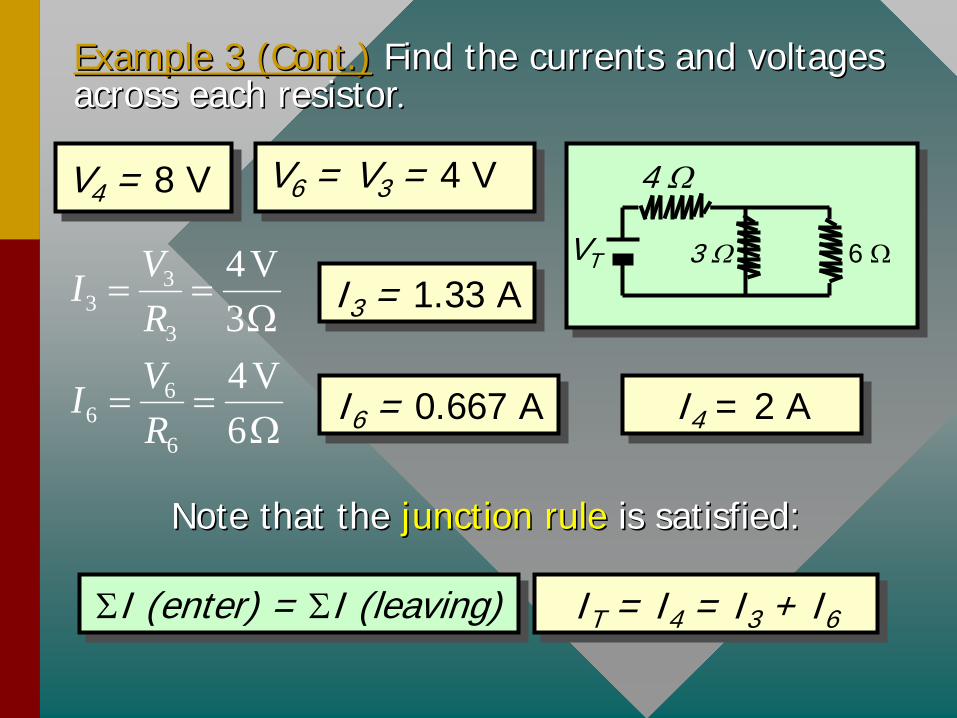
Example 3 (Cont.)Example 3 (Cont.) Find the currents and voltages Find the currents and voltages across each resistoracross each resistor
V6 = V3 = 4 VV6 = V3 = 4 VV4 = 8 VV4 = 8 V
VT 3 6
4
33
3
4V3
VIR
I3 = 1.33 AI3 = 1.33 A
66
6
4V6
VIR
I6 = 0.667 AI6 = 0.667 A I4 = 2 AI4 = 2 A
Note that the Note that the junction rulejunction rule is satisfied:is satisfied:
IT = I4 = I3 + I6IT = I4 = I3 + I6I (enter) = I (leaving)I (enter) = I (leaving)
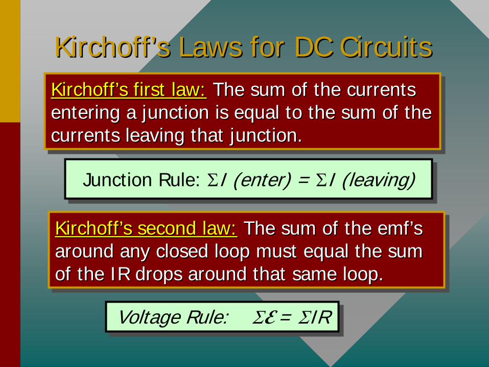
KirchoffKirchoff’’ss Laws for DC CircuitsLaws for DC CircuitsKirchoff’s first law: The sum of the currents entering a junction is equal to the sum of the currents leaving that junction.
KirchoffKirchoff’’ss first law:first law: The sum of the currents The sum of the currents entering a junction is equal to the sum of the entering a junction is equal to the sum of the currents leaving that junction.currents leaving that junction.
Kirchoff’s second law: The sum of the emf’s around any closed loop must equal the sum of the IR drops around that same loop.
KirchoffKirchoff’’ss second law:second law: The sum of the The sum of the emfemf’’ss around any closed loop must equal the sum around any closed loop must equal the sum of the IR drops around that same loop.of the IR drops around that same loop.
Junction Rule: I (enter) = I (leaving)Junction Rule: I (enter) = I (leaving)
Voltage Rule: E = IRVoltage Rule: E = IR

Sign Conventions for Sign Conventions for EmfEmf’’ss
When applying When applying KirchoffKirchoff’’ss laws you must laws you must assume a consistent, positive assume a consistent, positive tracing direction.tracing direction.
When applying the When applying the voltage rulevoltage rule, , emfemf’’ss are are positivepositive if normal output direction of the emf is if normal output direction of the emf is withwith the assumed tracing direction.the assumed tracing direction.
If tracing from If tracing from A to BA to B, this , this emf is considered emf is considered positivepositive.. E
A B++
If tracing from If tracing from B to AB to A, this , this emf is considered emf is considered negativenegative.. E
A B++
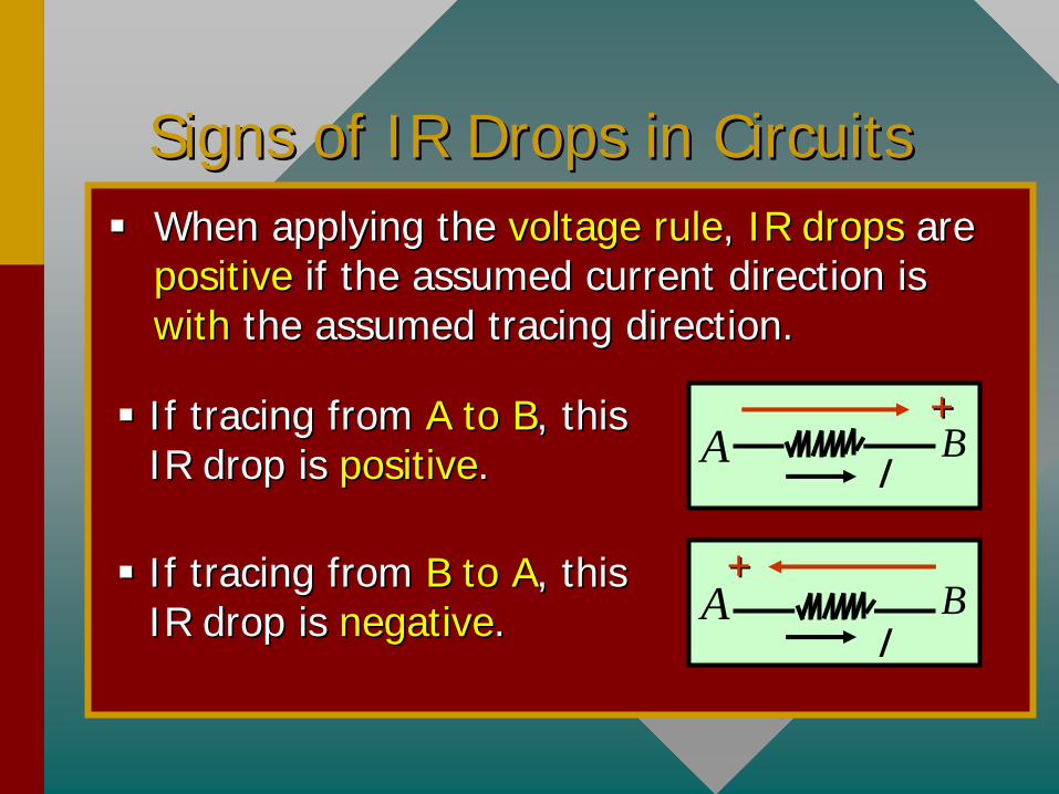
Signs of IR Drops in CircuitsSigns of IR Drops in Circuits
When applying the When applying the voltage rulevoltage rule, , IR dropsIR drops are are positivepositive if the assumed current direction is if the assumed current direction is withwith the assumed tracing direction.the assumed tracing direction.
If tracing from If tracing from A to BA to B, this , this IR drop is IR drop is positivepositive..
If tracing from If tracing from B to AB to A, this , this IR drop is IR drop is negativenegative..
IA B++
IA B
++
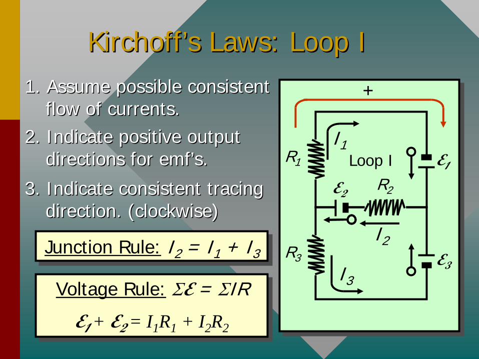
KirchoffKirchoff’’ss Laws: Loop ILaws: Loop I
R3
R1
R2E2
E1
E3
1. Assume possible consistent 1. Assume possible consistent flow of currents.flow of currents.
2. Indicate positive output 2. Indicate positive output directions for directions for emfemf’’ss..
3. Indicate consistent tracing 3. Indicate consistent tracing direction. (clockwise)direction. (clockwise)
+
Loop II1
I2
I3
Junction Rule: I2 = I1 + I3Junction Rule: I2 = I1 + I3
Voltage Rule: E = IR
E1 + E2
= I1 R1 + I2 R2
Voltage Rule: E = IR
E1 + E2
= I1 R1 + I2 R2
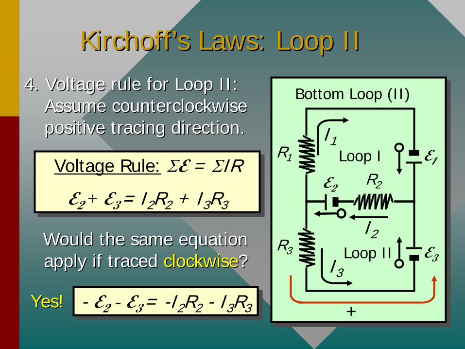
KirchoffKirchoff’’ss Laws: Loop IILaws: Loop II4. Voltage rule for Loop II: 4. Voltage rule for Loop II:
Assume counterclockwise Assume counterclockwise positive tracing direction.positive tracing direction.
Voltage Rule: E = IR
E2 + E3
= I2 R2 + I3 R3
Voltage Rule: E = IR
E2 + E3
= I2R2 + I3R3
R3
R1
R2E2
E1
E3
Loop II1
I2
I3Loop II
Bottom Loop (II)
+
Would the same equation Would the same equation apply if traced apply if traced clockwiseclockwise??
- E2
- E3 = -I2 R2 - I3 R3 - E2
- E3 = -I2R2 - I3R3Yes!Yes!
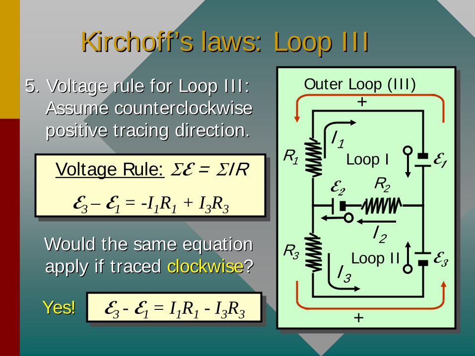
KirchoffKirchoff’’ss laws: Loop IIIlaws: Loop III5. Voltage rule for Loop III: 5. Voltage rule for Loop III:
Assume counterclockwise Assume counterclockwise positive tracing direction.positive tracing direction.
Voltage Rule: E = IR
E3 – E1 = -I1 R1 + I3 R3
Voltage Rule: E = IR
E3 – E1 = -I1 R1 + I3 R3
Would the same equation Would the same equation apply if traced apply if traced clockwiseclockwise??
E3 - E1 = I1 R1 - I3 R3E3 - E1 = I1 R1 - I3 R3Yes!Yes!
R3
R1
R2E2
E1
E3
Loop II1
I2
I3Loop II
Outer Loop (III)
+
+
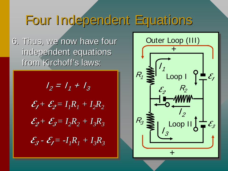
Four Independent EquationsFour Independent Equations6. Thus, we now have four 6. Thus, we now have four
independent equations independent equations from from KirchoffKirchoff’’ss laws:laws:
R3
R1
R2E2
E1
E3
Loop II1
I2
I3Loop II
Outer Loop (III)
+
+
II22 = I= I11 + I+ I33
EE1 1 + + EE22
= I= I11 RR11 + I+ I22 RR22
EE2 2 + + EE33
= I= I22 RR22 + I+ I33 RR33
EE3 3 -- EE11
= = --II11 RR11 + I+ I33 RR33

Example 4.Example 4. Use Use KirchoffKirchoff’’ss laws to find the laws to find the currents in the circuit drawn to the right.currents in the circuit drawn to the right.
10
12 V
6 V
20
5 Junction Rule: I2 + I3 = I1Junction Rule: I2 + I3 = I1
12 V = (5 12 V = (5 ))II11 + (10+ (10 ))II22
Voltage Rule: Voltage Rule: E E = = IRIR
Consider Consider Loop ILoop I tracing tracing clockwiseclockwise to obtain:to obtain:
Recalling that Recalling that V/V/
= A= A, gives , gives
5I1 + 10I2 = 12 A5I1 + 10I2 = 12 A
I1
I2
I3
+
Loop I
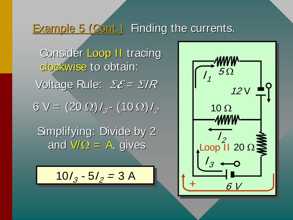
Example 5 (Cont.)Example 5 (Cont.) Finding the currents.Finding the currents.
6 V = (20 6 V = (20 ))II33 -- (10(10 ))II22
Voltage Rule: Voltage Rule: E E = = IRIR
Consider Consider Loop IILoop II tracing tracing clockwiseclockwise to obtain:to obtain:
10I3 - 5I2 = 3 A10I3 - 5I2 = 3 A
10
12 V
6 V
20
5 I1
I2
I3
+
Loop IISimplifying: Divide by 2 Simplifying: Divide by 2
and and V/V/
= A= A, gives , gives
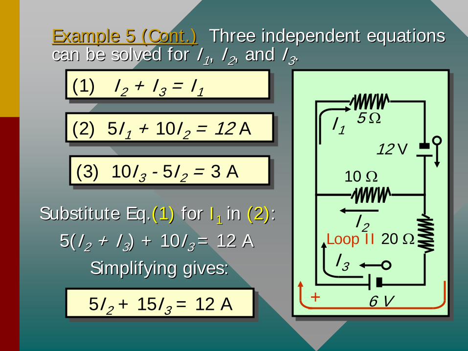
Example 5 (Cont.)Example 5 (Cont.) Three independent equations Three independent equations can be solved for can be solved for II11 , , II22 , and , and II33 ..
(3) 10I3 - 5I2 = 3 A(3) 10I3 - 5I2 = 3 A 10
12 V
6 V
20
5 I1
I2
I3
+
Loop II
(1) I2 + I3 = I1(1) I2 + I3 = I1
(2) 5I1 + 10I2 = 12 A(2) 5I1 + 10I2 = 12 A
Substitute Eq.Substitute Eq.(1)(1) for for II11 in in (2)(2)::5(5(II22 + I+ I33 ) + 10) + 10II33 = 12 A= 12 A
SimplifyingSimplifying gives:gives:
5I2 + 15I3 = 12 A5I2 + 15I3 = 12 A
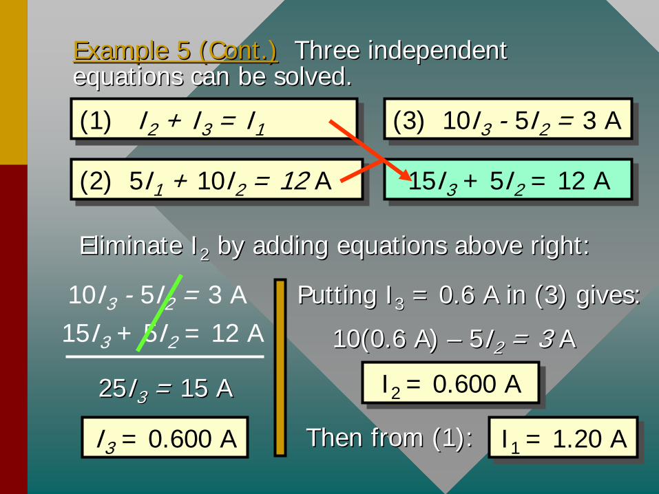
Example 5 (Cont.)Example 5 (Cont.) Three independent Three independent equations can be solved.equations can be solved.
(3) 10I3 - 5I2 = 3 A(3) 10I3 - 5I2 = 3 A(1) I2 + I3 = I1(1) I2 + I3 = I1
(2) 5I1 + 10I2 = 12 A(2) 5I1 + 10I2 = 12 A 15I3 + 5I2 = 12 A15I3 + 5I2 = 12 A
Eliminate IEliminate I22 by adding equations above right:by adding equations above right:
10I3 - 5I2 = 3 A15I3 + 5I2 = 12 A
2525II33 = = 1515 AA
I3 = 0.600 A
Putting IPutting I33 = 0.6 A in (3) gives:= 0.6 A in (3) gives:
10(0.6 A) 10(0.6 A) –– 55II22 = 3= 3 AA
I2 = 0.600 AI2 = 0.600 A
Then from (1):Then from (1): I1 = 1.20 AI1 = 1.20 A
Summary of Formulas:Summary of Formulas:
Resistance Rule: Re = R
Voltage Rule: E = IR
: Current IR
E
Rules for a simple, single loop circuit containing a source of emf and resistors.
Rules for a simple, single loop circuit containing a source of emf and resistors.
2
3 V +-
+
-18 V
A
C B
D
3
Single Loop
Summary (Cont.)Summary (Cont.)
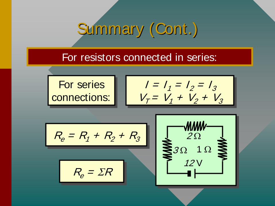
For resistors connected in series:
Re = R1 + R2 + R3Re = R1 + R2 + R3
For series connections: For series
connections:I = I1 = I2 = I3
VT = V1 + V2 + V3
I = I1 = I2 = I3 VT = V1 + V2 + V3
Re = RRe = R
2
12 V1 3
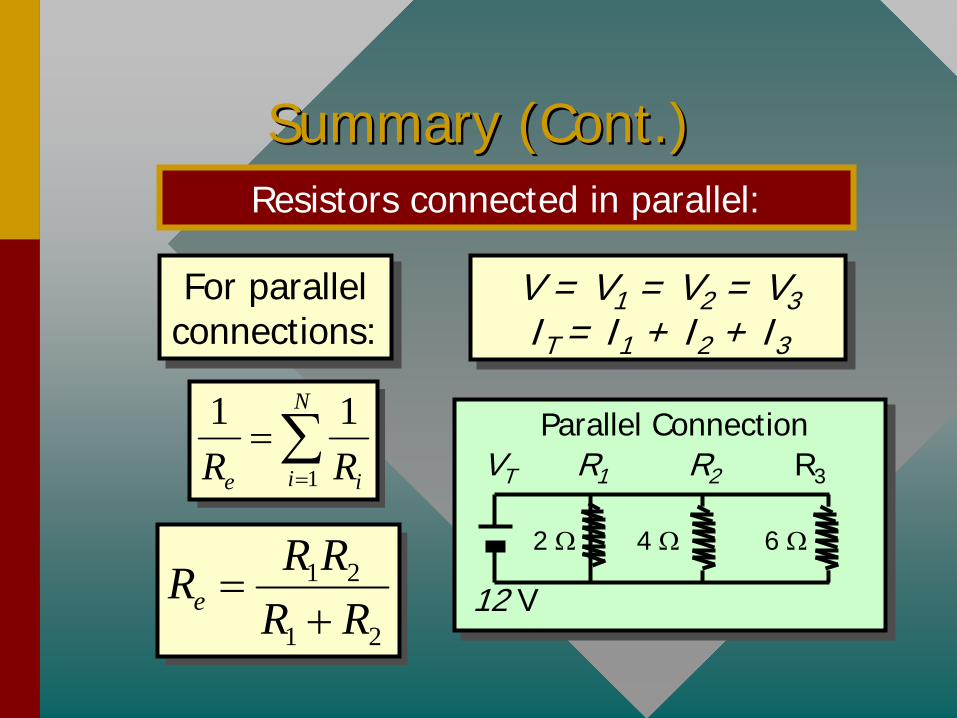
Summary (Cont.)Summary (Cont.)Resistors connected in parallel:
For parallel connections: For parallel
connections:V = V1 = V2 = V3 IT = I1 + I2 + I3
V = V1 = V2 = V3 IT = I1 + I2 + I3
1 2
1 2e
R RRR R
1
1 1N
ie iR R
R3R2
12 V
R1
2 4 6
VT
Parallel Connection
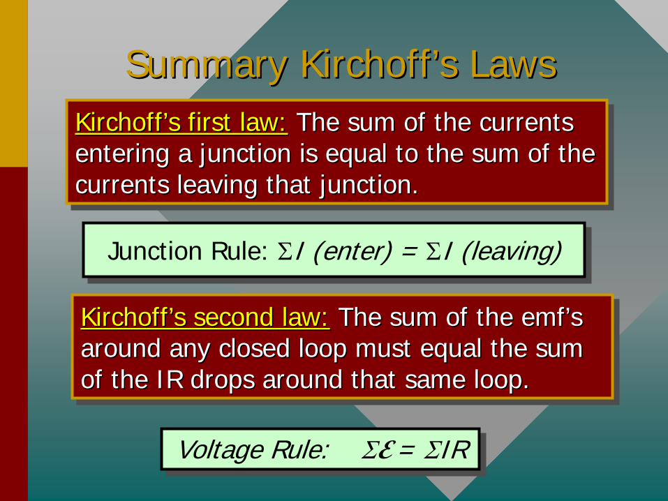
Summary Summary KirchoffKirchoff’’ss LawsLawsKirchoff’s first law: The sum of the currents entering a junction is equal to the sum of the currents leaving that junction.
KirchoffKirchoff’’ss first law:first law: The sum of the currents The sum of the currents entering a junction is equal to the sum of the entering a junction is equal to the sum of the currents leaving that junction.currents leaving that junction.
Kirchoff’s second law: The sum of the emf’s around any closed loop must equal the sum of the IR drops around that same loop.
KirchoffKirchoff’’ss second law:second law: The sum of the The sum of the emfemf’’ss around any closed loop must equal the sum around any closed loop must equal the sum of the IR drops around that same loop.of the IR drops around that same loop.
Junction Rule: I (enter) = I (leaving)Junction Rule: I (enter) = I (leaving)
Voltage Rule: E = IRVoltage Rule: E = IR
CONCLUSION: Chapter 28ACONCLUSION: Chapter 28A Direct Current CircuitsDirect Current Circuits