
Chapter 27: Optical Instruments - Croom · PDF fileCopyright © 2010 Pearson Education,...
33
Copyright © 2010 Pearson Education, Inc. All rights reserved. This material is protected under all copyright laws as they currently exist. No portion of this material may be reproduced, in any form or by any means, without permission in writing from the publisher. 27 – 1 Chapter 27: Optical Instruments Answers to Even-Numbered Conceptual Questions 2. No. The lens will still show a complete image, though you may have to move your head more from side to side to see it all. 4. The reason things look blurry underwater is that there is much less refraction of light when it passes from water to your cornea than when it passes from air to your cornea. Therefore, your eyes simply aren’t converging light enough when they are in water. Since farsightedness is caused when your eyes don’t converge light as much as they should (see Figure 27-11), this can be considered as an extreme case of farsightedness. 6. Yes, it matters. A simple magnifier is nothing more than a convex lens. As we can see from Figure 26-35, a convex lens forms an enlarged (magnified) image only when the object is closer to the lens than its focal length. 8. No. Chromatic aberration occurs in lenses because light of different frequency refracts by different amounts. In the case of a mirror, however, all light—regardless of its frequency—obeys the same simple law of reflection; namely, that the angle of reflection is equal to the angle of incidence. Since light of all colors is bent in the same way by a mirror, there is no chromatic aberration. Solutions to Problems and Conceptual Exercises 2. Picture the Problem: The figure shows a 1.9-meter-tall person (represented by the arrow) standing d o = 3.2 meters from the eye lens. The image is formed on the retina d i = 2.5 cm from the lens. Strategy: Use equations 26-17 and 26-18 to calculate the image height. Solution: 1. (a) Combine equations 26-17 and 26-18 to calculate the image height: i i o o o 0.025 m 1.9 m 1.5 cm 3.2 m d h mh h d 2. (b) Change the object distance to 4.2 m: i 0.025 m 1.9 m 1.1 cm 4.2 m h Insight: As an object moves away from you, the size of the image it forms on your retina decreases.
Transcript of Chapter 27: Optical Instruments - Croom · PDF fileCopyright © 2010 Pearson Education,...
Copyright © 2010 Pearson Education, Inc. All rights reserved. This material is protected under all copyright laws as they currently exist. No portion of this material may be reproduced, in any form or by any means, without permission in writing from the publisher.
27 – 1
Chapter 27: Optical Instruments
Answers to Even-Numbered Conceptual Questions 2. No. The lens will still show a complete image, though you may have to move your head more from side to
side to see it all.
4. The reason things look blurry underwater is that there is much less refraction of light when it passes from water to your cornea than when it passes from air to your cornea. Therefore, your eyes simply aren’t converging light enough when they are in water. Since farsightedness is caused when your eyes don’t converge light as much as they should (see Figure 27-11), this can be considered as an extreme case of farsightedness.
6. Yes, it matters. A simple magnifier is nothing more than a convex lens. As we can see from Figure 26-35, a convex lens forms an enlarged (magnified) image only when the object is closer to the lens than its focal length.
8. No. Chromatic aberration occurs in lenses because light of different frequency refracts by different amounts. In the case of a mirror, however, all light—regardless of its frequency—obeys the same simple law of reflection; namely, that the angle of reflection is equal to the angle of incidence. Since light of all colors is bent in the same way by a mirror, there is no chromatic aberration.
Solutions to Problems and Conceptual Exercises
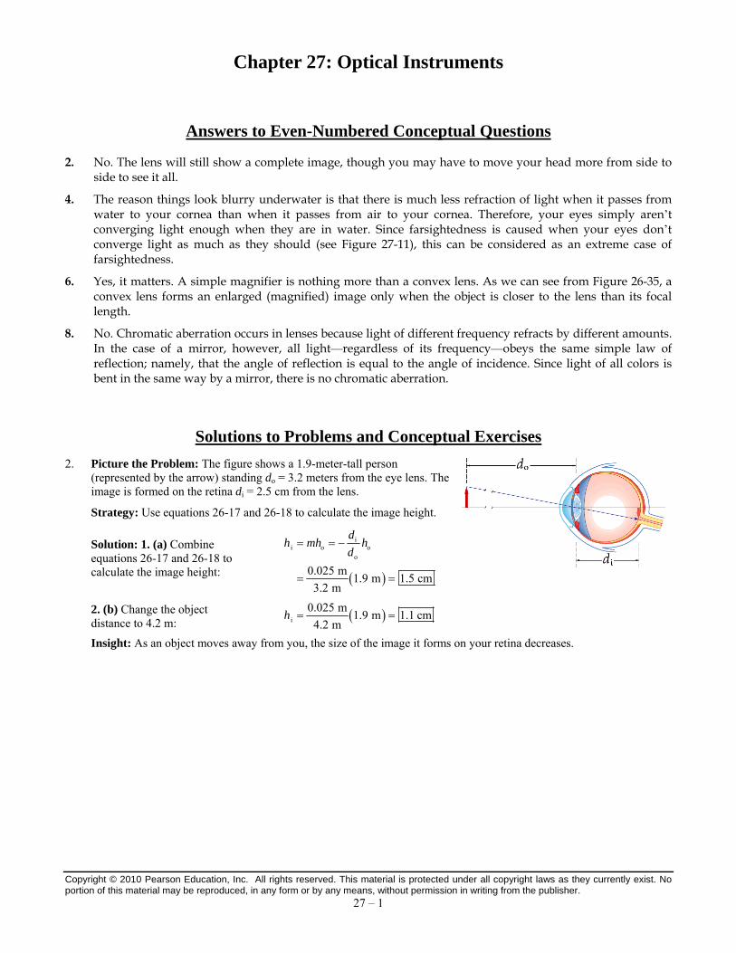
2. Picture the Problem: The figure shows a 1.9-meter-tall person (represented by the arrow) standing do = 3.2 meters from the eye lens. The image is formed on the retina di = 2.5 cm from the lens.
Strategy: Use equations 26-17 and 26-18 to calculate the image height.
Solution: 1. (a) Combine equations 26-17 and 26-18 to calculate the image height:
ii o o
o
0.025 m1.9 m 1.5 cm
3.2 m
dh mh h
d
2. (b) Change the object distance to 4.2 m:
i
0.025 m1.9 m 1.1 cm
4.2 mh
Insight: As an object moves away from you, the size of the image it forms on your retina decreases.
Chapter 27: Optical Instruments James S. Walker, Physics, 4th Edition
Copyright © 2010 Pearson Education, Inc. All rights reserved. This material is protected under all copyright laws as they currently exist. No portion of this material may be reproduced, in any form or by any means, without permission in writing from the publisher.
27 – 2
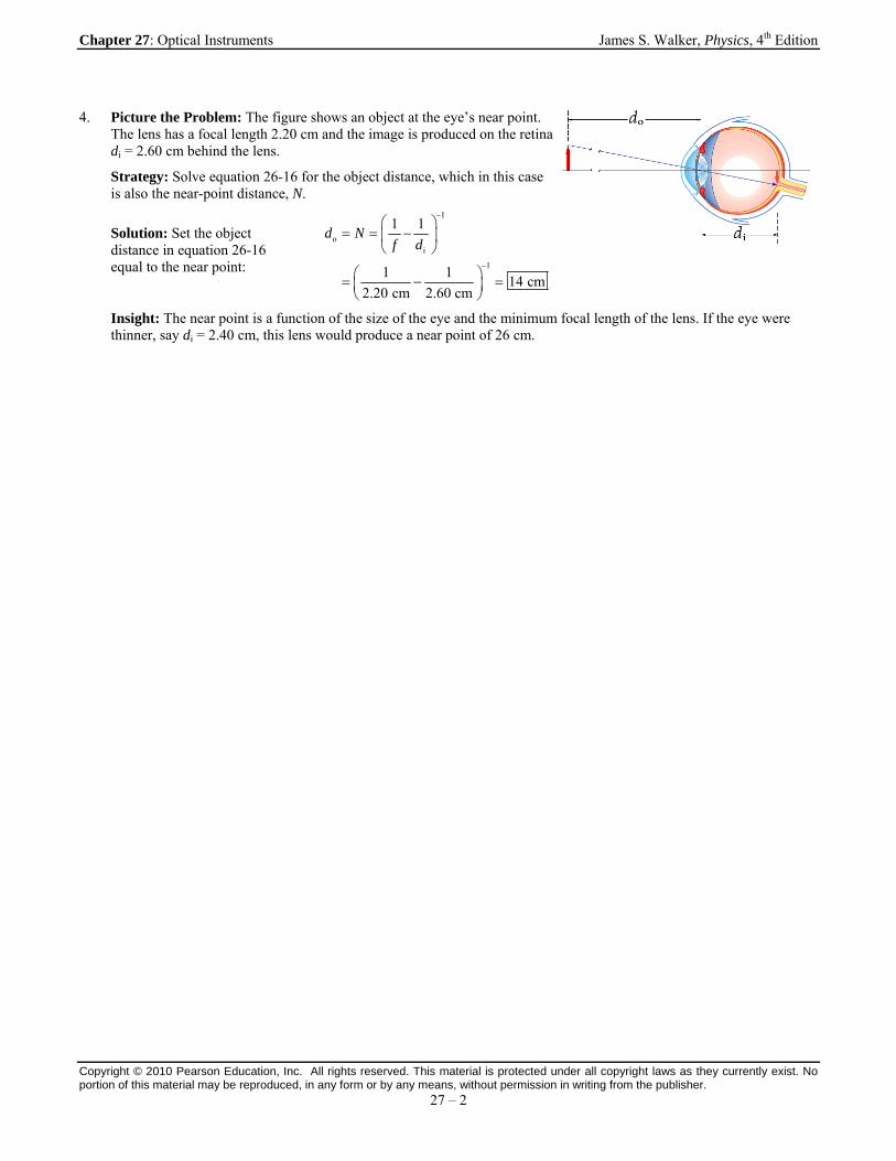
4. Picture the Problem: The figure shows an object at the eye’s near point. The lens has a focal length 2.20 cm and the image is produced on the retina di = 2.60 cm behind the lens.
Strategy: Solve equation 26-16 for the object distance, which in this case is also the near-point distance, N.
Solution: Set the object distance in equation 26-16 equal to the near point:
1
oi
1
1 1
1 114 cm
2.20 cm 2.60 cm
d Nf d
Insight: The near point is a function of the size of the eye and the minimum focal length of the lens. If the eye were thinner, say di = 2.40 cm, this lens would produce a near point of 26 cm.

Chapter 27: Optical Instruments James S. Walker, Physics, 4th Edition
Copyright © 2010 Pearson Education, Inc. All rights reserved. This material is protected under all copyright laws as they currently exist. No portion of this material may be reproduced, in any form or by any means, without permission in writing from the publisher.
27 – 3
6. Picture the Problem: The f-number of a camera lens is the ratio of the focal length to the aperture diameter.
Strategy: Divide the focal length by the f-number to calculate the aperture diameter for each lens. Then rank the lenses by aperture diameter.
Solution: 1. Calculate the diameter of lens A:
150 mm130 mm
-number 1.2
fD
f
2. Calculate the diameter of lens B:
150 mm27 mm
-number 5.6
fD
f
3. Calculate the diameter of lens C:
35 mm29 mm
-number 1.2
fD
f
4. Calculate the diameter of lens D:
35 mm6.3 mm
-number 5.6
fD
f
5. Rank the lenses from largest to smallest diameter: A, C, B, D
Insight: Note that lenses B and C have nearly the same diameters.
8. Picture the Problem: The f-number of a camera is the ratio of the focal length to the aperture diameter.
Strategy: The aperture setting is the f-number of the camera’s optical system. Divide the focal length by the f-number to calculate the aperture diameter for each lens.
Solution: 1. (a) The smallest f-number gives the largest diameter because the diameter is inversely proportional to the f-number. Therefore, an f-number of 2.8 corresponds to the largest diameter.
2. (b) Calculate the diameter for f/2.8:
55 mm20 mm
-number 2.8
fD
f
3. Calculate the diameter for f/4:
55 mm14 mm
4D
4. Calculate the diameter for f/8:
55 mm6.9 mm
8D
5. Calculate the diameter for f/11:
55 mm5.0 mm
11D
6. Calculate the diameter for f/16:
55 mm3.4 mm
16D
Insight: As the aperture setting increases, the aperture diameter decreases proportionately.

Chapter 27: Optical Instruments James S. Walker, Physics, 4th Edition
Copyright © 2010 Pearson Education, Inc. All rights reserved. This material is protected under all copyright laws as they currently exist. No portion of this material may be reproduced, in any form or by any means, without permission in writing from the publisher.
27 – 4
10. Picture the Problem: The figure shows a 2.0-m-tall object at a distance do from the camera lens. A 36-mm-tall image is produced on the film by the lens.
Strategy: Use equation 26-15 to write the image distance in terms of the object distance and the object and image heights. Insert this expression into equation 26-16 and solve for the object distance.
Solution: 1. Solve equation 26-15 for the image distance:
ii o
o
hd d
h
2. Insert the image distance into equation 26-16:
o o
i o i o o o i
1 1 1 1 11
h h
f d d h d d d h
3. Solve for the object distance: o
oi
2.0 m1 0.150 m 1 8.5 m
0.036 m
hd f
h
Insight: If the person stands closer than 8.2 m the film will not be able to contain his full image.
12. Picture the Problem: The proper amount of light exposes the film when the aperture is set at f /8 and the shutter speed is 1/125. Changing the aperture setting will require a change of the shutter speed to maintain the film exposure.
Strategy: Calculate the ratio of the aperture areas from the f-numbers (aperture diameters). Because increasing the aperture diameter lets in more light, the shutter speed must be decreased. It should be decreased in proportion to the increase in aperture area. Divide the shutter speed by the ratio of aperture areas to calculate the final shutter speed. Set the shutter speed to the nearest standard setting as discussed in section 27-1.
Solution: 1. Calculate the ratio of aperture areas:
2 2212.42.4 4
2 218 84
2.4 811.11
2.48
fDA
A D f
2. Divide the shutter speed by the ratio of aperture areas:
2.4
8
1 1 1 1 1s s s s
125 125 11.11 1390 1000
A
A
Insight: Because the shutter speed is slightly slower than the desired speed, the image will be somewhat brighter than at the initial setting.
14. Picture the Problem: A camera produces a correctly exposed photograph with a shutter speed of 1/125 s and an f-stop of f /5.6. To take a sharp photo of moving horses, it is desirable to use the fastest shutter speed, which will require a change in the f-stop setting.
Strategy: Because using a shorter exposure time decreases the amount of light entering the camera, the area of the aperture must be increased to compensate. Since the f-number is inversely proportional to the aperture diameter, the smallest f-number is needed. To calculate the correct shutter speed, first calculate the proportional increase in aperture area when switching from f /5.6 to the final f-number. Divide the shutter speed by this relative increase in area and round to the nearest available shutter speed.
Solution: 1. (a) Because
1
-numberD
f , the smallest f-number gives the largest aperture diameter, and therefore the
largest aperture area. The f-stop should be set to 2.
2. (b) Calculate the ratio of aperture area:
22 21ff 42 2 21
i i4
2 5.67.8
25.6
fDA
A D f
3. (c) Divide the shutter speed by the ratio of aperture area:
1 1 1 1s s
125 7.8 975 1000t
Chapter 27: Optical Instruments James S. Walker, Physics, 4th Edition
Copyright © 2010 Pearson Education, Inc. All rights reserved. This material is protected under all copyright laws as they currently exist. No portion of this material may be reproduced, in any form or by any means, without permission in writing from the publisher.
27 – 5
Insight: Because the shutter speed has decreased by a factor of eight, the horses will only move one-eighth the distance while the camera shutter is open. This will greatly decrease the blurring caused by the motion of the horse.

Chapter 27: Optical Instruments James S. Walker, Physics, 4th Edition
Copyright © 2010 Pearson Education, Inc. All rights reserved. This material is protected under all copyright laws as they currently exist. No portion of this material may be reproduced, in any form or by any means, without permission in writing from the publisher.
27 – 6
16. Picture the Problem: Two professors are stranded on a deserted island. Both wear glasses, though one is nearsighted and the other is farsighted.
Strategy: Recall the lens types used to correct vision defects, and note that only a converging lens can focus the Sun’s rays in order to start a fire.
Solution: 1. (a) The farsighted professor’s glasses are converging, and therefore they are the ones that should be used to start a fire.
2. (b) The best explanation is II. A farsighted person can’t focus close, so the glasses to correct that person’s vision are converging. A converging lens is what you need to concentrate the rays of the Sun. Statement I is incorrect because diverging lenses are used to correct nearsightedness.
Insight: The diverging lenses used by the nearsighted professor aren’t very useful for daily life on the island, but they would help him spot a distant ship before lighting a signal fire!
18. Picture the Problem: An umpire wears glasses that make his eyes look smaller than they actually are.
Strategy: Note the magnification of the virtual images produced by converging and diverging lenses when each is held close (less than a focal length) to an object. Also recall that converging lenses correct farsightedness and diverging lenses correct nearsightedness.
Solution: A concave lens always forms an image smaller than the object, as can be seen in Figure 26-34. A convex lens, on the other hand, produces an enlarged image when the object is closer than the focal point, as shown in Figure 26-35 (b). Therefore, the person is wearing glasses that diverge, like a concave lens. Such lenses are used to correct nearsightedness (see Figure 27-7), and hence we conclude that the person is nearsighted.
Insight: Some people who need vision correction are farsighted and wear converging lenses. When you encounter a farsighted person who is wearing glasses, note how they make the eyes look larger than they actually are.
Chapter 27: Optical Instruments James S. Walker, Physics, 4th Edition
Copyright © 2010 Pearson Education, Inc. All rights reserved. This material is protected under all copyright laws as they currently exist. No portion of this material may be reproduced, in any form or by any means, without permission in writing from the publisher.
27 – 7
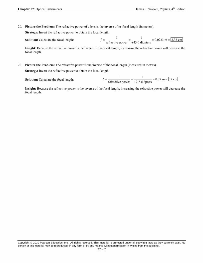
20. Picture the Problem: The refractive power of a lens is the inverse of its focal length (in meters).
Strategy: Invert the refractive power to obtain the focal length.
Solution: Calculate the focal length:
1 10.0233 m 2.33 cm
refractive power 43.0 dioptersf
Insight: Because the refractive power is the inverse of the focal length, increasing the refractive power will decrease the focal length.
22. Picture the Problem: The refractive power is the inverse of the focal length (measured in meters).
Strategy: Invert the refractive power to obtain the focal length.
Solution: Calculate the focal length:
1 10.37 m 37 cm
refractive power 2.7 dioptersf
Insight: Because the refractive power is the inverse of the focal length, increasing the refractive power will decrease the focal length.

Chapter 27: Optical Instruments James S. Walker, Physics, 4th Edition
Copyright © 2010 Pearson Education, Inc. All rights reserved. This material is protected under all copyright laws as they currently exist. No portion of this material may be reproduced, in any form or by any means, without permission in writing from the publisher.
27 – 8
24. Picture the Problem: The image shows two thin lenses with refractive powers of +4.00 diopters and −2.35 diopters in contact with each other. Light from an object will produce an image from these two lenses at a distance determined by their effective refractive power.
Strategy: Use the lens equation (equation 26-16) to calculate the image distance from the first lens. Subtract the image distance from the separation distance (zero) between the two lenses to calculate the object distance for the second lens. Solve the lens equation for the final image distance. Use the initial object distance and the final image distance in the lens equation to calculate the effective focal length. Set the inverse of the focal lengths equal to the refractive powers.
Solution: 1. Solve the lens equation for the image distance of the first lens:
1
i11 o1
1 1d
f d
2. Set the object distance for the second lens as the negative of the image distance from the first lens:
1
o2 i11 o1
1 10d d
f d
3. Solve the lens equation for the image distance of the second lens:
11
i22 o2 2 1 o1
1 1 1 1 1d
f d f f d
4. Insert the initial object and the final image into the lens equation and solve for the effective focal length:
eff o1 i2 o1 2 1 o1 2 1
1 1 1 1 1 1 1 1 1
2.35 diopters + 4.00 diopters = 1.65 diopters
f d d d f f d f f
Insight: When thin lenses are placed in contact with each other, their effective refractive power is the sum of the refractive powers of each lens independently.

Chapter 27: Optical Instruments James S. Walker, Physics, 4th Edition
Copyright © 2010 Pearson Education, Inc. All rights reserved. This material is protected under all copyright laws as they currently exist. No portion of this material may be reproduced, in any form or by any means, without permission in writing from the publisher.
27 – 9
26. Picture the Problem: The relaxed eye focuses on distant objects. In order to focus on close objects, the eye is able to change the shape of its lens and therefore change its refractive power by 16 diopters.
Strategy: Calculate the refractive power of the relaxed eye from the inverse of the focal length. Add the 16 diopters to the refractive power and take the inverse to calculate the new focal length.
Solution: 1. (a) The light rays from a nearby object must bend more sharply when traveling from the object to the retina, so the eye’s refractive power must increase.
2. (b) Calculate the relaxed refractive power: relaxed
relaxed
1 1refractive power 58.8 diopters
0.017 mf
3. Add the change in refractive power and invert to calculate the close focal length: close
close
1 11.3 cm
refractive power 58.8 16 dioptersf
Insight: The focal length of the eye ranges from 1.3 cm to 1.7 cm.
Chapter 27: Optical Instruments James S. Walker, Physics, 4th Edition
Copyright © 2010 Pearson Education, Inc. All rights reserved. This material is protected under all copyright laws as they currently exist. No portion of this material may be reproduced, in any form or by any means, without permission in writing from the publisher.
27 – 10
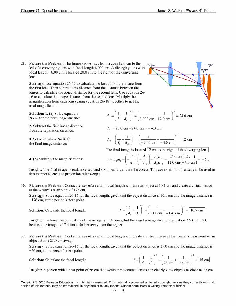
28. Picture the Problem: The figure shows rays from a coin 12.0 cm to the left of a converging lens with focal length 8.000 cm. A diverging lens with focal length − 6.00 cm is located 20.0 cm to the right of the converging lens.
Strategy: Use equation 26-16 to calculate the location of the image from the first lens. Then subtract this distance from the distance between the lenses to calculate the object distance for the second lens. Use equation 26-16 to calculate the image distance from the second lens. Multiply the magnification from each lens (using equation 26-18) together to get the total magnification.
Solution: 1. (a) Solve equation 26-16 for the first image distance:
1 1
i11 o1
1 1 1 124.0 cm
8.000 cm 12.0 cmd
f d
2. Subtract the first image distance from the separation distance: o2 20.0 cm 24.0 cm 4.0 cmd
3. Solve equation 26-16 for the final image distance:
1 1
i22 o2
1 1 1 112 cm
6.00 cm 4.0 cmd
f d
The final image is located 12 cm to the right of the diverging lens .
4. (b) Multiply the magnifications:
i1 i2 i1 i21 2
o1 o2 o1 o2
24.0 cm 12 cm6.0
12.0 cm 4.0 cm
d d d dm m m
d d d d
Insight: The final image is real, inverted, and six times larger than the object. This combination of lenses can be used in this manner to create a projection microscope.
30. Picture the Problem: Contact lenses of a certain focal length will take an object at 10.1 cm and create a virtual image at the wearer’s near point of 176 cm.
Strategy: Solve equation 26-16 for the focal length, given that the object distance is 10.1 cm and the image distance is −176 cm, at the person’s near point.
Solution: Calculate the focal length:
1 1
o i
1 1 1 110.7 cm
10.1 cm 176 cmf
d d
Insight: The linear magnification of the image is 17.4 times, but the angular magnification (equation 27-3) is 1.00, because the image is 17.4 times farther away than the object.
32. Picture the Problem: Contact lenses of a certain focal length will create a virtual image at the wearer’s near point of an object that is 25.0 cm away.
Strategy: Solve equation 26-16 for the focal length, given that the object distance is 25.0 cm and the image distance is −56 cm, at the person’s near point.
Solution: Calculate the focal length:
1 1
o i
1 1 1 145 cm
25 cm 56 cmf
d d
Insight: A person with a near point of 56 cm that wears these contact lenses can clearly view objects as close as 25 cm.

Chapter 27: Optical Instruments James S. Walker, Physics, 4th Edition
Copyright © 2010 Pearson Education, Inc. All rights reserved. This material is protected under all copyright laws as they currently exist. No portion of this material may be reproduced, in any form or by any means, without permission in writing from the publisher.
27 – 11
34. Picture the Problem: This image shows a person wearing glasses D = 2.1 cm in front of his eyes. The focal length of these glasses is such that the virtual image of distance objects is within di +D = 4.5 m of his eyes.
Strategy: Solve equation 26-16 for the focal length, where the object distance is infinite and the image distance is the difference between the wearer’s far point and the distance from his eyes to the glasses.
Solution: Calculate the focal length:
11
o i
1 1 1 1= 4.5 m
4.5 m 0.021 mf
d d
Insight: In this problem the focal length is large enough that the distance from the wearer’s eyes was not significant. However, for smaller focal lengths this distance can be significant.
36. Picture the Problem: The figure shows a person wearing glasses a distance D in front of his eyes. The focal length of the glasses is such that an object do = 25.0 m in front of his eyes produces an image at his far point.
Strategy: Solve equation 26-16 for the focal length, where the object distance is o 25.0 md D and the image distance is
i 2.50 m .d D
Solution: 1. (a) Calculate the focal length for glasses at D = 2.00 cm:
11
o i
1 1 1 12.75 m
25.0 0.0200 m 2.50 0.0200 mf
d d
2. (b) Calculate the focal length for glasses at D = 1.00 cm:
1
1 12.77 m
25.0 0.0100 m 2.50 m 0.0100 mf
Insight: The distance D the glasses are worn from the eye only slightly affects the needed focal length because both the object distance and the far point are very large in comparison to D.

Chapter 27: Optical Instruments James S. Walker, Physics, 4th Edition
Copyright © 2010 Pearson Education, Inc. All rights reserved. This material is protected under all copyright laws as they currently exist. No portion of this material may be reproduced, in any form or by any means, without permission in writing from the publisher.
27 – 12
38. Picture the Problem: The eye can focus on distant objects when it is relaxed. In this condition the refractive power of the eye is a minimum.
Strategy: Calculate the refractive power (using equation 26-16) necessary to create an image of infinitely distant objects on the retina that is a distance of 2.4 cm behind the lens. If the minimum refractive power of the eye is greater than this value, the person is nearsighted; that is, her eyes have sufficient refractive power to focus on nearby objects but not distant objects. Use the minimum refractive power and the image distance to calculate the person’s far point.
Solution: 1. (a) Calculate the minimum refract- tive power to see an infinitely far object:
relaxed o, max i
1 1 1 1 141.7 diopters
0.0240 mf d d
2. Because the patient’s minimum refractive power is 48.5 diopters, the patient is nearsighted.
3. (b) Calculate the patient’s far point:
1 11
o, maxrelaxed i
1 1 148.5 m 15 cm
0.0240 md
f d
Insight: To correct the nearsightedness, the patient needs lenses with a refractive power of 41.7 – 48.5 = – 6.8 diopters.
40. Picture the Problem: Uncle Albert has a near point of 25 cm and a far point of 170 cm. Eyeglasses of the correct refractive power will allow him to clearly see distant objects.
Strategy: Solve equation 26-16 for the refractive power, where the object distance is infinite and the image distance is the difference between Uncle Albert’s far point and the distance from his eyes to the glasses. Then use the refractive power in equation 26-16 to solve for the object distance at which the image would be at Uncle Albert’s near point.
Solution: 1. (a) Calculate the refractive power (R.P.): o i
1 1 1 1 1R.P. 0.60 diopters
1.7 0.020 mf d d
2. (b) Calculate the new near point:
11
oi
1 1 10.60 diopters 27 cm
0.25 0.020 md
f d
Insight: The glasses, in addition to increasing the far point to infinity, increase the near point from 25 cm to 27 cm.
42. Picture the Problem: An object is 4.00 m in front of a converging lens. A diverging lens is placed 36.0 cm behind the converging lens. The lenses produce a real image on the film behind the diverging lens.
Strategy: Use equation 26-16 to calculate the image distance from the first lens. Subtract that distance from the separation distance between the lenses to determine the object distance for the second lens. Then use equation 26-16 again to calculate the final image distance. Multiply the magnifications from each lens (using equation 26-18) to calculate the total magnification.
Solution: 1. Calculate the image distance from the converging lens:
1 1
i11 o1
1 1 1 10.432 m 43.2 cm
0.390 m 4.00 md
f d
2. Find the second object distance: o 36.0 cm 43.2 cm 7.2 cmd
3. Calculate the second image distance:
1 1
i22 o2
1 1 1 130 cm
10.0 cm 7.2 cmd
f d
The film should be placed 30 cm behind the diverging lens.
Chapter 27: Optical Instruments James S. Walker, Physics, 4th Edition
Copyright © 2010 Pearson Education, Inc. All rights reserved. This material is protected under all copyright laws as they currently exist. No portion of this material may be reproduced, in any form or by any means, without permission in writing from the publisher.
27 – 13
4. Calculate the total magnification:
i1 i2 i1 i21 2
o1 o2 o1 o2
0.432 m 25.7 cm0.39
4.00 m 7.2 cm
d d d dm m m
d d d d
Insight: If the diverging lens were not present, the converging lens by itself would have produced a magnification of − 0.15. The addition of the diverging lens increased the magnification and moved the image farther away from the lens.
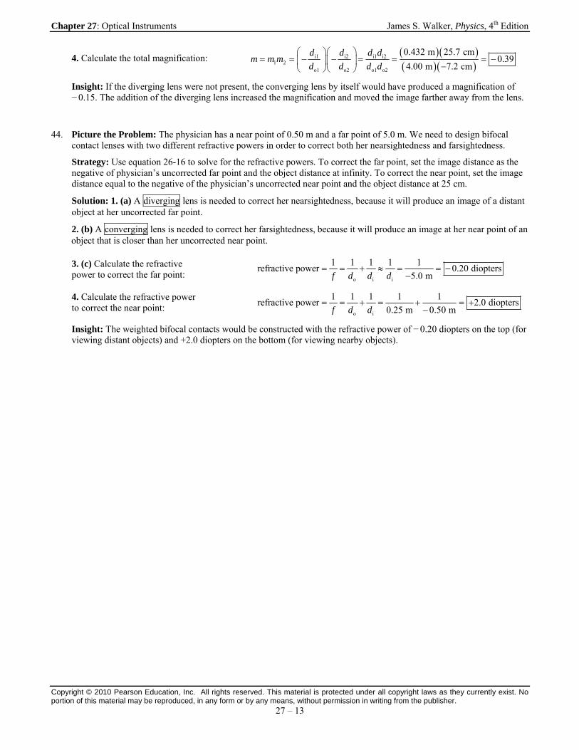
44. Picture the Problem: The physician has a near point of 0.50 m and a far point of 5.0 m. We need to design bifocal contact lenses with two different refractive powers in order to correct both her nearsightedness and farsightedness.
Strategy: Use equation 26-16 to solve for the refractive powers. To correct the far point, set the image distance as the negative of physician’s uncorrected far point and the object distance at infinity. To correct the near point, set the image distance equal to the negative of the physician’s uncorrected near point and the object distance at 25 cm.
Solution: 1. (a) A diverging lens is needed to correct her nearsightedness, because it will produce an image of a distant object at her uncorrected far point.
2. (b) A converging lens is needed to correct her farsightedness, because it will produce an image at her near point of an object that is closer than her uncorrected near point.
3. (c) Calculate the refractive power to correct the far point:
o i i
1 1 1 1 1refractive power 0.20 diopters
5.0 mf d d d
4. Calculate the refractive power to correct the near point:
o i
1 1 1 1 1refractive power 2.0 diopters
0.25 m 0.50 mf d d
Insight: The weighted bifocal contacts would be constructed with the refractive power of − 0.20 diopters on the top (for viewing distant objects) and +2.0 diopters on the bottom (for viewing nearby objects).

Chapter 27: Optical Instruments James S. Walker, Physics, 4th Edition
Copyright © 2010 Pearson Education, Inc. All rights reserved. This material is protected under all copyright laws as they currently exist. No portion of this material may be reproduced, in any form or by any means, without permission in writing from the publisher.
27 – 14
46. Picture the Problem: The refractive power of the distant-vision portion of a pair of bifocal glasses creates an image of distant objects at the wearer’s uncorrected far point. The refractive power of the close-vision portion of the bifocals creates an image of nearby objects at the wearer’s near point.
Strategy: The glasses will place the image of an infinitely distant object at the person’s far point. Find that image distance by setting the object distance to infinity and using a lens refractive power of – 0.0625 diopters. That distance is measured from the lens, so add 2.00 cm to find the uncorrected far point. The close-vision part of the bifocal places the image of an object that is 25.0 cm from the eye at the person’s uncorrected near point. To find the near point, first realize that the object distance for the lens is 23.0 cm because the glasses are 2.00 cm in front of the eye. Then solve equation 26-16 (using a lens refractive power of 1.05 diopters) for the image distance, which corresponds to the distance between the uncorrected near point and the glasses. We must add 2.00 cm to that result to find the distance between the uncorrected near point and the person’s eye.
Solution: 1. (a) Calculate the image distance for distant viewing:
1 111
io
1 1 1 10.0625 m 16.0 md
f d f
2. Add the eye-to-lens distance: ifar point = 0.0200 m 16.0 m 0.0200 m 16.0 md
3. (b) Calculate the image distance for near viewing:
1 1
io
1 1 11.05 diopters 30.3 cm
0.250 0.0200 md
f d
4. Add the eye-to-lens distance: inear point = 0.0200 m 30.3 cm 2.00 cm 32.3 cmd
Insight: Without the glasses, the person can only see clearly between 32.3 cm and 16.0 m. With the glasses, the person can see clearly for all distances greater than 25.0 cm.
Chapter 27: Optical Instruments James S. Walker, Physics, 4th Edition
Copyright © 2010 Pearson Education, Inc. All rights reserved. This material is protected under all copyright laws as they currently exist. No portion of this material may be reproduced, in any form or by any means, without permission in writing from the publisher.
27 – 15
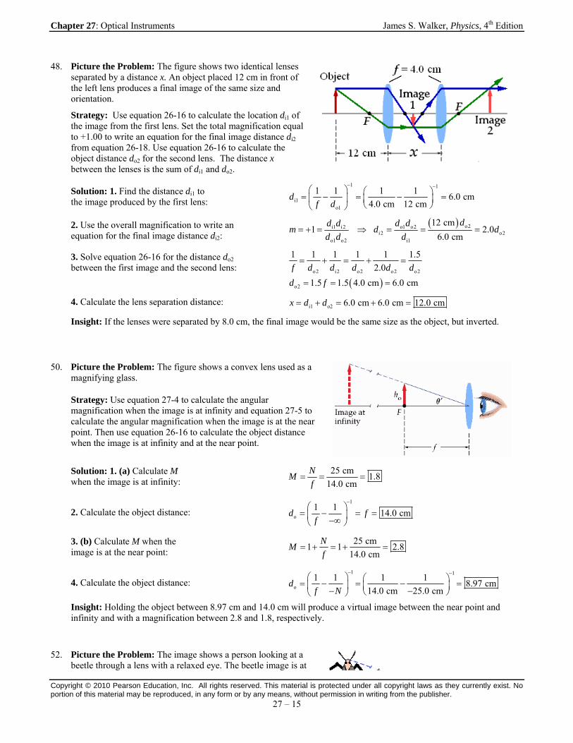
48. Picture the Problem: The figure shows two identical lenses separated by a distance x. An object placed 12 cm in front of the left lens produces a final image of the same size and orientation.
Strategy: Use equation 26-16 to calculate the location di1 of the image from the first lens. Set the total magnification equal to +1.00 to write an equation for the final image distance di2 from equation 26-18. Use equation 26-16 to calculate the object distance do2 for the second lens. The distance x between the lenses is the sum of di1 and do2.
Solution: 1. Find the distance di1 to the image produced by the first lens:
1 1
i1o1
1 1 1 16.0 cm
4.0 cm 12 cmd
f d
2. Use the overall magnification to write an equation for the final image distance di2:
o2o1 o2i1 i2i2 o2
o1 o2 i1
12 cm1 2.0
6.0 cm
dd dd dm d d
d d d
3. Solve equation 26-16 for the distance do2 between the first image and the second lens:
o2 i2 o2 o2 o2
o2
1 1 1 1 1 1.5
2.0
1.5 1.5 4.0 cm 6.0 cm
f d d d d d
d f
4. Calculate the lens separation distance: i1 o2 6.0 cm 6.0 cm 12.0 cmx d d
Insight: If the lenses were separated by 8.0 cm, the final image would be the same size as the object, but inverted.
50. Picture the Problem: The figure shows a convex lens used as a magnifying glass.
Strategy: Use equation 27-4 to calculate the angular magnification when the image is at infinity and equation 27-5 to calculate the angular magnification when the image is at the near point. Then use equation 26-16 to calculate the object distance when the image is at infinity and at the near point.
Solution: 1. (a) Calculate M when the image is at infinity:
25 cm1.8
14.0 cm
NM
f
2. Calculate the object distance:
1
o
1 114.0 cmd f
f
3. (b) Calculate M when the image is at the near point:
25 cm1 1 2.8
14.0 cm
NM
f
4. Calculate the object distance:
1 1
o
1 1 1 18.97 cm
14.0 cm 25.0 cmd
f N
Insight: Holding the object between 8.97 cm and 14.0 cm will produce a virtual image between the near point and infinity and with a magnification between 2.8 and 1.8, respectively.
52. Picture the Problem: The image shows a person looking at a beetle through a lens with a relaxed eye. The beetle image is at

Chapter 27: Optical Instruments James S. Walker, Physics, 4th Edition
Copyright © 2010 Pearson Education, Inc. All rights reserved. This material is protected under all copyright laws as they currently exist. No portion of this material may be reproduced, in any form or by any means, without permission in writing from the publisher.
27 – 16
infinity.
Strategy: Set the apparent length of the beetle equal to the actual length times the angular magnification (given by equation 27-4).
Solution: 1. Calculate the angular magnification:
25.0 cm2.48
10.1 cm
NM
f
2. Multiply the magnification by the length:
apparent length actual length 2.48 4.73 mm 11.7 mmM
Insight: If the lens were placed at 7.19 cm from the beetle, the image would appear 25.0 cm behind the lens (and at the average person’s near point) and the magnification would increase to 3.48, making the apparent length 16.4 mm.
54. Picture the Problem: When a diamond is placed at the focal point of a magnifying glass, a magnified image will be created at infinity.
Strategy: Use equation 27-4 to calculate the angular magnification.
Solution: Calculate the angular magnification:
20.8 cm2.77
7.50 cm
NM
f
Insight: If the diamond is moved closer to the lens, the image will move toward the jeweler’s near point, where the magnification will increase to 3.77.
56. Picture the Problem: A person with a near-point distance of 25 cm finds that a magnifying glass gives an angular magnification that is 1.5 times larger when the image is at the near point than when the image is at infinity.
Strategy: Set the magnification given equation 27-5 equal to 1.5 times the magnification given by equation 27-5 and solve for the focal length.
Solution: 1. Write the magnifications in terms of equations 27-4 and 27-5: np 1.5 1 1.5
N NM M
f f
2. Solve for the focal length: 1 1.5 0.5 0.5 0.5 25 cm 13 cm
N N Nf N
f f f
Insight: In order for np 2M M (with the same near point distance), the focal length would have to be equal to the
near point distance.
58. Picture the Problem: The figure shows a compound microscope with a fobjective = 2.2-cm objective lens and feyepiece = 5.4-cm eyepiece. The objective image is located di = 12 cm from the objective lens.
Strategy: Use equation 27-6 to calculate the total magnification. Set the near point equal to 25 cm.
Solution: Calculate the total magnification:
itotal
obj e
12 cm 25 cm
2.2 cm 5.4 cm
25
d NM
f f
Insight: To produce the image at 12 cm the object to be observed must be located at 2.7 cm below the objective lens.

Chapter 27: Optical Instruments James S. Walker, Physics, 4th Edition
Copyright © 2010 Pearson Education, Inc. All rights reserved. This material is protected under all copyright laws as they currently exist. No portion of this material may be reproduced, in any form or by any means, without permission in writing from the publisher.
27 – 17
60. Picture the Problem: An objective lens with focal length of 4.00 mm will produce a magnification of − 40.0 when used as a magnifying glass. Adding an eyepiece lens to this objective lens will produce a microscope with a total magnification of 125×.
Strategy: Use equation 26-18 to write image distance for the objective lens in terms of the lateral magnification and the object distance. Insert the resulting expression into equation 26-16 and solve for the object distance. Finally, solve equation 27-6 for the focal length of the eyepiece.
Solution: 1. (a) Write the image distance in terms of the magnification:
i o
i o
m d d
d md
2. Solve equation 26-16 for the object distance:
obj o i o o o
o obj
1 1 1 1 1 1 11
1 11 4.00 mm 1 4.10 mm
40.0
f d d d md d m
d fm
3. (b) Use equation 27-6 to write the total magnification: total o e oe
NM m M m
f
4. Solve for the eyepiece focal length:
oe
total
40.0 25 cm8.0 cm
125
m Nf
M
Insight: To double the magnification, without changing the objective lens, would require an eyepiece with a focal length of − 4.0 cm.
Chapter 27: Optical Instruments James S. Walker, Physics, 4th Edition
Copyright © 2010 Pearson Education, Inc. All rights reserved. This material is protected under all copyright laws as they currently exist. No portion of this material may be reproduced, in any form or by any means, without permission in writing from the publisher.
27 – 18
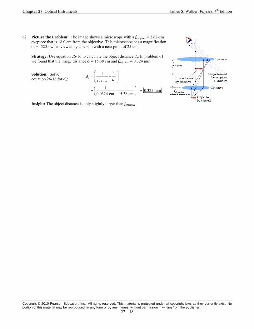
62. Picture the Problem: The image shows a microscope with a feyepiece = 2.62-cm eyepiece that is 18.0 cm from the objective. This microscope has a magnification of − 4525× when viewed by a person with a near point of 25 cm.
Strategy: Use equation 26-16 to calculate the object distance do. In problem 61 we found that the image distance di = 15.38 cm and fobjective = 0.324 mm.
Solution: Solve equation 26-16 for do:
1
oobjective i
1
1 1
1 10.325 mm
0.0324 cm 15.38 cm
df d
Insight: The object distance is only slightly larger than fobjective.

Chapter 27: Optical Instruments James S. Walker, Physics, 4th Edition
Copyright © 2010 Pearson Education, Inc. All rights reserved. This material is protected under all copyright laws as they currently exist. No portion of this material may be reproduced, in any form or by any means, without permission in writing from the publisher.
27 – 19
64. Picture the Problem: The figure shows a microscope with a feyepiece = 2.0-cm eyepiece and fobjective = 7.5-cm objective. The specimen is placed do = 122 mm from the objective lens.
Strategy: Use equation 26-16 to calculate the image distance from the objective lens. Add this distance to the focal length of the eyepiece to calculate the barrel length of the microscope. Solve equation 27-6 for the total magnification.
Solution: 1. (a) Calculate the image distance from the objective lens:
1
iobjective o
1
1 1
1 10.19 m
75 mm 122 mm
df d
2. Add the image distance to the eyepiece focal length: i eyepiece 0.19 0.020 m 0.21 mL d f
3. Calculate the total magnifi- cation from equation 27-6:
itotal
objective eyepiece
19 cm 25.0 cm32
7.5 cm 2.0 cm
d NM
f f
Insight: Replacing the 75-mm objective lens with a 50-mm lens (while keeping the same barrel length) would increase the magnification to – 48×. In such a case the object distance would decrease to 68 mm.
66. Picture the Problem: Two telescopes of different length produce the same angular magnification.
Strategy: Recall the principles involved in the construction of telescopes to answer the conceptual question.
Solution: The length of a telescope is equal to the sum of the focal lengths of its objective and eyepiece. On the other hand, the angular magnification is the ratio of the focal length of the objective to that of the eyepiece. Now, if the angular magnification is the same, and the overall length is greater, it follows that both the objective and eyepiece have greater focal lengths in the long telescope.
Insight: For instance, the shorter telescope of 10× angular magnification might have fobjective = 30 cm and feyepiece = 3.0 cm, whereas the longer telescope might have fobjective = 50 cm and feyepiece = 5.0 cm.
Chapter 27: Optical Instruments James S. Walker, Physics, 4th Edition
Copyright © 2010 Pearson Education, Inc. All rights reserved. This material is protected under all copyright laws as they currently exist. No portion of this material may be reproduced, in any form or by any means, without permission in writing from the publisher.
27 – 20
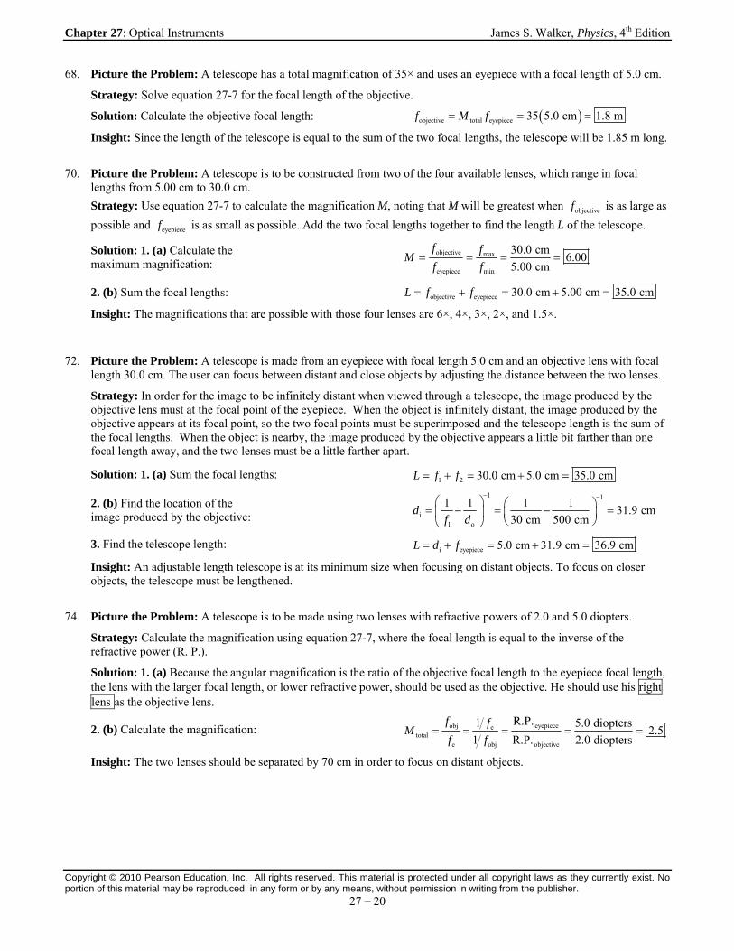
68. Picture the Problem: A telescope has a total magnification of 35× and uses an eyepiece with a focal length of 5.0 cm.
Strategy: Solve equation 27-7 for the focal length of the objective.
Solution: Calculate the objective focal length: objective total eyepiece 35 5.0 cm 1.8 mf M f
Insight: Since the length of the telescope is equal to the sum of the two focal lengths, the telescope will be 1.85 m long.
70. Picture the Problem: A telescope is to be constructed from two of the four available lenses, which range in focal lengths from 5.00 cm to 30.0 cm.
Strategy: Use equation 27-7 to calculate the magnification M, noting that M will be greatest when objectivef is as large as
possible and eyepiecef is as small as possible. Add the two focal lengths together to find the length L of the telescope.
Solution: 1. (a) Calculate the maximum magnification:
objective max
eyepiece min
30.0 cm6.00
5.00 cm
f fM
f f
2. (b) Sum the focal lengths: objective eyepiece 30.0 cm 5.00 cm 35.0 cmL f f
Insight: The magnifications that are possible with those four lenses are 6×, 4×, 3×, 2×, and 1.5×.
72. Picture the Problem: A telescope is made from an eyepiece with focal length 5.0 cm and an objective lens with focal length 30.0 cm. The user can focus between distant and close objects by adjusting the distance between the two lenses.
Strategy: In order for the image to be infinitely distant when viewed through a telescope, the image produced by the objective lens must at the focal point of the eyepiece. When the object is infinitely distant, the image produced by the objective appears at its focal point, so the two focal points must be superimposed and the telescope length is the sum of the focal lengths. When the object is nearby, the image produced by the objective appears a little bit farther than one focal length away, and the two lenses must be a little farther apart.
Solution: 1. (a) Sum the focal lengths: 1 2 30.0 cm 5.0 cm 35.0 cmL f f
2. (b) Find the location of the image produced by the objective:
1 1
i1 o
1 1 1 131.9 cm
30 cm 500 cmd
f d
3. Find the telescope length: i eyepiece 5.0 cm 31.9 cm 36.9 cmL d f
Insight: An adjustable length telescope is at its minimum size when focusing on distant objects. To focus on closer objects, the telescope must be lengthened.
74. Picture the Problem: A telescope is to be made using two lenses with refractive powers of 2.0 and 5.0 diopters.
Strategy: Calculate the magnification using equation 27-7, where the focal length is equal to the inverse of the refractive power (R. P.).
Solution: 1. (a) Because the angular magnification is the ratio of the objective focal length to the eyepiece focal length, the lens with the larger focal length, or lower refractive power, should be used as the objective. He should use his right lens as the objective lens.
2. (b) Calculate the magnification: eyepieceobj e
totale obj objective
R.P.1 5.0 diopters2.5
1 R.P. 2.0 diopters
f fM
f f
Insight: The two lenses should be separated by 70 cm in order to focus on distant objects.

Chapter 27: Optical Instruments James S. Walker, Physics, 4th Edition
Copyright © 2010 Pearson Education, Inc. All rights reserved. This material is protected under all copyright laws as they currently exist. No portion of this material may be reproduced, in any form or by any means, without permission in writing from the publisher.
27 – 21
Chapter 27: Optical Instruments James S. Walker, Physics, 4th Edition
Copyright © 2010 Pearson Education, Inc. All rights reserved. This material is protected under all copyright laws as they currently exist. No portion of this material may be reproduced, in any form or by any means, without permission in writing from the publisher.
27 – 22
76. Picture the Problem: A standard telescope produces a magnified image of the Moon.
Strategy: Use equation 27-7 to calculate the angular magnification of the telescope. Multiply the angular size of the moon (0.50) by the magnification of the telescope to determine the angular size of the Moon’s image.
Solution: 1. Calculate the angular magnification: objective
totaleyepiece
53 cm21.2
2.5 cm
fM
f
2. Multiply the angular size by the magnification: 21.2 0.50 11M
Insight: The increased magnification enables the observer to distinguish mountains and craters on the Moon’s surface.
78. Picture the Problem: A telescope with total length of 275 mm has an objective focal length of 257 mm.
Strategy: Subtract the objective focal length from the total length to calculate the focal length of the eyepiece. Then use equation 27-7 to calculate the angular magnification.
Solution: 1. (a) Calculate the focal length of the eyepiece: eyepiece objective 275 mm 257 mm 18 mmf L f
2. (b) Use equation 27-7 to calculate the magnification: objective
totaleyepiece
257 mm14
18 mm
fM
f
Insight: To obtain a magnification of 20× with the same telescope length, the objective focal length would need to be increased to 262 mm.

Chapter 27: Optical Instruments James S. Walker, Physics, 4th Edition
Copyright © 2010 Pearson Education, Inc. All rights reserved. This material is protected under all copyright laws as they currently exist. No portion of this material may be reproduced, in any form or by any means, without permission in writing from the publisher.
27 – 23
80. Picture the Problem: The lens from a human eye, normally surrounded with aqueous humor on one side and vitreous humor on the other side, is removed from an eye and surrounded by air.
Strategy: Consider the effect of the surrounding medium on the refraction that occurs at the lens surface.
Solution: When the lens is in air the difference in index of refraction between the lens and its surroundings is greater than when it is surrounded by the aqueous and vitreous humors. It follows that the lens bends rays of light more in air; hence, its refractive power will be greater than 15 diopters when surrounded by air.
Insight: In a similar way, when you open your eyes underwater without goggles you are unable to focus on anything, because the refraction that occurs at the cornea surface is reduced and the refractive power of your eye is less than it should be for adequate focusing.
82. Picture the Problem: An optical system consists of two lenses, one with a focal length of 50 cm and the other with a focal length of 2.5 cm. The separation between the lenses is 52.5 cm.
Strategy: Recall the principles of the construction of microscopes and telescopes when answering the question.
Solution: If a telescope were constructed from these lenses, the separation between the lenses would equal the sum of the focal lengths, or 52.5 cm. This matches the given separation, so we conclude that the instrument is a telescope.
Insight: The magnifying power of this telescope would be o e 50 cm 2.5 cm 20 .f f If a microscope were
constructed from these lenses with a “barrel length” of 16 cm, the shorter focal length would be the objective and the
magnifying power would be
itotal
objective eyepiece
16 cm 25 cm3.2 .
2.5 cm 50 cm
d NM
f f The lenses make a better telescope
than microscope!

Chapter 27: Optical Instruments James S. Walker, Physics, 4th Edition
Copyright © 2010 Pearson Education, Inc. All rights reserved. This material is protected under all copyright laws as they currently exist. No portion of this material may be reproduced, in any form or by any means, without permission in writing from the publisher.
27 – 24
84. Picture the Problem: A patient has a maximum refractive power of 44.1 diopters. The refractive power of the eye is at a maximum when viewing close objects.
Strategy: Solve equation 26-16 for the patient’s near point, where the image distance is the distance from lens to retina (2.4 cm) and the focal length is the inverse of the refractive power.
Solution: 1. (a): When an eye is focused on the near point of a normal, healthy eye (at 25 cm), equation 26-16 gives its
refractive power as near normal i
1 1 1 1 145.7 diopters.
0.25 m 0.0240 mf N d A person whose eyes cannot refract this
strongly cannot clearly see objects as close as 25 cm. The patient is farsighted.
2. (b) Solve equation 26-16 for the patient’s near point:
1 11
near i
1 1 144.1 m 41.1 cm
0.0240 mN
f d
Insight: Contact lenses with a refractive power of 45.7 − 44.1 = +1.6 diopters will correct the patient’s farsightedness.
86. Picture the Problem: Galileo’s telescope consists of a converging objective lens and a diverging eyepiece. The focal length of the object is four times that of the eyepiece.
Strategy: The image of distant objects formed by the objective lens will be at the focal point of the lens. Sketch the objective image at the focal point. Then sketch a parallel ray approaching the image from the objective lens. This ray will deflect away from the principal axis as if it came from the eyepiece focal point on the left side of the lens. Extrapolate this line back through the focal point. Then sketch the ray through the center of the eyepiece. Draw the final image where the two rays intersect.
Solution: Sketch the parallel and center ray traces:
Insight: The resulting final image is virtual, upright, and magnified.
88. Picture the Problem: Two lenses of focal lengths f1 = 2.60 cm and f2 = 20.4 cm are to be used to make either a telescope or a microscope.
Strategy: Use equation 27-7 to calculate the magnification when the lenses are configured as a telescope. To calculate the magnification when configured as a microscope, use equation 26-16 to find the image distance from the objective lens. Then use equation 27-6 to calculate the magnification.
Solution: 1. (a) Since objective
totaleyepiece
fM
f and 2 1,f f arrange the lenses as a telescope with objective 2f f and eyepiece 1 .f f
2. (b) Calculate the magnification: objective 2
totaleyepiece 1
20.4 cm7.85
2.60 cm
f fM
f f
3. (c) Arrange the lenses as a microscope with objective 1f f and eyepiece 2f f .
4. (d) Solve equation 26-16 for id :
1 1
iobjective o
1 1 1 125 cm
2.60 cm 2.90 cmd
f d
Chapter 27: Optical Instruments James S. Walker, Physics, 4th Edition
Copyright © 2010 Pearson Education, Inc. All rights reserved. This material is protected under all copyright laws as they currently exist. No portion of this material may be reproduced, in any form or by any means, without permission in writing from the publisher.
27 – 25
5. Insert the image distance into equation 27-6:
itotal
objective eyepiece
25 cm 25 cm12
2.60 cm 20.4 cm
d NM
f f
Insight: As a telescope these two lenses should be separated by 23.0 cm, but as a microscope they would be separated by eyepiece i 2.60 25 cm 28 cm.f d
Chapter 27: Optical Instruments James S. Walker, Physics, 4th Edition
Copyright © 2010 Pearson Education, Inc. All rights reserved. This material is protected under all copyright laws as they currently exist. No portion of this material may be reproduced, in any form or by any means, without permission in writing from the publisher.
27 – 26
90. Picture the Problem: The figure shows a light (object) reflecting off the front of the cornea. Because the cornea is convex the light produces a reduced, virtual image.
Strategy: Use equation 26-8 to calculate the image distance.Then use equation 26-6 to calculate the focal length of the cornea and equation 26-3 to calculate the radius of curvature.
Solution: 1. Solve for the image distance: i o 0.035 10.0 cm 0.35 cmd md
2. Use equation 26-6 to calculate f :
1 1
o i
1 1 1 10.363 cm
10.0 cm 0.35 cmf
d d
3. Calculate the radius of curvature: 2 2 0.363 cm 7.3 mmR f
Insight: Note that the radius of curvature of the cornea (7.3 mm) is much less than the radius of curvature of the eyeball (1.25 cm).
92. Picture the Problem: A person is able to focus on distant objects with the aid of glasses that have a refractive power of −1.35 diopters.
Strategy: Use equation 26-16 to calculate the location of the image that is produced by the glasses of refractive power −1.35 diopters when viewing distant objects (do = ). That distance corresponds to the person’s far point.
Solution: 1. (a) A lens with a refractive power of –1.35 diopters is a diverging lens. Because diverging lenses are used to help view distant objects, the person is nearsighted.
2. (b) Calculate the image distance:
1 1
io
1 1 1 1
1 10.741 m
refractive power 1.35 diopters
df d f
f
The person’s far point is 74.1 cm .
Insight: We solved for the distance from the glasses at which the image of a distant object would appear. If the person wears the glasses 2.0 cm from her eye, her unaided far point is really 76.1 cm. If the person’s unaided near point is 25.0 cm and she wears her glasses 2.0 cm from her eye, her near point becomes
11
oi
1 1 11.35 diopters 33 cm 33 2.0 cm 35 cm
25 2.0 cmd N
f d
when wearing the glasses.
94. Picture the Problem: A Galilean telescope is constructed with an objective lens of focal length 75.6 cm and an eyepiece with focal length −18.0 mm.
Strategy: Set the distance between the two lenses equal to the sum of the focal lengths. Use equation 27-7 to calculate the angular magnification.
Solution: 1. (a) Sum the focal lengths: objective eyepiece 75.6 cm 1.80 cm 73.8 cmL f f
2. (b) Calculate the angular magnification: objective
totaleyepiece
75.6 cm42.0
1.80 cm
fM
f
Chapter 27: Optical Instruments James S. Walker, Physics, 4th Edition
Copyright © 2010 Pearson Education, Inc. All rights reserved. This material is protected under all copyright laws as they currently exist. No portion of this material may be reproduced, in any form or by any means, without permission in writing from the publisher.
27 – 27
Insight: In the Galilean telescope the image is not inverted, as it is in a refracting telescope with two convex lenses.

Chapter 27: Optical Instruments James S. Walker, Physics, 4th Edition
Copyright © 2010 Pearson Education, Inc. All rights reserved. This material is protected under all copyright laws as they currently exist. No portion of this material may be reproduced, in any form or by any means, without permission in writing from the publisher.
27 – 28
96. Picture the Problem: The figure shows a farsighted person wearing glasses with refractive power 3.6 diopters. The glasses create an image at the person’s near point of an object that is 25.0 cm from the person’s eye (the corrected near point).
Strategy: Solve equation 26-16 for the image distance, where the inverse of the focal length is the refractive power (R.P.) of the lens and the object distance is the distance between the lens and the corrected near point. Add the eye-to-lens distance D = 2.5 cm to the absolute value of the image distance to find the uncorrected near point.
Solution: 1. Calculate the image distance:
1 1
io o
1
1 1 1R.P.
13.6 diopters 1.18 m
0.25 m 0.025 m
df d d
2. Calculate the near point: 1.18 m 0.025 m 1.21 mN
Insight: This person could alternatively use
o i
1 1 1 1R.P. 3.2 diopter
0.25 m 1.18 md d
contact lenses.
98. Picture the Problem: The amount of light incident on a photographic plate is proportional to the time length of exposure. The diameter of the camera aperture also limits the light entering the lens.
Strategy: For a given exposure time, the amount of light that falls on the film is proportional to the area of the aperture. Set the film exposure to be proportional to the area of the aperture and write the area in terms of the aperture setting.
Solution: Write the image brightness in terms of the f-number.
22 2
2amount of light
4 4 -number 4 -number
D f fA
f f
Insight: It is necessary to either increase the time of exposure or increase the diameter of the telescope aperture in order
to observe faint stars and galaxies.

Chapter 27: Optical Instruments James S. Walker, Physics, 4th Edition
Copyright © 2010 Pearson Education, Inc. All rights reserved. This material is protected under all copyright laws as they currently exist. No portion of this material may be reproduced, in any form or by any means, without permission in writing from the publisher.
27 – 29
100. Picture the Problem: The figure shows an object 25.0 cm from a convex lens of focal length 20.0 cm. 10.0 cm behind the lens is a plane mirror. Light from a matchstick will pass through the lens, reflect off the plane mirror, and pass back through the lens before reaching the viewers eye.
Strategy: Use equation 26-16 to calculate the location of the image from the lens. Then determine the location of the virtual image produced by the mirror. Finally, use equation 26-16 to calculate the location of the final image produced as the light passes back through the lens. Multiply the magnifications from each time the light passes through the lens to calculate the total magnification.
Solution: 1. (a) Calculate the image distance from the lens:
1 1
io
1 1 1 1100 cm
20.0 cm 25.0 cmd
f d
2. The lens forms an image 100 cm – 10.0 cm = 90 cm behind the mirror. This image is reflected from the mirror so that it appears 90 cm in front of the mirror and 90 cm – 10.0 cm = 80 cm in front (to the left) of the lens. Because the light is now traveling from right to left, this is a virtual object and the object distance is − 80 cm.
3. Calculate the position of the final image:
1
i
1 116 cm to the left of the lens
20.0 cm 80.0 cmd
4. (b) Because light passes through the image, it is real .
5. (c) Calculate the total magnification:
i1 i2
1 2o1 o2
100 cm 16 cm0.80
25.0 cm 80 cm
d dm m m
d d
6. (d) Because 0.80 0, the image is inverted.
Insight: Another way of viewing this problem is to replace the mirror with the mirror image of the lens. The dotted line in the center represents the location of the mirror. Because the second lens is at the focal point of the first, the initial P ray becomes the M ray of the second lens. The initial M ray becomes the F ray. The initial F ray becomes the final P ray. The resulting diagram shows that the final image is real, inverted, and reduced.

Chapter 27: Optical Instruments James S. Walker, Physics, 4th Edition
Copyright © 2010 Pearson Education, Inc. All rights reserved. This material is protected under all copyright laws as they currently exist. No portion of this material may be reproduced, in any form or by any means, without permission in writing from the publisher.
27 – 30
102. Picture the Problem: An object is placed 50.0 cm in front of two lenses. The closest lens has a focal length of −20.0 cm, and the second has a focal length of 30.0 cm. The distance between the lenses can be varied.
Strategy: Use equation 26-16 to calculate the location of the image from the first lens. Then subtract this distance from the distance between the lenses (x) to calculate the object distance for the second lens. Use equation 26-16 to calculate the image distance from the second lens. Finally, multiply the magnification from each lens (from equation 26-18) together to get the total magnification.
Solution: 1. Calculate the image distance from the first lens:
1 1
i11 o1
1 1 1 114.3 cm
20.0 cm 50.0 cmd
f d
2. Find the object distance for the second lens: o2 14.3 cm 14.3 cmd x x
3. Calculate the second image distance:
1 1
i22 o2
1 1 1 1
30.0 cm 14.3 cmd
f d x
4. Calculate the magnification:
i2i1 i21 2
o1 o2
14.3 cm
50.0 cm 14.3 cm
dd dm m m
d d x
5. (a) Set x = 115 cm:
1
i2
1 139.1 cm
30.0 cm 115 cm 14.3 cm
14.28 cm 39.1 cm0.0863
50.0 cm 115 cm 14.3 cm
d
m
6. (b) Set x = 30.0 cm:
1
i2
1 193.0 cm
30.0 cm 30 cm 14.3 cm
14.3 cm 93.0 cm0.600
50.0 cm 30 cm 14.3 cm
d
m
7. (c) Set x = 0.0:
1
i2
1 127.3 cm
30.0 cm 0 14.3 cm
14.3 cm -27.3 cm0.545
50.0 cm 0 14.3 cm
d
m
8. (d) Calculate the effective focal length from the image and object distances:
1 1
effo i
1 1 1 160.0 cm
50.0 cm 27.3 cmf
d d
9. Calculate the effective focal length from the initial focal lengths:
1 1
eff1 2
1 1 1 160.0 cm
20.0 cm 30.0 cmf
f f
Insight: The final image is virtual when the lens separation is in the range 0 15.7 cm.x The image is real for all other lens separations.
Chapter 27: Optical Instruments James S. Walker, Physics, 4th Edition
Copyright © 2010 Pearson Education, Inc. All rights reserved. This material is protected under all copyright laws as they currently exist. No portion of this material may be reproduced, in any form or by any means, without permission in writing from the publisher.
27 – 31
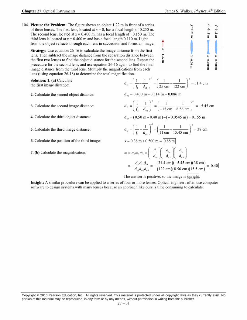
104. Picture the Problem: The figure shows an object 1.22 m in front of a series of three lenses. The first lens, located at x = 0, has a focal length of 0.250 m. The second lens, located at x = 0.400 m, has a focal length of −0.150 m. The third lens is located at x = 0.400 m and has a focal length 0.110 m. Light from the object refracts through each lens in succession and forms an image.
Strategy: Use equation 26-16 to calculate the image distance from the first lens. Then subtract the image distance from the separation distance between the first two lenses to find the object distance for the second lens. Repeat the procedure for the second lens, and use equation 26-16 again to find the final image distance from the third lens. Multiply the magnifications from each lens (using equation 26-18) to determine the total magnification.
Solution: 1. (a) Calculate the first image distance:
1 1
i11 o1
1 1 1 131.4 cm
25 cm 122 cmd
f d
2. Calculate the second object distance: o2 0.400 m 0.314 m 0.086 md
3. Calculate the second image distance:
1 1
i22 o2
1 1 1 15.45 cm
15 cm 8.56 cmd
f d
4. Calculate the third object distance: o3 0.50 m 0.40 m 0.0545 m 0.155 md
5. Calculate the third image distance:
1 1
i33 o3
1 1 1 138 cm
11 cm 15.45 cmd
f d
6. Calculate the position of the third image: 0.38 m 0.500 m 0.88 mx
7. (b) Calculate the magnification:
i3i1 i21 2 3
o1 o2 o3
i1 i2 i3
o1 o2 o3
31.4 cm 5.45 cm 38 cm0.40
122 cm 8.56 cm 15.5 cm
dd dm m m m
d d d
d d d
d d d
The answer is positive, so the image is upright.
Insight: A similar procedure can be applied to a series of four or more lenses. Optical engineers often use computer software to design systems with many lenses because an approach like ours is time consuming to calculate.

Chapter 27: Optical Instruments James S. Walker, Physics, 4th Edition
Copyright © 2010 Pearson Education, Inc. All rights reserved. This material is protected under all copyright laws as they currently exist. No portion of this material may be reproduced, in any form or by any means, without permission in writing from the publisher.
27 – 32
106. Picture the Problem: The image shows a person looking through a magnifier at an object located inside the observer’s near point. The image is formed at the near point, which corresponds to the maximum angular magnification.
Strategy: From Example 27-4, note that the magnification of a magnifying glass with the object at od is oM N d where N is
the viewer’s near point. Write the object distance in terms of the focal length and image distance using equation 26-16. Then note that the greatest magnification will occur when the image is as close to the eye as possible (with a clear image). This situation occurs when the image is at the near point.
Solution: 1. Replace the object distance in the magnification equation using equation 26-16:
o o i
1 1 1NM N N
d d f d
2. Set the virtual image distance equal to the near point: 1 1
N N N NM
f N f f
Insight: If the focal length f of the lens remains constant, this equation indicates that a larger maximum magnification is possible for a person with a larger near point distance N.
108. Picture the Problem: A patient receives a rigid intraocular lens (IOL) whose focus cannot be changed—it is designed to provide clear vision of objects at infinity. The patient will use corrective contacts to allow for close vision.
Strategy: Use equation 26-16 to find the refractive power that would produce an image at infinity for an object at 0.230 m.
Solution: Calculate the refractive power:
o i
1 1 1 1 14.35 diopters
0.230 mf d d
Insight: Reading glasses that are worn 2.00 cm from this person’s eyes would need refractive power of 4.76 diopters.
110. Picture the Problem: The figure shows a person wearing glasses with a focal length of −301 cm. The glasses sit D = 2.00 cm in front of the person’s eyes and allow the person to focus on objects that are at infinity.
Strategy: Solve equation 26-16 for the image distance when the object is at infinity. Add D to the absolute value of the image distance to determine the far point.
Solution: 1. (a) The far point is less than 323 cm. The smaller focal length brings the image closer to the eyes.
2. (b) Solve equation 26-16 for di:
1 1
io
1 1 1 1301 cmd f
f d f
3. Calculate the far point: iFar point = 2.00 cm 301 cm + 2.00 cm = 303 cmd
Insight: The refractive power of this person’s glasses is − 0.33 diopters.
112. Picture the Problem: The figure shows a person wearing glasses with a refractive power of 2.75 diopters. The glasses are D = 2.00 cm in front of her eyes and create a virtual image at her near point of an object that is 25.0 cm from her eye.
Chapter 27: Optical Instruments James S. Walker, Physics, 4th Edition
Copyright © 2010 Pearson Education, Inc. All rights reserved. This material is protected under all copyright laws as they currently exist. No portion of this material may be reproduced, in any form or by any means, without permission in writing from the publisher.
27 – 33
Strategy: Calculate the object distance from the lens by subtracting the lens-to-eye distance from the object location. Then use equation 26-16 to calculate the image distance. Add D to the absolute value of the image distance to determine the near point.
Solution: 1. (a) Because the refractive power of these lenses is greater than the refractive power of Example 27-3, the near point is greater than 57.0 cm.
2. (b) Calculate the object distance: o 25.0 cm 2.00 cm 23.0 cmd
3. Solve equation 26-16 for di:
1 1
io
1 1 12.75 diopters 62.6 cm
0.230 md
f d
4. Add the eye-to-lens distance: Near point = 62.6 cm + 2.00 cm = 64.6 cm
Insight: If this person wore contact lenses instead of glasses, the required refractive power would be 2.45 diopters.


![Ep118 Lec08 Optical Instruments[1]](https://static.fdocuments.net/doc/165x107/563db822550346aa9a90dea0/ep118-lec08-optical-instruments1.jpg)
