CHAPTER 25 Advanced Solids, Faces, and Edges€¦ · 2 25.1 INTRODUCTION TO ADVANCED SOLIDS, FACES,...
20
1 CHAPTER 25 Advanced Solids, Faces, and Edges Learning Objectives In this chapter, we continue to introduce additional advanced tools, including Polysolid Helix 3D path array 3Dalign Faces Move Offset Delete Rotate Copy Color Edges By the end of this chapter, you will have the complete 3D object design tool set in your hands. Estimated time for completion of this chapter: 2 hours.
Transcript of CHAPTER 25 Advanced Solids, Faces, and Edges€¦ · 2 25.1 INTRODUCTION TO ADVANCED SOLIDS, FACES,...

1
CHAPTER 25 Advanced Solids, Faces, and Edges
Learning Objectives In this chapter, we continue to introduce additional advanced tools, including Polysolid Helix 3D path array 3Dalign Faces Move Offset Delete Rotate Copy Color Edges
By the end of this chapter, you will have the complete 3D object design tool set in your hands. Estimated time for completion of this chapter: 2 hours.

2
25.1 INTRODUCTION TO ADVANCED SOLIDS, FACES, AND EDGES With this chapter, we continue to introduce advanced 3D tools. While they are not the primary tools you use in day-to-day 3D work, they are still needed to round out your knowledge. Specifically, we add polysolid, helix, 3D path array, and 3Dalign to the list and focus on working with faces (move, offset, delete, rotate, copy, and color) as well as edges (copy and color). Polysolid After trying out polysolid, you may never create a wall via the extrude command again. A polysolid is analogous to a polyline. What you get is continuous sections of extruded rectangles similar to continuous sections of a pline in 2D. It is a great tool for quickly constructing 3D walls of a building. Once you begin creating the polysolid, you can continue to “stitch” forward one section at a time by just pointing the mouse in the direction you want to go and entering a distance (usually with Ortho on).
Step 1. Start polysolid via any of the preceding methods.
AutoCAD says: _Polysolid Height = 4.0000, Width = 0.2500, Justification = Center Specify start point or [Object/Height/Width/Justify] <Object>:
Step 2. These are the default values for the height and width, and they are OK for now. Go into the SW Isometric view and activate Ortho. Then, click anywhere on the screen. AutoCAD says: Specify next point or [Arc/Undo]:
Step 3. A connected polysolid is drawn every time you click, so do several clicks and press Enter when done, then shade and color the polysolid. You should have something similar to what is shown in Figure 25.1 on your screen.
FIGURE 25.1 Basic polysolid.
To create a section of a wall similar to what you did in Chapter 24, you need to change the height and width of the polysolid by selecting h for height or w for width in the suboptions.
For height, AutoCAD says: Specify height <4.0000>: Enter 72 for the height.
For width,
AutoCAD says: Specify width <0.2500>: Enter 5 for the width.
Polysolid has two more useful features. The first occurs if you select the Arc suboption while clicking around; you can create an arc section, as seen in Figure 25.2.
3
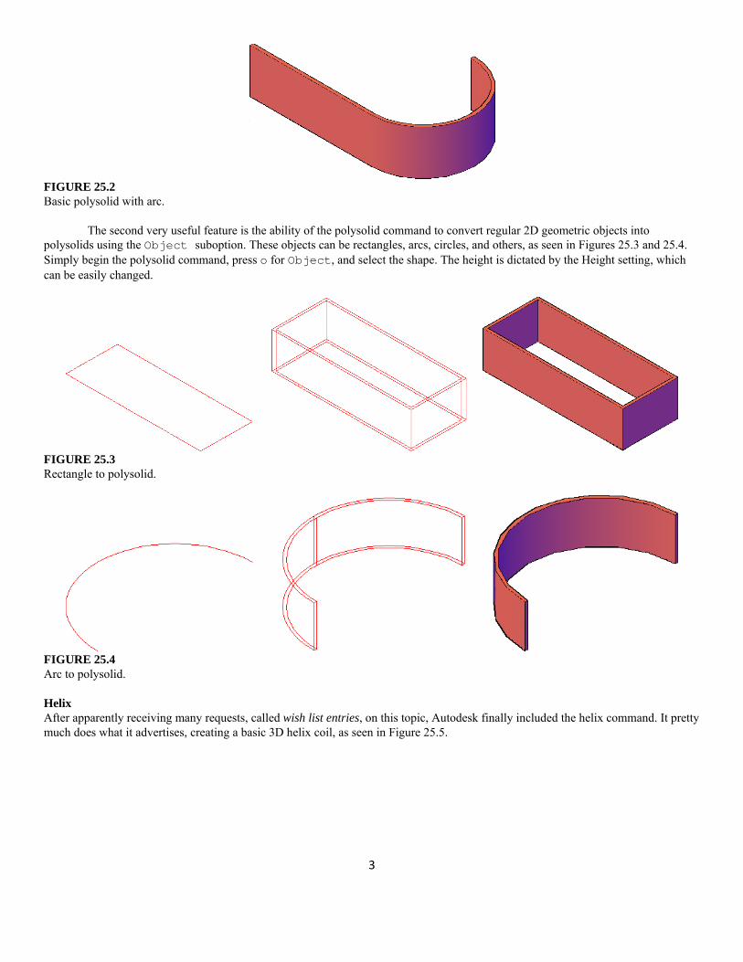
FIGURE 25.2 Basic polysolid with arc.
The second very useful feature is the ability of the polysolid command to convert regular 2D geometric objects into
polysolids using the Object suboption. These objects can be rectangles, arcs, circles, and others, as seen in Figures 25.3 and 25.4. Simply begin the polysolid command, press o for Object, and select the shape. The height is dictated by the Height setting, which can be easily changed.
FIGURE 25.3 Rectangle to polysolid.
FIGURE 25.4 Arc to polysolid. Helix After apparently receiving many requests, called wish list entries, on this topic, Autodesk finally included the helix command. It pretty much does what it advertises, creating a basic 3D helix coil, as seen in Figure 25.5.

4
FIGURE 25.5 Basic helix coil.
Step 1. Start helix via any of the preceding methods.
AutoCAD says: Number of turns = 3.0000 Twist = CCW Specify center point of base:
Step 2. You are asked here to specify where you want the helix coil to be. Generally, you click on any random point to just create the helix. Afterward, you can move it into a specific position according to design needs. AutoCAD says: Specify base radius or [Diameter] <1.0000>:
Step 3. This is the overall radius or diameter of the bottom part of the coil. Enter any value; 10 is used in this example. AutoCAD says: Specify top radius or [Diameter] <10.0000>:
Step 4. The top radius or diameter of the coil does not necessarily have to be the same as the bottom; this way your coil can taper in or expand if needed. For this example, however, we choose the top and bottom to be the same size (10). AutoCAD says: Specify helix height or [Axis endpoint/Turns/turn Height/tWist]
<1.0000>: Step 5. Although you can manually pull the helix into shape at this point, a better approach is to indicate the number of turns and
helix height. Type in t for Turns and press Enter. AutoCAD says: Enter number of turns <3.0000>:
Step 6. Enter any reasonable value; 10 is used for this example. AutoCAD says: Specify helix height or [Axis endpoint/Turns/turn Height/tWist]
<1.0000>: Step 7. Now type in the height you wish the helix to have; 40 is used in this example.
The final result is seen on the left-hand side of Figure 25.6. Now, how would you give the helix a thickness, like a real spring? We recently covered the answer to that: the sweep command. Create a small circle profile positioned near the helix. Using the helix as a path, create a sweep of the circle profile, as seen in the rest of Figure 25.6.
While this is an easy way to model the coil as presented in the challenge drawing of the previous chapter, resist the temptation to do so and search for other ways.

5
FIGURE 25.6 Completed helix coil with sweep. 3D Path Array The array command was first introduced in Chapter 8. Having gone through a bit of a redesign, array is now Ribbon or command-line driven (no more dialog boxes) and features a new, third variation, the path array. This allows you to select an object and a path. Multiple instances of that object are then created along the path. The same exact thing can be done in 3D. To try this out, we create a spiral staircase. Draw a small step consisting of a 20″×8″ rectangle extruded to a thickness of 1″, as seen in Figure 25.7. Do not forget to add color and shade.
FIGURE 25.7 20" ×8" ×1" step for path array.
Then, using your new helix skills, create a helix of any reasonable size. The one used in this example is 15 ×15, with a height
of 50. The step is rotated 90° to align with the bottom of the helix, as seen in Figure 25.8.
FIGURE 25.8 Helix for path array.
Finally, run through the path array command (it is the same for 3D as for 2D). Just as a reminder, you are asked to select the
object and indicate this is a path array. Then, type in 50 when asked how many objects. Finally, press Enter twice to complete the 3D path array command. Your results should look similar to Figure 25.9, which shows the new staircase from two views. Note that the path is still visible but can be erased if desired, of course.

6
FIGURE 25.9 Completed spiral staircase (two views).
While this was just a “quick and dirty” example, you can easily see how some time spent crafting a proper set of stairs,
handrails, and a frame yields a graceful and impressive design of a spiral staircase with comparatively modest effort. You will try this out in one of the end-of-chapter exercises. 3Dalign As you may recall from Level 2, aligning objects in 2D can be somewhat tricky, and the align command is quite useful in quickly and easily mating up geometric pieces. In 3D, aligning objects can be even more of a challenge, especially if they are out of alignment in all three axes. Therefore, 3Dalign is almost mandatory to accomplish this. Go ahead, create and position the two blocks as described next.
In Figure 25.10, on the left (Block 1) is a 25″×15″ block, extruded to 15″. It is even with the X, Y, and Z axes, as seen in the standard SW Isometric view, while a similar, copied Block 2 on the right has been rotated 15° along the X and Y axes and 30° along the Z axis. We need to align Face 1 with Face 2 by moving Block 2 (since it is the rotated one) and bringing it around to have its face match up with the face of the correctly aligned Block 1.
FIGURE 25.10 Blocks for 3Dalign.

7
Step 1. Start the 3Dalign command via any of the preceding methods. AutoCAD says: Select objects:
Step 2. Select just the misaligned Block 2 (you could, in theory, pick Block 1 as well) and press Enter. AutoCAD says: Specify source plane and orientation …Specify base point or [Copy]:
Step 3. Here, you need to click on and choose three consecutive source points on Block 2’s face that you want used as points of attachment to Block 1. Several combinations are possible, so let us arbitrarily choose the points shown in Figure 26.11. As you select these three points, AutoCAD says: Specify second point or [Continue] <C>: Specify third point or
[Continue] <C>: Specify destination plane and orientation …Specify first destination point:
Step 4. Now, you are ready to specify the destination points. Here you have to be careful and think about what those points actually are, as random choices produce random results. Observe that, in this example, Block 2 needs to be rotated 180° for its lighter face to match up to Block 1’s lighter face. Therefore, the destination points need to be mirror images of the source points, not the exact same ones.
FIGURE 25.11 Selecting points, Step 3.
FIGURE 25.12 Selecting points, Step 4.
The order we picked the source points was Top Left→Top Right→Bottom Right. As we swing Block 2 around, the corresponding points on Block 1 are Top Right→Top Left→Bottom Left. Do you see why? Visualize this on a nearby object, one that you can pick up, locate the points on, and turn around: perhaps a cell phone or a book. Let us now select those points, as seen in Figure 25.12. As you are doing this, AutoCAD says: Specify first destination point: Specify second destination point or
[eXit]<X>: Specify third destination point or [eXit]<X>: Step 5. Select the points carefully; Block 2 may be in the way, so you need to trust your OSNAPs (or just stay in wireframe mode to
see the points). The final result is shown in Figure 25.13.
8
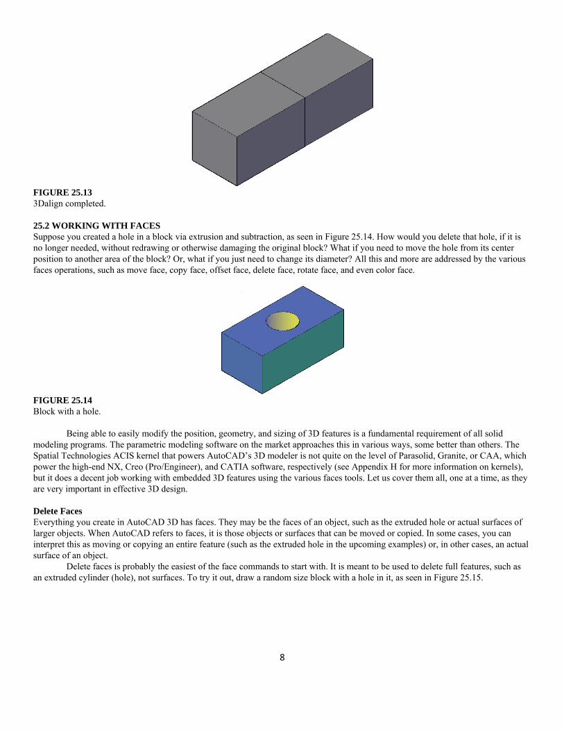
FIGURE 25.13 3Dalign completed. 25.2 WORKING WITH FACES Suppose you created a hole in a block via extrusion and subtraction, as seen in Figure 25.14. How would you delete that hole, if it is no longer needed, without redrawing or otherwise damaging the original block? What if you need to move the hole from its center position to another area of the block? Or, what if you just need to change its diameter? All this and more are addressed by the various faces operations, such as move face, copy face, offset face, delete face, rotate face, and even color face.
FIGURE 25.14 Block with a hole.
Being able to easily modify the position, geometry, and sizing of 3D features is a fundamental requirement of all solid
modeling programs. The parametric modeling software on the market approaches this in various ways, some better than others. The Spatial Technologies ACIS kernel that powers AutoCAD’s 3D modeler is not quite on the level of Parasolid, Granite, or CAA, which power the high-end NX, Creo (Pro/Engineer), and CATIA software, respectively (see Appendix H for more information on kernels), but it does a decent job working with embedded 3D features using the various faces tools. Let us cover them all, one at a time, as they are very important in effective 3D design. Delete Faces Everything you create in AutoCAD 3D has faces. They may be the faces of an object, such as the extruded hole or actual surfaces of larger objects. When AutoCAD refers to faces, it is those objects or surfaces that can be moved or copied. In some cases, you can interpret this as moving or copying an entire feature (such as the extruded hole in the upcoming examples) or, in other cases, an actual surface of an object.
Delete faces is probably the easiest of the face commands to start with. It is meant to be used to delete full features, such as an extruded cylinder (hole), not surfaces. To try it out, draw a random size block with a hole in it, as seen in Figure 25.15.

9
FIGURE 25.15 Delete faces (hole).
Step 1. Startup delete face (a solid editing command) via any of the preceding methods.
AutoCAD brings up a lengthy solid editing menu (unless typing): _solidedit Solids editing automatic checking: SOLIDCHECK = 1 Enter a solids editing option [Face/Edge/Body/Undo/eXit] <eXit>: _face Enter a face editing option Extrude/Move/Rotate/Offset/Taper/Delete/Copy/ coLor/mAterial/Undo/eXit] <eXit>:_color Select faces or [Undo/Remove]:
Step 2. Click to select the hole. Be careful to pick only the hole not surrounding geometry. AutoCAD says: 1 face found.
Step 3. Press Enter. AutoCAD says:
Solid validation started. Solid validation completed. Enter a face editing option.
Step 4. The hole is removed, as seen in Figure 25.15. Press Esc to return to the command line.
The delete faces command can also be used to delete unwanted fillets in 3D. Simply run the command, select the fillet, and it reverts to a 0 radius (sharp corner), as seen in the sequence of Figure 25.16.
FIGURE 25.16 Delete faces (fillet). Move Faces The move faces command moves the hole to another location. Undo the face deletion you just practiced and let us try to move the hole around.

10
Step 1. Startup move face via any of the preceding methods. Step 2. AutoCAD shows the same lengthy solid editing menu (not reproduced here) and asks you to select the faces (the hole). From
there, the command is exactly like a regular move command. It asks for a base point to move from and a second point to move to. Be sure to have Ortho on when doing this. On completion, the hole is moved, as seen in Figure 25.17.
FIGURE 25.17 Move faces, before and after. Copy Faces Copy faces copies any element you select in the same exact manner that move faces works. It is more useful for a slightly different application, involving actual faces as opposed to elements like a hole, however. To try out both approaches, leave your hole in its new position at the edge of the block and do the following:
Step 1. Startup copy face via any of the preceding methods. Step 2. You are prompted for a base point to copy from and a second point to copy to. However, you have to be careful in how you
apply this command. If you copy the extruded hole, the new hole is not a solid and cannot be subtracted. What you get is shown in Figure 25.18.
FIGURE 25.18 Copy faces applied to hole.

11
What happened was that just the edge was copied, and we discuss how to deal with this properly when we discuss edges. Meanwhile, what exactly is copy faces good for? Well, remember that you can move and copy not just features but also surfaces. We copy a surface off to the side and extrude it into a shape, as shown next in Figs. 25.19 and 25.20. This can be useful because you need not create new profiles from scratch but can reuse complex geometry.
FIGURE 25.19 Copy faces applied to surface.
FIGURE 25.20 Copied face extruded. Offset Faces Offset faces can accomplish essentially the same thing as extrude. While you are used to extruding 2D objects into the third dimension, extrude and offset faces can also be used to lengthen or shorten what is already a 3D object by extruding or offsetting the face you pick, and the solid material stretches or shrinks to meet the new position of this face. The approach is essentially the same, so we focus on offset faces.
Step 1. Startup offset face via any of the preceding methods. Step 2. AutoCAD once again runs through the lengthy solid editing menu and asks you to select a face. Pick the face you want to
offset and press Enter. AutoCAD then asks you to specify the offset distance. Enter some value, and you see the result, similar to what is shown in Figure 25.21.

12
FIGURE 25.21 Offset face 1.
FIGURE 25.22 Offset face 2.
Offset faces can also come in handy when attempting to change the size of an embedded feature, such as the hole’s diameter
in this case. Applying offset faces to the hole, we get the result seen in Figure 25.22, when adding an offset of 3 to it. Rotate Faces Rotate faces is primarily for rotating embedded 3D features. Since it is hard to see the rotation of a circle, let us draw a new part, consisting of a random size plate with a cutout, as seen in Figure 25.23. Next to the cutout is a small extrusion for reference purposes. We would like to rotate this cutout 90°.
FIGURE 25.23 Plate with groove and extrusion.

13
Step 1. Startup rotate face via any of the preceding methods. Step 2. AutoCAD once again gives you a lengthy solid editing menu (not reproduced here) and asks you to pick the faces for
rotation. Carefully select both straight and curved faces and press Enter. AutoCAD says: Specify an axis point or [Axis by object/View/Xaxis/Yaxis/Zaxis]
<2points>: Step 3. You are free to choose any axis for the rotation or use two points to specify a new one. For this example, the Z axis is used.
AutoCAD says: Specify the origin of the rotation <0,0,0>: Step 4. The origin of the rotation is up to you to choose. For this example though, OTRACK is used to select the exact center of the
cutout. AutoCAD says: Specify a rotation angle or [Reference]:
Step 5. Once again, this is up to you, but 90° is used for this example. AutoCAD rotates the cutout and says: Solid validation started. Solid validation completed. Enter a face editing option.
The result is seen in Figure 25.24.
FIGURE 25.24 Groove rotated via rotate face. Color Faces AutoCAD gives you the ability to color any of the faces. This is easy to do and is a useful trick to make the faces stand out (we do this with edges as well later on).
Step 1. Startup color face via any of the preceding methods. Step 2. Select a face, and you see the familiar color dialog box from Chapter 3, Layers, Colors, Linetypes, and Properties. Step 3. Select a color and the face changes.

14
25.3 WORKING WITH EDGES Working with edges is a short topic, as there are only two items to cover: color edges and copy edges. Color Edges
This command is very similar to color faces. You may not see the new colored edge as easily, since it is just that, an edge, basically a thin line. Step 1. Startup color edge via any of the preceding methods. Step 2. Select an edge, and you see the familiar color dialog box from Chapter 3. Step 3. Select a color and the edge changes. Copy Edges
Recall that, when copy faces was attempted on an extruded hole, there was a problem, as we were unable to subtract the copied hole. Copy edges gets around this problem by copying only the original circle, which can now be extruded. With a simple shape, such as a circle, you could also just redraw it and extrude; but with more complex shapes, this copy edge technique is quite useful. An example follows graphically via Figure 25.25. Go ahead and try this command out on your own.
FIGURE 25.25 Edge copied, extruded and subtracted.
Practice all the face and edge editing commands we just covered. We conclude this chapter with an explanation on how the
helix was created by hand. Helical Coil Explained So how was helical coil drawn in the previous chapter? Have you made an earnest attempt to create it without using the helix tool? Here is the answer. You have to visualize what a helix really is: a bunch of circles connected together. All we need to do is figure out a way to connect them and the rest is easy. Here is one possible way. Draw a circle and “split it in two” by drawing a line across it quadrant to quadrant, trimming off one half and mirroring the half right back, as seen in Figure 25.26 (you can also use the break command).

15
FIGURE 25.26 Creating the helical coil, Part 1.
Now go into 3D and use rotate3D to raise one half of the circle 15° up (or down) around the Y axis, as seen in Figure 25.27.
FIGURE 25.27 Creating the helical coil, Part 2.
At this point, it is just a matter of connecting a bunch of these segments, as seen in Figure 25.28. The final step is to use the sweep command to create the thickness for the coil, as seen in Figure 25.29 (remember to use many circles, as one gets used up for each section). Union the entire coil and assign color and shading. The final coil is shown in Figure 25.30.
FIGURE 25.28 Creating the helical coil, Part 3.
FIGURE 25.29 Creating the helical coil, Part 4.

16
FIGURE 25.30 Completed helical coil.
Why were you asked to create this helix when AutoCAD has an automated command for this? Well, mainly because it is a
good exercise in critical thinking in a situation that has no easy answer (at least prior to the introduction of the helix command in AutoCAD 2007). Very often, situations arise in which you have to depict something complex and no ready-to-use tools are available; after all, every possible design scenario cannot be accounted for by AutoCAD. You have to stop, think of what you do have available, and see how you can use these tools creatively to construct something new.
Everything used in the construction of this helix is familiar to you, but the combination of commands is novel. That is the key, finding ways to accomplish a task using the tools you already have. It is a virtual certainty you will run into drawing situations where you need to think outside the box. Ideally, you will remember this exercise and remember to think in terms of fundamental tools. SUMMARY You should understand and know how to use the following concepts and commands before moving on to Chapter 26: Polysolid Helix 3D path array 3Dalign Faces
o Move o Offset o Delete o Rotate o Copy o Color
Edges o Copy o Color
REVIEW QUESTIONS Answer the following based on what you learned in this chapter: 1. Describe the polysolid command. Can you turn regular objects into polysolids? 2. Describe the helix command. 3. Describe the 3D path array command. 4. Describe the 3Dalign command. 5. What are the six faces commands? 6. What are the two edges commands?

17
EXERCISES 1. Create the following wall enclosure using only the polysolid command. All wall heights are 7′. All wall thicknesses are 6″. The rest
of the dimensioning is shown. Use the basic “point with mouse and enter dimension” technique, first shown with a line in Chapter 2, to create the polysolid walls. The “mid” dimensions refer to the fact that the given line is positioned at the midpoint of the line to which it is attached. (Difficulty level: Easy; Time to completion: 15–20 minutes.)

18
2. Create the following three helix designs based on the data given, including the sweep. The expected result is shown. (Difficulty level: Easy; Time to completion: 10–15 minutes.)
a. Diameter: 10, top radius: 4, Turns: 12, Twist: CCW, Height: 50. Sweep with circle, d =2. b. Diameter: 5, top radius: 10, Turns: 3, Twist: CW, Height: 10. Sweep with rectangle, L =2, W =3. c. Diameter: 4, top radius: 4, Turns: 20, Twist: CCW, Height: 40. Sweep with circle, d =2.
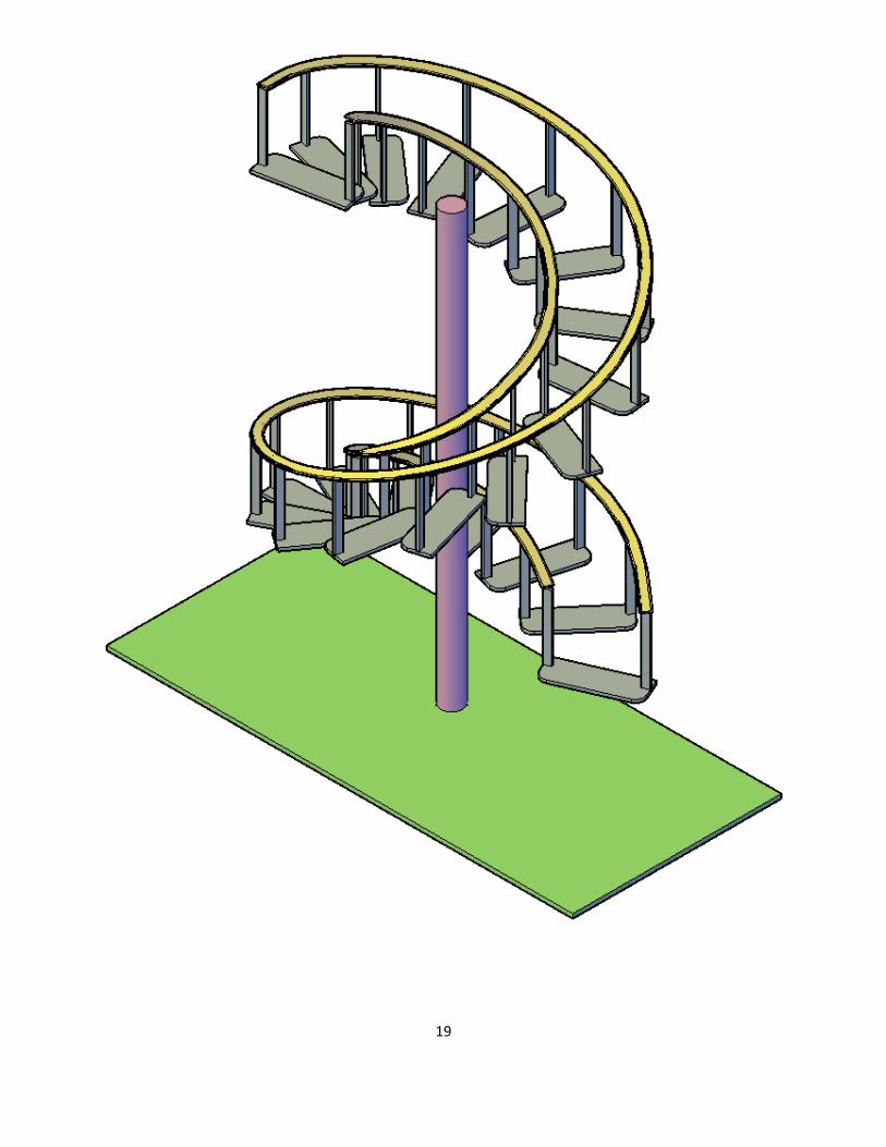
3. Create the following spiral staircase with hand rails. You first need to create a sample stair with the dimensions shown, extruding it
to .75. Next, create a set of hand rail poles of any appropriate size and height, positioned as shown, followed by the floor (any size) and the center pole (height of 120). Then, create a helix, centered on the pole, with the following basic features: height: 120, turns: 1.5, base and top radius: 30, twist: CCW. Finally, position the sample stair at the start of the helix, and perform a path array along that helix, similar to the example in this chapter. You can add the top of the handrail using a sweep of a basic profile—the path used was a spline that hopped from midpoint to midpoint of the top of the rail poles. These are the essential steps, but you have to improvise and experiment to get everything in sync and looking similar to the exercise. Color and shade as needed. (Difficulty level: Difficult; Time to completion: 60–90 minutes.)
19

20
4. Color the faces of an extruded box as follows: top: yellow, left: green, right: purple. Create a hole in the middle as shown. (Difficulty level: Easy; Time to completion: 1–2 minutes.)
5. Color the faces of the following extruded box with any color of your choosing. Offset the hole to a smaller size as shown.
(Difficulty level: Easy; Time to completion: 1–2 minutes.)