CHAPTER 24 CLEANING INSTRUCTIONS – FORKLIFTS
102
UNCONTROLLED IF PRINTED 24-1 ADF Force Extraction Cleaning Manual CHAPTER 24 CLEANING INSTRUCTIONS – FORKLIFTS 24.1 This chapter provides basic cleaning requirements for selected vehicles. Where there is a specific requirement or need to highlight particular problem areas detailed cleaning guides are provided as tables and figures or as Annexes in this chapter. 24.2 Forklifts are very complex pieces of machinery. While all contamination and BRM must be removed, the main areas of concern are: a. external areas, b. cabin, c. belly plate, d. boom and boom housing, e. engine bay, f. reduction hubs, g. hydraulic and electrical cables, h. drive shaft, i. suspension; j. other high risk areas; and k. tyres (new, old and spares). 24.3 All points are not specific to all forklifts. External Areas 24.4 The cleaning instructions for the forklift’s external areas include the points detailed in Table 24-1. Table 24–1: Cleaning Instructions for a Forklift’s External Areas Serial Comments or Tasks Technical Time (hours) 1 All hydraulic rams are to be extended to facilitate cleaning. Hydraulic lines and cabling are to be wiped clean, conduit is to be flushed clean with a high-pressure water cleaner. If necessary, the conduit is to be removed. 2 The boom is to be extended to facilitate cleaning. 3 All attachments that may collect plant, seed and insect matter are to be cleaned and checked. If necessary, the attachments and covers are to be removed to facilitate cleaning. 4 All rubber seals are to be cleaned of soil, plant and insect matter.
Transcript of CHAPTER 24 CLEANING INSTRUCTIONS – FORKLIFTS

UNCONTROLLED IF PRINTED
24-1
ADF Force Extraction Cleaning Manual
CHAPTER 24
CLEANING INSTRUCTIONS – FORKLIFTS
24.1 This chapter provides basic cleaning requirements for selected vehicles. Where there is a specific requirement or need to highlight particular problem areas detailed cleaning guides are provided as tables and figures or as Annexes in this chapter.
24.2 Forklifts are very complex pieces of machinery. While all contamination and BRM must be removed, the main areas of concern are:
a. external areas,
b. cabin,
c. belly plate,
d. boom and boom housing,
e. engine bay,
f. reduction hubs,
g. hydraulic and electrical cables,
h. drive shaft,
i. suspension;
j. other high risk areas; and
k. tyres (new, old and spares).
24.3 All points are not specific to all forklifts.
External Areas
24.4 The cleaning instructions for the forklift’s external areas include the points detailed in Table 24-1.
Table 24–1: Cleaning Instructions for a Forklift’s External Areas
Serial Comments or Tasks Technical Time (hours)
1 All hydraulic rams are to be extended to facilitate cleaning. Hydraulic lines and cabling are to be wiped clean, conduit is to be flushed clean with a high-pressure water cleaner. If necessary, the conduit is to be removed.
2 The boom is to be extended to facilitate cleaning.
3 All attachments that may collect plant, seed and insect matter are to be cleaned and checked. If necessary, the attachments and covers are to be removed to facilitate cleaning.
4 All rubber seals are to be cleaned of soil, plant and insect matter.

UNCONTROLLED IF PRINTED
24-2
ADF Force Extraction Cleaning Manual
Serial Comments or Tasks Technical Time (hours)
5 Lights and mirrors are to be cleaned and damaged items are to be removed to facilitate cleaning.
6 Covers and attachments are to be cleaned and, if necessary, removed to facilitate cleaning.
7 Soil debris collects on the top of the fuel tank, and should be removed. The external sides of the fuel tank are to be inspected and cleaned if necessary.
8 The underside of the vehicle is to be cleaned with high-pressure water
Cabin
24.5 The cleaning instructions for the Forklift’s dashboard include the point detailed in Table 24-2.
Table 24–2: Cleaning Instructions for a Forklift’s Cabin
Serial Comments or Tasks Technical Time (hours)
1 Remove any rubber floor mats and clean floor surface.
2 Remove and clean all door rubbers, internal door panelling and clean all windowsills.
3 Clean behind the dash lining/panelling. Access will be required for inspection.
4 Remove and clean under the seat, including the rubber seat shroud.
5 Remove any non-affixed floor panel if applicable and clean underneath.
6 Remove rubber pedal covers and clean.
7 Clean behind all cabin walls lining/panelling. Access will be required for inspection.
8 All air-conditioning vents must be internally cleaned. Access will be required for inspection
9 Clean inside all joystick controls. Access will be required for inspection.
10 Check cleanliness of cabin roof, both inside and out.
11 Clean ladder to cabin (if fitted) and under each footstep. Note: Some ladders may have hollow frame
12 Internally clean all light covers. Access will be required for inspection.
13 Empty windscreen reservoir.
14 Check for false floor under cabin and remove for cleaning, if applicable.
15 Areas under the dash are difficult to clean. A vacuum and low-pressure compressed air should be used to remove dust and insect debris.
16 Soil debris collects under and behind the cabin rail, and should be removed.
Belly Plate
24.6 The cleaning instructions for a Forklift’s belly plate include the point detailed in Table 24-3.

UNCONTROLLED IF PRINTED
24-3
ADF Force Extraction Cleaning Manual
Table 24–3: Cleaning Instructions for a Forklift’s Belly Plate
Serial Comments or Tasks Technical Time (hours)
1 The belly plate is difficult to clean and requires extensive flushing with a flexible nozzle through the sides and bottom access hole.
Boom and Boom Housing
24.7 The cleaning instructions for a Forklift’s boom and boom housing include the point detailed in Table 24-4.
Table 24–4: Cleaning Instructions for a Forklift’s Boom and Boom Housing
Serial Comments or Tasks Technical Time (hours)
1 All grease is to be removed from the boom housing. This may require the use of degreaser spayed the full internal length of the boom and hot washed to remove contaminants.
2 The boom is to be extended to facilitate cleaning.
3 All hydraulic rams are to be extended to facilitate cleaning.
4 Hydraulic lines and cabling are to be wiped clean,
5 Conduit is to be flushed clean with a high-pressure water cleaner. If necessary, the conduit is to be removed.
Engine Bay
24.8 The cleaning instructions for a Forklift’s engine bay include the point detailed in Table 24-5
Table 24–5: Cleaning Instructions for a Forklift’s Engine Bay
Serial Comments or Tasks Technical Time (hours)
1 Remove air-filter pre-cleaner cover and clean.
2 Remove air-filter and clean with air.
3 Clean inside fan-belt flywheels
4 Check all surfaces of engine block including between tappet covers.
5 Remove belly plates if applicable and clean.
6 Remove all non-affixed engine covers to allow access for cleaning and inspection.
7 Remove all engine cover rubbers for cleaning and inspection.
8 Check engine housing for open-ended or spot-welded hollow support framework - flush to verify cleanliness.
9 The radiator cowling may need to be removed to facilitate the cleaning of the radiator.
10 Flush radiator and oil cooler from both sides to verify fin/core cleanliness.
11 Loosen radiator shroud to let any loose debris fall through after

UNCONTROLLED IF PRINTED
24-4
ADF Force Extraction Cleaning Manual
Serial Comments or Tasks Technical Time (hours)
flushing.
12 Check either side of radiator for vertical hollow support structures. Flush to verify internal cleanliness if present.
13 Check all wiring harnesses for internal cleanliness.
14 Check under all hydraulic looming for cleanliness.
15 Ensure all engine mounts are clean.
16 Ensure that all surfaces of sump and engine block are clean.
17 All water reservoirs must be emptied (excluding radiator).
18 Remove all contaminated grease from universal joints.
19 Internally clean all light covers. Access will be required for inspection.
20 Removing zip-ties and electrical tape that hold electric and process hydraulic hoses together can facilitate the cleaning and inspection
Reduction Hubs
24.9 The cleaning instructions for a Forklift’s reduction hubs (if fitted) include the point detailed in Table 24-6.
Table 24–2: Cleaning Instructions for a Forklift’s Reduction Hubs
Serial Comments or Tasks Technical Time (hours)
1 Soil collects on the top of the reduction hubs and must be removed.
Hydraulic and Electrical Cables
24.10 The cleaning instructions for the Forklift’s hydraulic and electrical cables include the point detailed in Table 24-7.
Table 24–3: Cleaning Instructions for the a Forklift’s Hydraulic and Electrical Cables
Serial Comments or Tasks Technical Time (hours)
1 All electrical and hydraulic lines are to be separated and all grease and soil debris cleaned from in between them.
2.0
Drive Shaft
24.11 The cleaning instructions for a Forklift’s drive shaft include the points detailed in Table 24-8.
Table 24–4: Cleaning Instructions for a Forklift’s Drive Shaft
Serial Comments or Tasks Technical Time (hours)
1 The reduction hub/drive shaft needs to be rotated during the cleaning process to ensure all areas are cleaned.

UNCONTROLLED IF PRINTED
24-5
ADF Force Extraction Cleaning Manual
Serial Comments or Tasks Technical Time (hours)
2 Hydraulic lines are to be separated to facilitate cleaning. Cable ties may need to be removed to ensure all debris is removed from between the cables.
Suspension
24.12 The specific cleaning instructions a forklift’s suspension include those points detailed in Table 24-9.
Table 24-9: Cleaning Instructions for the Forklift’s Suspension
Serial Comments or Tasks Technical Time (hours)
1 Ensure suspension rocker beam mounts on chassis are clean and free of soil, plant and insect material.
2 Mud and other debris collect in the spring seat, where the spring is mounted to the axle assembly, and are difficult to remove from the base of the springs. Ensure that this area is cleaned well.
3 Mud and other debris collect in the inside area on the inner side of the wheel. Ensure that this area is cleaned well.
4 Ensure axles and mounts on chassis are clean and free of soil, plant and insect material.
5 Check wheel arches for hollow support framework – flush if required.
6 Check the inside of wheel rims and brake drums.
7 Check axels and differential.
8 Remove all contaminated grease from universal joints.
Other High Risk Areas
24.13 The cleaning instructions for a forklift’s other high risk areas include the points detailed in Table 24-10.
Table 24–10: Cleaning Instructions for the Forklift’s Other High Risk Areas
Serial Comments or Tasks Technical Time (hours)
1 Check battery box – loosen batteries and clean under.
2 Check all surfaces of oil tank to ensure clean.
3 Check all surfaces of fuel cell to ensure clean.
4 Check the internal of all light covers & cavities behind.
Tyres (New, Old and Spares)
24.14 The cleaning instructions for Tyres (New, Old and Spares) include the points detailed in Table 24-11.

UNCONTROLLED IF PRINTED
24-6
ADF Force Extraction Cleaning Manual
Table 24–11: Cleaning Instructions for Tyres (New, Old and Spares)
Serial Comments or Tasks Technical Time (hours)
1 All tyres are to be washed and scrubbed to remove all BRM.
2 Damaged tyres are to be inspected and their suitability for return to Australia determined. If necessary, damaged tyres (for example, perished, cracked or split) are to be removed and disposed of in accordance with the tyre disposal policy.
3 Cracked tyres have the risk of containing BRM therefore perished tyres are to be subject to disposal.
4 All tyres are to be treated with an approved residual insecticide after cleaning
5 Fitted tyres that are damaged should be replaced with new tyres.
6 Used and fitted tyres on rims are to be individually verified that the tyres are on rims, inflated with beading sealed and that the tyres are clean, free of water and other BRM.
7 Tyres that are not fitted to rims are to be stored in such a manner that water cannot collect inside the tyre. The preferred DA solution is that tyres are stored within containers. Tyres not fitted on rims will require fumigation on return to Australia.
8 DA considers a Non-Commercial consignment of tyres to contain a maximum of 8 tyres (inclusive of the wheels on the vehicle) and be imported with an accompanying vehicle. If tyres are to be transported back to Australia in containers or crates, please refer to the DA BICON (Biosecurity Import Conditions system) internet site (http://www.agriculture.gov.au/import/online-services/bicon) for the commodity “tyres”.
Annexes:
A. Cleaning Instructions - Forklift Caterpillar 3 tonne B. Cleaning Instructions - Forklift Manitou MHT 7140L C. Cleaning Instructions - Forklift Merlo Panoramic D. Cleaning Instructions - Forklift Toyota Commercial on Pavement E. Cleaning Instructions - Forklift SMV 32 tonne F. Cleaning Instructions - Forklift TCM FD70Z8 4500KG G. Cleaning Instructions - Forklift Pacific ATF250 25 Tonne Rough Terrain H. Cleaning Instructions - Forklift Manitou M50-4 I. Cleaning Instructions - Forklift Case W36 J. Cleaning Instructions - Forklift Manitou MT932 K. Cleaning Instructions - Forklift Manitou MHT 1060L Turbo L. Cleaning Instructions - Forklift Hitachi LX120 M. Cleaning Checklist - Forklifts

UNCONTROLLED IF PRINTED
24A-1
ADF Force Extraction Cleaning Manual
ANNEX A TO CHAPTER 24
CLEANING INSTRUCTIONS – FORKLIFT CATERPILLAR 3 TONNE
1. This annex provides basic and specific cleaning requirements for selected vehicles. Where there is a specific requirement or need to highlight particular problem areas detailed cleaning guides are provided as tables and figures in this annex.
2. The cleaning requirements that follow are in addition to those points for forklifts included in Chapter 24 of this publication.
External Areas
3. The cleaning instructions for the Caterpillar 3 Tonne Forklift’s external areas, as illustrated in Figure 24A-1 to 24A-6, include the points detailed in Table 24A-1.
Figure 24A–1: Caterpillar 3 Tonne Forklift’s External Areas
Figure 24A–2: Caterpillar 3 Tonne Forklift’s Cab air filter

UNCONTROLLED IF PRINTED
24A-2
ADF Force Extraction Cleaning Manual
Figure 24A–3: Caterpillar 3 Tonne Forklift’s Cab Air Intake
Figure 24A–4: Caterpillar 3 Tonne Forklift’s Fuel Tank Outside
Figure 24A–5: Caterpillar 3 Tonne Forklift’s Tool Draw

UNCONTROLLED IF PRINTED
24A-3
ADF Force Extraction Cleaning Manual
Table 24A–1: Cleaning Instructions for a Caterpillar 3 Tonne Forklift’s External Areas
Serial Comments or Tasks Technical Time (hours)
1 Air-conditioning filters are to be removed and air vents unscrewed and cleaned by a high-pressure air clean (refer Figures 24A-2 and 24A3).
2 Soil debris collects on the top of the fuel tank, and should be removed. The external sides of the fuel tank are to be inspected and cleaned if necessary (refer Figure 24A-4).
3 The tool drawer is to be emptied and both the contents and the draw are to be cleaned and, if necessary, removed to facilitate cleaning (refer Figure 24A-5).
4 Refer to Chapter 24 for detailed cleaning guidelines.
Cabin
4. The cleaning instructions for the Caterpillar 3 Tonne Forklift’s cabin, as illustrated in Figure 24A-6 and 24A-8, include the points detailed in Table 24A-1.
Figure 24A–6: Caterpillar 3 Tonne Forklift’s Dash Panel & Air Vents
Figure 24A–7: Caterpillar 3 Tonne Forklift’s Seat Suspension

UNCONTROLLED IF PRINTED
24A-4
ADF Force Extraction Cleaning Manual
Figure 24A–8: Caterpillar 3 Tonne Forklift’s Fuse Box
Table 24A–2: Cleaning Instructions for a Caterpillar 3 Tonne Forklift’s Cabin
Serial Comments or Tasks Technical Time (hours)
1 Areas under the dash are difficult to clean. A vacuum and low-pressure compressed air should be used to remove dust and insect debris (refer Figure 24A-6).
2 All air-conditioning vents must be internally cleaned. Access will be required for inspection (refer Figure 24A-6).
3 Remove and clean under the seat, including the rubber seat shroud (refer Figure 24A-7).
4 Internally clean the fuse box compartment. Access will be required for inspection (refer Figure 24A-8).
5 Refer to Chapter 24 for detailed cleaning guidelines.
Boom and Boom Housing
5. The cleaning instructions for a Caterpillar 3 Tonne Forklift’s boom and boom, as illustrated in Figure 24A-9 to 24A-13, include the points detailed in Table 24A-3.

UNCONTROLLED IF PRINTED
24A-5
ADF Force Extraction Cleaning Manual
Figure 24A–9: Caterpillar 3 Tonne Forklift’s Front Areas
Figure 24A–10: Caterpillar 3 Tonne Forklift’s Telescopic Boom

UNCONTROLLED IF PRINTED
24A-6
ADF Force Extraction Cleaning Manual
Figure 24A–21: Caterpillar 3 Tonne Forklift’s Under Boom
Figure 24A–12: Caterpillar 3 Tonne Forklift’s Inside Boom Front
Figure 24A–13: Caterpillar 3 Tonne Forklift’s Inside Boom Rear

UNCONTROLLED IF PRINTED
24A-7
ADF Force Extraction Cleaning Manual
Table 24A–3: Cleaning Instructions for a Caterpillar 3 Tonne Forklift’s Boom and Boom Housing
Serial Comments or Tasks Technical Time (hours)
1 The boom is to be extended to facilitate cleaning (refer Figure 24A-10).
2 All grease is to be removed from the boom housing especially the underside of the boom (refer Figure 24A-11). This may require the use of degreaser spayed the full internal length of the boom and hot washed to remove contaminants.
3 Special attention is to be made on the inside boom front (refer Figure 24A-12) and the inside boom rear (refer Figure 24A-13). Ensure all areas are clear of insect and plant material.
4 Refer to Chapter 24 for detailed cleaning guidelines.
Engine Bay
6. The cleaning instructions for a Caterpillar 3 Tonne Forklift’s engine, as illustrated in Figure 24A-14 and 24A-16, include the points detailed in Table 24A-4.
Figure 24A–14: Caterpillar 3 Tonne Forklift’s Engine Bay
Figure 24A–15: Caterpillar 3 Tonne Forklift’s Air Cleaner

UNCONTROLLED IF PRINTED
24A-8
ADF Force Extraction Cleaning Manual
Figure 24A–16: Caterpillar 3 Tonne Forklift’s Radiator & Air Conditioner
Table 24A–4: Cleaning Instructions for a Caterpillar 3 Tonne Forklift’s Engine Bay
Serial Comments or Tasks Technical Time (hours)
1 Remove air cleaner and ensure housing is clear of insect and plant material. Dispose of used air cleaner element (refer Figure 24A-15).
2 The radiator cowling may need to be removed to facilitate the cleaning of the radiator (refer Figure 24A-16).
0.5
3 Refer to Chapter 24 for detailed cleaning guidelines.
Hydraulic and Electrical Cables
7. The cleaning instructions for the Caterpillar 3 Tonne Forklift’s hydraulic and electrical, as illustrated in Figure 24A-17 and 24A-18, include the points detailed in Table 24A-5.

UNCONTROLLED IF PRINTED
24A-9
ADF Force Extraction Cleaning Manual
Figure 24A–17: Caterpillar 3 Tonne Forklift’s Rear LHS Hydraulic
Figure 24A–18: Caterpillar 3 Tonne Forklift’s Fork Hydraulics
Table 24A –2: Cleaning Instructions for the a Caterpillar 3 Tonne Forklift’s Hydraulic and Electrical Cables
Serial Comments or Tasks Technical Time (hours)
1 All electrical and hydraulic lines are to be separated and all grease and soil debris cleaned from in between them (refer Figures 24A-17 and 24A-18).
2.0
2 Refer to Chapter 24 for detailed cleaning guidelines.


UNCONTROLLED IF PRINTED
24B-1
ADF Force Extraction Cleaning Manual
ANNEX B TO CHAPTER 24
CLEANING INSTRUCTIONS – FORKLIFT MANITOU MHT 7140L
1. This annex provides basic and specific cleaning requirements for selected vehicles. Where there is a specific requirement or need to highlight particular problem areas detailed cleaning guides are provided as tables and figures in this annex.
2. The cleaning requirements that follow are in addition to those points for forklifts included in Chapter 24 of this publication.
External Areas
3. The cleaning instructions for the Manitou Forklift’s external, as illustrated in Figures 24B-1 to 24B-4, include the points detailed in Table 24B-1.
Figure 24B-1: Manitou Forklift’s External Areas
Figure 24B-2: Manitou Forklift’s Battery Box

UNCONTROLLED IF PRINTED
24B-2
ADF Force Extraction Cleaning Manual
Figure 24B-3: Manitou Forklift’s Air Compressor
Figure 24B-4: Manitou Forklift’s Mud Guard
Table 24B–1: Cleaning Instructions for a Manitou Forklift’s External Areas
Serial Comments or Tasks Technical Time (hours)
1 All attachments that may collect plant, seed and insect matter are to be removed, checked and cleaned. Once removed, all external areas of the forklift are to be cleaned clean (refer Figure 24B- 1).
2 Remove battery and clean battery box and terminals (refer Figure 24B- 2).
3 Remove air compressor and ensure housing is clear of insect and plant material. Dispose of used air cleaner element (refer Figure 24B-3).
4 Special attention is to be paid on the mudguards which are to be cleaned with high-pressure water terminals (refer Figure 24B- 4).
5 Refer to Chapter 24 for detailed cleaning guides.
Cabin
4. The cleaning instructions for the Manitou Forklift’s cabin, as illustrated in Figures 24B-5 to 24B-9, include the points detailed in Table 24B-2.

UNCONTROLLED IF PRINTED
24B-3
ADF Force Extraction Cleaning Manual
Figure 24B-5: Manitou Forklift’s Cab Front (Left) and Door (Right)
Figure 24B-6: Manitou Forklift’s Cab Dust Seal
Figure 24B-7: Manitou Forklift’s Dash Vents
UNCONTROLLED IF PRINTED
24B-4
ADF Force Extraction Cleaning Manual
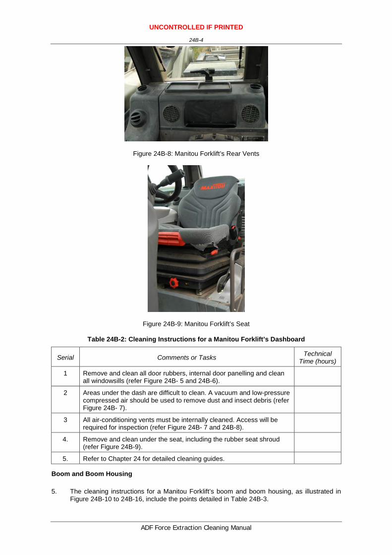
Figure 24B-8: Manitou Forklift’s Rear Vents
Figure 24B-9: Manitou Forklift’s Seat
Table 24B-2: Cleaning Instructions for a Manitou Forklift’s Dashboard
Serial Comments or Tasks Technical Time (hours)
1 Remove and clean all door rubbers, internal door panelling and clean all windowsills (refer Figure 24B- 5 and 24B-6).
2 Areas under the dash are difficult to clean. A vacuum and low-pressure compressed air should be used to remove dust and insect debris (refer Figure 24B- 7).
3 All air-conditioning vents must be internally cleaned. Access will be required for inspection (refer Figure 24B- 7 and 24B-8).
4. Remove and clean under the seat, including the rubber seat shroud (refer Figure 24B-9).
5. Refer to Chapter 24 for detailed cleaning guides.
Boom and Boom Housing
5. The cleaning instructions for a Manitou Forklift’s boom and boom housing, as illustrated in Figure 24B-10 to 24B-16, include the points detailed in Table 24B-3.

UNCONTROLLED IF PRINTED
24B-5
ADF Force Extraction Cleaning Manual
Figure 24B-10: Manitou Forklift’s Boom Extended
Figure 24B-11: Manitou Forklift’s Boom Extension Slides
Figure 24B-12: Manitou Forklift’s Boom Inspection Panel Front

UNCONTROLLED IF PRINTED
24B-6
ADF Force Extraction Cleaning Manual
Figure 24B-23: Manitou Forklift’s Boom Ram Area
Figure 24B-34: Manitou Forklift’s Hydraulic Dist
Figure 24B-45: Manitou Forklift’s Boom Ram Area

UNCONTROLLED IF PRINTED
24B-7
ADF Force Extraction Cleaning Manual
Figure 24B-56: Manitou Forklift’s Rear of Front Forks
Table 24–3: Cleaning Instructions for a Manitou Forklift’s Boom and Boom Housing
Serial Comments or Tasks Technical Time (hours)
1 The boom is to be extended to facilitate cleaning (refer Figure 24B-60).
2 All hydraulic rams are to be extended to facilitate cleaning. Hydraulic lines and cabling are to be wiped clean, conduit is to be flushed clean with a high-pressure water cleaner (refer figures 24B-71 to 24B-86).
3 All grease is to be removed from the boom housing. This may require the use of degreaser spayed the full internal length of the boom and hot washed to remove contaminants.
4 Refer to Chapter 24 for detailed cleaning guides.
Engine Bay
6. The cleaning instructions for a Manitou Forklift’s engine, as illustrated in Figure 24B-97 to 24B-21, include the points detailed in Table 24B-4.
Figure 24B-107: Manitou Forklift’s Engine Bay

UNCONTROLLED IF PRINTED
24B-8
ADF Force Extraction Cleaning Manual
Figure 24B-18: Manitou Forklift’s Air Filter
Figure 24B-119: Manitou Forklift’s Engine Bay
Figure 24B-20: Manitou Forklift’s Radiator & Oil Cooler

UNCONTROLLED IF PRINTED
24B-9
ADF Force Extraction Cleaning Manual
Figure 24B-21: Manitou Forklift’s Radiator & Heat Exchanger
Table 24–4: Cleaning Instructions for a Manitou Forklift’s Engine Bay
Serial Comments or Tasks Technical Time (hours)
1 Remove air-filter pre-cleaner cover and clean (refer 24B-17).
2 Remove air-filter and clean with air (refer 24B-18).
3 Open engine bay cover and clean to ensure freedom of BRM (refer 24B-19).
4 The radiator cowling may need to be removed to facilitate the cleaning of the radiator (refer 24B-19 and 24B-20).
5 Flush radiator and oil cooler from both sides to verify fin/core cleanliness.
6 Loosen radiator shroud to let any loose debris fall through after flushing.
7 Check either side of radiator for vertical hollow support structures. Flush to verify internal cleanliness if present.
8 Refer to Chapter 24 for detailed cleaning guides.
Hydraulic and Electrical Cables
7. The cleaning instructions for the Manitou Forklift’s hydraulic and electrical, as illustrated in Figures 24B-22 and 24B-23, include the points detailed in Table 24B-5.

UNCONTROLLED IF PRINTED
24B-10
ADF Force Extraction Cleaning Manual
Figure 24B-22: Manitou Forklift’s Hydraulic Hoses
Figure 24B-23: Manitou Forklift’s Electrical Compartment
Table 24–5: Cleaning Instructions for the a Manitou Forklift’s Hydraulic and Electrical Cables
Serial Comments or Tasks Technical Time (hours)
1 All electrical and hydraulic lines are to be separated and all grease and soil debris cleaned from in between them (refer Figure 24B-22).
2 Ensure the electrical compartment on the left-hand side rear of cabin is opened and cleaned of all BRM. Do not use water within this area (refer Figure 24B-23).
Tail Light Electronics
8. The cleaning instructions for the Manitou Forklift’s tail light electricals, as illustrated in Figure 24B-24, include the points detailed in Table 24B-6.

UNCONTROLLED IF PRINTED
24B-11
ADF Force Extraction Cleaning Manual
Figure 24B-24: Manitou Forklift’s Tail Light Electronics
Table 24–6: Cleaning Instructions for the a Manitou Forklift’s Tail Light Electronics
Serial Comments or Tasks Technical Time (hours)
1 Ensure the rear tail lights do not become wet during cleaning or steam cleaned as the electronics are easily damaged. Do not use water within this area (refer Figure 24B-24).


UNCONTROLLED IF PRINTED
24C-1
ADF Force Extraction Cleaning Manual
ANNEX C TO CHAPTER 24
CLEANING INSTRUCTIONS – MERLO PANORAMIC 4X4
1. This annex provides basic and specific cleaning requirements for selected vehicles. Where there is a specific requirement or need to highlight particular problem areas detailed cleaning guides are provided as tables and figures in this annex.
2. The cleaning requirements that follow are in addition to those points for forklifts included in Chapter 24 of this publication.
External Areas
3. The cleaning instructions for the Merlo Panoramic’s external areas, as illustrated in Figures 24C-1 to 24C-3, include the points detailed in Table 24C-1.
Figure 24C-1: Merlo Panoramic’s External Areas
Figure 24C-2: Merlo Panoramic’s External Areas
UNCONTROLLED IF PRINTED
24C-2
ADF Force Extraction Cleaning Manual
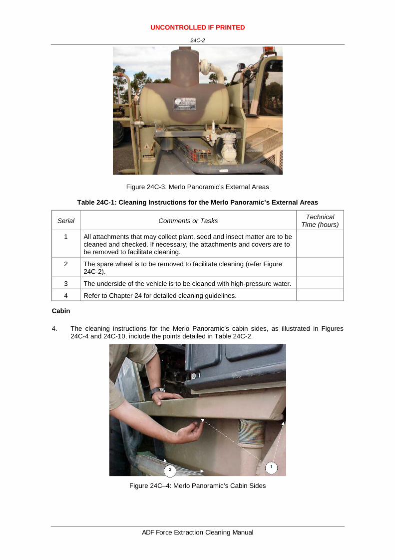
Figure 24C-3: Merlo Panoramic’s External Areas
Table 24C-1: Cleaning Instructions for the Merlo Panoramic’s External Areas
Serial Comments or Tasks Technical Time (hours)
1 All attachments that may collect plant, seed and insect matter are to be cleaned and checked. If necessary, the attachments and covers are to be removed to facilitate cleaning.
2 The spare wheel is to be removed to facilitate cleaning (refer Figure 24C-2).
3 The underside of the vehicle is to be cleaned with high-pressure water.
4 Refer to Chapter 24 for detailed cleaning guidelines.
Cabin
4. The cleaning instructions for the Merlo Panoramic’s cabin sides, as illustrated in Figures 24C-4 and 24C-10, include the points detailed in Table 24C-2.
Figure 24C–4: Merlo Panoramic’s Cabin Sides

UNCONTROLLED IF PRINTED
24C-3
ADF Force Extraction Cleaning Manual
Figure 24C–5: Merlo Panoramic’s Cabin Seat and Seat Shroud
Figure 24C–6: Merlo Panoramic’s Instrument Panel
Figure 24C–7: Merlo Panoramic’s Under Dashboard

UNCONTROLLED IF PRINTED
24C-4
ADF Force Extraction Cleaning Manual
Figure 24C–8: Merlo Panoramic’s Cabin Sides
Figure 24C–9: Merlo Panoramic’s Behind the Seat Air-conditioner and Vents
Table 24C–2: Cleaning Instructions for the Merlo Panoramic’s Cabin Sides
Serial Comments or Tasks Technical Time (hours)
1 Soil debris collects under and behind the cabin rail, and should be removed (refer Figure 2-.
2 Soil debris collects on the top of the fuel tank, and should be removed.
3 Areas under the dash are difficult to clean. A vacuum and low-pressure compressed air should be used to remove dust and insect debris (refer Figure 24C-3).
4 Refer to Chapter 24 for detailed cleaning guidelines.
Belly Plate
5. The cleaning instructions for the Merlo Panoramic’s belly plate, as illustrated in Figure 24C-10, include the point detailed in Table 24C-3.

UNCONTROLLED IF PRINTED
24C-5
ADF Force Extraction Cleaning Manual
Figure 24C–10: Merlo Panoramic’s Belly Plate
Table 24C–3: Cleaning Instructions for the Merlo Panoramic’s Belly Plate
Serial Comments or Tasks Technical Time (hours)
1 The belly plate is difficult to clean and requires extensive flushing with a flexible nozzle through the sides and bottom access hole.
Boom Housing
6. The cleaning instructions for the Merlo Panoramic’s boom housing, as illustrated in Figure 24C-11, include the point detailed in Table 24C-4.
Figure 24C–11: Merlo Panoramic’s Boom Housing
Table 24C–4: Cleaning Instructions for the Merlo Panoramic’s Boom Housing
Serial Comments or Tasks Technical Time (hours)
1 All grease is to be removed from the boom housing. This may require the use of degreaser spayed the full internal length of the boom and hot washed to remove contaminants.
2 Refer to Chapter 24 for detailed cleaning guidelines.

UNCONTROLLED IF PRINTED
24C-6
ADF Force Extraction Cleaning Manual
Engine Bay
7. The cleaning instructions for the Merlo Panoramic’s radiator, as illustrated in Figures 24C-12 to 24C-14, include the point detailed in Table 24C-5
Figure 24C–12: Merlo Panoramic’s Engine Bay
Figure 24C–13: Merlo Panoramic’s Engine Bay Covers Removed
Figure 24C–14: Merlo Panoramic’s Radiator

UNCONTROLLED IF PRINTED
24C-7
ADF Force Extraction Cleaning Manual
Table 24C–5: Cleaning Instructions for the Merlo Panoramic’s Radiator
Serial Comments or Tasks Technical Time (hours)
1 The radiator cowling may need to be removed to facilitate the cleaning of the radiator.
0.5
2 Refer to Chapter 24 for detailed cleaning guidelines.
Reduction Hubs
8. The cleaning instructions for the Merlo Panoramic’s reduction hubs, as illustrated in Figure 24C-15, include the point detailed in Table 24C-6.
Figure 24C–15: Merlo Panoramic’s Reduction Hubs
Table 24V–2: Cleaning Instructions for the Merlo Panoramic’s Reduction Hubs
Serial Comments or Tasks Technical Time (hours)
1 Soil collects on the top of the reduction hubs and must be removed.
Hydraulic and Electrical Cables
9. The cleaning instructions for the Merlo Panoramic’s hydraulic and electrical cable, as illustrated in Figure 24C-16, include the point detailed in Table 24C-7.

UNCONTROLLED IF PRINTED
24C-8
ADF Force Extraction Cleaning Manual
Figure 24C–16: Merlo Panoramic’s Hydraulic and Electrical Cables
Table 24C–3: Cleaning Instructions for the Merlo Panoramic’s Hydraulic and Electrical Cables
Serial Comments or Tasks Technical Time (hours)
1 All electrical and hydraulic lines are to be separated and all grease and soil debris cleaned from in between them.
2.0
Drive Shaft
10. The cleaning instructions for the Merlo Panoramic’s drive shaft, as illustrated in Figure 24C-17, include the points detailed in Table 24C-8.
Figure 24C–17: Merlo Panoramic’s Drive Shaft

UNCONTROLLED IF PRINTED
24C-9
ADF Force Extraction Cleaning Manual
Table 24C–4: Cleaning Instructions for the Merlo Panoramic’s Drive Shaft
Serial Comments or Tasks Technical Time (hours)
1 The reduction hub/drive shaft needs to be rotated during the cleaning process to ensure all areas are cleaned.
2 Hydraulic lines are to be separated to facilitate cleaning. Cable ties may need to be removed to ensure all debris is removed from between the cables.
Suspension
11. The specific cleaning instructions a forklift’s suspension, as illustrated in Figure 24C-18, include those points detailed in Table 24C-9.
Figure 24C–18: Merlo Panoramic’s Rear Suspension
Table 24C-9: Cleaning Instructions for the Forklift’s Suspension
Serial Comments or Tasks Technical Time (hours)
1 Ensure suspension rocker beam mounts on chassis are clean and free of soil, plant and insect material.
2 Refer to Chapter 24 for detailed cleaning guidelines.
Other High Risk Areas
12. Cleaning instructions for a forklift’s other high risk areas include the points detailed in Table 24C-10.

UNCONTROLLED IF PRINTED
24C-10
ADF Force Extraction Cleaning Manual
Figure 24C–19: Merlo Panoramic’s Battery Bay
Table 24–10: Cleaning Instructions for the Forklift’s Other High Risk Areas
Serial Comments or Tasks Technical Time (hours)
1 Check battery box – loosen batteries and clean under.
2 Check all surfaces of oil tank to ensure clean.
3 Check all surfaces of fuel cell to ensure clean.
4 Check the internal of all light covers & cavities behind.
5 Refer to Chapter 24 for detailed cleaning guidelines.

UNCONTROLLED IF PRINTED
24D-1
ADF Force Extraction Cleaning Manual
ANNEX D TO CHAPTER 24
CLEANING INSTRUCTIONS – FORKLIFT TOYOTA ON PAVEMENT
1. This annex provides basic and specific cleaning requirements for selected vehicles. Where there is a specific requirement or need to highlight particular problem areas detailed cleaning guides are provided as tables and figures in this annex.
2. The cleaning requirements that follow are in addition to those points for forklifts included in Chapter 24 of this publication.
3. While all contamination and BRM must be removed, the main areas of concern are:
a. external areas,
b. cabin area,
c. boom and boom housing, and
d. engine bay.
External Areas
4. The cleaning instructions for the Toyota Forklift’s external areas, as illustrated in Figure 24D-1, include the points detailed in Table 24D-1.
Figure 24D–1: Toyota Forklift’s External Areas
Table 24D–1: Cleaning Instructions for a Toyota Forklift’s External Areas
Serial Comments or Tasks Technical Time (hours)
1 Refer to Chapter 24 for detailed cleaning instructions.

UNCONTROLLED IF PRINTED
24D-2
ADF Force Extraction Cleaning Manual
Cabin Area
5. The cleaning instructions for the Toyota Forklift’s dashboard, as illustrated in Figures 24D-2 to 24D-4, include the points detailed in Table 24D-1.
Figure 24D–2: Toyota Forklift’s Cabin Area
Figure 24D–3: Toyota Forklift’s Rear

UNCONTROLLED IF PRINTED
24D-3
ADF Force Extraction Cleaning Manual
Figure 24D–4: Toyota Forklift’s Controls and Instrument Panel
Table 24D–2: Cleaning Instructions for a Toyota Forklift’s Dashboard
Serial Comments or Tasks Technical Time (hours)
1 Remove and clean under the seat, including the rubber seat shroud (refer Figure 24D-4).
2 Remove rubber pedal covers and clean.
3 Clean inside all joystick controls. Access will be required for inspection.
4 Areas under the dash are difficult to clean. A vacuum and low-pressure compressed air should be used to remove dust and insect debris.
5 Refer to Chapter 24 for detailed cleaning instructions.
Boom and Boom Housing
6. The cleaning instructions for a Toyota Forklift’s boom and boom, as illustrated in Figures 24D-5 to 24D-7, include the points detailed in Table 24D-3.
Figure 24D–5: Toyota Forklift’s Boom and Boom Housing

UNCONTROLLED IF PRINTED
24D-4
ADF Force Extraction Cleaning Manual
Figure 24D–6: Toyota Forklift’s Hydraulic Rams
Figure 24D–7: Toyota Forklift’s Lift Boom
Table 24D–3: Cleaning Instructions for a Toyota Forklift’s Boom and Boom Housing
Serial Comments or Tasks Technical Time (hours)
1 All grease is to be removed from the boom housing. This may require the use of degreaser spayed the full internal length of the boom and hot washed to remove contaminants (Refer Figure 24D-5).
2 All hydraulic rams are to be extended to facilitate cleaning (refer Figure 24D-6).
3 The boom is to be extended to facilitate cleaning (refer Figure 24D-7).
4 Refer to Chapter 24 for detailed cleaning instructions.

UNCONTROLLED IF PRINTED
24D-5
ADF Force Extraction Cleaning Manual
Engine Bay
7. The cleaning instructions for a Forklift’s engine bay, as illustrated in Figures 24D-8 to 24D-11, include the point detailed in Table 24D-4
Figure 24D–8: Toyota Forklift’s Radiator
Figure 24D–9: Toyota Forklift’s Engine Bay
Figure 24D–20: Toyota Forklift’s Engine Left and Right Side Views

UNCONTROLLED IF PRINTED
24D-6
ADF Force Extraction Cleaning Manual
Figure 24D–31: Toyota Forklift’s Battery Bay
Table 24D–4: Cleaning Instructions for a Forklift’s Engine Bay
Serial Comments or Tasks Technical Time (hours)
1 Clean inside fan-belt flywheels (refer Figure 24D-8).
2 The radiator cowling may need to be removed to facilitate the cleaning of the radiator.
3 Flush radiator and oil cooler from both sides to verify fin/core cleanliness.
4 Loosen radiator shroud to let any loose debris fall through after flushing.
5 Check either side of radiator for vertical hollow support structures. Flush to verify internal cleanliness if present.
6 Check all wiring harnesses and hydraulic looming for internal cleanliness (refer Figure 24D-9).
7 Ensure that all surfaces of sump and engine block are clean (refer Figure 24D-10).
8 All water reservoirs must be emptied (excluding radiator).
9 Check battery box – loosen batteries and clean under (refer Figure 24D-11).
10 Refer to Chapter 24 for detailed cleaning instructions.

UNCONTROLLED IF PRINTED
24E-1
ADF Force Extraction Cleaning Manual
ANNEX E TO CHAPTER 24
CLEANING INSTRUCTIONS – FORKLIFT SMV 32 TONNE
1. This annex provides basic and specific cleaning requirements for selected vehicles. Where there is a specific requirement or need to highlight particular problem areas detailed cleaning guides are provided as tables and figures in this annex.
2. The cleaning requirements that follow are in addition to those points for forklifts included in Chapter 24E of this publication.
3. All points are not specific to all forklifts.
External Areas
4. The cleaning instructions for the SMV 32 Tonne Forklift’s external areas, as illustrated in Figures 24E-1 to 24E7, include the points detailed in Table 24E-1.
Figure 24E–1: SMV 32 Tonne Forklift’s External Areas

UNCONTROLLED IF PRINTED
24E-2
ADF Force Extraction Cleaning Manual
Figure 24E–2: SMV 32 Tonne Forklift’s Covers Under Stairs Area
Figure 24E-3: SMV 32 Tonne Forklift’s Cab Lifting Controller Cabinet
Figure 24E–4: SMV 32 Tonne Forklift’s Front of Cab

UNCONTROLLED IF PRINTED
24E-3
ADF Force Extraction Cleaning Manual
Figure 24E-5: SMV 32 Tonne Forklift’s Under Cab
Figure 24E–6: SMV 32 Tonne Forklift’s Counterweights

UNCONTROLLED IF PRINTED
24E-4
ADF Force Extraction Cleaning Manual
Figure 24E–7: SMV 32 Tonne Forklift’s Battery Box
Table 24E–1: Cleaning Instructions for a SMV 32 Tonne Forklift’s External Areas
Serial Comments or Tasks Technical Time (hours)
1 Ensure the covers under stairs are inspected and cleaned if required (refer 24E-2).
2 Ensure the cab lifting controllers compartment is cleaned (refer 24E-3).
3 Ensure the under area of the front of cab is cleaned if required (refer 24E-4).
4 Ensue the area under the cabin floor is subject to cleaning (refer Figure 24E-5.
5 The area behind the forklift’s counterweights must be cleaned of all BRM (refer 24E-6).
6 Remove battery and clean battery box and terminals (refer Figure 24E-7).
7 Refer to Chapter 24 for detailed cleaning guides.
Cabin
5. The cleaning instructions for the SMV 32 Tonne Forklift’s dashboard, as illustrated in Figures 24E-8 and 24E-9, include the points detailed in Table 24E-2.

UNCONTROLLED IF PRINTED
24E-5
ADF Force Extraction Cleaning Manual
Figure 24E-8: SMV 32 Tonne Forklift’s Bab Vents & Panels
Figure 24E-9: SMV 32 Tonne Forklift’s Dash Vents
Table 24E–2: Cleaning Instructions for a SMV 32 Tonne Forklift’s Dashboard
Serial Comments or Tasks Technical Time (hours)
1 All air-conditioning vents must be internally cleaned. Access will be required for inspection (refer Figure 24E-8)
2 Areas under the dash are difficult to clean. A vacuum and low-pressure compressed air should be used to remove dust and insect debris (refer Figure 24E-9).
3 Refer to Chapter 24 for detailed cleaning guides.
Belly Plate
6. The cleaning instructions for a SMV 32 Tonne Forklift’s belly plate, as illustrated in Figure 24E-10, include the points detailed in Table 24E-3.

UNCONTROLLED IF PRINTED
24E-6
ADF Force Extraction Cleaning Manual
Figure 24E-20: SMV 32 Tonne Forklift’s External Areas
Table 24E–3: Cleaning Instructions for a SMV 32 Tonne Forklift’s Belly Plate
Serial Comments or Tasks Technical Time (hours)
1 The belly plate is difficult to clean and requires extensive flushing with a flexible nozzle through the sides and bottom access hole.
2 Refer to Chapter 24 for detailed cleaning guides.
Boom and Boom Housing
7. The cleaning instructions for a SMV 32 Tonne Forklift’s boom and boom , as illustrated in Figures 24E-11 and 24E-12, include the points detailed in Table 24E-4.
Figure 24E–13: SMV 32 Tonne Forklift’s Front Angle

UNCONTROLLED IF PRINTED
24E-7
ADF Force Extraction Cleaning Manual
Figure 24E-42: SMV 32 Tonne Forklift’s Front Forks
Table 24E–4: Cleaning Instructions for a SMV 32 Tonne Forklift’s Boom and Boom Housing
Serial Comments or Tasks Technical Time (hours)
1 All grease is to be removed from the boom housing. This may require the use of degreaser spayed the full internal length of the boom and hot washed to remove contaminants.
2 The boom is to be extended to facilitate cleaning.
3 All hydraulic rams are to be extended to facilitate cleaning. Hydraulic lines and cabling are to be wiped clean, conduit is to be flushed clean with a high-pressure water cleaner. If necessary, the conduit is to be removed.
4 Refer to Chapter 24 for detailed cleaning guides.
Engine Bay
8. The cleaning instructions for a SMV 32 Tonne Forklift’s engine, as illustrated in Figure 24E-13, include the points detailed in Table 24E-5.

UNCONTROLLED IF PRINTED
24E-8
ADF Force Extraction Cleaning Manual
Figure 24E-53: SMV 32 Tonne Forklift’s Engine Bay
Table 24E–5: Cleaning Instructions for a SMV 32 Tonne Forklift’s Engine Bay
Serial Comments or Tasks Technical Time (hours)
1 The radiator cowling may need to be removed to facilitate the cleaning of the radiator.
0.5
2 Refer to Chapter 24 for detailed cleaning guides.
Suspension
9. The cleaning instructions for a SMV 32 Tonne Forklift’s suspension as illustrated in Figure 24E-14, include the points detailed in Table 24E-6.
Figure 24E–64: SMV 32 Tonne Forklift’s Wheels

UNCONTROLLED IF PRINTED
24E-9
ADF Force Extraction Cleaning Manual
Table 24E–2: Cleaning Instructions for a SMV 32 Tonne Forklift’s Suspension
Serial Comments or Tasks Technical Time (hours)
1 Soil collects on the top of the inner hubs and axles and must be removed (refer Figure 14).
2 Refer to Chapter 24 for detailed cleaning guides.


UNCONTROLLED IF PRINTED
24F-1
ADF Force Extraction Cleaning Manual
ANNEX F TO CHAPTER 24
CLEANING INSTRUCTIONS – FORKLIFT TCM FD70Z8 4500KG
1. This annex provides basic and specific cleaning requirements for selected vehicles. Where there is a specific requirement or need to highlight particular problem areas detailed cleaning guides are provided as tables and figures in this annex.
2. The cleaning requirements that follow are in addition to those points for forklifts included in Chapter 24 of this publication.
3. While all contamination and BRM must be removed, the main areas of concern are:
a. external areas,
b. cabin area, and
c. boom and boom housing,
External Areas
4. The cleaning instructions for the TCM Forklift’s external areas, as illustrated in Figures 24F-1 and 24F-2, include the points detailed in Table 24F-1.
Figure 24F-1: TCM Forklift’s External Areas

UNCONTROLLED IF PRINTED
24F-2
ADF Force Extraction Cleaning Manual
Figure 24F-2: TCM Forklift’s Battery Bay
Table 24F–1: Cleaning Instructions for a TCM Forklift’s External Areas
Serial Comments or Tasks Technical Time (hours)
1 Plastic screens are to be removed to facilitate cleaning (refer to Figure 24F-1).
2 Clean plastic screens to ensure housing is clear of insect and plant material or dispose of if unable to clean.
3 Remove battery and clean battery box and terminals (refer to Figure 24F-2).
4 Refer to Chapter 24 for detailed cleaning guidelines.
Cabin Area
5. The cleaning instructions for the TCM Forklift’s cabin, as illustrated in Figure 24F-3, include the points detailed in Table 24F-2.
Figure 24F–3: TCM Forklift’s On-board Load Computer
Table 24F–2: Cleaning Instructions for a TCM Forklift’s Cabin
Serial Comments or Tasks Technical Time (hours)
1 Areas under the dash are difficult to clean. A vacuum and low-pressure

UNCONTROLLED IF PRINTED
24F-3
ADF Force Extraction Cleaning Manual
Serial Comments or Tasks Technical Time (hours)
compressed air should be used to remove dust and insect debris.
2 Remove and clean under the seat, including the rubber seat shroud.
3 Refer to Chapter 24 for detailed cleaning guidelines.
Boom and Boom Housing
6. The cleaning instructions for a TCM Forklift’s boom and boom housing, as illustrated in Figures 24F-4 and 24F-5, include the points detailed in Table 24F-3.
Figure 24F-4: TCM Forklift’s External Areas

UNCONTROLLED IF PRINTED
24F-4
ADF Force Extraction Cleaning Manual
Figure 24F-5: TCM Forklift’s Hoist and Hydraulics
Table 24F–3: Cleaning Instructions for a TCM Forklift’s Boom and Boom Housing
Serial Comments or Tasks Technical Time (hours)
1 All grease is to be removed from the boom housing. This may require the use of degreaser spayed the full internal length of the boom and hot washed to remove contaminants.
2 Refer to Chapter 24 for detailed cleaning guidelines.
Engine Bay
7. The cleaning instructions or a Forklift’s engine bay, as illustrated in Figures 24F-4 to 24F-8, include the points detailed in Table 24F-4.
Figure 24F-6: TCM Forklift’s Engine Bay
UNCONTROLLED IF PRINTED
24F-5
ADF Force Extraction Cleaning Manual
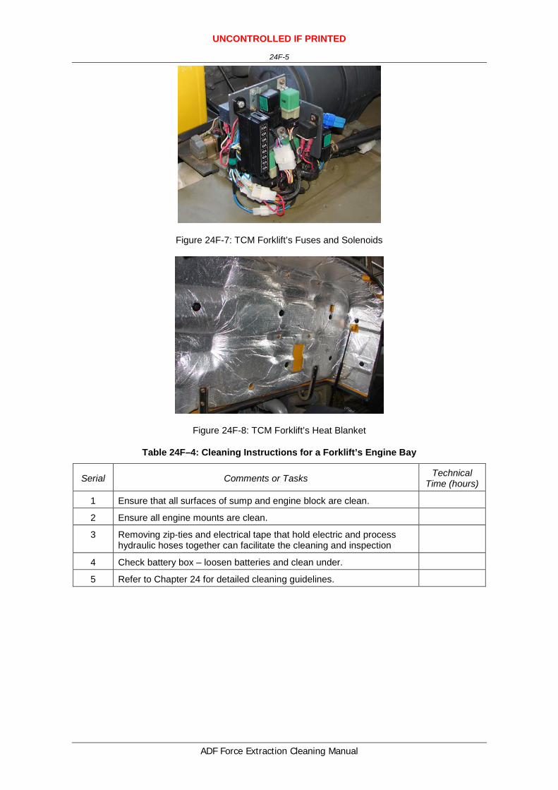
Figure 24F-7: TCM Forklift’s Fuses and Solenoids
Figure 24F-8: TCM Forklift’s Heat Blanket
Table 24F–4: Cleaning Instructions for a Forklift’s Engine Bay
Serial Comments or Tasks Technical Time (hours)
1 Ensure that all surfaces of sump and engine block are clean.
2 Ensure all engine mounts are clean.
3 Removing zip-ties and electrical tape that hold electric and process hydraulic hoses together can facilitate the cleaning and inspection
4 Check battery box – loosen batteries and clean under.
5 Refer to Chapter 24 for detailed cleaning guidelines.


UNCONTROLLED IF PRINTED
24G-1
ADF Force Extraction Cleaning Manual
ANNEX G TO CHAPTER 24
CLEANING INSTRUCTIONS – PACIFIC ATF250 25 TONNE
ROUGH TERRAIN
1. This annex provides basic and specific cleaning requirements for selected vehicles. Where there is a specific requirement or need to highlight particular problem areas detailed cleaning guides are provided as tables and figures in this annex.
2. The cleaning requirements that follow are in addition to those points for forklifts included in Chapter 24G of this publication.
External Areas
3. The cleaning instructions for the Pacific ATF250’s external areas, as illustrated in Figures 24G-1 to 24G-3, include the points detailed in Table 24G-1.
Figure 24G-1: Pacific ATF250’s External Areas

UNCONTROLLED IF PRINTED
24G-2
ADF Force Extraction Cleaning Manual
Figure 24G-2: Pacific ATF250’s Rear External Areas Drivers Side
Figure 24G-3: Pacific ATF250’s Spare Wheel Mounted
Table 24G-1: Cleaning Instructions for the Pacific ATF250’s External Areas
Serial Comments or Tasks Technical Time (hours)
1 The underside of the vehicle is to be cleaned with high-pressure water.
2 All attachments that may collect plant, seed and insect matter are to be cleaned and checked. If necessary, the attachments and covers are to be removed to facilitate cleaning.

UNCONTROLLED IF PRINTED
24G-3
ADF Force Extraction Cleaning Manual
Serial Comments or Tasks Technical Time (hours)
3 Refer to Chapter 24 for detailed cleaning guidelines.
Cabin
4. The cleaning instructions for the Forklift’s cabin, as illustrated in Figures 24G-4 and 24G-5, include the points detailed in Table 24G-2.
Figure 24G–4: Pacific ATF250’s Seat and Seat Shroud
Figure 24G–5: Pacific ATF250’s Controls and Dashboard

UNCONTROLLED IF PRINTED
24G-4
ADF Force Extraction Cleaning Manual
Table 24G–2: Cleaning Instructions for a Forklift’s Cabin
Serial Comments or Tasks Technical Time (hours)
1 Areas under the dash are difficult to clean. A vacuum and low-pressure compressed air should be used to remove dust and insect debris.
2 Remove and clean under the seat, including the rubber seat shroud.
3 Refer to Chapter 24 for detailed cleaning guidelines.
Boom and Boom Housing
5. The cleaning instructions for a Forklift’s boom and boom housing, as illustrated in Figure 24G-6, include the points detailed in Table 24-3.
Figure 24G–6: Pacific ATF250’s Boom and Boom Housing
Table 24G–3: Cleaning Instructions for a Forklift’s Boom and Boom Housing
Serial Comments or Tasks Technical Time (hours)
1 All grease is to be removed from the boom housing. This may require the use of degreaser spayed the full internal length of the boom and hot washed to remove contaminants.
2 The boom is to be extended to facilitate cleaning.
3 Refer to Chapter 24 for detailed cleaning guidelines.
Engine Bay
6. The cleaning instructions for the Pacific ATF250’s radiator, as illustrated in Figures 24G-7 to 24G-9, include the points detailed in Table 24G-4

UNCONTROLLED IF PRINTED
24G-5
ADF Force Extraction Cleaning Manual
Figure 24G–7: Pacific ATF250’s Engine Bay
Figure 24G–8: Pacific ATF250’s Batter Bay
Figure 24G–9: Pacific ATF250’s Batter Cradle
Table 24G–2: Cleaning Instructions for the Pacific ATF250’s Engine Bay
Serial Comments or Tasks Technical Time (hours)
1 The radiator cowling may need to be removed to facilitate the cleaning 0.5

UNCONTROLLED IF PRINTED
24G-6
ADF Force Extraction Cleaning Manual
Serial Comments or Tasks Technical Time (hours)
of the radiator.
2 Remove battery and clean battery box and terminals
3 Refer to Chapter 24 for detailed cleaning guidelines.
Hydraulic and Electrical Cables
7. The cleaning instructions for the Pacific ATF250’s hydraulic and electrical cable, as illustrated in Figure 24G-10, include the points detailed in Table 24G-5.
Figure 2–10: Pacific ATF250’s Hydraulic and Electrical Cables
Table 24G–5: Cleaning Instructions for the Pacific ATF250’s Hydraulic and Electrical Cables
Serial Comments or Tasks Technical Time (hours)
1 All electrical and hydraulic lines are to be separated and all grease and soil debris cleaned from in between them.
2.0
Suspension
8. The specific cleaning instructions a forklift’s suspension, as illustrated in Figures 24G-11 and 24G-12,include those points detailed in Table 24G-6.
Figure 24G–11: Pacific ATF250’s Front Suspension

UNCONTROLLED IF PRINTED
24G-7
ADF Force Extraction Cleaning Manual
Figure 24G–12: Pacific ATF250’s rear Suspension
Table 24G-6: Cleaning Instructions for the Forklift’s Suspension
Serial Comments or Tasks Technical Time (hours)
1 Ensure axles and mounts on chassis are clean and free of soil, plant and insect material.
2 Refer to Chapter 24 for detailed cleaning guidelines.


UNCONTROLLED IF PRINTED
24H-1
ADF Force Extraction Cleaning Manual
ANNEX H TO CHAPTER 24
CLEANING INSTRUCTIONS – FORKLIFT MANITOU M50-4
1. This annex provides basic and specific cleaning requirements for selected vehicles. Where there is a specific requirement or need to highlight particular problem areas detailed cleaning guides are provided as tables and figures in this annex.
2. The cleaning requirements that follow are in addition to those points for forklifts included in Chapter 24 of this publication.
External Areas
3. The cleaning instructions for the Manitou M50-4 Forklift’s external, as illustrated in Figures 24H-1 to 24H-4, include the points detailed in Table 24H-1.
Figure 24H-1: Manitou M50-4 Forklift’s External Areas

UNCONTROLLED IF PRINTED
24H-2
ADF Force Extraction Cleaning Manual
Figure 24H-2: Manitou M50-4 Forklift Rear
Figure 24H-3: Manitou M50-4 Forklift’s Battery Box
Table 24H–1: Cleaning Instructions for a Manitou M50-4 Forklift’s External Areas
Serial Comments or Tasks Technical Time (hours)
1 All attachments that may collect plant, seed and insect matter are to be removed, checked and cleaned. Once removed, all external areas of the forklift are to be cleaned clean (refer Figure 24H- 1).
2 Remove battery and clean battery box and terminals (refer Figure 24H- 2).
3 Remove air compressor and ensure housing is clear of insect and plant material. Dispose of used air cleaner element (refer Figure 24H-3).

UNCONTROLLED IF PRINTED
24H-3
ADF Force Extraction Cleaning Manual
Serial Comments or Tasks Technical Time (hours)
4 Special attention is to be paid on the mudguards which are to be cleaned with high-pressure water terminals (refer Figure 24H- 4).
5 Refer to Chapter 24 for detailed cleaning guides.
Cabin
4. The cleaning instructions for the Manitou M50-4 Forklift’s cabin, as illustrated in Figures 24H-4 and 24H-5, include the points detailed in Table 24H-2.
Figure 24H-4: Manitou M50-4 Forklift’s Cab Front
Figure 24H-5: Manitou M50-4 Forklift’s Dash
Table 24H-2: Cleaning Instructions for a Manitou M50-4 Forklift’s Cabin
Serial Comments or Tasks Technical Time (hours)
1 Remove and clean all door rubbers, internal door panelling and clean all windowsills (refer Figure 24H- 5 and 24H-6).
2 Areas under the dash are difficult to clean. A vacuum and low-pressure compressed air should be used to remove dust and insect debris (refer

UNCONTROLLED IF PRINTED
24H-4
ADF Force Extraction Cleaning Manual
Serial Comments or Tasks Technical Time (hours)
Figure 24H- 7).
3 All air-conditioning vents must be internally cleaned. Access will be required for inspection (refer Figure 24H- 7 and 24H-8).
4. Remove and clean under the seat, including the rubber seat shroud (refer Figure 24H-9).
5. Refer to Chapter 24 for detailed cleaning guides.
Hoist
5. The cleaning instructions for a Manitou M50-4 Forklift’s hoist, as illustrated in Figure 24H-6, include those points detailed in Table 24H-3.
Figure 24H-6: Manitou M50-4 Forklift’s Hoist
Table 24–3: Cleaning Instructions for a Manitou M50-4 Forklift’s Hoist
Serial Comments or Tasks Technical Time (hours)
1 The boom is to be extended to facilitate cleaning (refer Figure 24H-20).
2 All hydraulic rams are to be extended to facilitate cleaning. Hydraulic lines and cabling are to be wiped clean, conduit is to be flushed clean with a high-pressure water cleaner (refer figures 24H-31 to 24H-46).
3 All grease is to be removed from the boom housing. This may require the use of degreaser spayed the full internal length of the boom and hot washed to remove contaminants.
4 Refer to Chapter 24 for detailed cleaning guides.

UNCONTROLLED IF PRINTED
24H-5
ADF Force Extraction Cleaning Manual
Hydraulic and Electrical Cables
6. The cleaning instructions for the Manitou M50-4 Forklift’s hydraulic and electrical, as illustrated in Figure 24H-7, include those points detailed in Table 24H-4.
Figure 24H-7: Manitou M50-4 Forklift’s Hydraulic Hoses
Table 24–4: Cleaning Instructions for the a Manitou M50-4 Forklift’s Hydraulic and Electrical Cables
Serial Comments or Tasks Technical Time (hours)
1 All electrical and hydraulic lines are to be separated and all grease and soil debris cleaned from in between them (refer Figure 24H-21).
Engine Bay
7. The cleaning instructions for a Manitou M50-4 Forklift’s engine, as illustrated in Figure 24H-8 to 24H-10, include the points detailed in Table 24H-5.
Figure 24H-8: Manitou M50-4 Forklift’s Engine Bay

UNCONTROLLED IF PRINTED
24H-6
ADF Force Extraction Cleaning Manual
Figure 24H-9: Manitou M50-4 Forklift’s Air Filter
Figure 24H-50: Manitou M50-4 Forklift’s Radiator
Table 24–5: Cleaning Instructions for a Manitou M50-4 Forklift’s Engine Bay
Serial Comments or Tasks Technical Time (hours)
1 Remove air-filter pre-cleaner cover and clean (refer 24H-18).
2 Remove air-filter and clean with air.
3 The radiator cowling may need to be removed to facilitate the cleaning of the radiator (refer 24H-19).
4 Flush radiator and oil cooler from both sides to verify fin/core cleanliness.
5 Loosen radiator shroud to let any loose debris fall through after flushing.
6 Check either side of radiator for vertical hollow support structures. Flush to verify internal cleanliness if present.
7 Refer to Chapter 24 for detailed cleaning guides.

UNCONTROLLED IF PRINTED
24I-1
ADF Force Extraction Cleaning Manual
ANNEX I TO CHAPTER 24
CLEANING INSTRUCTIONS – CASE W36 FORKLIFT
1. This annex provides basic and specific cleaning requirements for selected vehicles. Where there is a specific requirement or need to highlight particular problem areas detailed cleaning guides are provided as tables and figures in this annex.
2. The cleaning requirements that follow are in addition to those points for forklifts included in Chapter 24I of this publication.
External Areas
3. The cleaning instructions for the Case Forklift’s external areas, as illustrated in Figure 24I-1, include the points detailed in Table 24I-1.
Figure 24I-1: Case Forklift’s External Areas
Table 24I-1: Cleaning Instructions for the Case Forklift’s External Areas
Serial Comments or Tasks Technical Time (hours)
1 Covers and attachments are to be cleaned and, if necessary, removed to facilitate cleaning.
2 Refer to Chapter 24 for detailed cleaning guidelines.
Cabin Area
4. The cleaning instructions for the Case Forklift’s cabin, as illustrated in Figures 24I-2 and 24I-3, include the points detailed in Table 24I-2.

UNCONTROLLED IF PRINTED
24I-2
ADF Force Extraction Cleaning Manual
Figure 24I–2: Case Forklift’s Cabin
Figure 24I–3: Case Forklift’s Seat
Table 24I–2: Cleaning Instructions for a Case Forklift’s Cabin
Serial Comments or Tasks Technical Time (hours)
1 Areas under the dash are difficult to clean. A vacuum and low-pressure compressed air should be used to remove dust and insect debris.
2 Remove and clean under the seat, including the rubber seat shroud.
3 Refer to Chapter 24 for detailed cleaning guidelines.
Boom Housing
5. The cleaning instructions for the Case Forklift’s boom housing, as illustrated in Figures 24I-4 and 24I-5, include the points detailed in Table 24I-3.

UNCONTROLLED IF PRINTED
24I-3
ADF Force Extraction Cleaning Manual
Figure 24I-4: Case Forklift’s Boom and Forks
Figure 24I-5: Case Forklift’s Main Rams
Table 24I–2: Cleaning Instructions for the Case Forklift’s Boom Housing
Serial Comments or Tasks Technical Time (hours)
1 All grease is to be removed from the boom housing. This may require the use of degreaser spayed the full internal length of the boom and hot washed to remove contaminants.
2 Refer to Chapter 24 for detailed cleaning guidelines.
Engine Bay
6. The cleaning instructions for the Case Forklift’s engine bay, as illustrated in Figure 24I-6, include the point detailed in Table 24I-4

UNCONTROLLED IF PRINTED
24I-4
ADF Force Extraction Cleaning Manual
Figure 24I–6: Case’s Engine
Table 24I–3: Cleaning Instructions for the Case’s Engine Bay
Serial Comments or Tasks Technical Time (hours)
1 The radiator cowling may need to be removed to facilitate the cleaning of the radiator.
0.5
2 Refer to Chapter 24 for detailed cleaning guidelines.

UNCONTROLLED IF PRINTED
24J-1
ADF Force Extraction Cleaning Manual
ANNEX J TO CHAPTER 24
CLEANING INSTRUCTIONS – FORKLIFT MANITOU MT932
1. This annex provides basic and specific cleaning requirements for selected vehicles. Where there is a specific requirement or need to highlight particular problem areas detailed cleaning guides are provided as tables and figures in this annex.
2. The cleaning requirements that follow are in addition to those points for forklifts included in Chapter 24 of this publication.
External Areas
3. The cleaning instructions for the Manitou MT932 Forklift’s external, as illustrated in Figures 24J-1 to 24J-3, include the points detailed in Table 24J-1.
Figure 24J-1: Manitou MT932 Forklift’s External Areas

UNCONTROLLED IF PRINTED
24J-2
ADF Force Extraction Cleaning Manual
Figure 24J-2: Manitou MT932 Forklift’s Rear
Figure 24J-3: Manitou MT932 Forklift’s Battery Box
Table 24H–1: Cleaning Instructions for a Manitou MT932 Forklift’s External Areas
Serial Comments or Tasks Technical Time (hours)
1 All attachments that may collect plant, seed and insect matter are to be removed, checked and cleaned. Once removed, all external areas of the forklift are to be cleaned clean (refer Figure 24J- 1).
2 Remove battery and clean battery box and terminals (refer Figure 24J- 3). The battery box is located under a cover plate on the lower right-hand side of the engine bay.

UNCONTROLLED IF PRINTED
24J-3
ADF Force Extraction Cleaning Manual
Serial Comments or Tasks Technical Time (hours)
3 Special attention is to be paid on the mudguards which are to be cleaned with high-pressure water terminals.
4 Refer to Chapter 24 for detailed cleaning guides.
Cabin
4. The cleaning instructions for the Manitou MT932 Forklift’s cabin, as illustrated in Figures 24J-4 and 24J-6, include the points detailed in Table 24J-2.
Figure 24J-4: Manitou MT932 Forklift’s Cab Front
Figure 24J-5: Manitou MT932 Forklift’s Dash
UNCONTROLLED IF PRINTED
24J-4
ADF Force Extraction Cleaning Manual
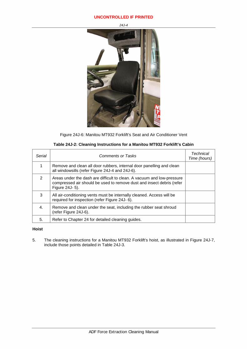
Figure 24J-6: Manitou MT932 Forklift’s Seat and Air Conditioner Vent
Table 24J-2: Cleaning Instructions for a Manitou MT932 Forklift’s Cabin
Serial Comments or Tasks Technical Time (hours)
1 Remove and clean all door rubbers, internal door panelling and clean all windowsills (refer Figure 24J-4 and 24J-6).
2 Areas under the dash are difficult to clean. A vacuum and low-pressure compressed air should be used to remove dust and insect debris (refer Figure 24J- 5).
3 All air-conditioning vents must be internally cleaned. Access will be required for inspection (refer Figure 24J- 6).
4. Remove and clean under the seat, including the rubber seat shroud (refer Figure 24J-6).
5. Refer to Chapter 24 for detailed cleaning guides.
Hoist
5. The cleaning instructions for a Manitou MT932 Forklift’s hoist, as illustrated in Figure 24J-7, include those points detailed in Table 24J-3.

UNCONTROLLED IF PRINTED
24J-5
ADF Force Extraction Cleaning Manual
Figure 24J-7: Manitou MT932 Forklift’s Hoist
Table 24–3: Cleaning Instructions for a Manitou MT932 Forklift’s Hoist
Serial Comments or Tasks Technical Time (hours)
1 The boom is to be extended to facilitate cleaning.
2 All hydraulic rams are to be extended to facilitate cleaning. Hydraulic lines and cabling are to be wiped clean, conduit is to be flushed clean with a high-pressure water cleaner.
3 All grease is to be removed from the boom housing. This may require the use of degreaser spayed the full internal length of the boom and hot washed to remove contaminants.
4 Refer to Chapter 24 for detailed cleaning guides.
Engine Bay
6. The cleaning instructions for a Manitou MT932 Forklift’s engine, as illustrated in Figures 24J-8 to 24J-10, include the points detailed in Table 24J-4.

UNCONTROLLED IF PRINTED
24J-6
ADF Force Extraction Cleaning Manual
Figure 24J-8: Manitou MT932 Forklift’s Engine Bay
Figure 24J-9: Manitou MT932 Forklift’s Air Filter
Figure 24J-10: Manitou MT932 Forklift’s Radiator & Heat Exchanger
UNCONTROLLED IF PRINTED
24J-7
ADF Force Extraction Cleaning Manual
Table 24-4: Cleaning Instructions for a Manitou MT932 Forklift’s Engine Bay
Serial Comments or Tasks Technical Time (hours)
1 Remove air-filter pre-cleaner cover and clean (refer 24J-9).
2 Remove air-filter and clean with air.
3 The radiator cowling may need to be removed to facilitate the cleaning of the radiator (refer 24J-10).
4 Flush radiator and oil cooler from both sides to verify fin/core cleanliness.
5 Loosen radiator shroud to let any loose debris fall through after flushing.
6 Check either side of radiator for vertical hollow support structures. Flush to verify internal cleanliness if present.
7 Refer to Chapter 24 for detailed cleaning guides.
Suspension
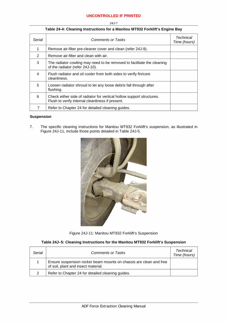
7. The specific cleaning instructions for Manitou MT932 Forklift’s suspension, as illustrated in Figure 24J-11, include those points detailed in Table 24J-5.
Figure 24J-11: Manitou MT932 Forklift’s Suspension
Table 24J–5: Cleaning Instructions for the Manitou MT932 Forklift’s Suspension
Serial Comments or Tasks Technical Time (hours)
1 Ensure suspension rocker beam mounts on chassis are clean and free of soil, plant and insect material.
2 Refer to Chapter 24 for detailed cleaning guides.


UNCONTROLLED IF PRINTED
24K-1
ADF Force Extraction Cleaning Manual
ANNEX K TO CHAPTER 24
CLEANING INSTRUCTIONS – FORKLIFT MANITOU MHT 1060L
TURBO
1. This annex provides basic and specific cleaning requirements for selected vehicles. Where there is a specific requirement or need to highlight particular problem areas detailed cleaning guides are provided as tables and figures in this annex.
2. The cleaning requirements that follow are in addition to those points for forklifts included in Chapter 24 of this publication.
External Areas
3. The cleaning instructions for the Manitou MHT 1060L Turbo Forklift’s external, as illustrated in Figures 24K-1 to 24K-3, include the points detailed in Table 24K-1.
Figure 24K-1: Manitou MHT 1060L Turbo Forklift’s External Areas

UNCONTROLLED IF PRINTED
24K-2
ADF Force Extraction Cleaning Manual
Figure 24K-2: Manitou MHT 1060L Turbo Forklift’s Rear and Tail Lights
Figure 24K-3: Manitou MHT 1060L Turbo Forklift’s Battery Box
Figure 24K-4: Manitou MHT 1060L Turbo Forklift’s Compressor

UNCONTROLLED IF PRINTED
24K-3
ADF Force Extraction Cleaning Manual
Table 24H–1: Cleaning Instructions for a Manitou MHT 1060L Turbo Forklift’s External Areas
Serial Comments or Tasks Technical Time (hours)
1 All attachments that may collect plant, seed and insect matter are to be removed, checked and cleaned. Once removed, all external areas of the forklift are to be cleaned clean (refer Figure 24K- 1).
2 Remove battery and clean battery box and terminals (refer Figure 24K- 3). The battery box is located under a cover plate on the lower right-hand side of the engine bay.
3 Special attention is to be paid on the mudguards which are to be cleaned with high-pressure water terminals.
4 Refer to Chapter 24 for detailed cleaning guides.
Cabin
4. The cleaning instructions for the Manitou MHT 1060L Turbo Forklift’s cabin, as illustrated in Figures 24K-5 and 24K-10, include the points detailed in Table 24K-2.
Figure 24K-5: Manitou MHT 1060L Turbo Forklift’s Cab Front
Figure 24K-6: Manitou MHT 1060L Turbo Forklift’s Dash

UNCONTROLLED IF PRINTED
24K-4
ADF Force Extraction Cleaning Manual
Figure 24K-7: Manitou MHT 1060L Turbo Forklift’s Under Dash
Figure 24K-8: Manitou MHT 1060L Turbo Forklift’s Seat
Figure 24K-9: Manitou MHT 1060L Turbo Forklift’s Air Conditioner Vents

UNCONTROLLED IF PRINTED
24K-5
ADF Force Extraction Cleaning Manual
Figure 24K-10: Manitou MHT 1060L Turbo Forklift’s Ceiling
Table 24K-2: Cleaning Instructions for a Manitou MHT 1060L Turbo Forklift’s Cabin
Serial Comments or Tasks Technical Time (hours)
1 Remove and clean all door rubbers, internal door panelling and clean all windowsills (refer Figure 24K-4 and 24K-6).
2 Areas under the dash are difficult to clean. A vacuum and low-pressure compressed air should be used to remove dust and insect debris (refer Figure 24K- 5).
3 All air-conditioning vents must be internally cleaned. Access will be required for inspection (refer Figure 24K- 6).
4. Remove and clean under the seat, including the rubber seat shroud (refer Figure 24K-6).
5. Refer to Chapter 24 for detailed cleaning guides.
Boom
5. The cleaning instructions for a Manitou MHT 1060L Turbo Forklift’s boom, as illustrated in Figures 24K-11 and 24K-12, include those points detailed in Table 24K-3.

UNCONTROLLED IF PRINTED
24K-6
ADF Force Extraction Cleaning Manual
Figure 24K-11: Manitou MHT 1060L Turbo Forklift’s Hoist
Figure 24K-12: Manitou MHT 1060L TURBO Forklift’s Turbo Hoist Hydraulics
Table 24–3: Cleaning Instructions for a Manitou MHT 1060L Turbo Forklift’s Boom
Serial Comments or Tasks Technical Time (hours)
1 The boom is to be extended to facilitate cleaning.
2 All hydraulic rams are to be extended to facilitate cleaning. Hydraulic lines and cabling are to be wiped clean, conduit is to be flushed clean with a high-pressure water cleaner.
3 All grease is to be removed from the boom housing. This may require the use of degreaser spayed the full internal length of the boom and hot washed to remove contaminants.

UNCONTROLLED IF PRINTED
24K-7
ADF Force Extraction Cleaning Manual
Serial Comments or Tasks Technical Time (hours)
4 Refer to Chapter 24 for detailed cleaning guides.
5 All electrical and hydraulic lines are to be separated and all grease and soil debris cleaned from in between them.
Engine Bay
6. The cleaning instructions for a Manitou MHT 1060L Turbo Forklift’s engine, as illustrated in Figure 24K-13 to 24K-17, include the points detailed in Table 24K-4.
Figure 24K-13: Manitou MHT 1060L Turbo Forklift’s Engine Bay
Figure 24K-14: Manitou MHT 1060L Turbo Forklift’s Air Filter

UNCONTROLLED IF PRINTED
24K-8
ADF Force Extraction Cleaning Manual
Figure 24K-15: Manitou MHT 1060L Turbo Forklift’s Radiator
Figure 24K-16: Manitou MHT 1060L Turbo Forklift’s External Radiator Cover
Figure 24K-17: Manitou MHT 1060L Turbo Forklift’s Exhaust

UNCONTROLLED IF PRINTED
24K-9
ADF Force Extraction Cleaning Manual
Table 24-4: Cleaning Instructions for a Manitou MHT 1060L Turbo Forklift’s Engine Bay
Serial Comments or Tasks Technical Time (hours)
1 Remove air-filter pre-cleaner cover and clean (refer 24K-9).
2 Remove air-filter and clean with air.
3 The radiator cowling may need to be removed to facilitate the cleaning of the radiator (refer 24K-10).
4 Flush radiator and oil cooler from both sides to verify fin/core cleanliness.
5 Loosen radiator shroud to let any loose debris fall through after flushing.
6 Check either side of radiator for vertical hollow support structures. Flush to verify internal cleanliness if present.
7 Refer to Chapter 24 for detailed cleaning guides.
Suspension
7. The specific cleaning instructions for Manitou MHT 1060L Turbo Forklift’s suspension, as illustrated in Figure 24K-18, include those points detailed in Table 24K-5.
Figure 24K-18: Manitou MHT 1060L Turbo Forklift’s Rear Suspension
Table 24K–5: Cleaning Instructions for the Manitou MHT 1060L Turbo Forklift’s Suspension
Serial Comments or Tasks Technical Time (hours)
1 Ensure suspension rocker beam mounts on chassis are clean and free of soil, plant and insect material.
2 Refer to Chapter 24 for detailed cleaning guides.


UNCONTROLLED IF PRINTED
24L-1
ADF Force Extraction Cleaning Manual
ANNEX L TO CHAPTER 24
CLEANING INSTRUCTIONS – FORKLIFT HITACHI LX120
1. This annex provides basic and specific cleaning requirements for selected vehicles. Where there is a specific requirement or need to highlight particular problem areas detailed cleaning guides are provided as tables and figures in this Annex.
2. The cleaning requirements that follow are in addition to those points for forklifts included in Chapter 24 of this publication.
3. For the cleaning instructions for the Hitachi LX120 forklift, refer to Chapter 17 - Wheel Loader Hitachi LX120.
Figure 24L-1: Forklift Hitachi LX120

UNCONTROLLED IF PRINTED
24M-1
ADF Force Extraction Cleaning Manual
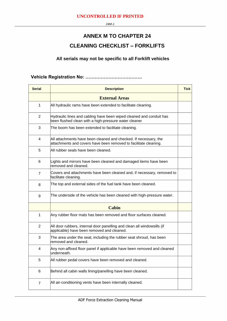
ANNEX M TO CHAPTER 24
CLEANING CHECKLIST – FORKLIFTS
All serials may not be specific to all Forklift vehicles
Vehicle Registration No: ……………………………….
Serial
Description
Tick
External Areas
1 All hydraulic rams have been extended to facilitate cleaning.
2 Hydraulic lines and cabling have been wiped cleaned and conduit has been flushed clean with a high-pressure water cleaner
3 The boom has been extended to facilitate cleaning.
4 All attachments have been cleaned and checked. If necessary, the attachments and covers have been removed to facilitate cleaning.
5 All rubber seals have been cleaned.
6 Lights and mirrors have been cleaned and damaged items have been removed and cleaned.
7 Covers and attachments have been cleaned and, if necessary, removed to facilitate cleaning.
8 The top and external sides of the fuel tank have been cleaned.
9 The underside of the vehicle has been cleaned with high-pressure water.
Cabin
1 Any rubber floor mats has been removed and floor surfaces cleaned.
2 All door rubbers, internal door panelling and clean all windowsills (if applicable) have been removed and cleaned.
3 The area under the seat, including the rubber seat shroud, has been removed and cleaned.
4 Any non-affixed floor panel if applicable have been removed and cleaned underneath.
5 All rubber pedal covers have been removed and cleaned.
6 Behind all cabin walls lining/panelling have been cleaned.
7 All air-conditioning vents have been internally cleaned.

UNCONTROLLED IF PRINTED
24M-2
ADF Force Extraction Cleaning Manual
Serial
Description
Tick
8 The inside of all joystick controls have been cleaned.
9 The cleanliness of the cabin roof, both inside and out has been checked.
10 The ladder to cabin (if fitted) and under each footstep has been cleaned.
11 All light covers have been cleaned.
12 The windscreen reservoir has been emptied (if fitted).
13 A check for a false floor under the cabin has been conducted and removed for cleaning, if applicable.
14 The dash has been vacuumed and low-pressure compressed air has been used to remove dust and insect debris.
15 Soil debris under and behind the cabin rail removed.
Belly Plate
1 The belly plate has been extensive flushed with a flexible nozzle through the sides and bottom access hole.
Boom and Boom Housing
1 All grease has been removed from the boom housing.
2 The boom has been extended to facilitate cleaning.
3 All hydraulic rams have been extended to facilitate cleaning
4 . Hydraulic lines and cabling have been wiped clean.
5 Conduit has been flushed clean with a high-pressure water cleaner. If necessary, the conduit has been removed.
Engine Bay
1 The air-filter pre-cleaner cover has been removed and cleaned.
2 The air-filter has been removed and cleaned with air.
3 The inside fan-belt flywheels has been cleaned.
4 All surfaces of the engine block including between tappet covers has been checked.
5 All belly plates have been removed if applicable and cleaned.
6 All non-affixed engine covers have been removed to allow access for cleaning and inspection.

UNCONTROLLED IF PRINTED
24M-3
ADF Force Extraction Cleaning Manual
Serial
Description
Tick
7 All engine cover rubbers have been removed for cleaning and inspection.
8 The engine housing has been checked for open-ended or spot-welded hollow support framework and flushed to verify cleanliness.
9 The radiator cowling has been removed to facilitate the cleaning of the radiator.
10 The radiator and oil cooler has been flushed from both sides to verify fin/core cleanliness.
11 The radiator shroud has been loosened to let any loose debris fall through after flushing.
12 Either side of radiator has been checked for vertical hollow support structures and flushed to verify internal cleanliness if present.
13 All wiring harnesses has been checked for internal cleanliness.
14 All hydraulic looming has been checked for cleanliness.
15 All engine mounts are clean.
16 All surfaces of sump and engine block are clean.
17 All water reservoirs have been emptied (excluding radiator).
18 All contaminated grease from universal joints has been removed.
19 All light cover internal areas have been cleaned.
Reduction Hubs
1 Soil on the top of the reduction hubs removed.
Hydraulic and Electrical Cables
1 All electrical and hydraulic lines have been separated and all grease and soil debris cleaned from in between them.
2 Zip-ties and electrical tape that hold electric and process hydraulic hoses have been removed to facilitate the cleaning and inspection
Drive Shaft
1 The reduction hub/drive shaft has been rotated during the cleaning process to ensure all areas are cleaned.
2 Hydraulic lines have been separated to facilitate cleaning. Where necessary, cable ties have been removed to ensure all debris is removed from between the cables.
Other High Risk Areas
1 The battery box has been cleaned under after the batteries have been loosened

UNCONTROLLED IF PRINTED
24M-4
ADF Force Extraction Cleaning Manual
Serial
Description
Tick
2 All surfaces of oil tank have been cleaned.
3 All surfaces of fuel cell have been cleaned.
4 The internal of all light covers & cavities behind have been cleaned.
Tyres (New, Old and Spares)
1 All tyres have been washed and scrubbed to remove all BRM.
2 Cracked and perished tyres have been subject to disposal.
3 All tyres have been treated with an approved residual insecticide after cleaning.
4 Fitted tyres that are damaged have been replaced with new tyres.
5 Used and fitted tyres on rims have been individually verified that the tyres are on rims, inflated with beading sealed and that the tyres are clean, free of water and other BRM.
6 Tyres that are not fitted to rims have been stored in such a manner that water cannot collect inside the tyre. Tyres not fitted on rims will require fumigation on return to Australia.
7 The consignment contains a maximum of 8 tyres and is to be imported with an accompanying vehicle
or
The consignment contains more than a maximum of 8 tyres and will not be imported with an accompanying vehicle.
(Delete whichever is not applicable)
Signed ………………………………………. Date: ………………….
Name: ………………………………………