
Chapter 23: Geometric Optics - SRJCsrjcstaff.santarosa.edu/~lwillia2/41/41ch23_s14.pdfDispersion...
112
Chapter 23: Geometric Optics
Transcript of Chapter 23: Geometric Optics - SRJCsrjcstaff.santarosa.edu/~lwillia2/41/41ch23_s14.pdfDispersion...
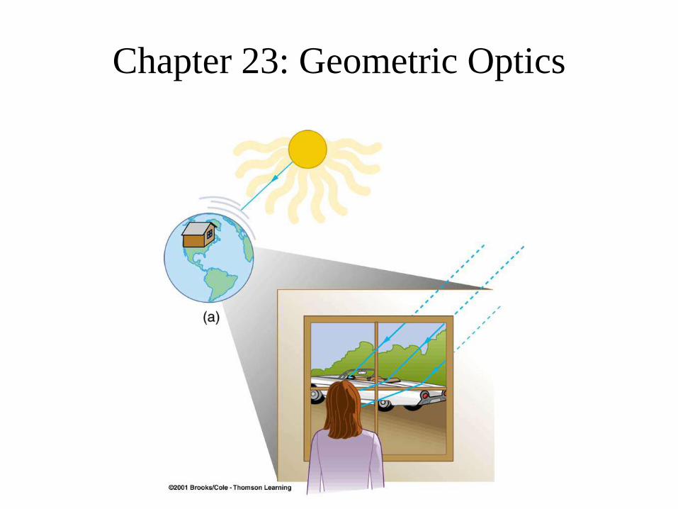
Chapter 23: Geometric Optics

Review Basic Geometry!
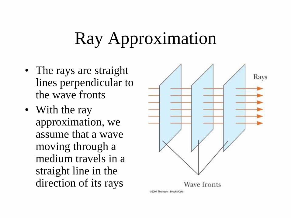
Ray Approximation
• The rays are straight lines perpendicular to the wave fronts
• With the ray approximation, we assume that a wave moving through a medium travels in a straight line in the direction of its rays
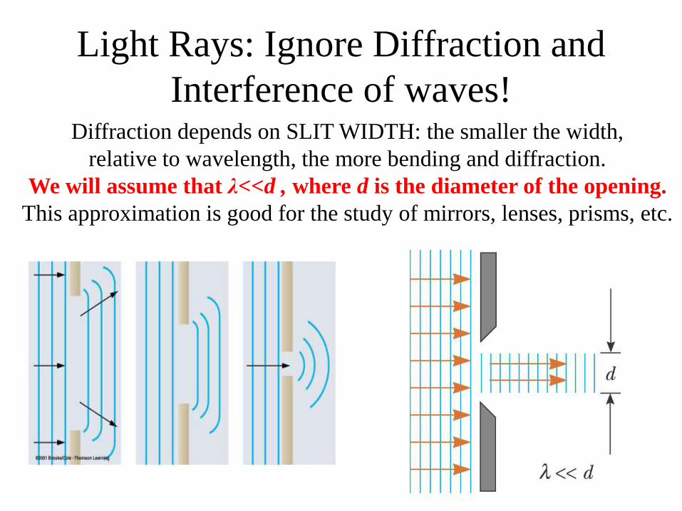
Diffraction depends on SLIT WIDTH: the smaller the width,
relative to wavelength, the more bending and diffraction.
We will assume that λ<<d , where d is the diameter of the opening.
This approximation is good for the study of mirrors, lenses, prisms, etc.
Light Rays: Ignore Diffraction and
Interference of waves!
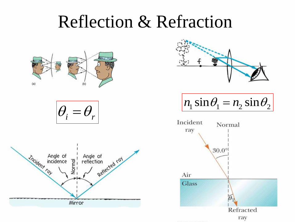
Reflection & Refraction
i r 1 1 2 2sin sinn n

Following the Reflected and
Refracted Rays •Ray is the incident ray.
•Ray is the reflected ray.
•Ray is refracted into the lucite.
•Ray is internally reflected in the lucite.
•Ray is refracted as it enters the air from the lucite. Section 35.5
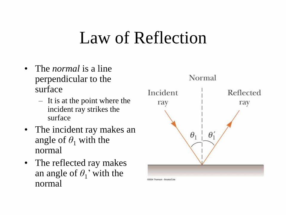
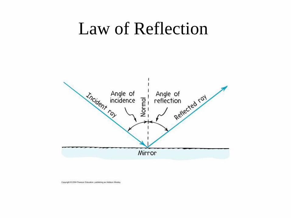
Law of Reflection
• The normal is a line perpendicular to the surface
– It is at the point where the incident ray strikes the surface
• The incident ray makes an angle of θ1 with the normal
• The reflected ray makes an angle of θ1’ with the normal
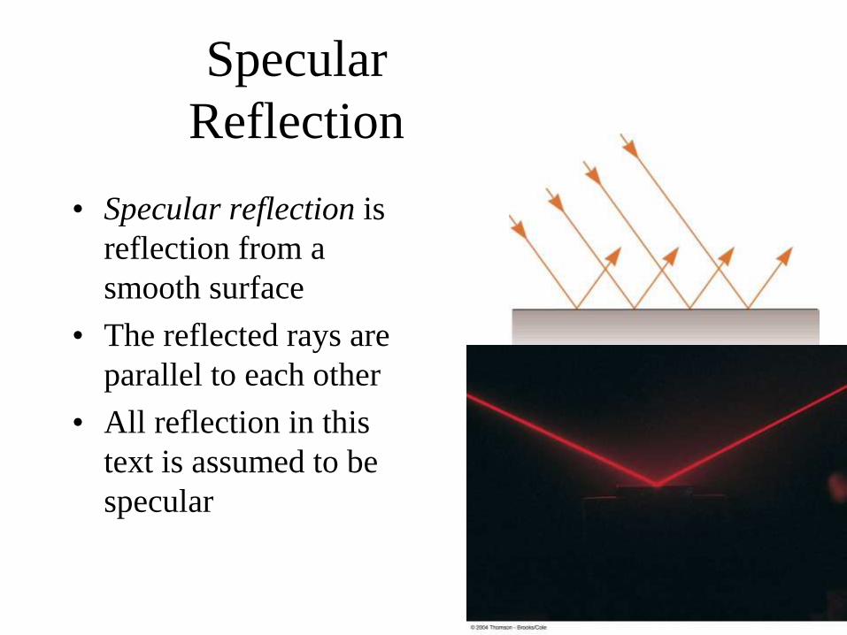
Specular
Reflection
• Specular reflection is
reflection from a
smooth surface
• The reflected rays are
parallel to each other
• All reflection in this
text is assumed to be
specular
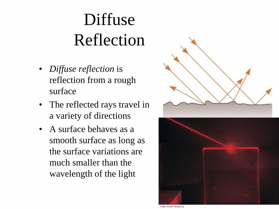
Diffuse
Reflection
• Diffuse reflection is
reflection from a rough
surface
• The reflected rays travel in
a variety of directions
• A surface behaves as a
smooth surface as long as
the surface variations are
much smaller than the
wavelength of the light
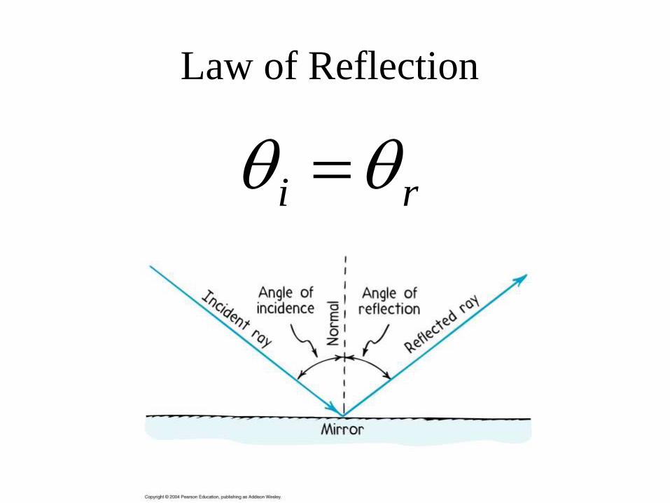
Law of Reflection
i r
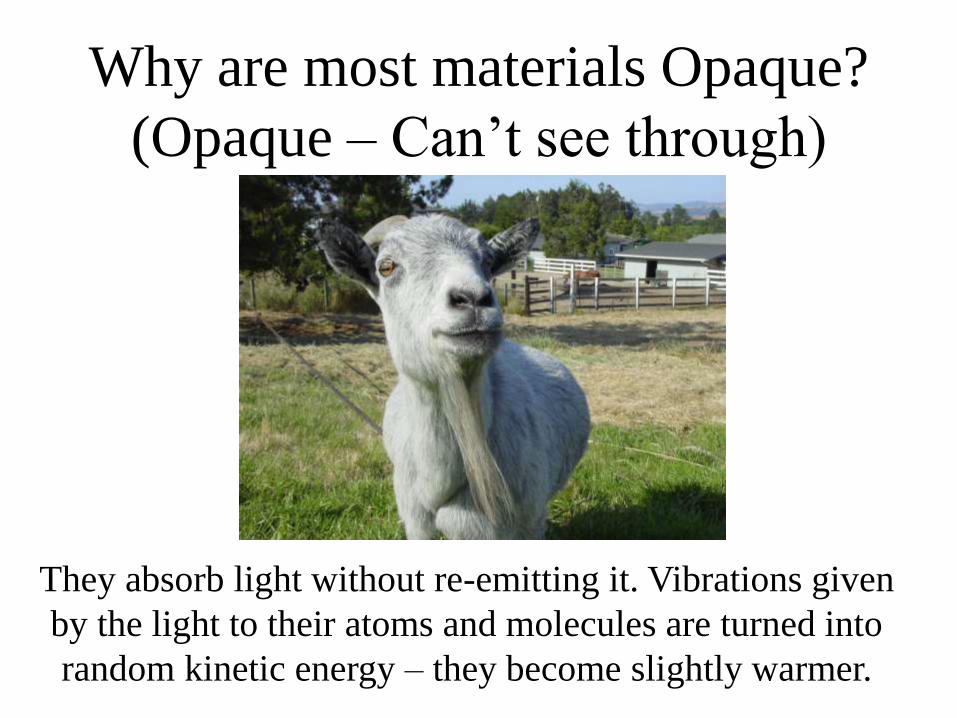
Why are most materials Opaque?
(Opaque – Can’t see through)
They absorb light without re-emitting it. Vibrations given
by the light to their atoms and molecules are turned into
random kinetic energy – they become slightly warmer.
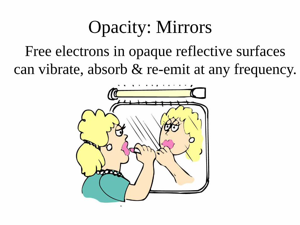
Opacity: Mirrors
Free electrons in opaque reflective surfaces
can vibrate, absorb & re-emit at any frequency.
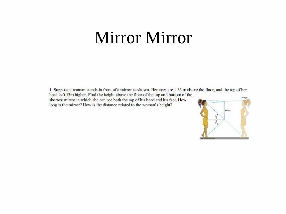
Mirror Mirror
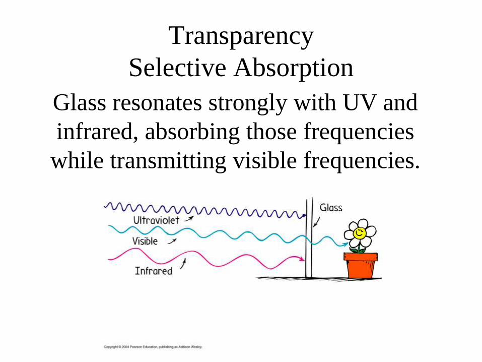
Transparency
Selective Absorption
Glass resonates strongly with UV and
infrared, absorbing those frequencies
while transmitting visible frequencies.

Refraction:
Bending Light into Focus
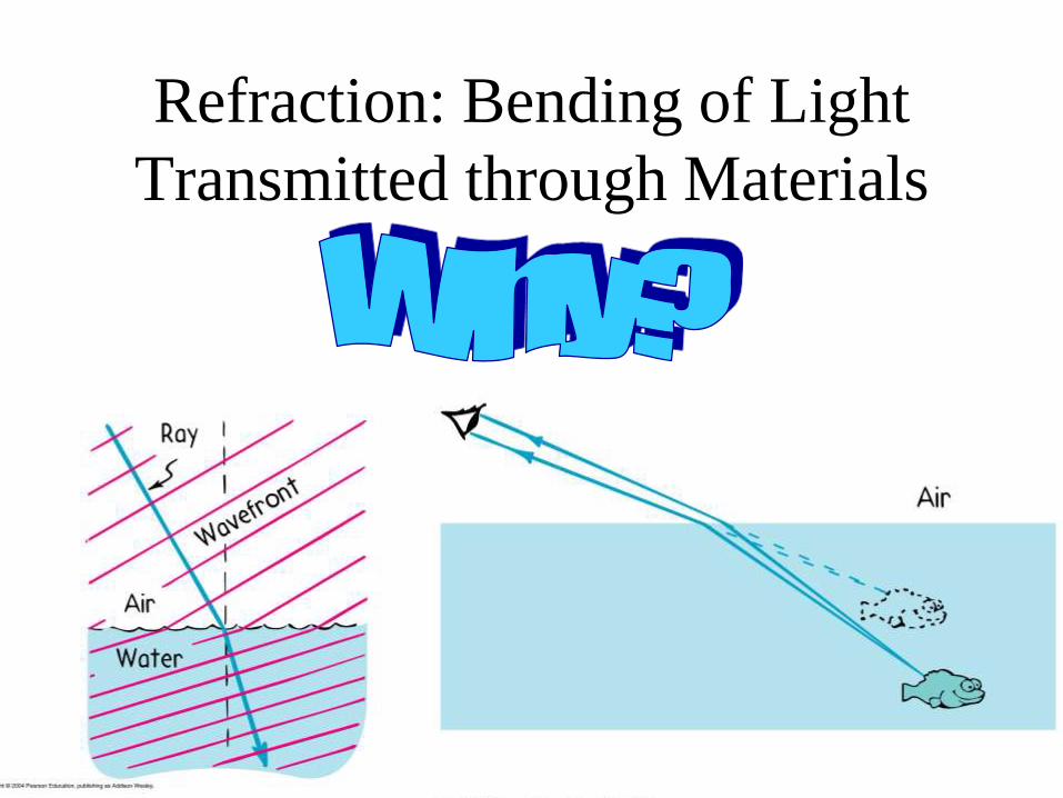
Refraction: Bending of Light
Transmitted through Materials
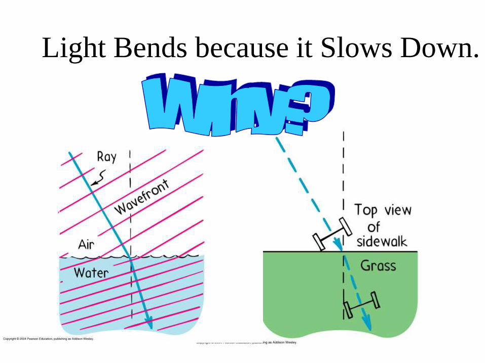
Light Bends because it Slows Down.

Atoms are Optical Tuning Forks
Light slows down as it travels through
glass because it takes time to be
absorbed and re-emitted.
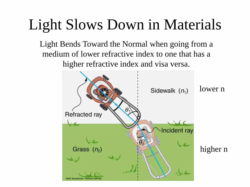
Light Slows Down in Materials Light Bends Toward the Normal when going from a
medium of lower refractive index to one that has a
higher refractive index and visa versa.
lower n
higher n
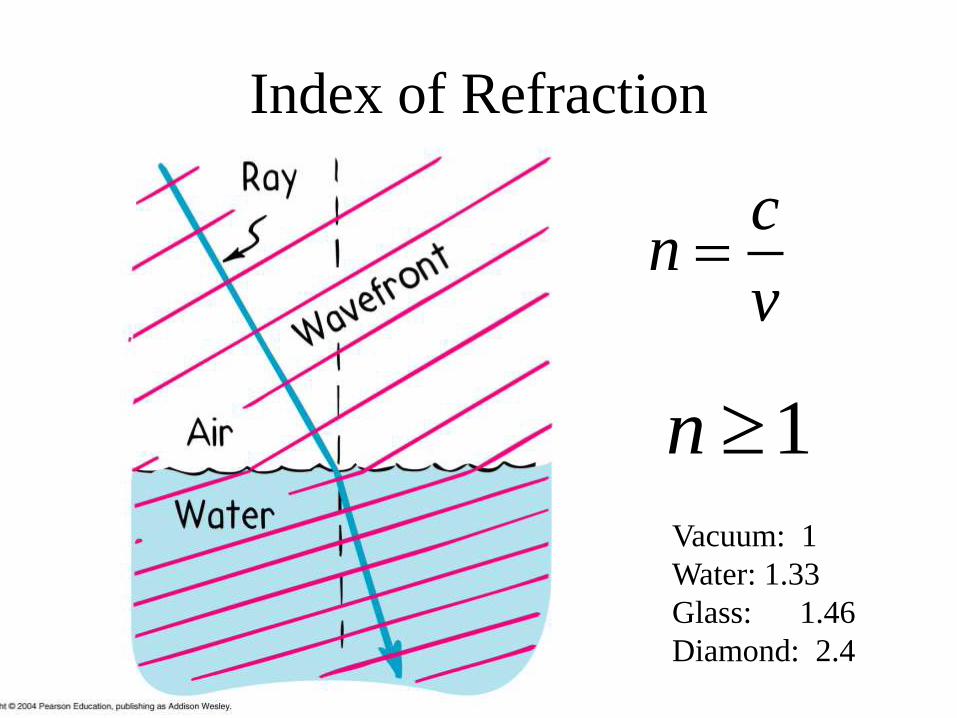
Index of Refraction
cn
v
Vacuum: 1
Water: 1.33
Glass: 1.46
Diamond: 2.4
1n
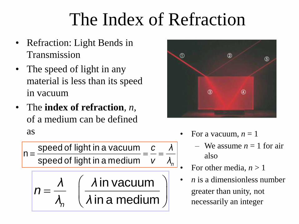
The Index of Refraction • Refraction: Light Bends in
Transmission
• The speed of light in any
material is less than its speed
in vacuum
• The index of refraction, n,
of a medium can be defined
as
speed of light in a vacuumn
speed of light in a medium n
c λ
v λ
in vacuum
in a mediumn
λ λn
λ λ
• For a vacuum, n = 1
– We assume n = 1 for air
also
• For other media, n > 1
• n is a dimensionless number
greater than unity, not
necessarily an integer
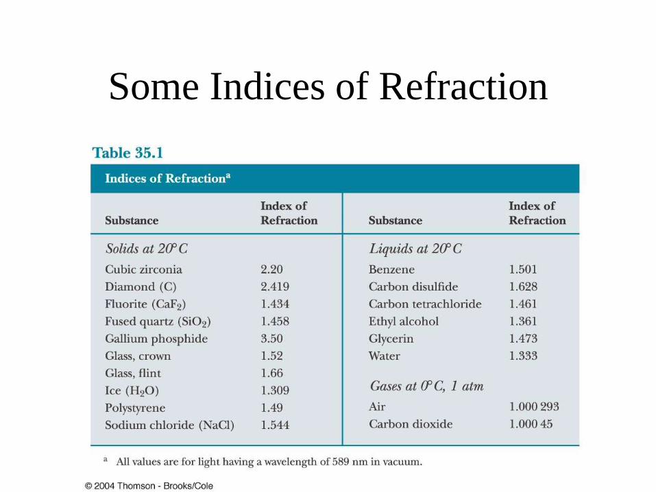
Some Indices of Refraction
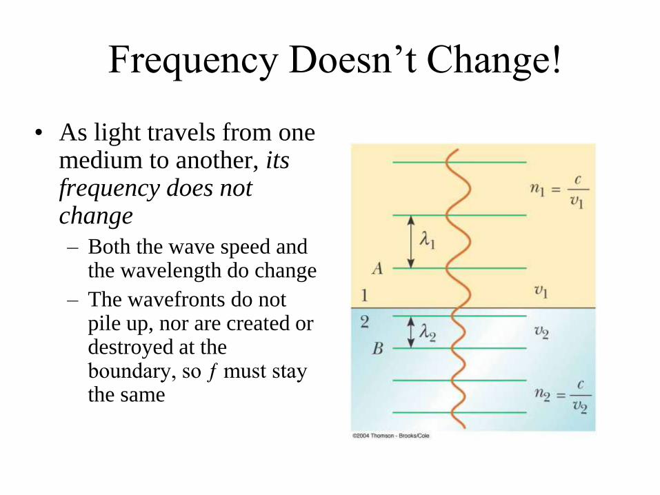
Frequency Doesn’t Change!
• As light travels from one medium to another, its frequency does not change
– Both the wave speed and the wavelength do change
– The wavefronts do not pile up, nor are created or destroyed at the boundary, so ƒ must stay the same
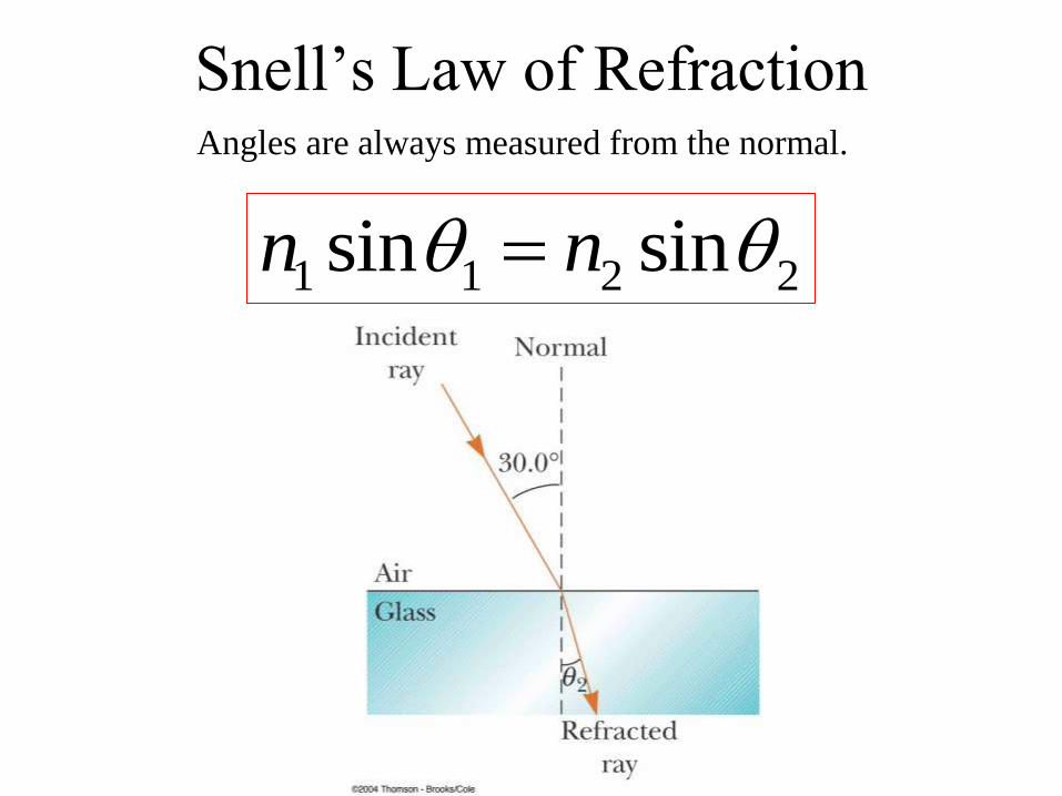
Snell’s Law of Refraction
1 1 2 2sin sinn n
Angles are always measured from the normal.
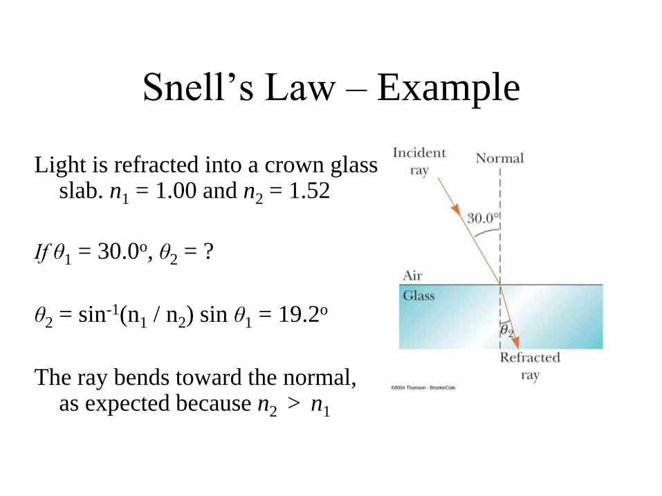
Snell’s Law – Example
Light is refracted into a crown glass slab. n1 = 1.00 and n2 = 1.52
If θ1 = 30.0o, θ2 = ?
θ2 = sin-1(n1 / n2) sin θ1 = 19.2o
The ray bends toward the normal, as expected because n2 > n1
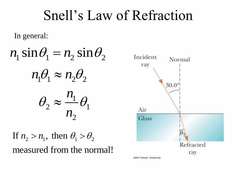
Snell’s Law of Refraction
1 1 2 2sin sinn n
In general:
1 1 2 2n n
12 1
2
n
n
2 1 1 2If , then
measured from the normal!
n n
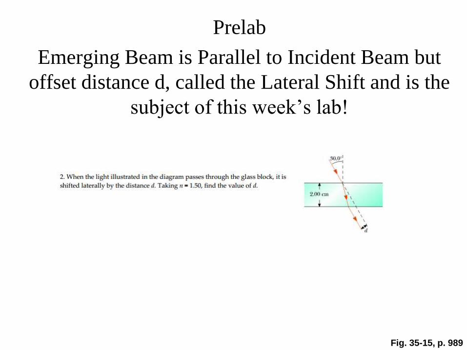
Prelab
Emerging Beam is Parallel to Incident Beam but
offset distance d, called the Lateral Shift and is the
subject of this week’s lab!
Fig. 35-15, p. 989

Following the Reflected and
Refracted Rays •Ray is the incident ray.
•Ray is the reflected ray.
•Ray is refracted into the lucite.
•Ray is internally reflected in the lucite.
•Ray is refracted as it enters the air from the lucite. Section 35.5
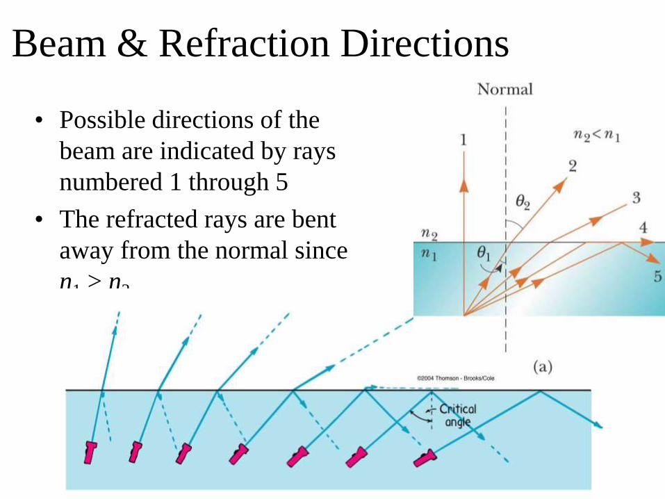
Beam & Refraction Directions
• Possible directions of the
beam are indicated by rays
numbered 1 through 5
• The refracted rays are bent
away from the normal since
n1 > n2
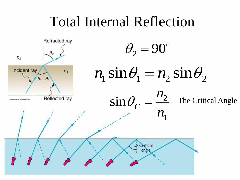
Total Internal Reflection
2
1
sin C
n
n
2 90
1 1 2 2sin sinn n
The Critical Angle
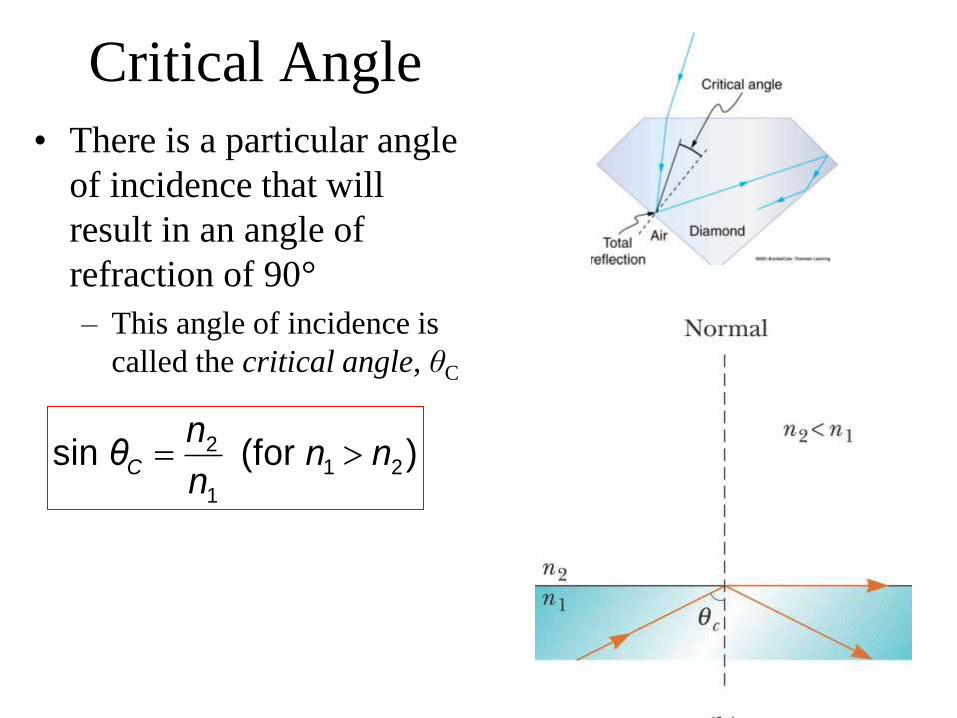
Critical Angle
• There is a particular angle
of incidence that will
result in an angle of
refraction of 90°
– This angle of incidence is
called the critical angle, θC
2
1 2
1
sin (for )C
nθ n n
n
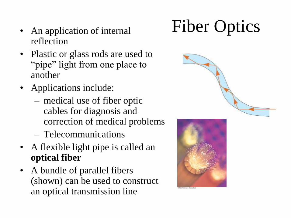
Fiber Optics • An application of internal reflection
• Plastic or glass rods are used to “pipe” light from one place to another
• Applications include:
– medical use of fiber optic cables for diagnosis and correction of medical problems
– Telecommunications
• A flexible light pipe is called an optical fiber
• A bundle of parallel fibers (shown) can be used to construct an optical transmission line
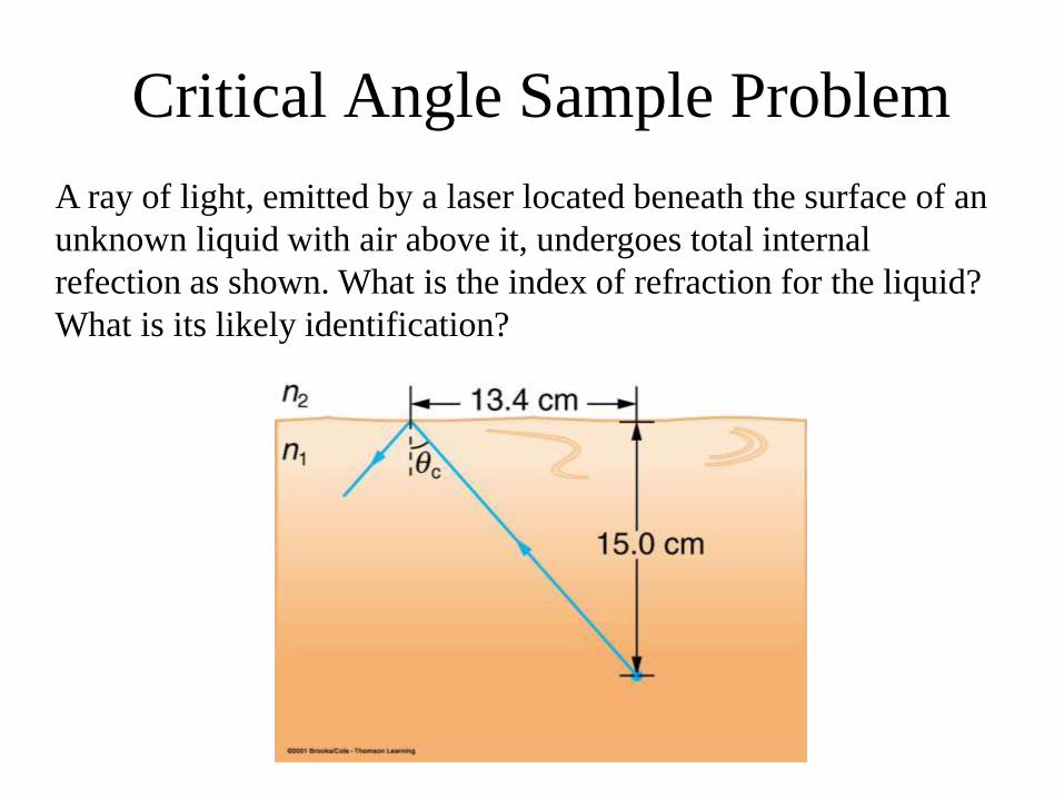
Critical Angle Sample Problem
A ray of light, emitted by a laser located beneath the surface of an
unknown liquid with air above it, undergoes total internal
refection as shown. What is the index of refraction for the liquid?
What is its likely identification?
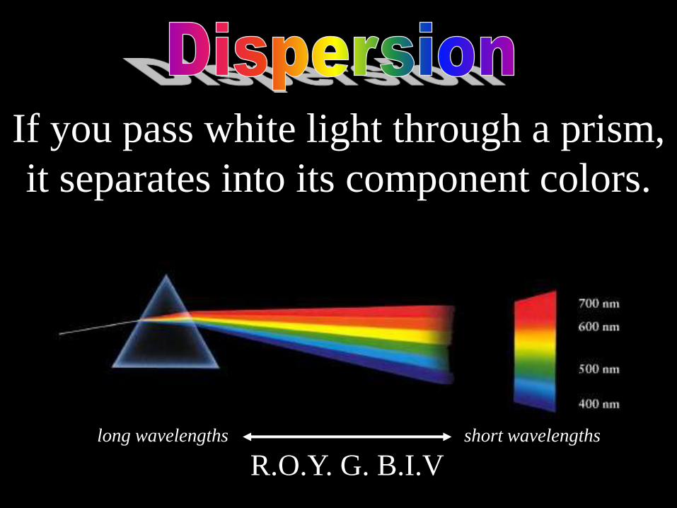
If you pass white light through a prism,
it separates into its component colors.
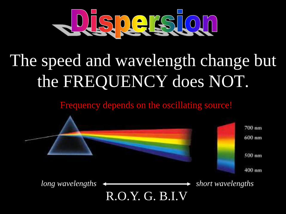
R.O.Y. G. B.I.V long wavelengths short wavelengths

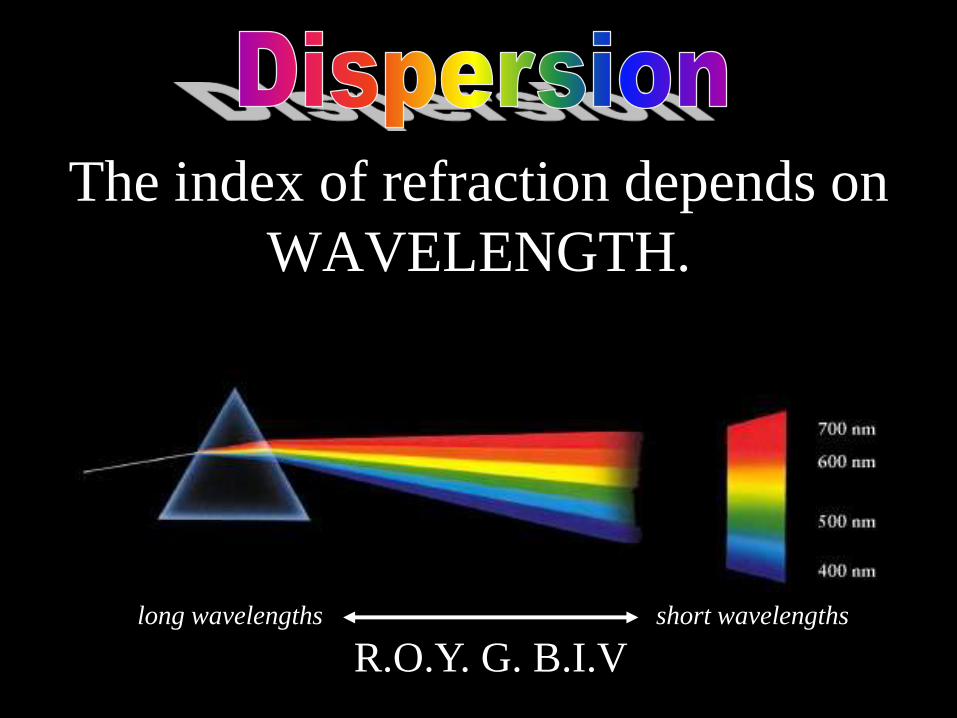
The index of refraction depends on
WAVELENGTH.
R.O.Y. G. B.I.V long wavelengths short wavelengths

The speed and wavelength change but
the FREQUENCY does NOT.
R.O.Y. G. B.I.V long wavelengths short wavelengths
Fr Frequency depends on the oscillating source!

Why does Violet Light bend more
than Red Light? Violet light slows down more because the atoms in the material
are tuned to higher frequencies. As the violet light travels
through glass it takes more time to be absorbed and re-emitted.

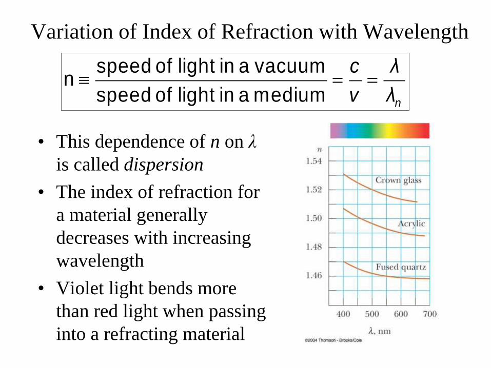
Variation of Index of Refraction with Wavelength
• This dependence of n on λ
is called dispersion
• The index of refraction for
a material generally
decreases with increasing
wavelength
• Violet light bends more
than red light when passing
into a refracting material
speed of light in a vacuum
nspeed of light in a medium n
c λ
v λ
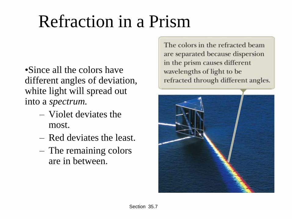
Refraction in a Prism
•Since all the colors have different angles of deviation, white light will spread out into a spectrum.
– Violet deviates the most.
– Red deviates the least.
– The remaining colors are in between.
Section 35.7

Dispersion via Diffraction
: sin , 0,1,2,3constructive d m m

If you pass white light through a prism,
it separates into its component colors.
R.O.Y. G. B.I.V long wavelengths short wavelengths
The index of refraction depends on
WAVELENGTH.
R.O.Y. G. B.I.V long wavelengths short wavelengths
The speed and wavelength change but
the FREQUENCY does NOT.
R.O.Y. G. B.I.V long wavelengths short wavelengths
Fr Frequency depends on the oscillating source!

Why does Violet Light bend more
than Red Light? Violet light slows down more because the atoms in the material
are tuned to higher frequencies. As the violet light travels
through glass it takes more time to be absorbed and re-emitted.
Variation of Index of Refraction with Wavelength
• This dependence of n on λ
is called dispersion
• The index of refraction for
a material generally
decreases with increasing
wavelength
• Violet light bends more
than red light when passing
into a refracting material
speed of light in a vacuum
nspeed of light in a medium n
c λ
v λ
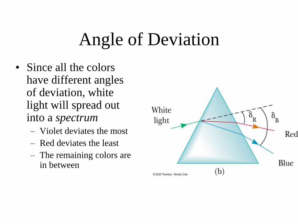
Angle of Deviation
• Since all the colors have different angles of deviation, white light will spread out into a spectrum – Violet deviates the most
– Red deviates the least
– The remaining colors are in between
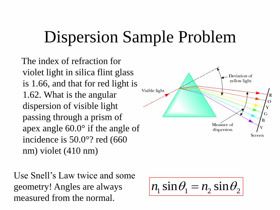
Dispersion Sample Problem
The index of refraction for
violet light in silica flint glass
is 1.66, and that for red light is
1.62. What is the angular
dispersion of visible light
passing through a prism of
apex angle 60.0° if the angle of
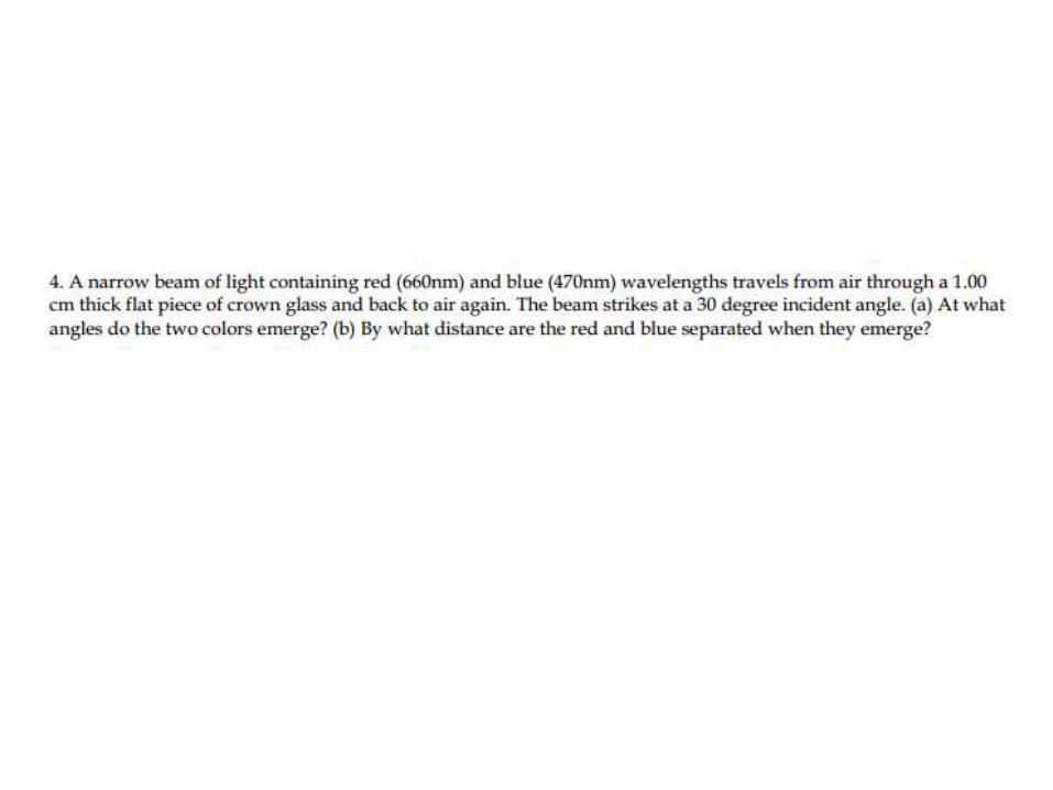
incidence is 50.0°? red (660
nm) violet (410 nm)
1 1 2 2sin sinn n Use Snell’s Law twice and some
geometry! Angles are always
measured from the normal.
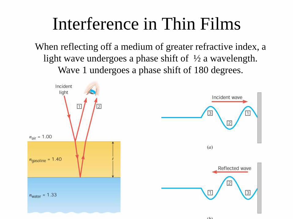
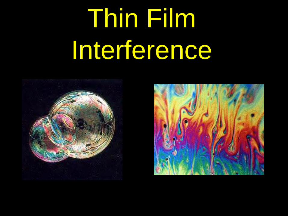
Interference in Thin Films When reflecting off a medium of greater refractive index, a
light wave undergoes a phase shift of ½ a wavelength.
Wave 1 undergoes a phase shift of 180 degrees.
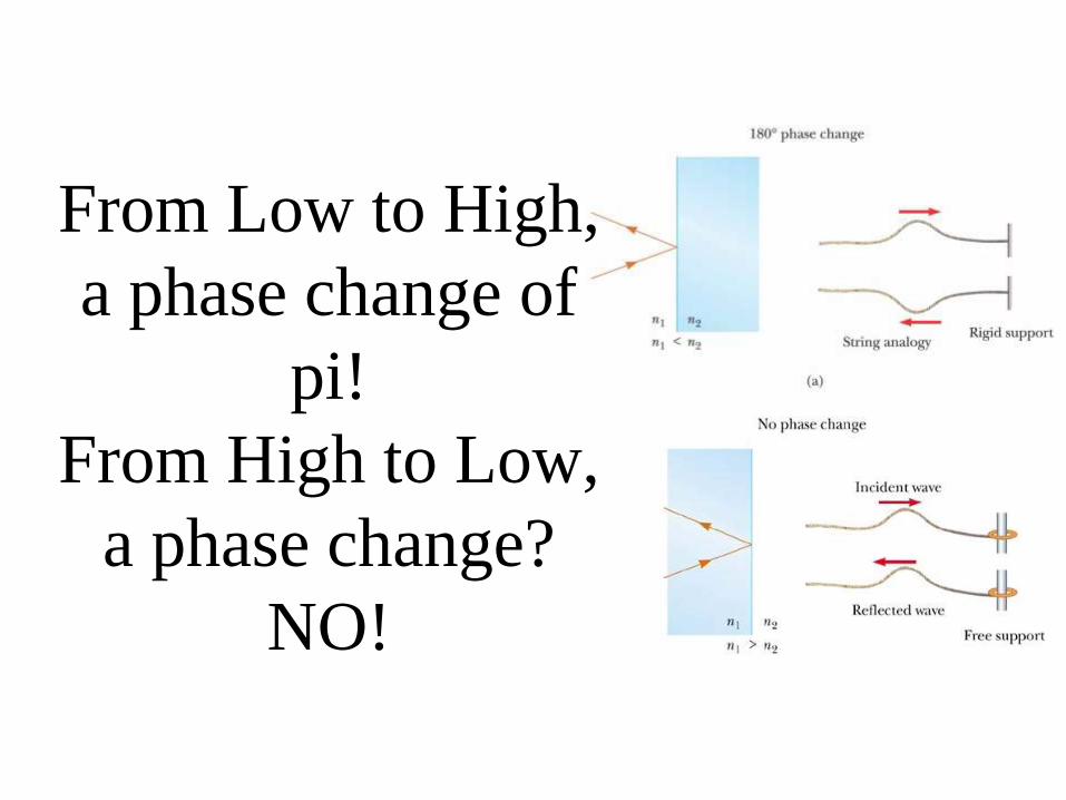
From Low to High,
a phase change of
pi!
From High to Low,
a phase change?
NO!
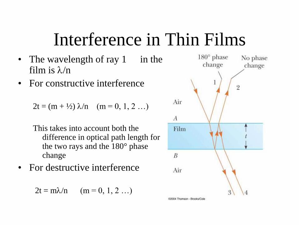
Interference in Thin Films • The wavelength of ray 1 in the
film is /n
• For constructive interference
2t = (m + ½) /n (m = 0, 1, 2 …)
This takes into account both the difference in optical path length for the two rays and the 180° phase change
• For destructive interference
2t = m/n (m = 0, 1, 2 …)
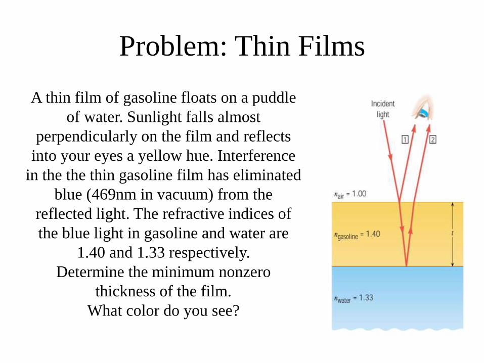
A thin film of gasoline floats on a puddle
of water. Sunlight falls almost
perpendicularly on the film and reflects
into your eyes a yellow hue. Interference
in the the thin gasoline film has eliminated
blue (469nm in vacuum) from the
reflected light. The refractive indices of
the blue light in gasoline and water are
1.40 and 1.33 respectively.
Determine the minimum nonzero
thickness of the film.
What color do you see?
Problem: Thin Films
Thin Film Interference
The light reflected from a soap bubble
(n = 1.40) appears red ( = 640 nm). What is the minimum thickness (in nm)?
a. 124
b.104
c. 114
d.134
e. 234

How are Rainbows Formed?
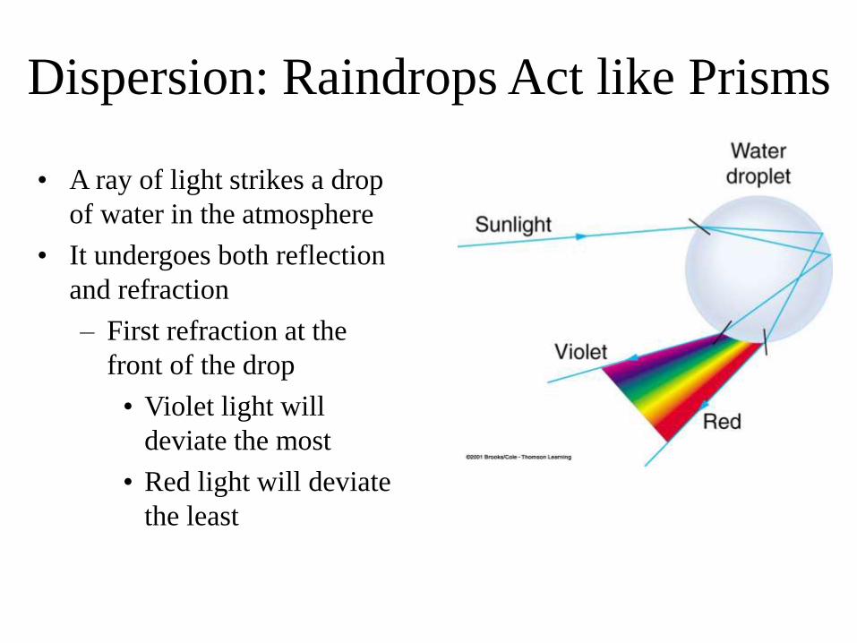
Dispersion: Raindrops Act like Prisms
• A ray of light strikes a drop
of water in the atmosphere
• It undergoes both reflection
and refraction
– First refraction at the
front of the drop
• Violet light will
deviate the most
• Red light will deviate
the least
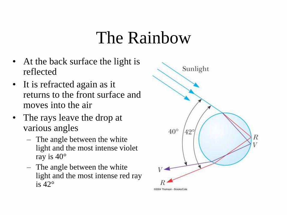
The Rainbow
• At the back surface the light is reflected
• It is refracted again as it returns to the front surface and moves into the air
• The rays leave the drop at various angles
– The angle between the white light and the most intense violet ray is 40°
– The angle between the white light and the most intense red ray is 42°
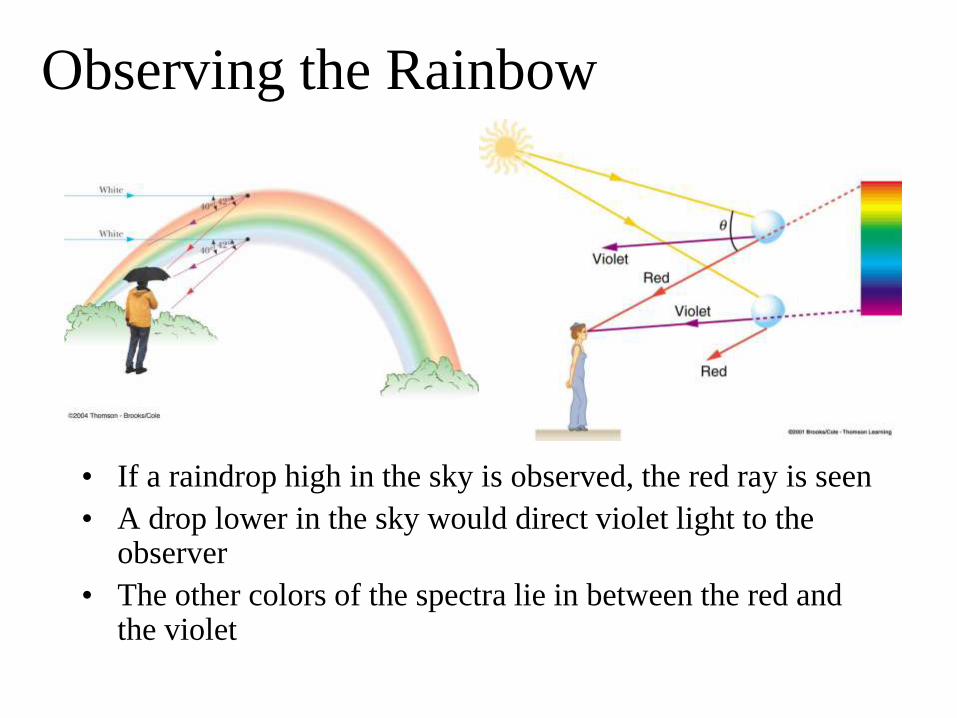
Observing the Rainbow
• If a raindrop high in the sky is observed, the red ray is seen
• A drop lower in the sky would direct violet light to the observer
• The other colors of the spectra lie in between the red and the violet
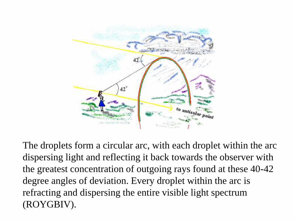
The droplets form a circular arc, with each droplet within the arc
dispersing light and reflecting it back towards the observer with
the greatest concentration of outgoing rays found at these 40-42
degree angles of deviation. Every droplet within the arc is
refracting and dispersing the entire visible light spectrum
(ROYGBIV).
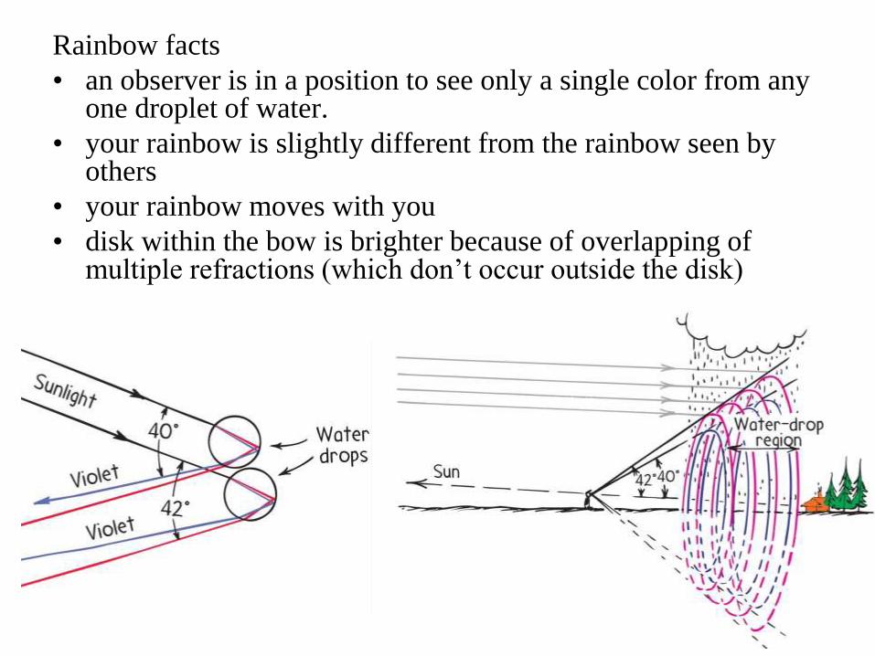
Rainbow facts
• an observer is in a position to see only a single color from any one droplet of water.
• your rainbow is slightly different from the rainbow seen by others
• your rainbow moves with you
• disk within the bow is brighter because of overlapping of multiple refractions (which don’t occur outside the disk)
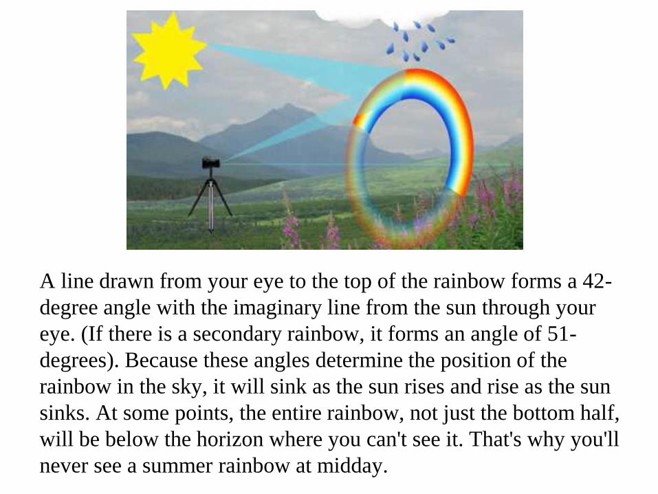
A line drawn from your eye to the top of the rainbow forms a 42-
degree angle with the imaginary line from the sun through your
eye. (If there is a secondary rainbow, it forms an angle of 51-
degrees). Because these angles determine the position of the
rainbow in the sky, it will sink as the sun rises and rise as the sun
sinks. At some points, the entire rainbow, not just the bottom half,
will be below the horizon where you can't see it. That's why you'll
never see a summer rainbow at midday.
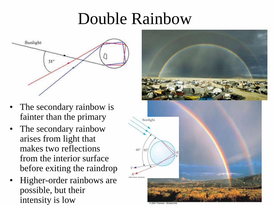
Double Rainbow
• The secondary rainbow is fainter than the primary
• The secondary rainbow arises from light that makes two reflections from the interior surface before exiting the raindrop
• Higher-order rainbows are possible, but their intensity is low

• Halos are caused by the light of the sun or moon passing through a very thin layer of
cirruform (ice-crystal) clouds in the upper atmosphere. The ice crystals refract the light
of the moon, similar to the way water droplets in the lower atmosphere can refract
sunlight to produce a rainbow. Just like a rainbow, strong halos can have bands of color
in them, due to slightly different refractive properties of the ice crystals for different
colors. Essentially, halos ARE rainbows caused by primary refraction in ice crystals.
• Some interesting facts about halos: Halos always occur exactly 22 degrees away from
the sun or moon. Occasionally, intense halos can be double halos, just as intense
rainbows can be doubled. Intense halos can also produce "moondogs" or "sundogs,"
very bright regions on the halo evenly spaced at 90 degree intervals around the halo.
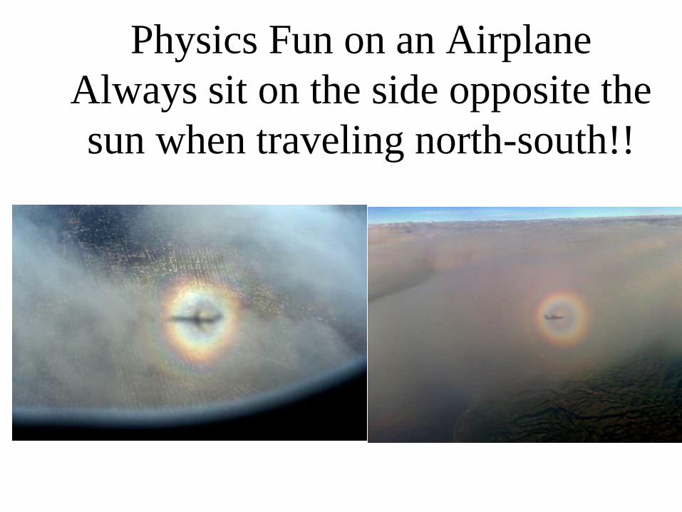
Physics Fun on an Airplane
Always sit on the side opposite the
sun when traveling north-south!!
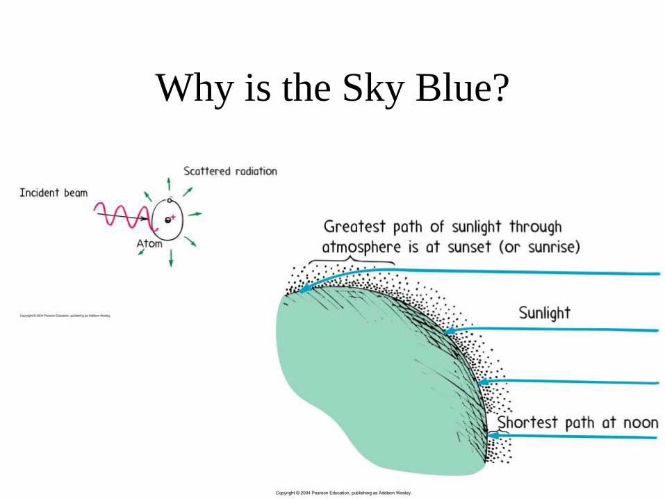
Why is the Sky Blue?
Galileo
In the early 17th century, many scientists believed that there was no
such thing as the "speed of light"; they thought light could travel any
distance in no time at all. Galileo disagreed, and he came up with an
experiment to measure light's velocity: he and his assistant each took
a shuttered lantern, and they stood on hilltops one mile apart. Galileo
flashed his lantern, and the assistant was supposed to open the shutter
to his own lantern as soon as he saw Galileo's light. Galileo would
then time how long it took before he saw the light from the other
hilltop. The problem was that the speed of light is simply too fast to
be measured this way; light takes such a short time (about 0.000005
seconds, in fact) to travel one mile that there's no way the interval
could have been measured using the tools Galileo had.

The Speed of Light? • 186,000 miles per second
• 300,000 kilometers per second
• 3 x 10⁸ m/s
• first successfully determined by Danish astronomer Ole Roemer in 1675: 2.3 x 10⁸ m/s
• First Terrestrial Measurement by Fizeau in 1849: 2.9979 x 10⁸ m/s
• In 1926, Michelson used a rotating prism to measure the time it took light to make a round trip from Mount Wilson to Mount San Antonio in California, a distance of about 22 miles (36 km). The precise measurements yielded a speed of 186,285 miles per second (299,796 kilometres per second).

Huygens’s Principle
Construction for a Plane Wave
• Huygens assumed that light is a form of wave motion rather than a stream of particles
• All points on a given wave front are taken as point sources for the production of spherical secondary waves, called wavelets, which propagate outward through a medium with speeds characteristic of waves in that medium
• After some time has passed, the new position of the wave front is the surface tangent to the wavelets
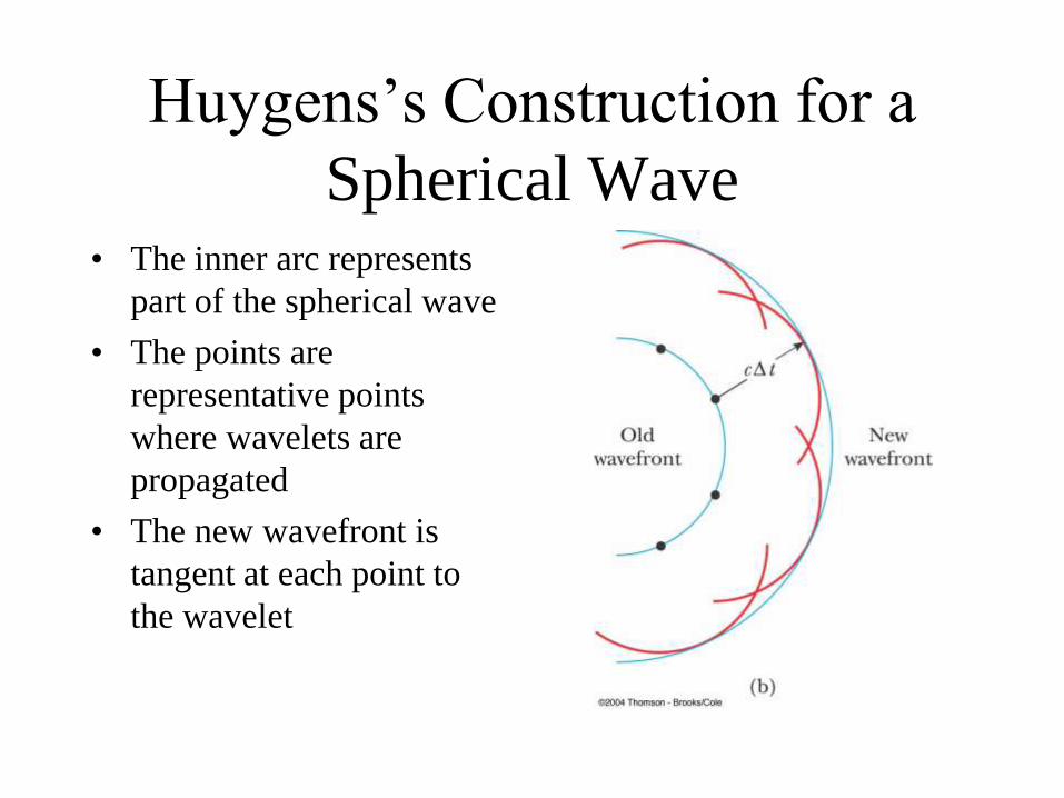
Huygens’s Construction for a
Spherical Wave • The inner arc represents
part of the spherical wave
• The points are
representative points
where wavelets are
propagated
• The new wavefront is
tangent at each point to
the wavelet

Huygens’s Principle Prove the
Laws of Reflection & Refraction
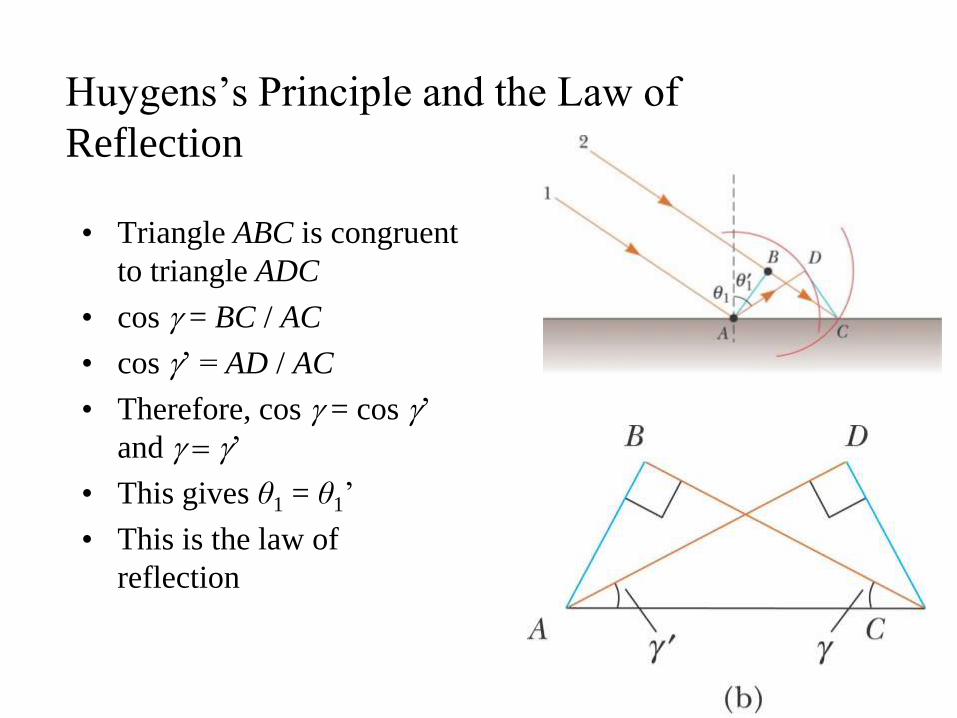
Huygens’s Principle and the Law of
Reflection
• Triangle ABC is congruent
to triangle ADC
• cos g = BC / AC
• cos g’ = AD / AC
• Therefore, cos g = cos g’
and g g’
• This gives θ1 = θ1’
• This is the law of
reflection
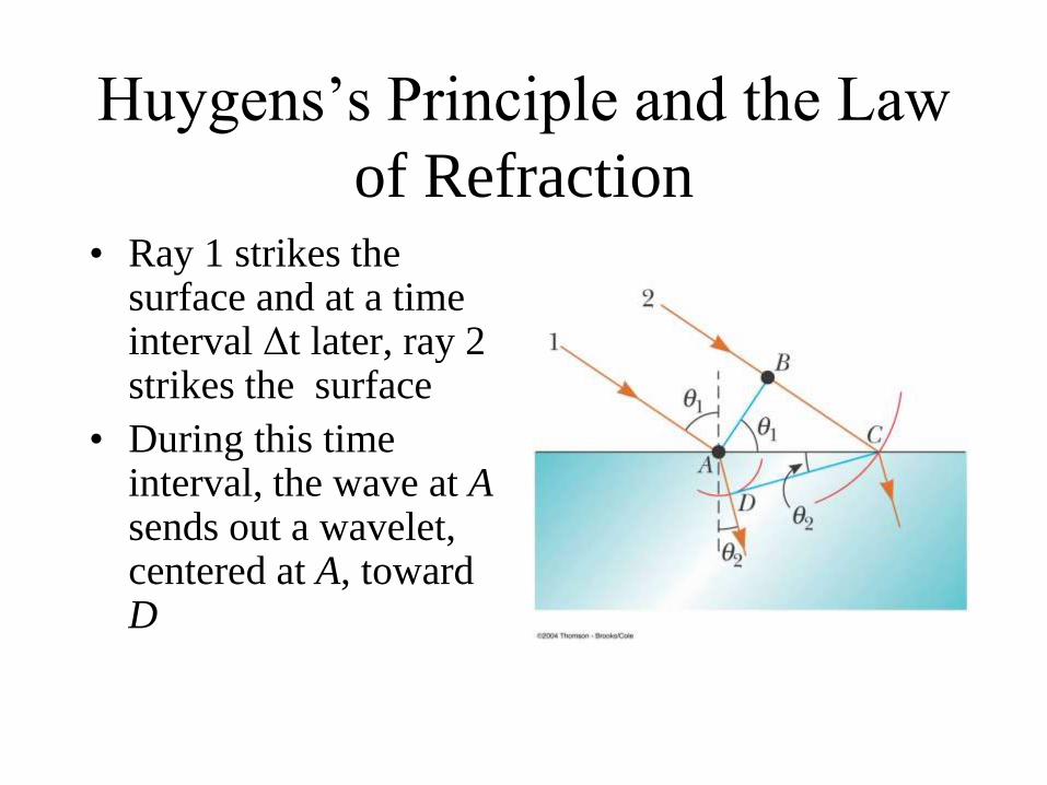
Huygens’s Principle and the Law
of Refraction • Ray 1 strikes the
surface and at a time interval Δt later, ray 2 strikes the surface
• During this time interval, the wave at A sends out a wavelet, centered at A, toward D
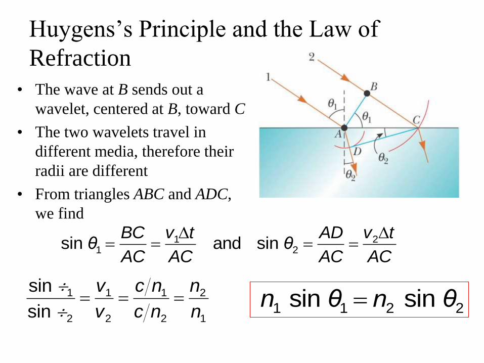
Huygens’s Principle and the Law of
Refraction
• The wave at B sends out a
wavelet, centered at B, toward C
• The two wavelets travel in
different media, therefore their
radii are different
• From triangles ABC and ADC,
we find
1 21 2sin and sin
BC v t AD v tθ θ
AC AC AC AC
1 1 1 2
2 2 2 1
sin
sin
v c n n
v c n n1 1 2 2 sin sin n θ n θ
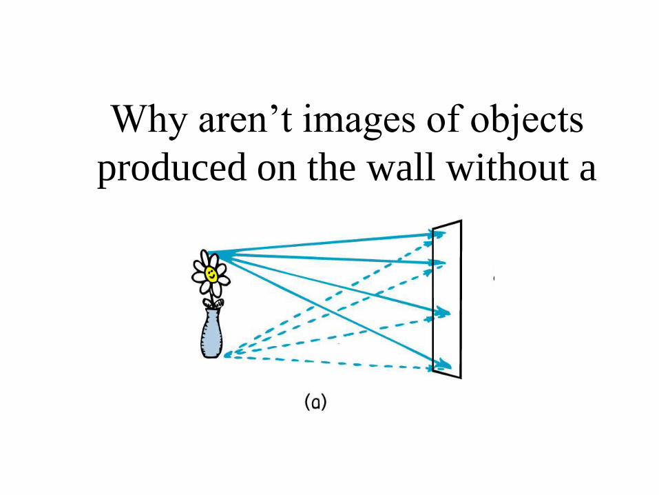
Why aren’t images of objects
produced on the wall without a
lens or hole?
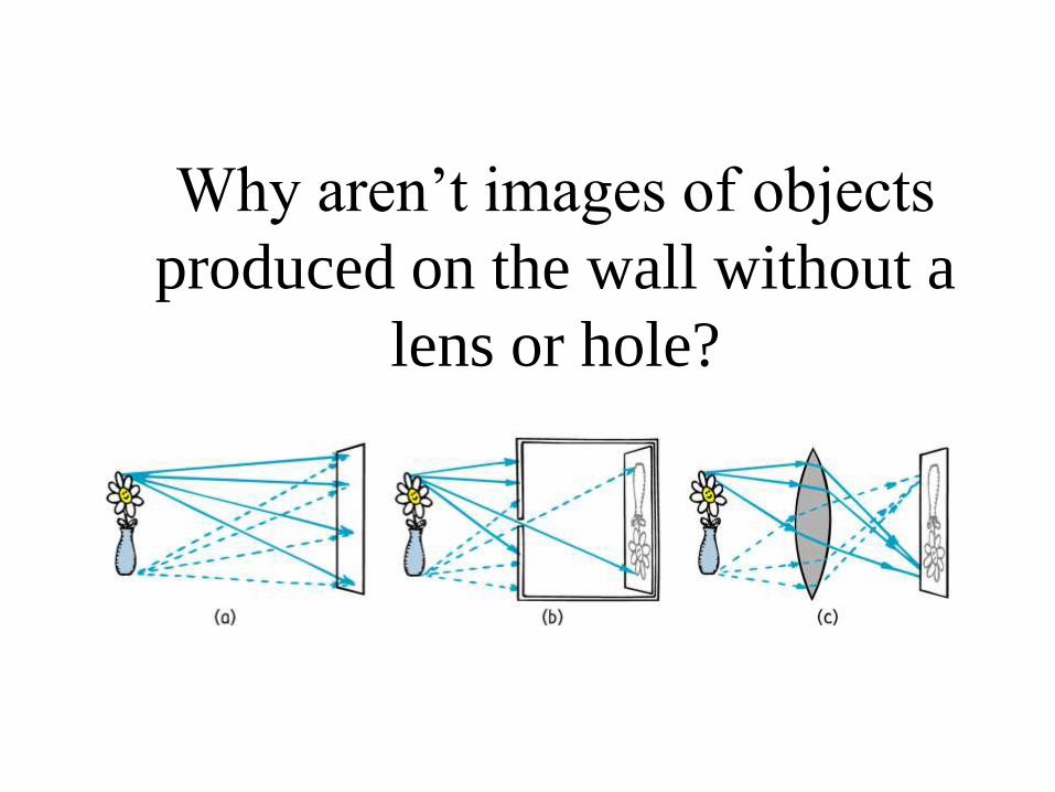
Why aren’t images of objects
produced on the wall without a
lens or hole?
Law of Reflection
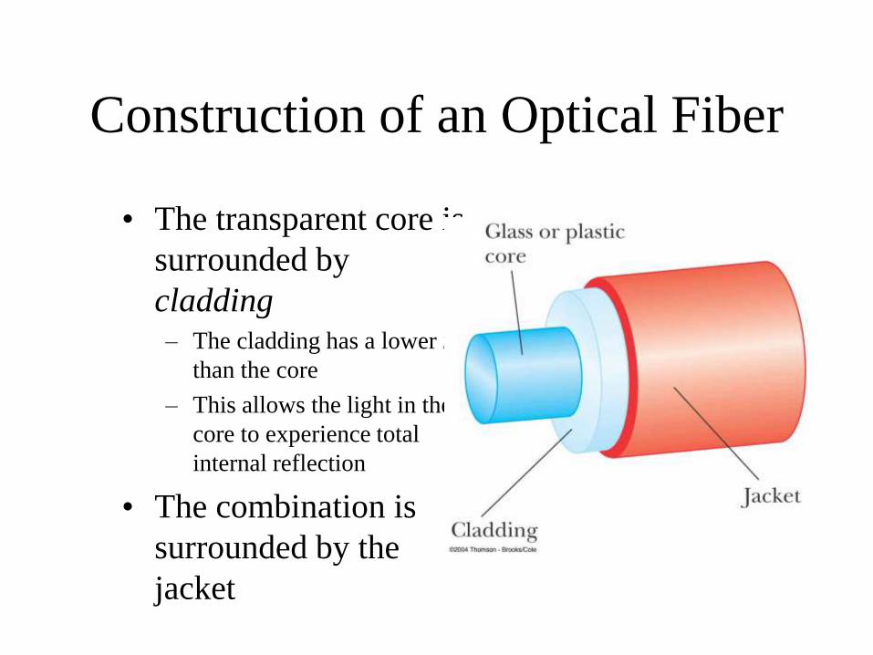
Construction of an Optical Fiber
• The transparent core is
surrounded by
cladding – The cladding has a lower n
than the core
– This allows the light in the
core to experience total
internal reflection
• The combination is
surrounded by the
jacket
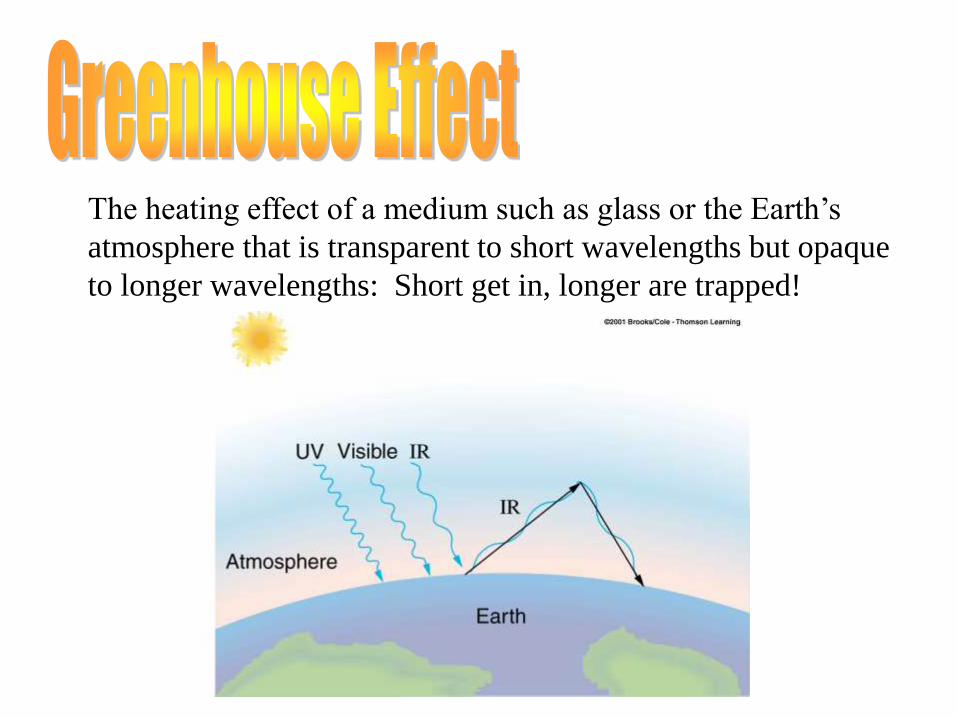
The heating effect of a medium such as glass or the Earth’s
atmosphere that is transparent to short wavelengths but opaque
to longer wavelengths: Short get in, longer are trapped!
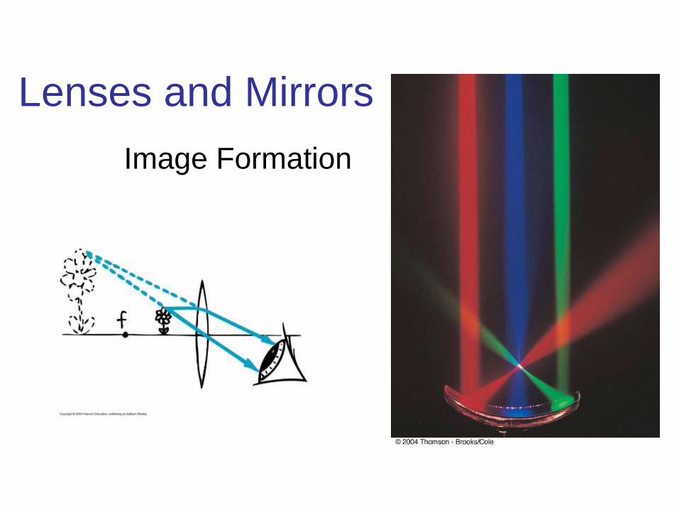
Lenses and Mirrors
Image Formation
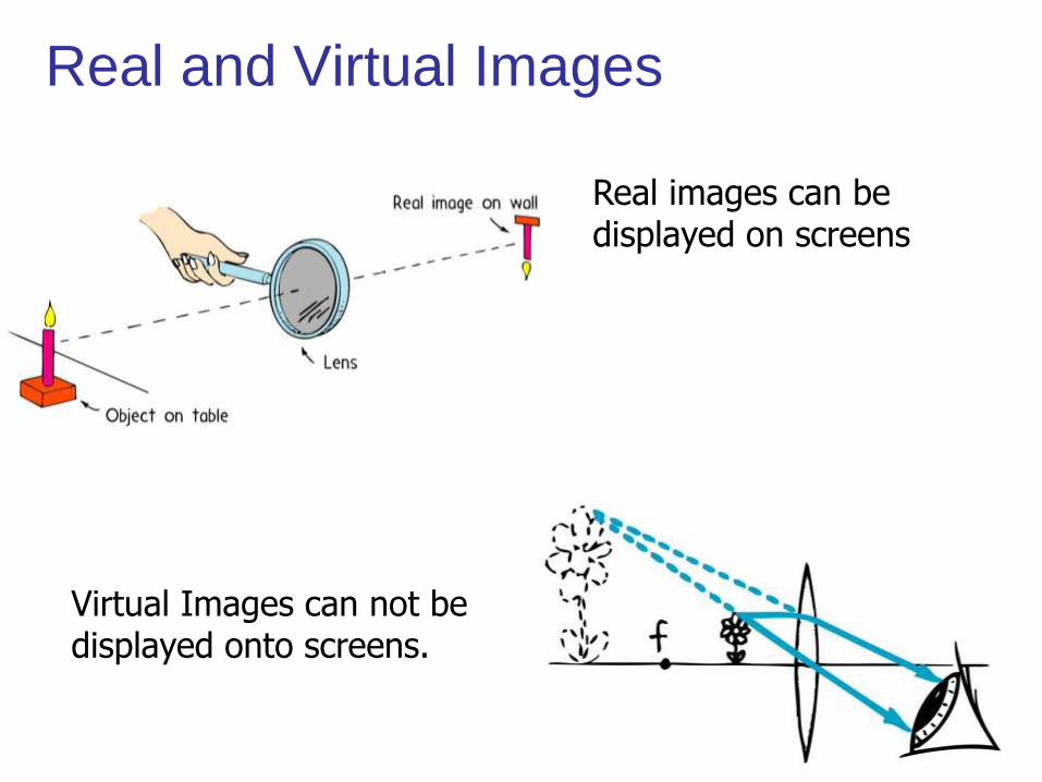
Real and Virtual Images
Virtual Images can not be displayed onto screens.
Real images can be displayed on screens
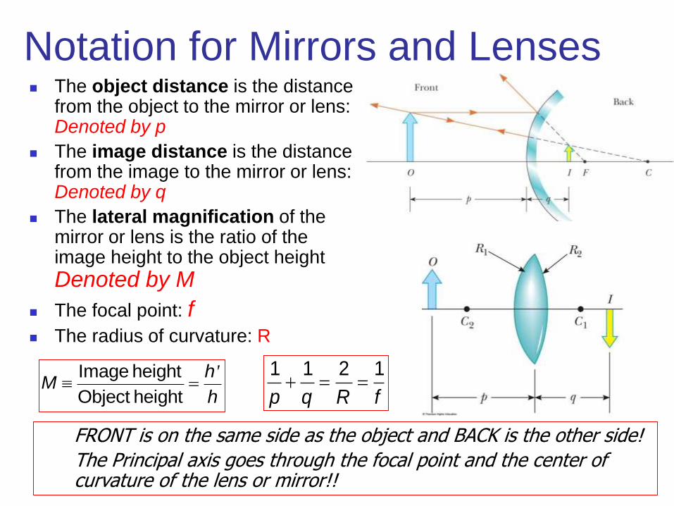
Notation for Mirrors and Lenses The object distance is the distance
from the object to the mirror or lens: Denoted by p
The image distance is the distance from the image to the mirror or lens: Denoted by q
The lateral magnification of the mirror or lens is the ratio of the image height to the object height
Denoted by M
The focal point: f The radius of curvature: R
1 1 2 1
p q R f
FRONT is on the same side as the object and BACK is the other side!
The Principal axis goes through the focal point and the center of curvature of the lens or mirror!!
Image height
Object height
'hM
h
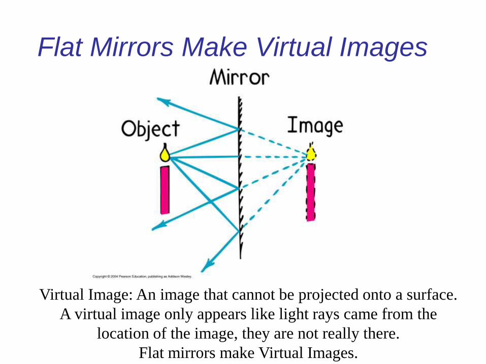
Flat Mirrors Make Virtual Images
Virtual Image: An image that cannot be projected onto a surface.
A virtual image only appears like light rays came from the
location of the image, they are not really there.
Flat mirrors make Virtual Images.
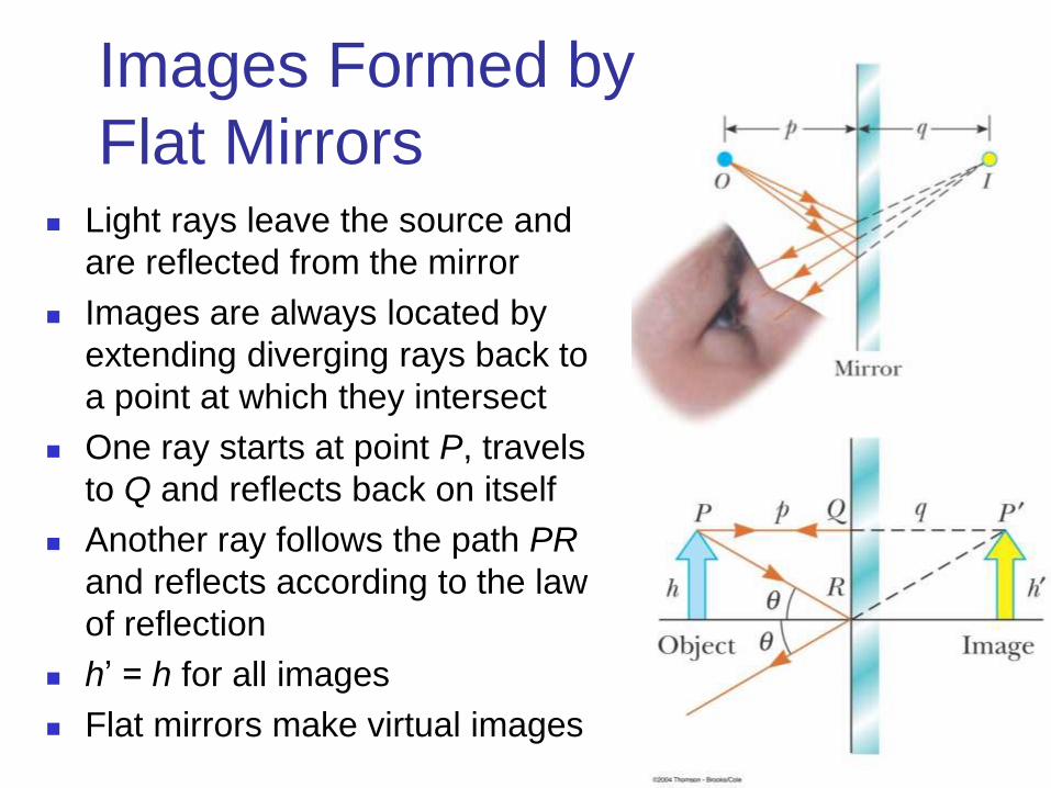
Images Formed by
Flat Mirrors Light rays leave the source and
are reflected from the mirror
Images are always located by
extending diverging rays back to
a point at which they intersect
One ray starts at point P, travels
to Q and reflects back on itself
Another ray follows the path PR
and reflects according to the law
of reflection
h’ = h for all images
Flat mirrors make virtual images
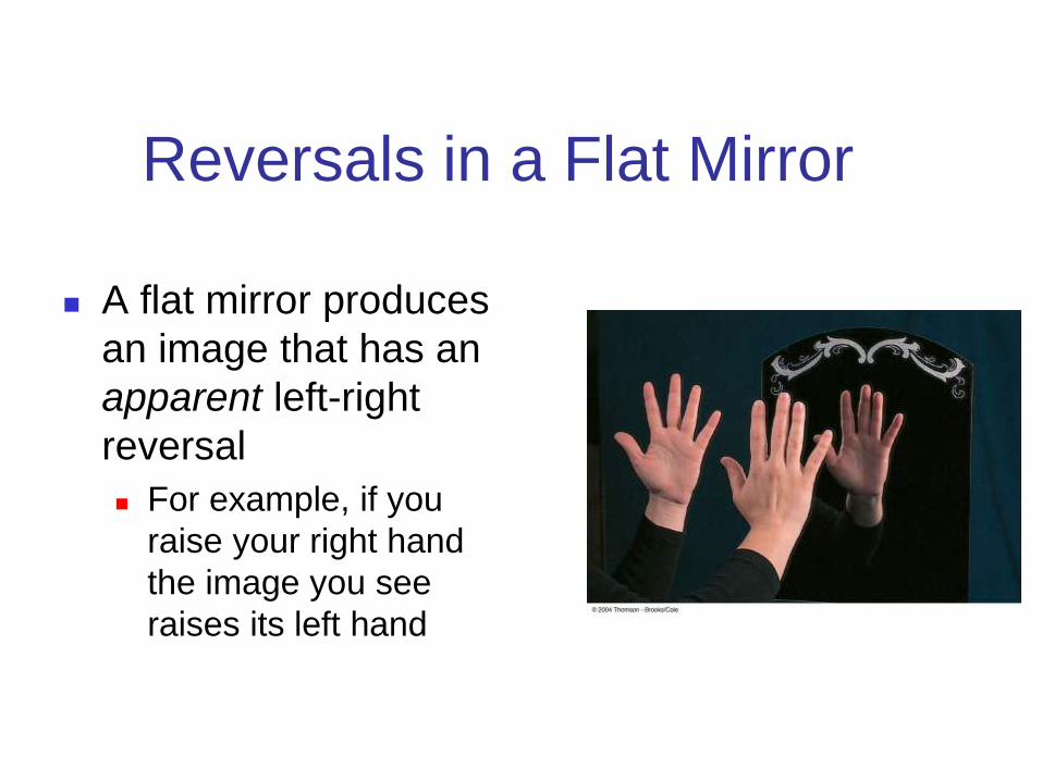
Reversals in a Flat Mirror
A flat mirror produces
an image that has an
apparent left-right
reversal
For example, if you
raise your right hand
the image you see
raises its left hand
Properties of the Image Formed
by a Flat Mirror – Summary
The image is as far behind the mirror as the object is in front |p| = |q|
The image is unmagnified The image height is the same as the object height
h’ = h and M = 1
The image is virtual
The image is upright It has the same orientation as the object
There is a front-back reversal in the image
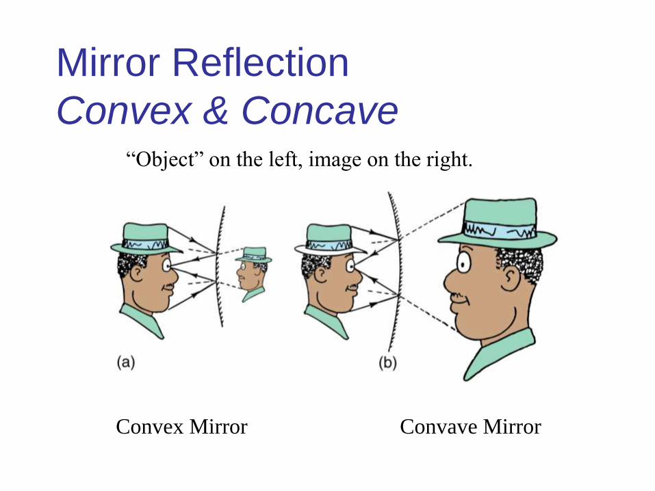
Mirror Reflection
Convex & Concave
Convex Mirror Convave Mirror
“Object” on the left, image on the right.
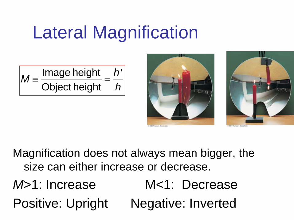
Lateral Magnification
Magnification does not always mean bigger, the
size can either increase or decrease.
M>1: Increase M<1: Decrease
Positive: Upright Negative: Inverted
Image height
Object height
'hM
h
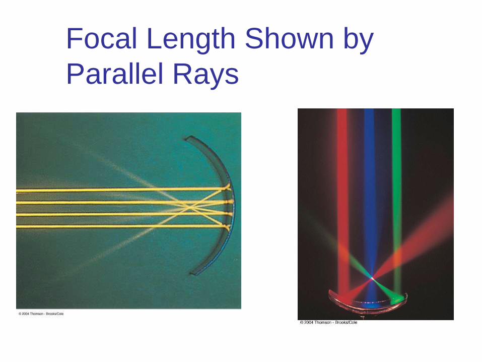
Focal Length Shown by
Parallel Rays

Focal Length& Radius of
Curvature
When the object is very far
away, then p → ∞ and the
incoming rays are essentially
parallel
In this special case, the image
point is called the focal point
The distance from the mirror to
the focal point is called the
focal length
The focal length is ½ the radius of
curvature
R = 2f
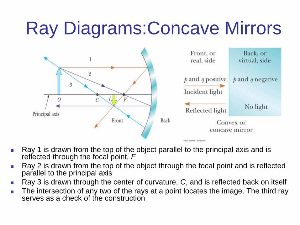
Ray Diagrams:Concave Mirrors
Ray 1 is drawn from the top of the object parallel to the principal axis and is reflected through the focal point, F
Ray 2 is drawn from the top of the object through the focal point and is reflected parallel to the principal axis
Ray 3 is drawn through the center of curvature, C, and is reflected back on itself
The intersection of any two of the rays at a point locates the image. The third ray serves as a check of the construction
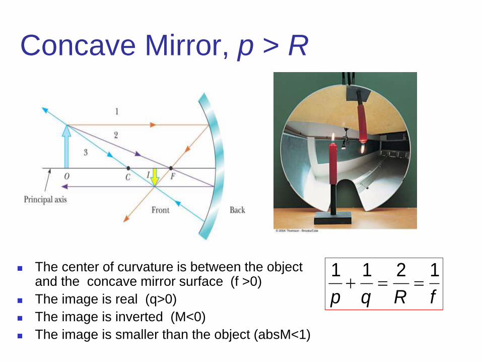
Concave Mirror, p > R
The center of curvature is between the object and the concave mirror surface (f >0)
The image is real (q>0)
The image is inverted (M<0)
The image is smaller than the object (absM<1)
1 1 2 1
p q R f

Concave Mirror, p < f
The object is between the mirror surface and the focal point (p>0)
The image is virtual (q<0)
The image is upright (M>0)
The image is larger than the object (M>1)

Ray Diagrams:Convex Mirrors
Ray 1 is drawn from the top of the object parallel to the principal axis and is reflected away from the focal point, F
Ray 2 is drawn from the top of the object toward the focal point and is reflected parallel to the principal axis
Ray 3 is drawn through the center of curvature, C, on the back side of the mirror and is reflected back on itself

Convex Mirror
The object is in front of a convex mirror (p>0)
The focal point distance q is negative (q <0)
The image is always virtual and upright (M>0)
As the object distance decreases, the virtual image size increases
The image is smaller than the object (0<M<1)
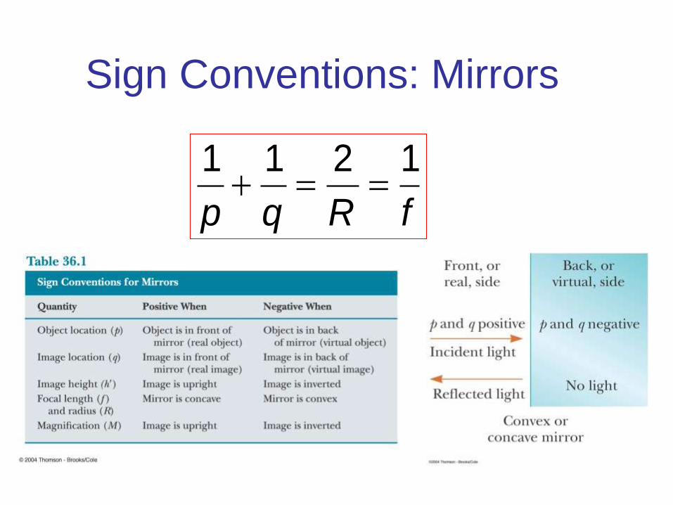
Sign Conventions: Mirrors
1 1 2 1
p q R f
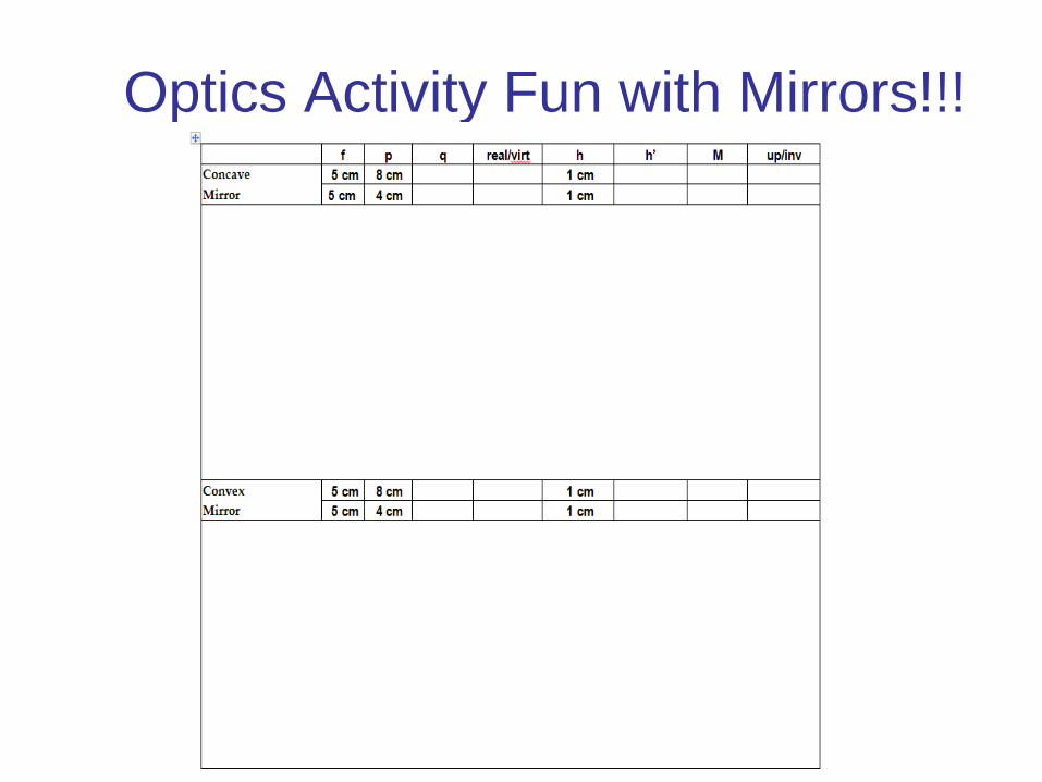
Optics Activity Fun with Mirrors!!!
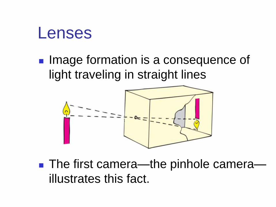
Lenses
Image formation is a consequence of
light traveling in straight lines
The first camera—the pinhole camera—
illustrates this fact.
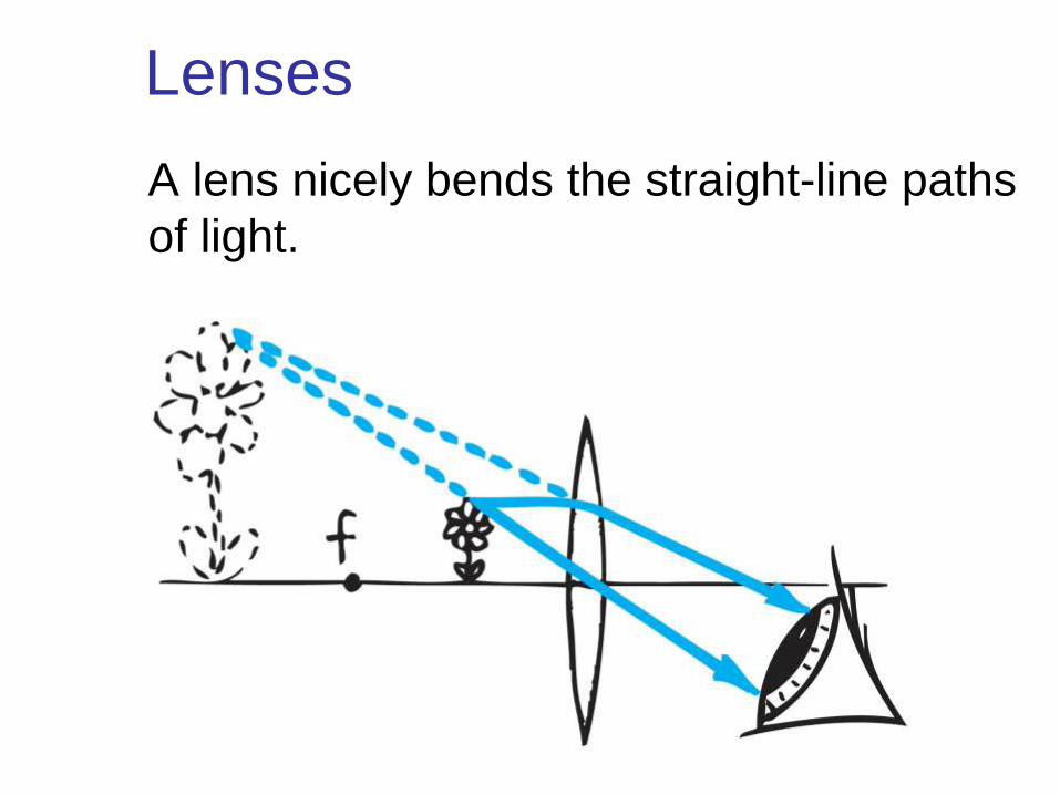
Lenses
A lens nicely bends the straight-line paths
of light.

Lenses
A converging lens can project an image.
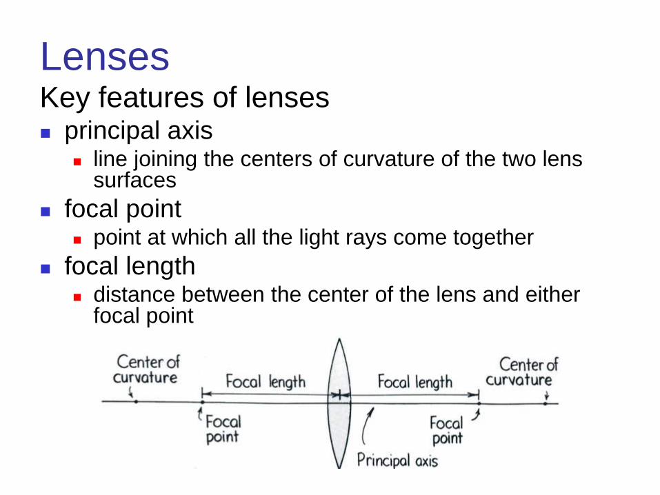
Lenses Key features of lenses principal axis
line joining the centers of curvature of the two lens surfaces
focal point point at which all the light rays come together
focal length distance between the center of the lens and either
focal point
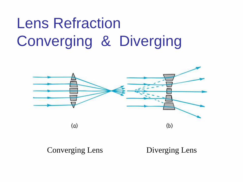
Lens Refraction
Converging & Diverging
Converging Lens Diverging Lens
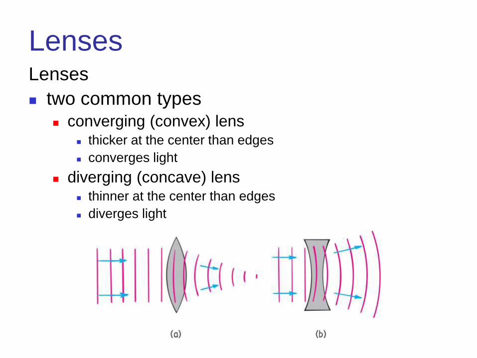
Lenses Lenses
two common types converging (convex) lens
thicker at the center than edges
converges light
diverging (concave) lens thinner at the center than edges
diverges light
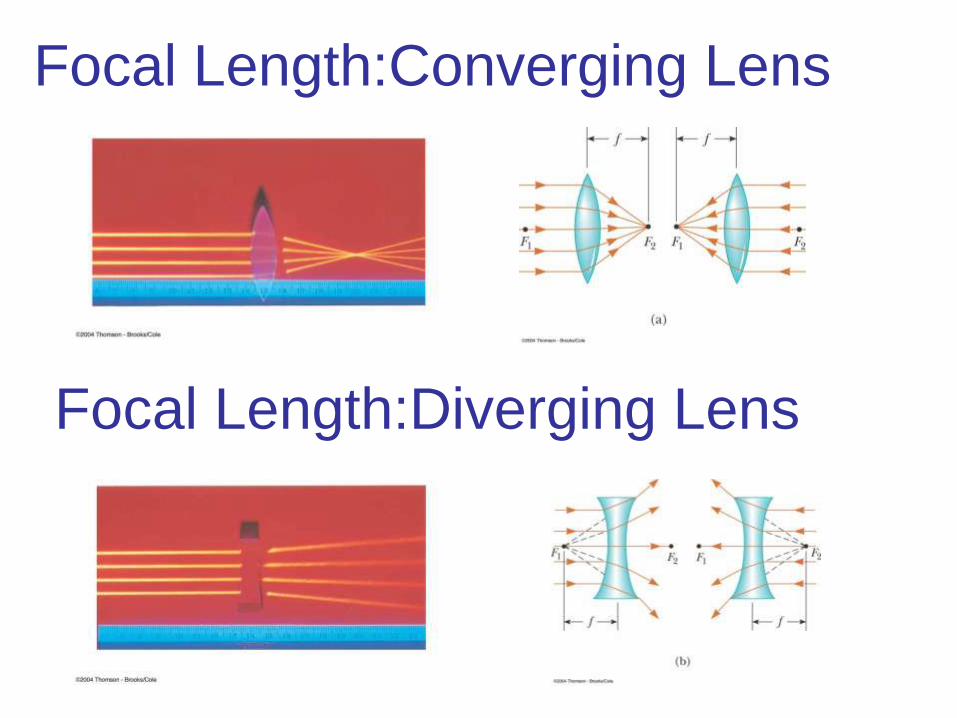
Focal Length:Converging Lens
Focal Length:Diverging Lens

Converging Thin Lens Shapes
These are examples
of converging lenses
They have positive
focal lengths
They are thickest in
the middle
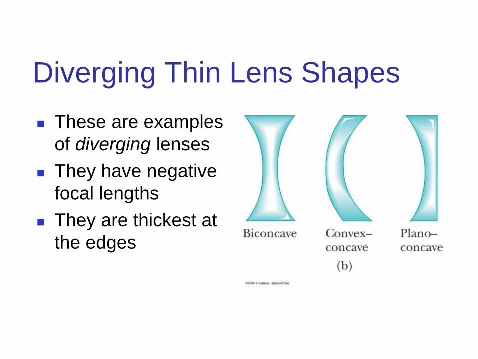
Diverging Thin Lens Shapes
These are examples
of diverging lenses
They have negative
focal lengths
They are thickest at
the edges
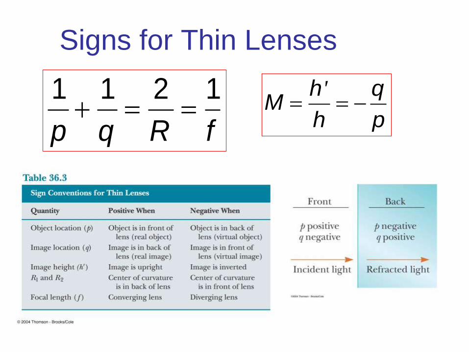
Signs for Thin Lenses
1 1 2 1
p q R f
'h qM
h p
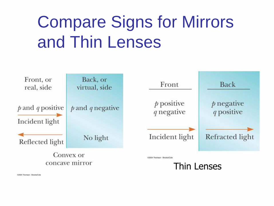
Compare Signs for Mirrors
and Thin Lenses
Thin Lenses
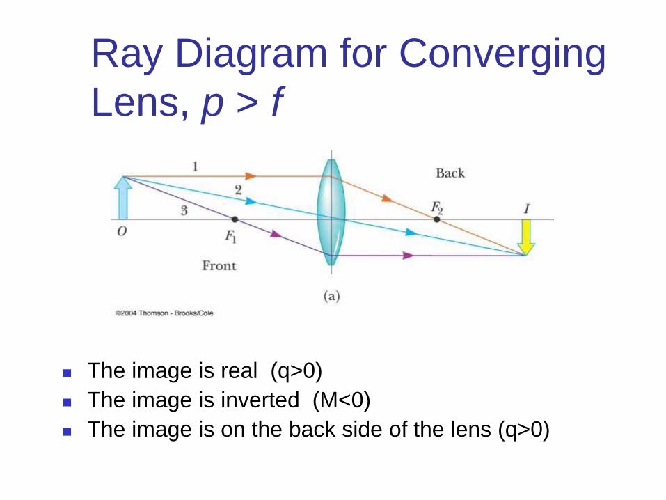
Ray Diagram for Converging
Lens, p > f
The image is real (q>0)
The image is inverted (M<0)
The image is on the back side of the lens (q>0)
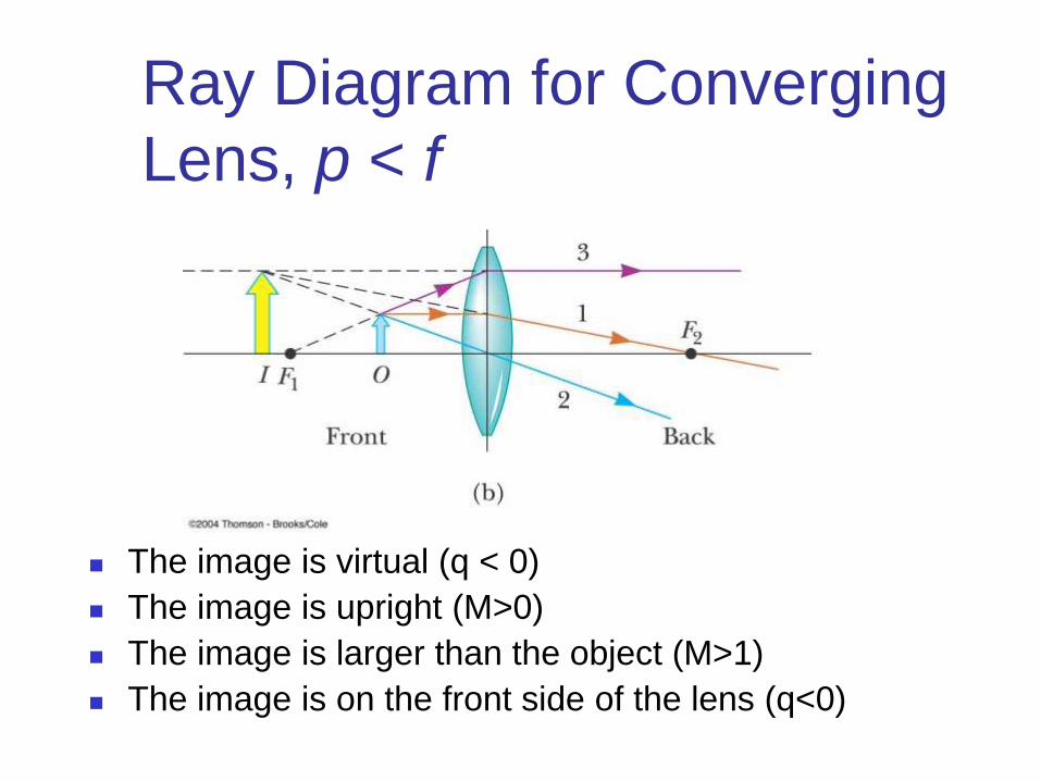
Ray Diagram for Converging
Lens, p < f
The image is virtual (q < 0)
The image is upright (M>0)
The image is larger than the object (M>1)
The image is on the front side of the lens (q<0)

Ray Diagram for Diverging
Lens
For a diverging lens, the image is always virtual
and upright (M>0)
This is regardless of where the object is placed
The image is on the front side of the lens (q<0)

Optics Activity Fun with Lenses!!!!
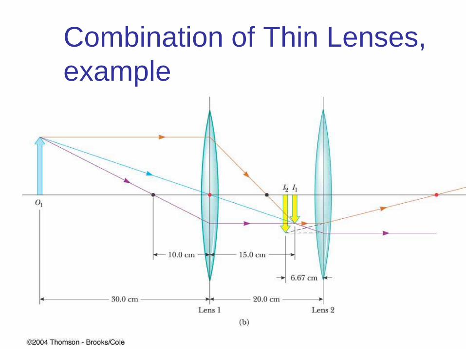
Combination of Thin Lenses,
example