Chapter 24 Wave Optics. General Physics Review – optical elements.

1

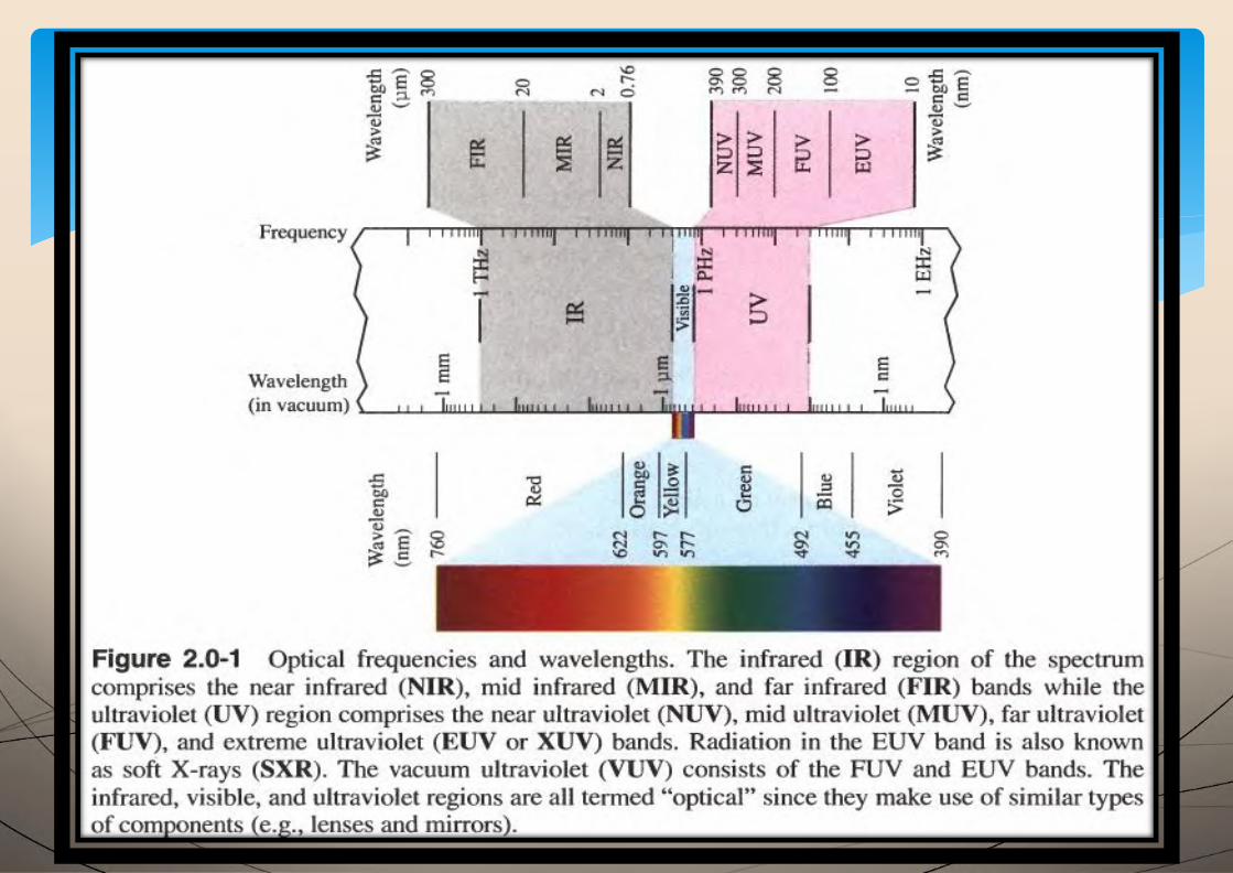
Chapter 2. Wave Optics
Ray
Optics
Wave Optics
Quantum
Optics
Electromagnetic
Optics
2
3
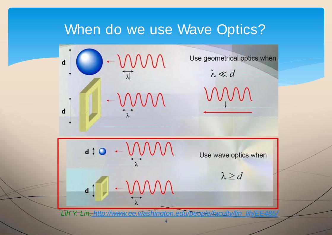
When do we use Wave Optics?
Lih Y. Lin, http://www.ee.washington.edu/people/faculty/lin_lih/EE485/4
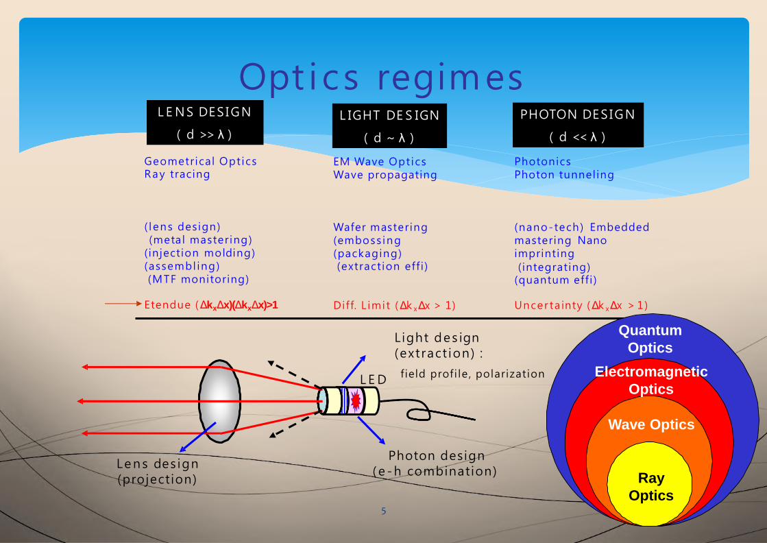
L E NS DES IGN
( d >> λ )
L IGHT DE S IGN
( d ~ λ )
PHOTON DES IGN
( d << λ )
Geometrical OpticsRay tracing
( lens design)(metal mastering)
(injection molding)(assembl ing)(MTF monitoring)
Etendue (ΔkxΔx)(ΔkxΔx)>1
EM Wave OpticsWave propagating
Wafer mastering(emboss ing (packaging)(extraction eff i )
Diff. L imit (Δk xΔx > 1)
PhotonicsPhoton tunneling
(nano-tech) Embeddedmastering Nanoimprinting(integrating)(quantum effi)
Uncer ta inty (Δk xΔx > 1)
Lens des ign(projection)
Light des ign(extract ion) :
L E Dfield profi le , polarization
Photon design(e -h combination)
5
Opt ics regimes
Ray
Optics
Wave Optics
Quantum
Optics
Electromagnetic
Optics
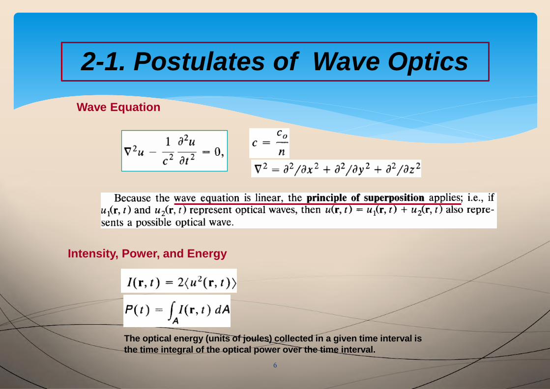
2-1. Postulates of Wave Optics
Wave Equation
Intensity, Power, and Energy
The optical energy (units of joules) collected in a given time interval is
the time integral of the optical power over the time interval.
6
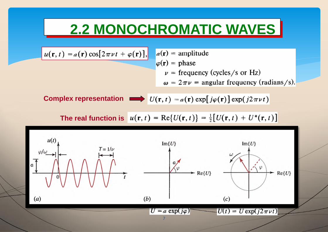
2.2 MONOCHROMATIC WAVES
7
2.2 MONOCHROMATIC WAVES
Complex representation
The real function is
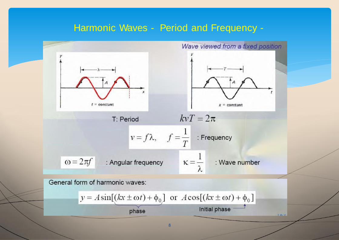
Harmonic Waves - Period and Frequency -
8
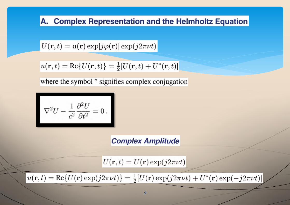
9
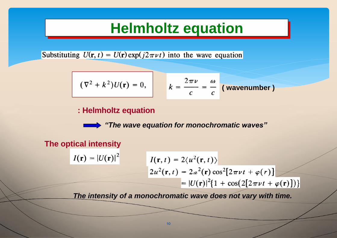
Helmholtz equation
10
Helmholtz equation
( wavenumber )
: Helmholtz equation
“The wave equation for monochromatic waves”
The optical intensity
The intensity of a monochromatic wave does not vary with time.
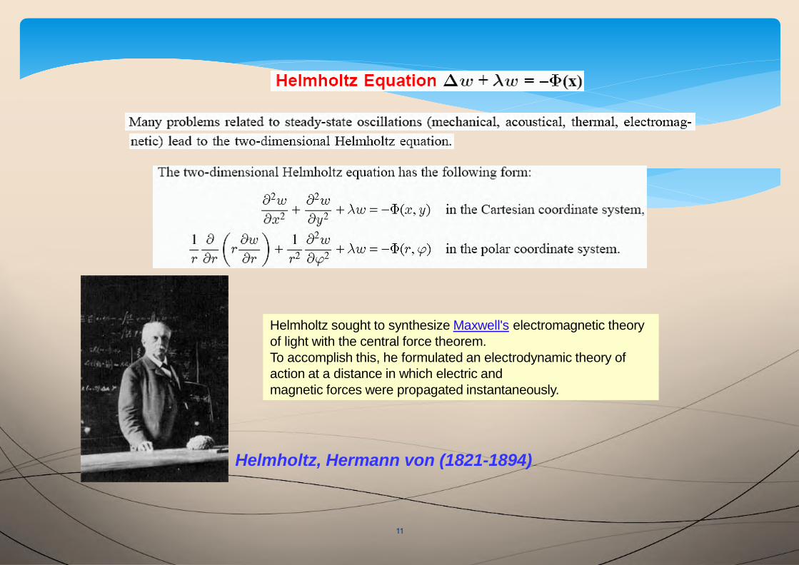
Helmholtz, Hermann von (1821-1894)
Helmholtz sought to synthesize Maxwell's electromagnetic theory
of light with the central force theorem.
To accomplish this, he formulated an electrodynamic theory of
action at a distance in which electric and
magnetic forces were propagated instantaneously.
11
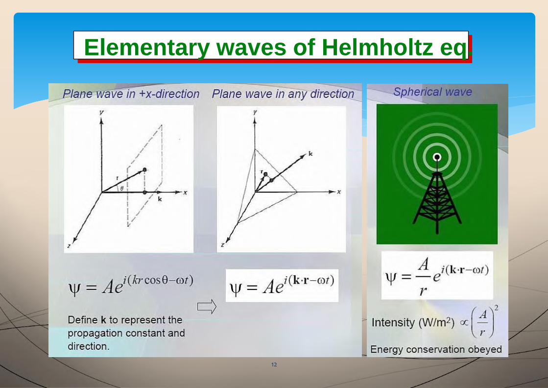
Elementary waves of Helmholtz eq.Elementary waves of Helmholtz eq.
12
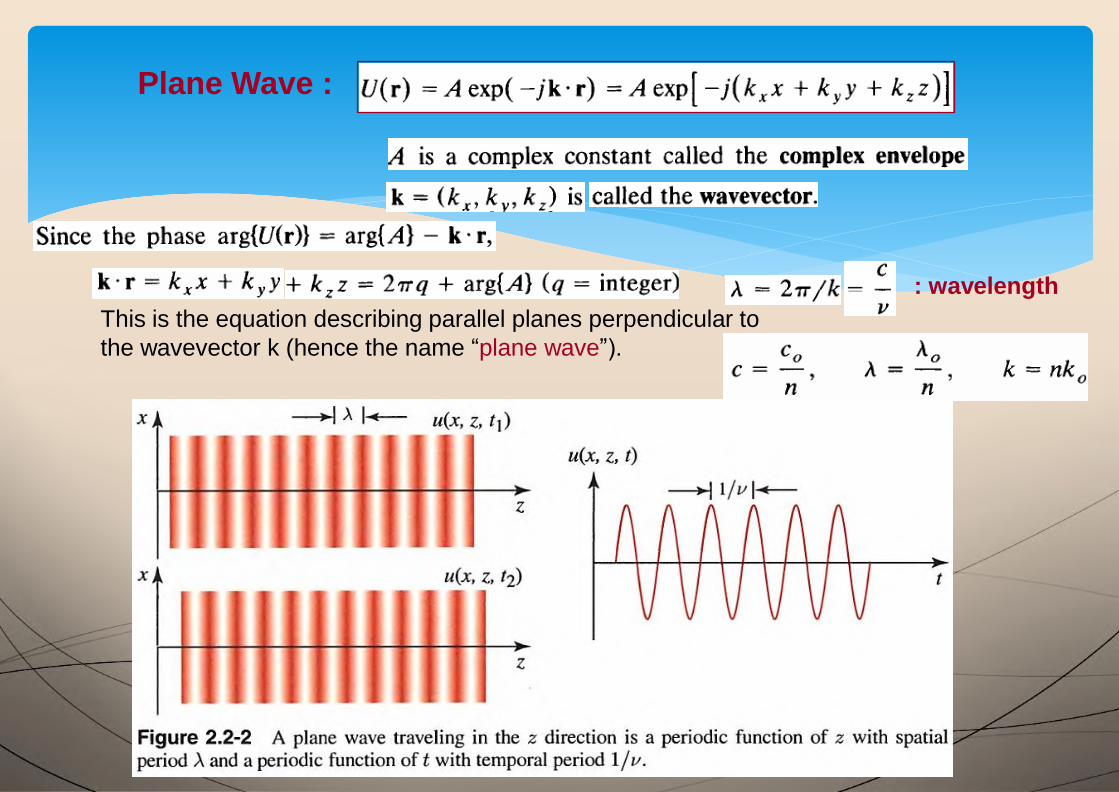
Plane Wave :
This is the equation describing parallel planes perpendicular to
the wavevector k (hence the name “plane wave”).
: wavelength
13
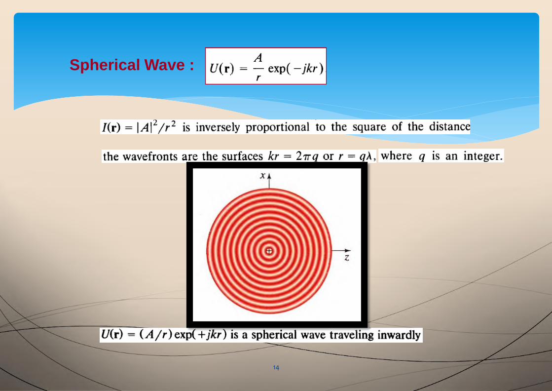
Spherical Wave :
14
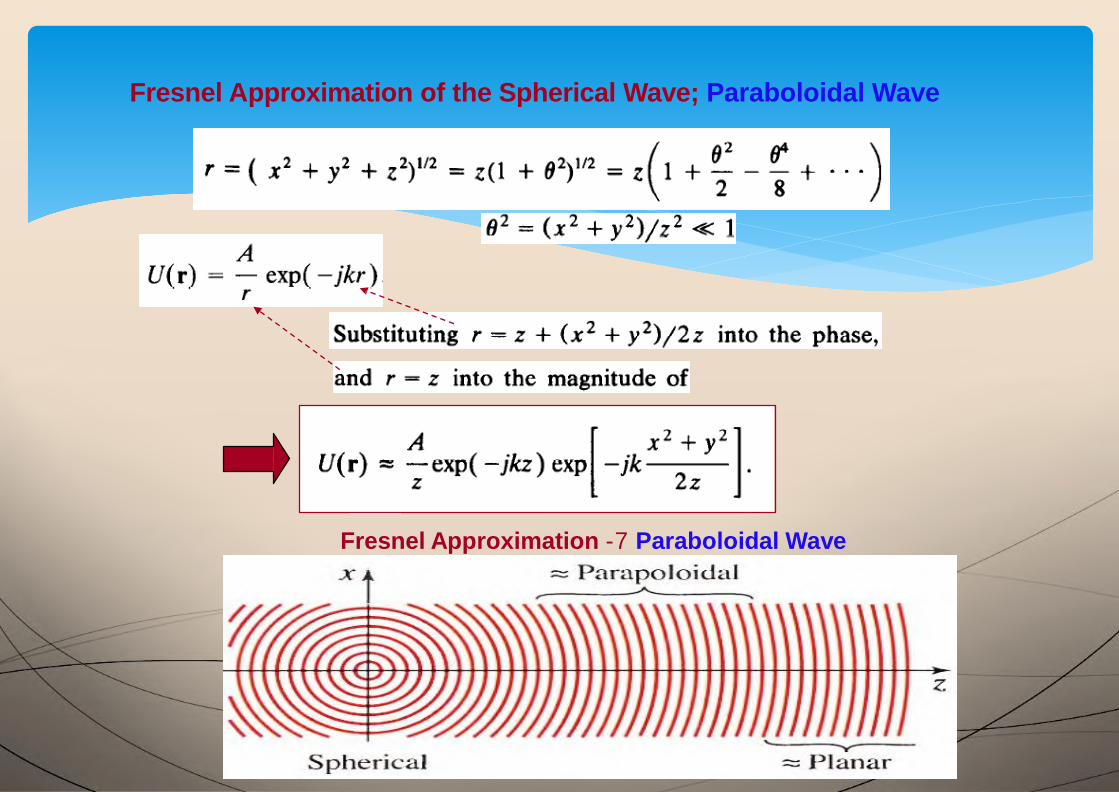
Fresnel Approximation of the Spherical Wave; Paraboloidal Wave
Fresnel Approximation -7 Paraboloidal Wave
15

Fresnel Approximation is valid when
(x2 + y2 ) = a2
16
Paraxial waves
17
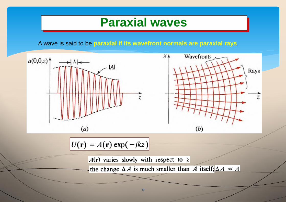
Paraxial waves
A wave is said to be paraxial if its wavefront normals are paraxial rays.
Paraxial Helmholtz equation
18
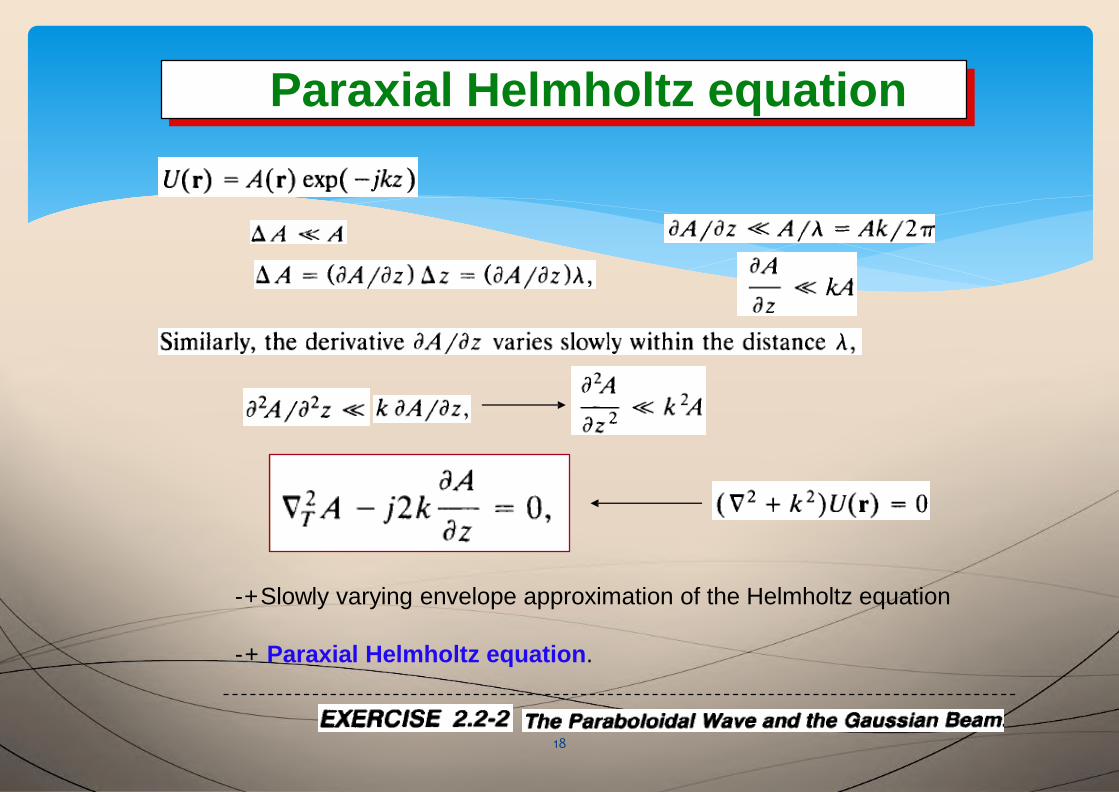
Paraxial Helmholtz equation
-+Slowly varying envelope approximation of the Helmholtz equation
-+ Paraxial Helmholtz equation.
Relation between wave optics and ray optics
19
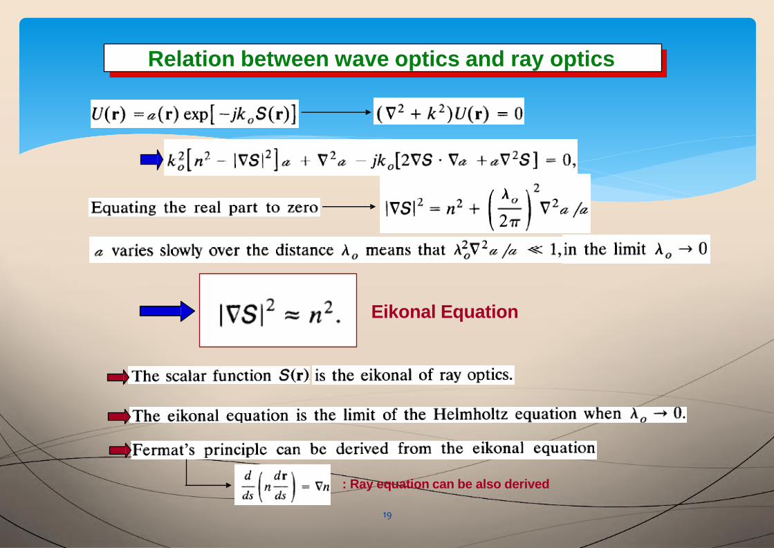
Relation between wave optics and ray optics
Eikonal Equation
: Ray equation can be also derived
2-4. Simple optical components
20
2-4. Simple optical components
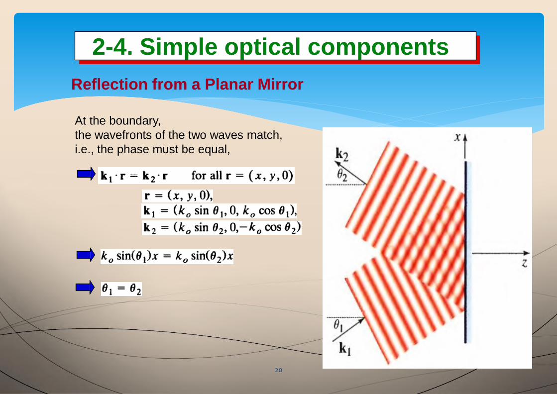
Reflection from a Planar Mirror
At the boundary,
the wavefronts of the two waves match,
i.e., the phase must be equal,
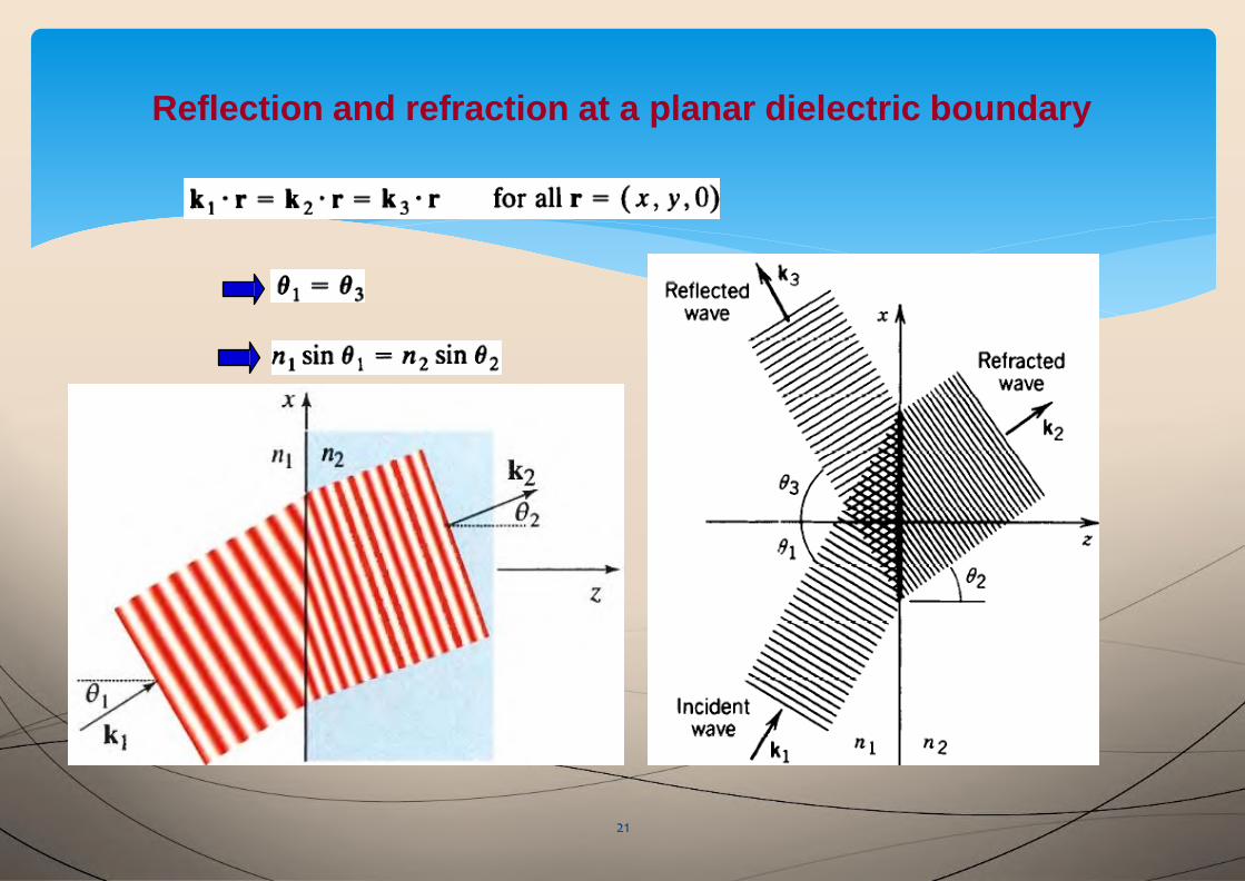
Reflection and refraction at a planar dielectric boundary
21
BOUNDARY CONDITIONS
22
BOUNDARY CONDITIONS
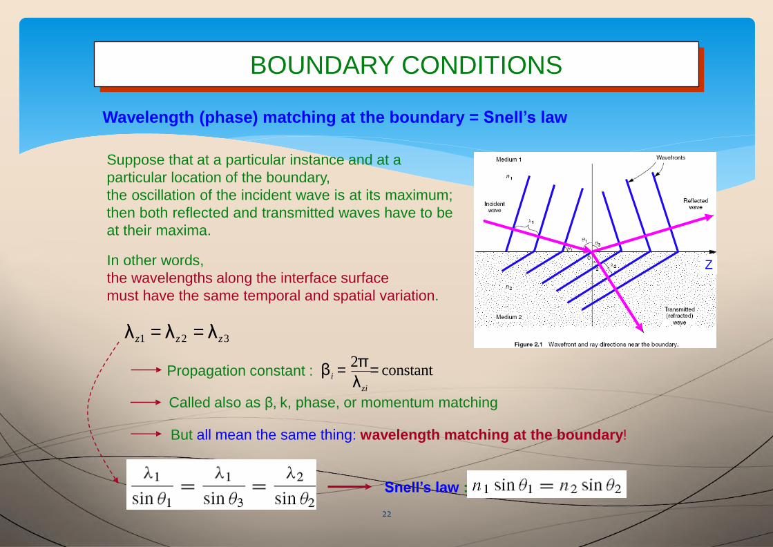
Called also as β, k, phase, or momentum matching
But all mean the same thing: wavelength matching at the boundary!
Snell’s law :
Wavelength (phase) matching at the boundary = Snell’s law
Suppose that at a particular instance and at a
particular location of the boundary,
the oscillation of the incident wave is at its maximum;
then both reflected and transmitted waves have to be
at their maxima.
In other words,
the wavelengths along the interface surface
must have the same temporal and spatial variation.
λz1 = λz2 = λz3
Propagation constant : β =2π
= constantzi
iλ
Z
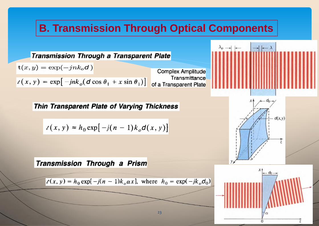
B. Transmission Through Optical Components
23

Thin Lens
24
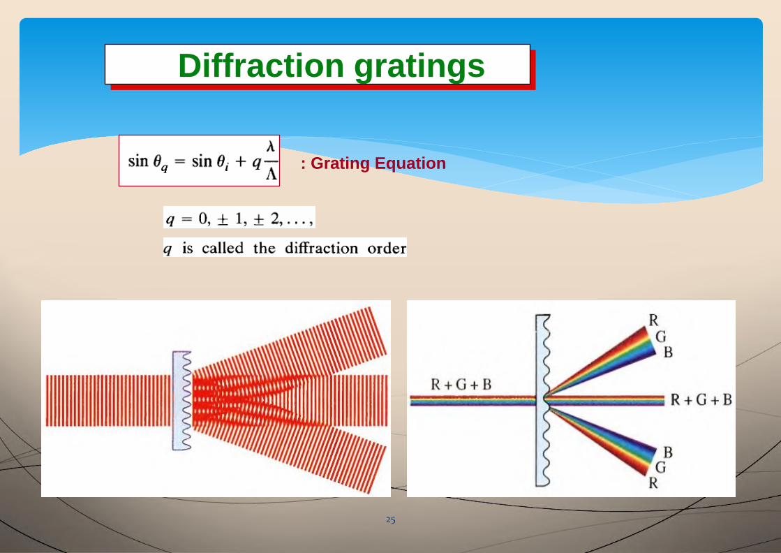
Diffraction gratings
25
Diffraction gratings
: Grating Equation
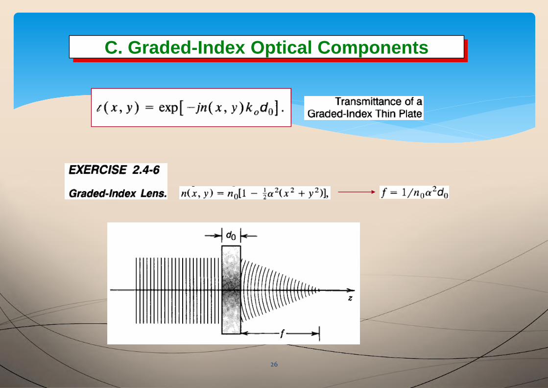
C. Graded-Index Optical ComponentsC. Graded-Index Optical Components
26
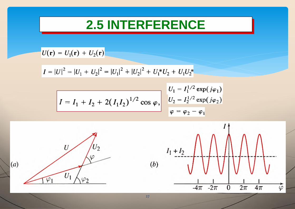
2.5 INTERFERENCE2.5 INTERFERENCE
27
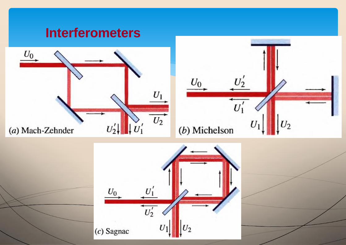
Interferometers
28
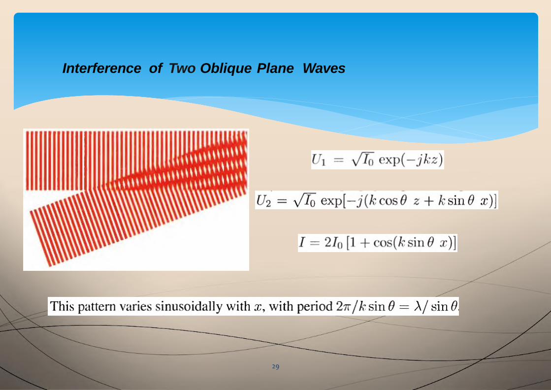
Interference of Two Oblique Plane Waves
29
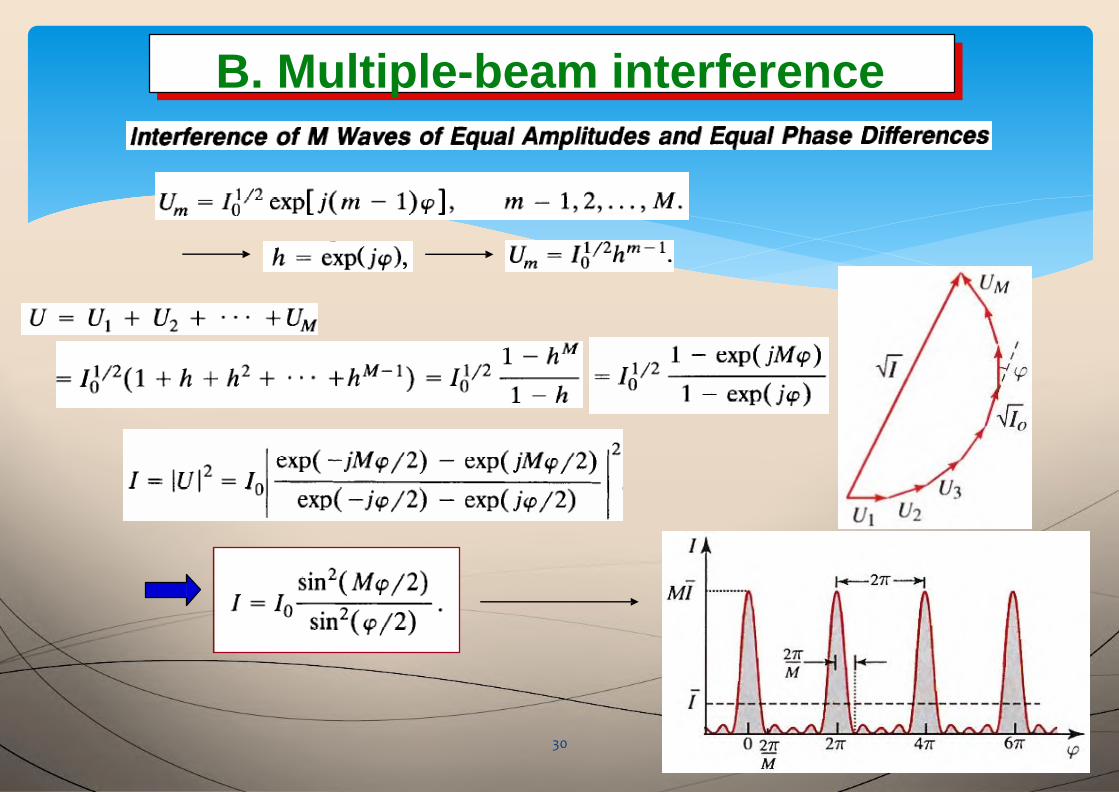
B. Multiple-beam interferenceB. Multiple-beam interference
30

: Finesse
31
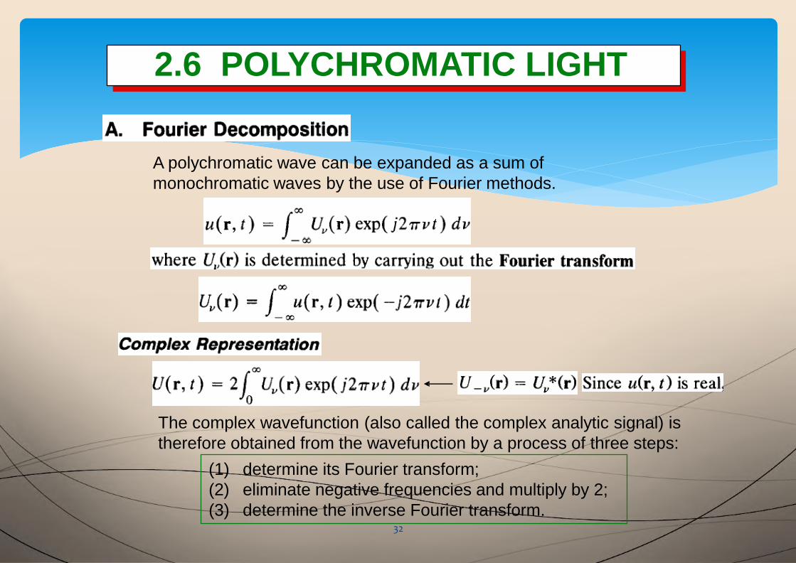
2.6 POLYCHROMATIC LIGHT2.6 POLYCHROMATIC LIGHT
A polychromatic wave can be expanded as a sum of
monochromatic waves by the use of Fourier methods.
The complex wavefunction (also called the complex analytic signal) is
therefore obtained from the wavefunction by a process of three steps:
(1) determine its Fourier transform;
(2) eliminate negative frequencies and multiply by 2;
(3) determine the inverse Fourier transform.32
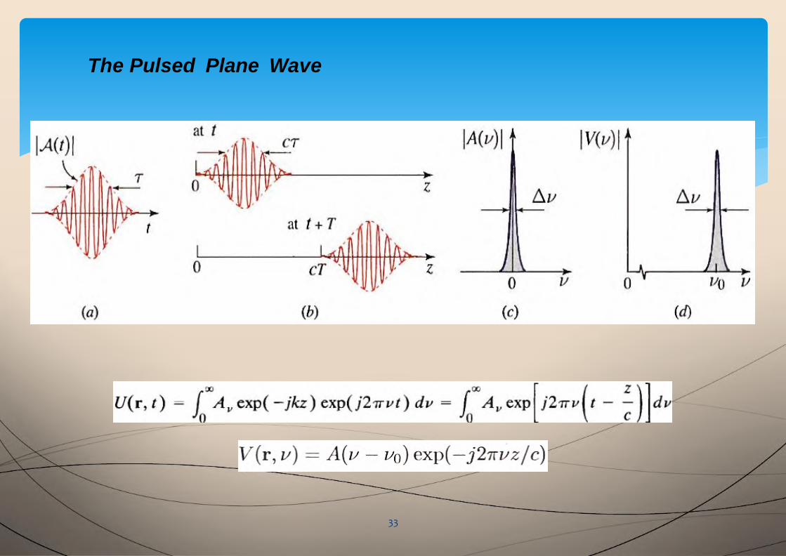
The Pulsed Plane Wave
33
34