Chapter 2 The ATLAS experiment
20
13 Chapter 2 The ATLAS experiment Contents 2.1 Introduction ..................................................................................................................... 13 2.2 Detector set-up ................................................................................................................. 13 2.2.1 Detector components .................................................................................................. 13 2.2.2 Particle identification .................................................................................................. 14 2.3 Magnet system ................................................................................................................. 15 2.4 Inner detector .................................................................................................................. 17 2.4.1 Introduction ................................................................................................................. 17 2.4.2 Precision tracker.......................................................................................................... 20 2.4.3 TRT ............................................................................................................................. 24 2.4.4 Radiation environment ................................................................................................ 26 2.4.5 Material ....................................................................................................................... 26 2.5 Calorimeter ...................................................................................................................... 27 2.6 Muon spectrometer ......................................................................................................... 28 2.6.1 Introduction ................................................................................................................. 28 2.6.2 Muon precision system ............................................................................................... 29 2.6.3 Muon trigger detector system...................................................................................... 31 2.7 References ........................................................................................................................ 32 2.1 Introduction This chapter describes the ATLAS experiment, which is one of the future LHC experiments. It is a so-called general-purpose experiment, studying all physics topics described in sec- tion 1.4. The global detector set-up is described in section 2.2. The ATLAS magnet system is de- scribed in section 2.3. Each detector component is described in a separate section: the inner detector is described in section 2.4, the calorimeter is described in section 2.5 and the muon spectrometer is finally described in section 2.6. The ATLAS trigger and data acquisition sys- tem will be described separately in chapter 5. 2.2 Detector set-up 2.2.1 Detector components The ATLAS detector (figure 2.1) has a layout that is typical for a collider detector and con- sists of two types of detector components: tracking detectors, which measure the position of a crossing charged particle with minimal disturbance, and calorimeters, which measure the energy of a particle by total absorption. From the collision point outwards first tracking de- tectors (inner detector) are placed, then calorimeters, divided in electromagnetic (em) and hadronic calorimeters, and then tracking detectors (muon spectrometer) again. The complete ATLAS detector is split into a barrel part, where detector layers are posi- tioned on cylindrical surfaces around the beam axis, and two end-cap parts, where detector
Transcript of Chapter 2 The ATLAS experiment

13
Chapter 2The ATLAS experiment
Contents
2.1 Introduction ..................................................................................................................... 13
2.2 Detector set-up................................................................................................................. 132.2.1 Detector components .................................................................................................. 132.2.2 Particle identification ..................................................................................................14
2.3 Magnet system ................................................................................................................. 15
2.4 Inner detector .................................................................................................................. 172.4.1 Introduction................................................................................................................. 172.4.2 Precision tracker.......................................................................................................... 202.4.3 TRT............................................................................................................................. 242.4.4 Radiation environment................................................................................................ 262.4.5 Material ....................................................................................................................... 26
2.5 Calorimeter ...................................................................................................................... 27
2.6 Muon spectrometer ......................................................................................................... 282.6.1 Introduction................................................................................................................. 282.6.2 Muon precision system ............................................................................................... 292.6.3 Muon trigger detector system...................................................................................... 31
2.7 References ........................................................................................................................ 32
2.1 IntroductionThis chapter describes the ATLAS experiment, which is one of the future LHC experiments.It is a so-called general-purpose experiment, studying all physics topics described in sec-tion 1.4.
The global detector set-up is described in section 2.2. The ATLAS magnet system is de-scribed in section 2.3. Each detector component is described in a separate section: the innerdetector is described in section 2.4, the calorimeter is described in section 2.5 and the muonspectrometer is finally described in section 2.6. The ATLAS trigger and data acquisition sys-tem will be described separately in chapter 5.
2.2 Detector set-up
2.2.1 Detector components
The ATLAS detector (figure 2.1) has a layout that is typical for a collider detector and con-sists of two types of detector components: tracking detectors, which measure the position ofa crossing charged particle with minimal disturbance, and calorimeters, which measure theenergy of a particle by total absorption. From the collision point outwards first tracking de-tectors (inner detector) are placed, then calorimeters, divided in electromagnetic (em) andhadronic calorimeters, and then tracking detectors (muon spectrometer) again.
The complete ATLAS detector is split into a barrel part, where detector layers are posi-tioned on cylindrical surfaces around the beam axis, and two end-cap parts, where detector

Chapter 2 The ATLAS experiment
14
layers are positioned in planes of constant z perpendicular to the beam pipe. The calorimeterconsists also of a forward1 and a backward part, extending up to a pseudorapidity of |η| = 4.9.The most important dimensions of the ATLAS detector are summarised in table 2.1.
Each detector component is optimised to satisfy various requirements, e.g. resolution withrespect to position and/or energy, particle identification, covered range, costs and material.
The inner detector and muon spectrometer are placed in a magnetic field for the measure-ment of the momentum of charged particles. This magnetic field causes a bending of thetrack, with a radius of curvature dependent on the momentum value.
ATLAS
S. C. Air CoreToroids
S. C. Solenoid
HadronCalorimeters
ForwardCalorimeters
MuonDetectors
InnerDetector
EM Calorimeters
Figure 2.1 Three-dimensional view of the ATLAS detector.
Table 2.1 Dimensions of the ATLAS sub-detectors.
component radius [m] length [m] η-coveragebarrel muon spectrometer 11 26 |η| < 1.4end-cap muon spectrometer 11 2.8 1.1 < |η| < 2.8barrel hadronic calorimeter 4.25 12.2 |η| < 1.0end-cap hadronic calorimeter 2.25 2.25 1.5 < |η| < 3.2barrel em-calorimeter 2.25 6.42 |η| < 1.4end-cap em-calorimeter 2.25 0.63 1.4 < |η| < 3.2forward/backward calorimeter integrated in end-cap 3.1 < |η| < 4.9barrel + end-cap inner detector 1.15 6.8 |η| < 2.4
2.2.2 Particle identification
Each particle gives a different signature in the ATLAS detector, making particle identifica-tion possible. The signatures for the most important particles are summarised in figure 2.2.
1 Throughout this thesis the term forward is also used for the end-cap part of the inner detec-tor at positive z (opposite side backward).

2.3 Magnet system
15
An electron gives a signal in the inner detector, losing a small part of its energy (see alsosection 2.4.5), and in the calorimeter (mainly in the electromagnetic calorimeter), depositingits remaining energy part. Photons give also a signal in the calorimeter, but not in the innerdetector (unless a photon converts into an electron-positron pair). Muons traverse the calo-rimeter and give a signal in the inner detector and muon spectrometer and eventually a smallsignal in the calorimeter. Charged hadrons give a signal in the inner detector and the calo-rimeters. Hadrons shower2 deeper into the calorimeter than electrons and photons and give asignal in both the electromagnetic and hadronic calorimeter. Jets (not shown in figure 2.2) area combination of hadronic and leptonic particles, and cause a signal in the inner detector andcalorimeters and eventually also in the muon spectrometer. Neutrinos can not be detected andleave only a signal of missing transverse energy, see also section 1.1.
Figure 2.2 Signature of some highly energetic particles in the inner detec-tor (inner tracker), calorimeter and muon spectrometer (outer tracker).
2.3 Magnet systemAn appropriate magnetic field distribution is required for measuring the transverse momentaof the produced charged particles. The magnet system of the ATLAS detector consists of foursuperconducting magnets:• A central solenoid [1]• An air-core barrel toroid [2]• Two air-core end-cap toroids [3]
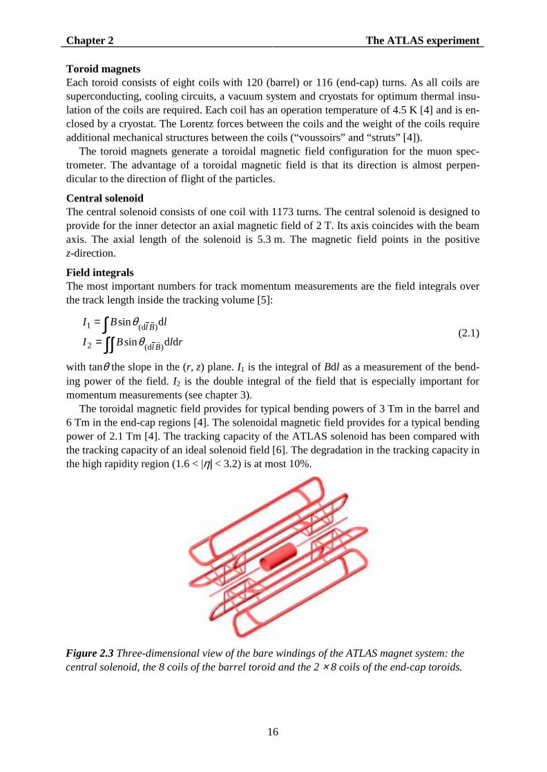
A three-dimensional view of the bare windings of the ATLAS magnet system is given infigure 2.3. In principle the three toroidal magnets could have been combined into a singlelarge toroidal magnet. For technical reasons the toroidal system is split into three sub-systems [4].
2 A shower is defined as the cascade production of electrons, photons and hadrons (forhadron showers) initiated by a highly energetic particle that was incident on a thick absorber.See also section 2.5.
Chapter 2 The ATLAS experiment
16
Toroid magnetsEach toroid consists of eight coils with 120 (barrel) or 116 (end-cap) turns. As all coils aresuperconducting, cooling circuits, a vacuum system and cryostats for optimum thermal insu-lation of the coils are required. Each coil has an operation temperature of 4.5 K [4] and is en-closed by a cryostat. The Lorentz forces between the coils and the weight of the coils requireadditional mechanical structures between the coils (“voussoirs” and “struts” [4]).
The toroid magnets generate a toroidal magnetic field configuration for the muon spec-trometer. The advantage of a toroidal magnetic field is that its direction is almost perpen-dicular to the direction of flight of the particles.
Central solenoidThe central solenoid consists of one coil with 1173 turns. The central solenoid is designed toprovide for the inner detector an axial magnetic field of 2 T. Its axis coincides with the beamaxis. The axial length of the solenoid is 5.3 m. The magnetic field points in the positivez-direction.
Field integralsThe most important numbers for track momentum measurements are the field integrals overthe track length inside the tracking volume [5]:
∫∫∫
=
=
rlBI
lBI
Bl
Bl
ddsin
dsin
)d(2
)d(1
rr
rr
θ
θ(2.1)
with tanθ the slope in the (r, z) plane. I1 is the integral of Bdl as a measurement of the bend-ing power of the field. I2 is the double integral of the field that is especially important formomentum measurements (see chapter 3).
The toroidal magnetic field provides for typical bending powers of 3 Tm in the barrel and6 Tm in the end-cap regions [4]. The solenoidal magnetic field provides for a typical bendingpower of 2.1 Tm [4]. The tracking capacity of the ATLAS solenoid has been compared withthe tracking capacity of an ideal solenoid field [6]. The degradation in the tracking capacity inthe high rapidity region (1.6 < |η| < 3.2) is at most 10%.
Figure 2.3 Three-dimensional view of the bare windings of the ATLAS magnet system: thecentral solenoid, the 8 coils of the barrel toroid and the 2 × 8 coils of the end-cap toroids.

2.4 Inner detector
17
2.4 Inner detector
2.4.1 Introduction
The inner detector is the part of the ATLAS detector placed the most close to the interactionpoint. The environment inside the electromagnetic calorimeter is very hostile: everything inthe inner cavity is subject to a high flux of pions, photons and neutrons. The pions and pho-tons are mostly created in the interaction point. The neutrons are due to backsplash from thecalorimeters.
A three-dimensional view of the inner detector is given in figure 2.4. The ATLAS innerdetector combines high-resolution detectors at inner radii with continuous tracking elementsat outer radii, all contained in a solenoid magnet with a central field of 2 T.
RequirementsThe ATLAS inner detector has been developed to satisfy various physics requirements on
electron identification, photon identification, identification of decaying 0SK mesons and the
reconstruction of secondary vertices due to the decay of particles containing bottom quarks.These requirements are described in more detail in the inner detector TDR (Technical DesignReport) [6]. They can be translated into requirements for the number of measurement points,the resolution of the measurement points, the covered range in η and r and track3 reconstruc-tion specifications. Also these requirements are described in more detail in the TDR [6]. Themomentum resolution requirement for a 500 GeV track varies between 30% and 50%, seealso chapter 3.
Detector set-upSilicon pixel detectors with the highest granularity are placed closest to the interaction point.Further away from the interaction point, silicon microstrip detectors (SCT, SemiConductorTracker) are placed. The total number of silicon precision layers must be limited because ofthe material they introduce, and because of their high cost. In the current design of theATLAS detector, a particle travelling from the interaction point crosses at least four strip lay-ers and three pixel layers. This is shown in figure 2.5, giving one hit for each pixel layer, andtwo for each strip layer (rφ and stereo measurement, see section 2.4.2).
The straw tube tracker (TRT, Transition Radiation Tracker) gives a much larger numberof tracking points (typically 36 points per track), however with less accuracy, and providesthe possibility of continuous track following with much less material per point and at lowercost. In figure 2.6 the number of crossed straws in the TRT is plotted.
The combination of the TRT and precision tracker makes a very robust track recognitionpossible and provides a high precision in (φ, r, z) co-ordinates. The relative precisions of thedifferent measurements (pixel detectors, SCT, TRT) are well matched, so that no singlemeasurement dominates the momentum resolution. This is important for reasons of robust-ness, in the event that a single system does not perform to its full specification.
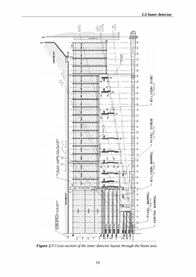
A cross-section of the engineering layout of the inner detector through the beam axis isgiven in figure 2.7. The outer radius of the inner detector is 115 cm. This value is a compro-mise between the best possible tracking capacity (equation (2.1)) and restrictions due to theinner dimension of the solenoid coil. The total length is 7 m, limited by the position of the
3 The trajectory of a charged particle through the magnetic field of the inner detector (ormuon spectrometer) is referred to as track.

Chapter 2 The ATLAS experiment
18
end-cap calorimetry. The precision trackers elements are contained within a radius of 56 cm,followed by the TRT, and finally the general support and service area at the outermost radius.
Forward SCT
Barrel SCT
TRT
Pixel DetectorsFigure 2.4 Three-dimensional view of the ATLAS inner detector.
0
5
10
0 1 2 3
|η|
Num
ber
Hits
SCT
Pixels
Figure 2.5 Number of hits per track in the pre-cision detectors. Taken from [6].
0
20
40
0 0.5 1 1.5 2 2.5
|η|
Num
ber
TR
T H
its
Figure 2.6 Number of hits per track in theTRT. Taken from [6].
2.4 Inner detector
19
Figure 2.7 Cross-section of the inner detector layout through the beam axis.

Chapter 2 The ATLAS experiment
20
2.4.2 Precision tracker
The precision tracker consists of pixel and microstrip detectors, both based on silicon tech-nology.
The pixel detector is designed to provide a set of very high-precision measurements asclose to the interaction point as possible. The system provides three of the precision meas-urements over the full acceptance, and determines the impact parameter resolution (seechapter 3) and hence the ability of the inner detector to find short-lived particles such as bot-tom quarks. The two-dimensional segmentation of the sensors requires the use of advancedelectronic techniques and interconnections for the readout. The readout chips of the pixelsensors are described in more detail in the TDR [7]. The total pixel system consists of1.4 × 108 detector elements.
The SCT (silicon microstrip detector) is designed to provide at least four of the precisionmeasurements per track in the intermediate radial range, and contributes to the measurementof transverse momentum, impact parameter and vertex position. The system is an order ofmagnitude larger in surface than previous generations of silicon microstrip detectors, and inaddition must face much higher radiation levels. The total SCT contains 61 m2 of silicon de-tectors, with 6.2 × 10⁶ readout channels.
Silicon detector operationSilicon detectors are based on the release of free charge by a particle traversing matter. Whena diode is biased in the reverse direction, there is only a small (dark) current. On the passageof a particle through the depleted region, electron-hole pairs are created, which results in abriefly enhanced conductivity of the depletion region. This gives rise to a peak in the electriccurrent through the detector.
Barrel pixel detectorIn the barrel area, the pixel layers are segmented in rφ and z. The pixel size is 50 µm in therφ-direction and 300 µm in the z-direction. The system consists of three layers at average ra-dii of about 4 cm, 11 cm and 14 cm. The innermost barrel layer is especially useful for bot-tom quark physics. For this reason, this layer is also referred to as B-layer. In figure 2.7 thislayer is referred to as vertex barrel.
The B-layer will need replacement after a few years at high luminosity, because radiationdamage will limit the lifetime of this layer. The exact time depends on the luminosity profile.It has not yet been decided whether the B-layer will be present during the whole lifetime ofthe inner detector, or only at the initial lower luminosity running.
The barrel pixel system is very modular, containing approximately 1500 identical detectormodules. Only one type of support structures is used. Each barrel module is 62.4 mm longand 22.4 mm wide, with about 6.1 × 105 pixel elements, readout by 16 chips each serving anarray of 24 by 160 pixels. The modules are overlapping in order to give hermetic coverage.Simulations show that the thickness of each layer is less than 1.39% of a radiation length [6].The most important characteristics of the barrel pixel system are summarised in table 2.2.
Table 2.2 Characteristics of barrel silicon pixel detector.
radius [mm] ò length ofcylinder [mm]
tilt angle[degrees]
row pitch[µm]
columnpitch [µm]
number ofmodules
47.5 387 10.5 50 300 260105.5 387 9.5 50 300 572137.5 387 9.5 50 300 754

2.4 Inner detector
21
End-cap pixel detectorThe end-cap pixel system consists on each side of the interaction point of four disks withmodules, placed between radii of 11 and 20 cm. These disks are located perpendicular to thebeam axis, using identical support structures. The pixels are segmented in rφ and r. The pixelsize is 50 µm in the rφ-direction and 300 µm in the r-direction. The total end-cap consists of1000 identical disk modules. The end-cap modules are very similar in design to the barrelmodules. The most important characteristics of the end-cap pixel system are given intable 2.3.
Table 2.3 Characteristics of end-cap silicon pixel detector.
z[mm]
inner radius[mm]
outer radius[mm]
row pitch[µm]
columnpitch [µm]
number ofmodules
490 107.1 196.0 50 300 140608 107.1 196.0 50 300 140759 107.1 196.0 50 300 1401035 151.0 196.0 50 300 80
Barrel SCTThe barrel part of the SCT consists of four cylindrical layers of modules, placed at radii of300, 373, 447 and 520 mm. Each module consists of four detectors. Each silicon detector is6.36 cm × 6.40 cm with 768 readout strips of 80 µm pitch. On each side of a module, twodetectors are bound together to form 12.8 cm long strips, with a 2 mm dead area in the mid-dle. Two such detector planes are glued together at a 40 mrad angle. This small stereo angleis used to obtain the z-measurement of the (φ, r, z) precision points. The configuration of abarrel SCT module is shown in figure 2.8, an expanded view is shown in figure 2.9. The sili-con detectors are glued to a central beryllia (BeO) baseboard and a heat spreader made ofpyrolytic graphite (TPG [7]). An important reason to use beryllia is its long radiation length,hence minimal disturbance of the track.
Modules are staggered in radius by ±1 mm to give overlap in z, and an overlap of 1% in φmakes the detector hermetic for tracks with a transverse momentum of more than 1 GeV. Themost important characteristics of the barrel SCT are given in table 2.4. A transverse view of aquadrant of the ATLAS barrel silicon layers is given in figure 2.10. The tilt angle made bythe modules and the staggered structure is clearly visible.

Chapter 2 The ATLAS experiment
22
Figure 2.8 Configuration of barrel SCT module.
Figure 2.9 Expanded view of a barrel module.

2.4 Inner detector
23
Table 2.4 Barrel SCT characteristics.
radius[mm]
ò lengthof cylinder [mm]
tilt angle[degrees]
pitch[µm]
strip length[mm]
number ofmodules
orientation4
300.0 746.7 10.0 80.0 126 12 × 32 φ,u373.0 746.7 10.0 80.0 126 12 × 40 φ,v447.0 746.7 10.0 80.0 126 12 × 48 φ,u520.0 746.7 10.0 80.0 126 12 × 56 φ,v
Figure 2.10 Transverse view of the ATLAS barrel precision layers (SCT + pixel detector).
End-cap SCTThe end-cap modules are very similar in construction but use tapered strips, with one setaligned radially, and the other with a 40 mrad stereo angle α. End-cap modules are made intwo versions with lengths of about 12 and 7 cm. The 12 cm strips consist of two parts, with a2 mm dead area in the middle. The layout of an end-cap module is shown in figure 2.11, anexpanded view is shown in figure 2.12. The end-cap modules are mounted in up to threerings onto nine wheels, which are interconnected by a space frame. The most important char-acteristics of the end-cap part are given in table 2.5.
4 The “u-layer” makes a positive stereo angle α of +40 mrad. The “v-layer” makes an angle αof –40 mrad with the z-direction. The “u/v-layer” is also referred to as “stereo-layer”. The“φ-layer” is placed parallel to the z-direction.

Chapter 2 The ATLAS experiment
24
Figure 2.11 End-cap module layout.Figure 2.12 Expanded view of an end-capmodule.
Table 2.5 End-cap SCT characteristics.
z[mm]
radius (i/o)[mm]
# modules[i/m/o]
strip length(i/m/o)[mm]
inner strippitch
(i/m/o) [µm]
outer strippitch
(i/m/o) [µm]
orienta-tion
835 259-560 40/40/52 72/117/121 54/70/71 70/95/90 φ,u925 336-560 -/40/52 -/117/121 -/70/71 -/95/90 φ,v1072 259-560 40/40/52 72/117/121 54/70/71 70/95/90 φ,u1260 259-560 40/40/52 72/117/121 54/70/71 70/95/90 φ,v1460 259-560 40/40/52 72/117/121 54/70/71 70/95/90 φ,u1695 259-560 40/40/52 72/117/121 54/70/71 70/95/90 φ,v2135 336-560 -/40/52 -/117/121 -/70/71 -/95/90 φ,u2528 401-560 -/40/52 -/72/121 -/54/71 -/70/90 φ,v2788 440-560 -/-/52 -/-/121 -/-/71 -/-/90 φ,u
2.4.3 TRT
The TRT (Transition Radiation Tracker) contributes to the transverse momentum measure-ment. The larger number of measurements and the higher average radius compensate thelower precision per point of the TRT compared to the precision tracker. The TRT is not usedfor impact parameter measurements (see chapter 3).
The TRT is based on the use of straw detectors, which can operate at the required veryhigh rates by virtue of their small diameter and the isolation of the sense wires within indi-vidual gas envelopes. This technique is intrinsically radiation hard, and allows a large number

2.4 Inner detector
25
of measurements to be made on every track at modest cost. However the detector must copewith a large occupancy and high counting rate at the LHC design luminosity. At this lumi-nosity, the measurement accuracy, averaged over all straws, is better than 50 µm, includingerrors from alignment [7]. A schematic view of the TRT detector in the (r, z) plane, togetherwith the main dimensions is given in figure 2.13.
Straw tube operationA straw tube is a thin cylindrical tube with a conducting inner surface at negative potential. Awire is strung in its centre, which is held at positive voltage. The straws are filled with xenongas. The distance of a traversing particle from the anode wire can be derived from the arrivaltime of the signal on the anode (drift time measurements). Electron identification capabilityis added by conversion in the xenon gas of transition-radiation photons, created in thinfoils between the straws. The creation of transition-radiation photons is based on the follow-ing mechanism: when a charged particle with energy E and mass m crosses a transition of twomaterials with a different dielectric constant, it has a probability proportional of γ = E/m toemit photons in the keV range. This effect is most pronounced for electrons due to their highγ-factor.
Each straw is 4 mm in diameter, giving a fast electrical response and good mechanicalproperties for a maximum straw length of 150 cm. With each straw a measurement of thedrift time and amplitude is possible. The drift time measurement corresponds to a spatialresolution of 170 µm per straw. The use of two independent amplitude thresholds allows thedetector to discriminate between hits without accompanying transition radiation hits, whichpass the lower threshold, and hits with accompanying transition radiation hits, which pass thehigher.
Barrel TRTThe barrel section is built of individual modules with between 329 and 793 axial straws each(parallel to the beam direction), covering the radial range from 56 to 107 cm. The total num-ber of straws in the barrel is about 5 × 10⁴. Each straw is divided into two at the centre in or-der to reduce the occupancy and is read out at each end.
End-cap TRTOne end-cap part consists of 18 wheels with radial straws. The 14 wheels nearest to the inter-action point cover the radial range from 64 to 130 cm. The last four wheels extend to an innerradius of 48 cm. This is necessary to maintain a constant number of crossed straws over thefull acceptance. The wheels 7 to 14 have half as many straws per cm in z as the other wheels.The total number of straws in the end-cap part is about 3.2 × 10⁵. Each straw is readout at theouter radius.

Chapter 2 The ATLAS experiment
26
Figure 2.13 Schematic view of the TRT detector in the (r, z) plane, together with the maindimensions.
2.4.4 Radiation environment
The radiation levels in the inner detector cavity will be extremely high, leading to damage inthe silicon detectors, degradation of the electronics performance and contribution of back-ground hits in the sensitive elements. The large |η| coverage required in the very small avail-able volume makes it necessary to install the detector components close to the beam axis.
The most relevant quantity for the damage in silicon detectors is the fluence expressed interms of 1 MeV equivalent neutrons. The typical values vary between 1.5 × 1013 cm-2/year forthe SCT to 5 × 1013 cm-2/year for the pixel detector [6]. All materials used in the inner de-tector cavity must be qualified to survive the doses and fluxes expected at the positions atwhich they are placed.
The precision tracker is operated at low temperature because the effect of silicon radiationdamage is strongly temperature dependent. As nominal operating temperature has been cho-sen -5 Û&�WR�-10 Û&��-7 Û&�DYHUDJH�LQ�WKH�6&7���:LWK�WKLV�RSHUDWLQJ�WHPSHUDWXUH�WKH�SUHFLVLRQtracker will survive an operation of ten years at high luminosity. This low temperature alsohas the beneficial effect of reducing the leakage current and hence heat-generation inside thedetector substrate. The entire silicon system will be enclosed in a cold envelope, with an ac-tive shield preventing heat transfer from the TRT.
All the electronics in the inner detector cavity will be purchased from vendors using rec-ognised radiation-hard chip fabrication processes.
2.4.5 Material
Tracking detectors must cause the smallest possible disturbance of the tracks passing throughit. This means that the amount of material in the inner detector must be as minimal as possi-ble. There are however several boundary conditions which cause that the amount of materialin the ATLAS detector will be much larger than that of previous tracking detectors. This ismostly due to the necessity of using radiation hard components and the necessity of installingall the front-end electronics components on the detector itself.

2.5 Calorimeter
27
The cumulative distributions for the number of radiation lengths for the pixel detector,SCT, TRT and the services5 are shown in figure 2.14. The corresponding distributions for theabsorption length are given in figure 2.15. From these distributions it follows that the amountof material in the inner detector is significant, especially in the transition region between bar-rel and end-cap. This large amount of material makes it much more difficult for the calo-rimeter to do a correct energy reconstruction. The consequences are described in the calo-rimeter performance TDR [8]. For the inner detector the consequences are also important:• Tracks undergo significant multiple scattering• There is a significant increase in multiplicity due to secondary interactions• Electrons have a significant bremsstrahlung probability• Photons have a significant probability to convert into an electron-positron pair• Absorption of hadrons, causing tracks to be lostThe consequences for the inner detector are described in more detail in the inner detectorTDR [6]. The influence of multiple scattering on the detector resolution is described in moredetail in chapter 3.
0
0.2
0.4
0.6
0.8
1
1.2
1.4
0 0.5 1 1.5 2 2.5 3 3.5
|η|
Rad
iatio
n le
ngth
Pixel
SCT
TRT
Total
Figure 2.14 Cumulative distribution for num-ber of radiation lengths for (a) pixel detector,(b) SCT, (c) TRT and (d) external services.Taken from [6].
0
0.1
0.2
0.3
0.4
0.5
0 0.5 1 1.5 2 2.5 3 3.5
|η|
Abs
orpt
ion
leng
th
Pixel
SCT
TRT
Total
Figure 2.15 Cumulative distribution for num-ber of absorption lengths for (a) pixel detector,(b) SCT, (c) TRT and (d) external services.Taken from [6].
2.5 CalorimeterThe calorimeters are placed between the inner detector and the muon spectrometer. The pri-mary goal of the calorimeters is the energy measurement of electrons, photons and jets, andthe measurement of the missing transverse energy. The calorimeters however also provideposition and angular measurements and particle identification. Their radiation resistance mustallow operation for more than ten years of data-taken at high luminosity.
The principle of calorimetry is the energy measurement of an incident particle by total ab-sorption, where a fraction of the total energy is transformed into a measurable quantity(charge or light). An incident electron or photon gives rise to an electromagnetic shower that
5 Detector elements like cables, cooling pipes, support structures etc. are referred to as serv-ices.
Chapter 2 The ATLAS experiment
28
can be described by a cascade of e± and γ production (mainly bremsstrahlung and the creationof e+e- pairs). An incident hadron gives rise to a hadronic shower consisting of an electro-magnetic component (e±, γ), a hadronic component of strongly interacting particles and acomponent of low energetic particles that are not detected. Particle identification is per-formed using both the electromagnetic and hadronic calorimeters on the basis of transversaland longitudinal shower profiles. An electromagnetic shower gives mainly a signal in the firstpart of the calorimeter (electromagnetic calorimeter). A hadron gives a signal in both parts ofthe calorimeter.
Because of the special interest in photons and electrons the resolution of the electromag-netic calorimeter is of prime importance. The hadron calorimeters are less accurate, which isalso partly due to the nature of hadronic showers in the calorimeter. The design goal energyresolution for photons and electrons is [8]:
EEEE 3.0
01.01.0 ⊕⊕=
σ(2.2)
with E in GeV. The design goal energy resolution for hadrons is:
03.05.0 ⊕=EE
Eσ(2.3)
All calorimeters consist of three parts, a barrel part, an end-cap part and a for-ward/backward part. The forward/backward calorimeter extends to |η| = 4.9. This is needed toidentify events with missing transverse energy, e.g. SUSY events (chapter 4). Both thehadronic and electromagnetic forward calorimeters are liquid argon based and are integratedin the cryostats of the end-cap calorimeters. The barrel and extended barrel region of thehadron calorimetry use iron plates with scintillation plates. In the end-cap-region the hadroncalorimeter is based on liquid argon. All electromagnetic calorimetry is based on liquid argonand lead absorbers [9, 10].
To make position measurements possible, the calorimeters are segmented in cells. Theelectromagnetic calorimeter uses a segmentation varying between ∆η × ∆φ = 0.003 × 0.1 and∆η × ∆φ = 0.025 × 0.025. The hadronic calorimeter uses a coarser segmentation of∆η × ∆φ = 0.1 × 0.1.
Other particles than primary muons that are not stopped in the calorimeter give rise to abackground signal in the muon spectrometer. The thickness of the electromagnetic calorime-ter is about 25-30 radiation lengths. The thickness of the hadronic calorimeter is about 10 ab-sorption lengths [11].
2.6 Muon spectrometer
2.6.1 Introduction
The outermost part of the ATLAS detector is a muon spectrometer. The task of the muonsystem is to reconstruct the momentum and direction of flight of muon tracks with the high-est possible resolution. The other particles (except the neutrinos and possibly the SUSY LSP(chapter 4)) are already stopped in the calorimeters.
Primary particles that are not stopped in the calorimeter and penetrate into the muon spec-trometer give rise to a background signal (primary background). Another source of back-grounds are neutrons and photons in the MeV range, produced by secondary interactions in

2.6 Muon spectrometer
29
the calorimeters, shielding material, the beam pipe and machine elements (radiation back-ground).
The muon detector system has approximately 1.3 × 10⁶ readout channels (including thetrigger chambers, see below). As described in section 2.3, the muon spectrometer is situatedin a toroidal magnetic field with a typical bending power of 3 Tm for the barrel and 6 Tm forthe end-cap. The momentum resolution for 1 TeV muons varies between 10% and 20%(chapter 3).
2.6.2 Muon precision system
The muon spectrometer is divided in a barrel and two end-cap parts. The barrel extends up toa pseudorapidity of |η| ≈ 1. The end-cap chambers cover the pseudorapidity range of|η| = 1 - 2.7. A side view of one quadrant of the muon spectrometer is given in figure 2.16.
Figure 2.16 Cross-section of one quadrant of the muon spectrometer.
BarrelIn the barrel region, cylindrical layers around the beam axis are used. A transverse view ofthe barrel part of the muon spectrometer is given in figure 2.17. In the transverse plane, themuon detector is divided in eight towers with large detection stations and eight towers withsmall stations. A tower contains in general three layers of measurement stations to locate themuon so that the curvature of its trajectory in the magnetic field can be determined. This re-sults in knowledge of both direction and momentum of the particle. Due to the presence ofsupport structures, two small towers contain only two detection layers.
Each measurement station consist of two separated half stations. Each half station consistsof three or four layers of detection elements. The detection elements are monitored drifttubes, described below. Optical alignment systems have been designed to meet the stringentrequirements on the mechanical accuracy and the survey of the precision chambers.
End-capEach end-cap part consists of four rings with detectors, concentric with the beam axis, atabout 7.5, 10, 14 and 21-23 m distance from the interaction point. Monitored drift tubes areused for the precision measurement in the end-caps over most of the area. At large pseudora-

Chapter 2 The ATLAS experiment
30
pidity (|η| = 2-2.7), cathode strip chambers are used due to the demanding rate and back-ground conditions.
The chamber planes are orthogonal to the beam axis with the drift tubes oriented in theazimuthal direction. Viewed along the beam pipe the chambers are of trapezoidal shape. Theyare arranged with the same 16-fold azimuthal segmentation as in the barrel, with large andsmall chambers covering the same azimuthal range as the barrel chambers (figure 2.18).
ATLAS
Precision chambersTrigger chambers
Muon Spectrometer
End-cap toroid
Barrelcoils
Figure 2.17 Transverse view of the ATLAS muon spectrometer in the underground hall.
Figure 2.18 The end-cap wheel placed at 14 m with the MDT chambers arranged in 16 sec-tors with small and large chambers alternating. The barrel chamber towers are indicated.

2.6 Muon spectrometer
31
MDT operationPressurised MDT (Monitored Drift Tube) chambers combine high intrinsic spatial resolutionwith an internal monitoring system to observe internal deformations of the chamber. Theyprovide for a robust, cost-effective instrumentation suitable for mass production. The basicdetection element of an MDT is a cylindrical aluminium drift tube of 30 mm diameter and acentral wire of 50 µm diameter at 3270 V with respect to the tube [12]. The detector is oper-ated with a non-flammable gas mixture at 3 bar absolute pressure for reduced diffusion andionisation fluctuation [12]. There is a linear relation between the drift time and drift distance.
A schematic drawing of a barrel MDT chamber is given in figure 2.19. The chambers forthe end-cap are of trapezoidal shape, but are of similar design otherwise. The average singletube resolution has a value of 80 µm [12].
Figure 2.19 Schematic drawing of a rectangular MDT chamber constructed frommultilayers of three monolayers each, for installation in the barrel spectrometer.
CSC operationCSCs (Cathode Strip Chambers) are multiwire proportional chambers with wires on a highvoltage strung parallel in a gas volume, closed by conducting planes at 0 V. One of the twoenclosing planes is appropriately segmented in strips with a readout pitch of 5 mm. The CSCshave a symmetric cell in which the anode-conducting plane distance equals the anode wirespacing. The anode wire spacing has now been fixed at 2.54 mm, which is considerably lowerthan the tube radius of the MDTs to reduce the occupancy per wire. Precise position-measurements along the wires are achieved by determining the centre of gravity of the chargeinduced on the strips of one of the two conducting planes. With prototypes, resolutions ofbetter than 50 µm have been achieved in test beams [12].
2.6.3 Muon trigger detector system
The muon spectrometer plays an important role in the ATLAS trigger system (chapter 5). Themuon trigger system covers the pseudorapidity range |η| ≤ 2.4. The muon trigger system mustallow for the online reconstruction of muon tracks above 6 GeV and 20 GeV (transversemomentum) at the bunch-crossing frequency of 40 MHz.
The muon trigger detector system consists of dedicated and fast chambers especially de-veloped for trigger purposes, which are independent from the MDT/CSC chambers and havea low occupancy. The MDTs and CSCs can not be used in the trigger system because these

Chapter 2 The ATLAS experiment
32
chambers will have too long drift times, which can be much longer than the LHC bunch-crossing period of 25 ns.
A system of RPCs (Resistive Plate Chambers) provide trigger signals in the barrel region.The trigger detector in the barrel is made up of three stations, each with two detection layers.They are located on both sides of the middle MDT station, and either directly above or di-rectly below the outer MDT station. The two stations near the centre provide the low-pT trig-ger (pT > 6 GeV). The third station, at the outer radius of the magnet, allows to increase the pT
threshold to 20 GeV, for the high-pT trigger. An RPC is a gaseous parallel-plate detector witha typical spatial resolution of the order of 1 cm and a typical time resolution of the order of1 ns. A detailed description of the RPCs is given in the muon spectrometer TDR [12].
TGCs (Thin Gap Chambers) provide trigger capabilities in the end-cap region. Seven lay-ers of TGCs complement the middle MDT station. Two layers of TGCs complement the in-ner MDT station. TGCs are standard multiwire proportional chambers [12], but with smallanode-to-anode, (wire-to-wire) distance (1.8 mm) and small cathode-to-anode distance(1.4 mm). The spatial and time resolution of TGCs is similar to RPCs.
2.7 References1. ATLAS Magnet Project Collaboration, ATLAS Central Solenoid Technical Design Re-
port, ATLAS TDR-9, CERN/LHCC 97-21 (1997).
2. ATLAS Magnet Project Collaboration, ATLAS Barrel Toroid Technical Design Report,ATLAS TDR-7, CERN/LHCC 97-19 (1997).
3. ATLAS Magnet Project Collaboration, ATLAS End-cap Toroids Technical Design Re-port, ATLAS TDR-8, CERN/LHCC 97-20 (1997).
4. ATLAS Magnet Project Collaboration, ATLAS Magnet System Technical Design Report,ATLAS TDR-6, CERN/LHCC 97-18 (1997).
5. V.I. Klyukhin, A. Poppleton and J. Schmitz, Field Integrals for the ATLAS Tracking Vol-ume, ATLAS INDET-NO-023 (1993).
6. ATLAS Inner Detector Community, ATLAS Inner Detector Technical Design ReportVolume 1, ATLAS TDR-4, CERN/LHCC 97-16 (1997).
7. ATLAS Inner Detector Community, ATLAS Inner Detector Technical Design ReportVolume 2, ATLAS TDR-5, CERN/LHCC 97-17 (1997).
8. ATLAS Calorimeter Community, ATLAS Calorimeter Performance Technical DesignReport, CERN/LHCC 94-40 (1996).
9. ATLAS Calorimeter Community, ATLAS Tile Calorimeter Technical Design Report,ATLAS TDR-3, CERN/LHCC 96-42 (1996).
10. ATLAS Calorimeter Community, ATLAS Liquid Argon Calorimeter Technical DesignReport, ATLAS TDR-2, CERN/LHCC 96-41 (1996).
11. ATLAS Collaboration, ATLAS Technical Proposal for a General Purpose pp Experimentat the Large Hadron Collider at CERN, CERN/LHCC 94-43, LHCC-P2 (1994).
12. ATLAS Muon Collaboration, ATLAS Muon Spectrometer Technical Design Report,ATLAS TDR-10, CERN/LHCC 97-22 (1997).
13. D. Fourier and L. Serin, Notes on Lecture Series Experimental Techniques.