
CHAPTER 2: PROPOSED ACTION AND ALTERNATIVES 2.1 INTRODUCTION 2.pdf · Kittitas Valley Wind Power...
54
Kittitas Valley Wind Power Project Chapter 2: Proposed Action and Alternatives Draft EIS 2-1 December 2003 CHAPTER 2: PROPOSED ACTION AND ALTERNATIVES 2.1 INTRODUCTION This chapter presents information concerning the Applicant; describes the Applicant’s proposal, including the project location, project facilities, safety features and control systems, and construction, operations and maintenance, and decommissioning activities; describes the costs for the project; identifies mitigation measures inherent in the design; describes the No Action Alternative; and discusses alternatives considered by the Applicant but eliminated from detailed evaluation. The information presented in this section is primarily based on information provided by the Applicant in the ASC (Sagebrush Power Partners LLC 2003a, Sections 2.1, 2.3, 2.4, 2.12, 2.14, 2.16, and 9.1). Where additional information has been used to evaluate the potential impacts associated with the proposal, that information has been referenced. Rules published under the SEPA require that this EIS describe the proposal and alternative courses of action. Reasonable alternatives include actions that could feasibly attain or approximate a proposal’s objectives, but at a lower environmental cost or decreased level of environmental degradation. The rules also require that the impacts of these alternatives be compared with the impacts of not implementing the alternatives (No Action) and that the advantages and disadvantages of delaying the approval for some future date be discussed. As this chapter explains, alternative wind energy technologies, alternative project sites, and an alternative project layout were considered in developing and siting the wind turbine towers. These alternatives, however, were eliminated from further study because they either did not meet the proposal’s objectives, were not practical or feasible, or would result in higher environmental costs (compared to the proposed action). Therefore, this EIS evaluates the potential impacts of the Kittitas Valley Wind Power Project and its associated facilities (the proposed action), as described in this chapter, and the No Action Alternative. 2.1.1 The Applicant The Applicant for the Kittitas Valley Wind Power Project is Sagebrush Power Partners LLC, a wholly owned subsidiary of Zilkha Renewable Energy. A partial list of other wind power projects developed, under construction, or planned in the near term by Zilkha Renewable Energy include the following (Taylor, pers. comm., 2003): Blue Canyon Wind Farm, Oklahoma (75 MW) Zilkha Renewable Energy is in the process of building the 75-MW Blue Canyon wind project near Lawton, Oklahoma. The project is scheduled to be on-line by December of 2003. Zilkha will serve as the operations manager at Blue Canyon during the operational phase of the project. Energy is being sold under a long-term power purchase agreement (PPA) to Western Farmers Electric Cooperative of Andarko, Oklahoma.
Transcript of CHAPTER 2: PROPOSED ACTION AND ALTERNATIVES 2.1 INTRODUCTION 2.pdf · Kittitas Valley Wind Power...

Kittitas Valley Wind Power Project Chapter 2: Proposed Action and AlternativesDraft EIS 2-1 December 2003
CHAPTER 2: PROPOSED ACTION AND ALTERNATIVES
2.1 INTRODUCTION
This chapter presents information concerning the Applicant; describes the Applicant’s proposal,including the project location, project facilities, safety features and control systems, andconstruction, operations and maintenance, and decommissioning activities; describes the costsfor the project; identifies mitigation measures inherent in the design; describes the No ActionAlternative; and discusses alternatives considered by the Applicant but eliminated from detailedevaluation. The information presented in this section is primarily based on information providedby the Applicant in the ASC (Sagebrush Power Partners LLC 2003a, Sections 2.1, 2.3, 2.4, 2.12,2.14, 2.16, and 9.1). Where additional information has been used to evaluate the potentialimpacts associated with the proposal, that information has been referenced.
Rules published under the SEPA require that this EIS describe the proposal and alternativecourses of action. Reasonable alternatives include actions that could feasibly attain orapproximate a proposal’s objectives, but at a lower environmental cost or decreased level ofenvironmental degradation. The rules also require that the impacts of these alternatives becompared with the impacts of not implementing the alternatives (No Action) and that theadvantages and disadvantages of delaying the approval for some future date be discussed. As thischapter explains, alternative wind energy technologies, alternative project sites, and analternative project layout were considered in developing and siting the wind turbine towers.These alternatives, however, were eliminated from further study because they either did not meetthe proposal’s objectives, were not practical or feasible, or would result in higher environmentalcosts (compared to the proposed action). Therefore, this EIS evaluates the potential impacts ofthe Kittitas Valley Wind Power Project and its associated facilities (the proposed action), asdescribed in this chapter, and the No Action Alternative.
2.1.1 The Applicant
The Applicant for the Kittitas Valley Wind Power Project is Sagebrush Power Partners LLC, awholly owned subsidiary of Zilkha Renewable Energy. A partial list of other wind powerprojects developed, under construction, or planned in the near term by Zilkha Renewable Energyinclude the following (Taylor, pers. comm., 2003):
Blue Canyon Wind Farm, Oklahoma (75 MW)
Zilkha Renewable Energy is in the process of building the 75-MW Blue Canyon wind projectnear Lawton, Oklahoma. The project is scheduled to be on-line by December of 2003. Zilkhawill serve as the operations manager at Blue Canyon during the operational phase of the project.Energy is being sold under a long-term power purchase agreement (PPA) to Western FarmersElectric Cooperative of Andarko, Oklahoma.

Kittitas Valley Wind Power Project Chapter 2: Proposed Action and AlternativesDraft EIS 2-2 December 2003
Meyersdale Wind Energy Center, Pennsylvania (30 MW)
Zilkha Renewable Energy and its partner Atlantic Renewable Energy Corporation co-developedthe 30-MW Meyersdale wind project. Development began in 2001, and the project is expected tobe on line by December 2003. Energy is being sold under a long term power purchase agreementto FirstEnergy of Akron, Ohio. Top of Iowa Wind Farm, Iowa (80 MW)
Zilkha Renewable Energy and its partner Midwest Renewable Energy Corporation co-developedthe 80-MW Top of Iowa wind project. Development began in 2000, and the project came on linein October 2001. Energy is being sold under a long term power purchase agreement with AlliantEnergy of Madison, Wisconsin. Zilkha and its partner secured the land for the project includingtransmission easements, obtained permits, marketed the energy from the project, and negotiatedthe PPA. Zilkha Renewable Energy serves as the operations management for the project.
Somerset and Mill Run, Pennsylvania (24 MW)
Zilkha Renewable Energy and Atlantic Renewable Energy built and developed these projects in2001, totaling 24 MW of installed capacity. Output from both projects is sold to ExelonPowerteam under a long term power purchase agreement. Zilkha and its partner AtlanticRenewable secured the land for the project including transmission easements, obtained permits,marketed the energy from the projects, and negotiated the PPAs. Zilkha financed construction ofthe project with its own resources and managed operation of the projects until their sale to FPLEnergy in early 2003. Pine Tree Wind Project, California (120 MW)
In 2003 Zilkha Renewable Energy and its partner Prometheus Energy negotiated an agreementwith the Los Angeles Department of Water and Power (LADWP) for the turnkey constructionand development of a 120-MW wind project near Tehachapi, California. Under the agreementZilkha will develop and build the project, and hand it over to LADWP upon successfulcompletion. Tierras Morenas, Costa Rica (24 MW)
Zilkha Renewable Energy and its partner Energia Global co-developed the 24-MW TierrasMorenas wind project near Tilaran, Costa Rica. Zilkha’s team spearheaded the finaldevelopment, construction, and operations of this project. The project came online in 1999. Theoutput is sold under a long term power purchase agreement to ICE, the state-owned Costa Ricanelectric utility. Sagebrush Power Partners was created as a Delaware limited liability companyfor the sole purpose of developing, permitting, financing, constructing, owning, and operatingthe Kittitas Valley Wind Power Project. Sagebrush Power Partners LLC will own and operate theKittitas Valley Wind Power Project and manage all of the facility’s affairs, including activitiesrelated to obtaining permits and other approvals required for project development.

Kittitas Valley Wind Power Project Chapter 2: Proposed Action and AlternativesDraft EIS 2-3 December 2003
2.1.2 Scope of this EIS
The scoping phase of the EIS process was completed on March 14, 2003. Based on thecomments received and information compiled during the scoping phase, EFSEC, the SEPA leadagency, determined that the scope of this EIS consists of a description of the proposed action andalternatives; a discussion of the affected environment; an evaluation of the project’s potentialdirect, indirect, and cumulative impacts; and an identification of suitable mitigation measuresassociated with the construction, operation, maintenance, and decommission of all components(and connected actions) of the proposed project, including the turbines, electrical collectorinfrastructure, substations, access roads, operations and maintenance facility, and meteorologicaltowers.
In evaluating potential impacts from construction and operation of these components andconnected actions, the following elements of the natural and built environment are addressed inthis EIS:
• Earth Resources• Vegetation, Wetlands, Wildlife and Habitat, Fisheries, and Threatened and Endangered
Species• Water Resources• Health and Safety• Energy and Natural Resources• Land Use and Recreation• Socioeconomics• Cultural Resources• Visual Resources• Transportation• Air Quality• Noise• Public Services and Utilities
2.2 DESCRIPTION OF PROPOSED ACTION
2.2.1 Project Overview
Sagebrush Power Partners LLC proposes to construct and operate a series of wind turbines thatwould harness the natural wind at the proposed Kittitas Valley Wind Power Project site inKittitas County, Washington. Energy from the spinning turbines will be turned into 181.5 to 246megawatts of power, which would be sold through long term power purchase contracts.Although these contracts have been proposed to a number of local and regional utilities, as of thetime this Draft EIS was published no contracts had been negotiated or executed. Elements of theproject include wind turbine generators, roads, foundations, underground and overhead electricallines, grid interconnection facilities, one or two substations, an operations and maintenance(O&M) facility, and associated supporting infrastructure and facilities. Figure 2-1 illustrates thegeneral site layout of these key elements. Project construction could begin in the spring of 2004immediately after obtaining site certification from EFSEC, and it is anticipated that it would take

Kittitas Valley Wind Power Project Chapter 2: Proposed Action and AlternativesDraft EIS 2-4 December 2003
approximately one year to construct the facility. The expected service life of the facility is 20years. Refer to Section 2.2.6 for details addressing upgrade of older equipment with moreefficient turbines (repowering) after the initial 20-year period.
The project would install three-bladed wind turbines on tubular steel towers ranging in size from1.3 MW to 3 MW (generator nameplate capacity) in the project area.
The final selection of the exact make and model of wind turbine to be used for the projectdepends on a number of factors including equipment availability at the time of construction. Thenumber of turbines and the resulting nameplate capacity of the project would depend on the typeof technology used. Therefore, to capture a “reasonable range” of potential project impacts, thisEIS defines and evaluates the following three project scenarios:
• Lower End Scenario: The lower end scenario represents the project configuration with thelowest number of turbines erected. For turbines with a nameplate capacity of 3 MW, up to 82turbines would be used, resulting in nameplate capacity of 246 MW.
• Middle Scenario: The middle scenario represents the project configuration that would bechosen based on current pricing and performance for wind turbine technology presently onthe market. For turbines with a nameplate capacity of 1.5 MW each, 121 turbines would beused for a total for a total of 181.5 MW. This scenario is illustrated in Figure 2-1.
• Upper End Scenario: The upper end scenario represents the project configuration with thehighest number of turbines erected. For turbines with a nameplate capacity of 1.3 MW each,up to 150 turbines would be used, resulting in a project total nameplate capacity of 195 MW.
Figure 2-2 illustrates the maximum dimensions not be exceeded of the three project scenarios.For comparison purposes, Figure 2-2 also depicts, to scale, a Bonneville transmission tower thatpresently occupies the project area.
Tables 2-1 and 2-2 summarize the proposed project facilities and the total area that would bepermanently and temporarily occupied, respectively, by each project element for the threedefined project scenarios. The permanent project footprint (for the life of the project) wouldoccupy between 93 and 118 acres for wind turbines, access roads, substations, and otherfacilities. Between approximately 231 and 371 acres would be temporarily occupied duringconstruction by facilities such as staging areas and equipment laydown areas. The only featuresthat would vary in size between the three project scenarios would be the temporary laydownareas at each wind turbine during construction and the permanent roadway and turbine andtransformer pad footprints; under the lower end scenario, roads would be wider to accommodatelarger construction cranes. The amount of land disturbance required for the operations andmaintenance facility, substations, and meteorological towers would not change under the threescenarios.

Kittitas Valley Wind Power Project Chapter 2: Proposed Action and AlternativesDraft EIS 2-5 December 2003
Figure 2-1

Kittitas Valley Wind Power Project Chapter 2: Proposed Action and AlternativesDraft EIS 2-6 December 2003
Figure 2-2: Typical Wind Turbine Dimensions

Kittitas Valley Wind Power Project Chapter 2: Proposed Action and AlternativesDraft EIS 2-7 December 2003
Between 82 and 150 turbines would be arranged in numerous “strings” labeled A through Jthroughout the project site, for a maximum of 23 total miles of turbine strings (Figure 2-1). Thelength of the 10 turbine strings would remain constant under the three project scenarios; only thedensity of turbines sited within each string would change. The height of the turbines (referred toas the “tip height”) would range from about 260 feet to 410 feet from the ground to the blade tipin its highest position, depending on the turbine size selected (see Figure 2-2). In any scenariochosen by the Applicant only a single size of turbines would be used; different sizes of turbineswould not be mixed.
To access and service the wind turbines and other facilities at the site, up to 7 miles of existingprivate roads would be improved, and up to 19 miles of new access roads would be constructed.One O&M facility, approximately 5,000 square feet on a 2-acre site, also would be constructed.Electrical lines would be installed to connect the turbines and strings (see Figure 2-1). Linesconnecting individual turbines in each string would be located underground, and lines connectingthe strings primarily would be underground with some overhead.
2.2.2 Project Location and Project Site
The project site is located on open ridgetops between Ellensburg and Cle Elum, about 12 milesnorthwest of the City of Ellensburg in Kittitas County, Washington. The estimated 90-acreproject site lies within an area covering approximately 3.5 miles (east-west) by 5 miles (north-south). For purposes of this EIS, the terms “project site” and “project area” are defined asfollows:
• Project site: Actual locations within the project area where construction and operationactivities would occur. As shown in Tables 2-1 and 2-2, below, the size of the project sitedepends on the project phase (i.e., construction vs. operations) and the project scenario.
• Project area: The general area that surrounds the project site; this includes the tax parcelswhere all project facilities are proposed.
Project site ridges rise as high as 1,300 feet above the surrounding valley floor. Strong northwestwinds in the project area are compressed as they pass by Lookout Mountain and are furtheraccelerated as they pass over the site’s ridgetops. The center of the site is located approximatelyat the intersection of the main Bonneville and PSE east-west transmission line corridors with US97.

Kittitas Valley Wind Power Project Chapter 2: Proposed Action and AlternativesDraft EIS 2-8 December 2003
Table 2-1: Permanent Disturbance Footprint for Range of Proposed Turbines
Approximate Footprint Area (total acres)
Facilities Number Lower End82 Turbines/
3 MW
Middle121 Turbines/
1.5 MW
Upper End150 Turbines/
1.3 MW
Project site roadways Existing: 7 miles New: 19 miles 95 67 67Turbines and crane pads 82/121/150 5.4 8 9.9O&M facility with parking 1 2 2 2Overhead line pole footprint 50 0.25 0.25 0.25Step up substation 2 6 6 6Turn-around areas 18 9 9 9Meteorological towers Up to 9 0.75 0.75 0.75Total Footprint (acres) 118 93 94.9Source: Sagebrush Power Partners LLC 2003e
Table 2-2: Temporary Disturbance Footprint for Range of Proposed Turbines
Approximate Footprint Area (total acres)
Facilities Lower End82 Turbines/
3 MW
Middle121 Turbines/
1.5 MW
Upper End150 Turbines/
1.3 MW
Disturbance beside roads 41 41 41Laydown area at turbines 169.4 250 309.9Material laydown area at substation 5 5 5Meteorological tower temporary footprint 3.7 3.7 3.7Temporary overhead line pole footprint 8.8 8.8 8.8Temporary area at O&M facility 3 3 3Total Footprint (acres) 231 311 371Source: Sagebrush Power Partners LLC 2003e
Under the middle, or reasonably expected project scenario, wind turbines would be installedalong the roadways shown in Figure 2-1. The layout design is based on wind turbines with arotor diameter of approximately 230 feet. Because of possible variances that may be discoveredduring the final site survey, some flexibility in determining the exact facility locations isrequired. Generally, it will not be necessary to relocate roads significantly from their proposedlocations; however, the exact location of the turbines along the planned roadways may need to bealtered from the plan shown in Figure 2-1 because of a number of factors including:
• The results of geotechnical investigations to be conducted at each surveyed turbine locationmay reveal underground voids or fractures. In this case, the turbine location may need to bealtered or eliminated.
• The final onsite field survey with the meteorologists may dictate that turbines be spacedslightly closer together in some areas and farther apart in other areas.
• If, at the time of construction, a turbine with a larger rotor diameter is to be used (i.e., underthe lower end scenario), the turbine spacing would be increased and the overall number ofturbines would be reduced. Conversely, if a turbine with a smaller rotor diameter is to be

Kittitas Valley Wind Power Project Chapter 2: Proposed Action and AlternativesDraft EIS 2-9 December 2003
used (i.e., under the upper end scenario), turbine spacing would be decreased and the overallnumber of turbines would be increased.
• The final field measurement test surveys of communication microwave paths may requirethat some turbine locations be adjusted slightly to avoid line-of-sight interference.
Given that rotor diameters proposed for the wind turbines would range from approximately 200feet under the upper end scenario to 295 feet under the lower end scenario, turbines would notvary from their proposed locations by more than 350 feet. Adjustments to final turbine towerlocations would not bring them closer to public roads, power lines, property lines of non-participating landowners, or residences; the setbacks currently shown in Figure 2-1 would be notbe reduced.
Figure 2-1 shows property ownership at the time the ASC was prepared (January 2003). Propertyownership is fluid, and changes over time. Therefore, between the time the ASC and Draft EISwere issued, several parcels of land in the project area have changed ownership. Table 2-3identifies new property owners in the KVWPP area as of September 2003.
Table 2-3: Property Ownership Changes in KVWPP Area (as of September 2003)
Location Previous Owner New Owner
T20, R17, Section 35 W. Flowers J. HunterT20, R17, Section 35 Korthanke T. SweenT19, R17, Section 13 Gallagher E. GarrettT19, R17, Section 13 Garrett C. WilkinsT19, R17, Section 1 Brooke AronichaT19, R17, Section 2 Mathias OberhamsleyT19, R17, Section 2 Sambrano MorraitisT19, R17, Section 4 Archambeau The Henley Group
Source: Foote 2003.
Project Setbacks
The minimum setbacks incorporated into the proposed project layout are based on severalfactors, including safety and avoidance of nuisance concerns, industry standards, and on theApplicant’s experience in operating wind power projects. Some are fixed distances (i.e., 1,000feet) that are based on estimates or modeling of potential nuisance impacts such as noise andshadow-flicker. Others, such as tip height, are related to the size of the actual turbines to beinstalled. (Tip height refers to the total distance from the base of the turbine to the tip of theblade at its highest point; see Figure 2-2.) Tip height setbacks are primarily safety-related (e.g., ifan entire tower and turbine were to collapse from a massive earthquake either combined with orindependent from hurricane force wind, they would not fall on a public road or a neighbor’sproperty). The proposed setbacks for the project’s proposed turbine towers are as follows(Sagebrush Power Partners LLC 2003c, Section 2.3.12):
• Setback from residences of neighboring landowners (i.e., those without signed agreementswith the Applicant): 1,000 feet.
Kittitas Valley Wind Power Project Chapter 2: Proposed Action and AlternativesDraft EIS 2-10 December 2003
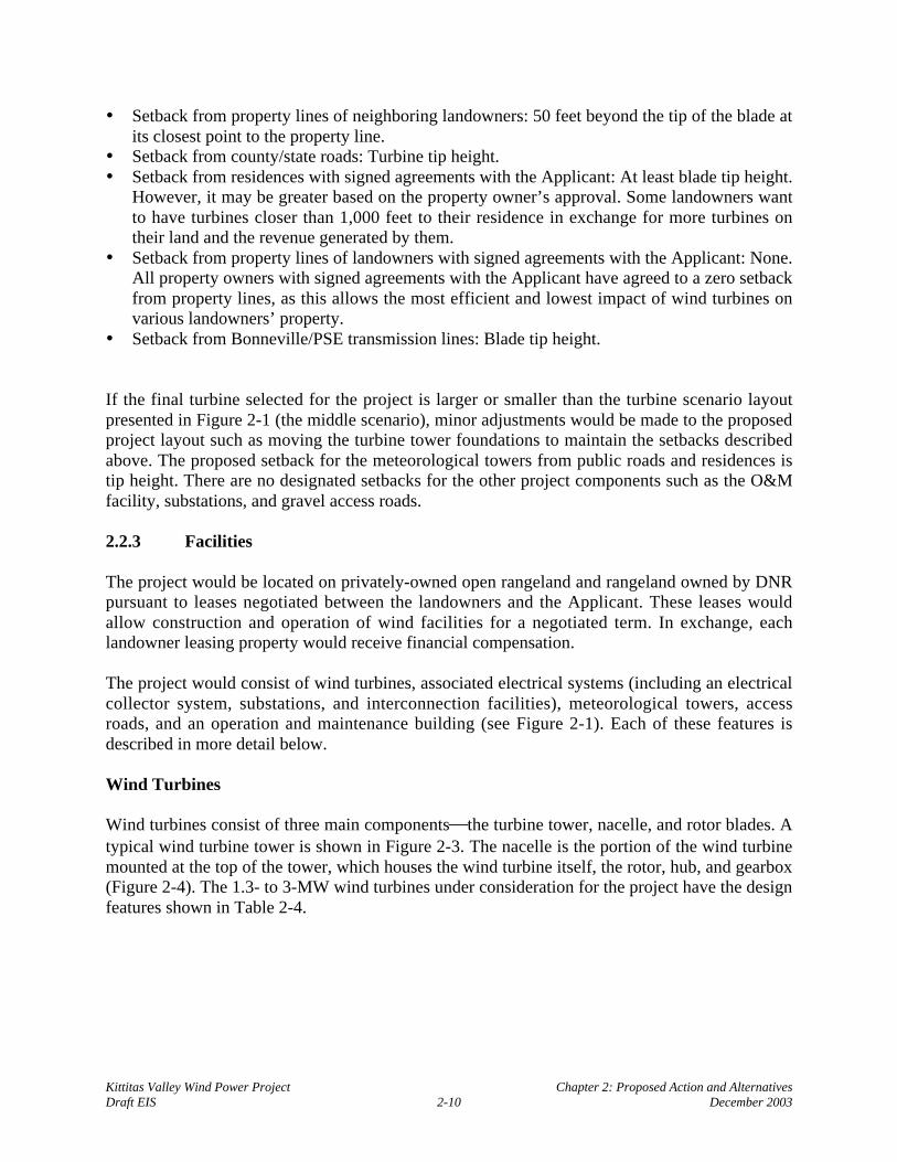
• Setback from property lines of neighboring landowners: 50 feet beyond the tip of the blade atits closest point to the property line.
• Setback from county/state roads: Turbine tip height.• Setback from residences with signed agreements with the Applicant: At least blade tip height.
However, it may be greater based on the property owner’s approval. Some landowners wantto have turbines closer than 1,000 feet to their residence in exchange for more turbines ontheir land and the revenue generated by them.
• Setback from property lines of landowners with signed agreements with the Applicant: None.All property owners with signed agreements with the Applicant have agreed to a zero setbackfrom property lines, as this allows the most efficient and lowest impact of wind turbines onvarious landowners’ property.
• Setback from Bonneville/PSE transmission lines: Blade tip height.
If the final turbine selected for the project is larger or smaller than the turbine scenario layoutpresented in Figure 2-1 (the middle scenario), minor adjustments would be made to the proposedproject layout such as moving the turbine tower foundations to maintain the setbacks describedabove. The proposed setback for the meteorological towers from public roads and residences istip height. There are no designated setbacks for the other project components such as the O&Mfacility, substations, and gravel access roads.
2.2.3 Facilities
The project would be located on privately-owned open rangeland and rangeland owned by DNRpursuant to leases negotiated between the landowners and the Applicant. These leases wouldallow construction and operation of wind facilities for a negotiated term. In exchange, eachlandowner leasing property would receive financial compensation.
The project would consist of wind turbines, associated electrical systems (including an electricalcollector system, substations, and interconnection facilities), meteorological towers, accessroads, and an operation and maintenance building (see Figure 2-1). Each of these features isdescribed in more detail below.
Wind Turbines
Wind turbines consist of three main componentsthe turbine tower, nacelle, and rotor blades. Atypical wind turbine tower is shown in Figure 2-3. The nacelle is the portion of the wind turbinemounted at the top of the tower, which houses the wind turbine itself, the rotor, hub, and gearbox(Figure 2-4). The 1.3- to 3-MW wind turbines under consideration for the project have the designfeatures shown in Table 2-4.

Kittitas Valley Wind Power Project Chapter 2: Proposed Action and AlternativesDraft EIS 2-11 December 2003
Table 2-4: Wind Turbine Features, Kittitas Valley Wind Power Project
DescriptionDesign Feature
Upper End Scenario Middle Scenario Lower End ScenarioRated output of turbine 1.3 MW 1.5 MW 3 MWNumber of turbines 150 121 82Axis Horizontal Horizontal HorizontalRotor orientation Upwind Upwind UpwindMinimum wind speed for turbines to beginoperating
7-10 miles per hour1 7-10 miles per hour1 7-10 miles per hour1
Number of blades Three Three ThreeRotor (blade) diameter 197 feet 231 feet 295 feetTower type Tubular steel Tubular steel Tubular steelTower hub (nacelle) height 150 feet 215 feet 262 feetTotal (tip) height (to top of vertical rotor) 260 feet 330 feet 410 feetRotational speed 10-23 rotations per
minute10-23 rotations perminute
10-23 rotations perminute
Nacelle Fully enclosed steelor steel orreinforcedfiberglass
Fully enclosed steelor steel reinforcedfiberglass
Fully enclosed steelor steel reinforcedfiberglass
Color Neutral gray Neutral gray Neutral graySource: Sagebrush Power Partners LLC 2003a1 Wind turbines rotate in winds as low as 2-3 mph, but generator cut in occurs at 7-10 mph.
Towers
Towers would be approximately 150 to 260 feet tall at the turbine hub (referred to as the “hubheight”) under the upper and lower end scenarios, respectively. With the nacelle and bladesmounted, the total height of the wind turbine (“tip height”) would be approximately 260 to 410feet high with a blade in the vertical position. The towers would be a tubular conical steelstructure manufactured in multiple sections depending on the tower height and approximately 12to 16 feet in diameter at the base. The towers would be painted a neutral gray color to be visuallyless obtrusive. A service platform at the top of each section would allow for access to the tower’sconnecting bolts for routine inspection. A ladder inside the structure would ascend to the nacelleto provide access for turbine maintenance. The tower would be equipped with interior lightingand a safety glide cable alongside the ladder.
The towers would be fabricated and erected in two to three sections. Turbine tower sectionswould be transported to the site on trailers that could each carry one tower section per truck.Tower sections would be delivered by truck to a staging area and then to each tower location.They would be erected using a large construction crane.

Kittitas Valley Wind Power Project Chapter 2: Proposed Action and AlternativesDraft EIS 2-12 December 2003
Figure 2-3:

Kittitas Valley Wind Power Project Chapter 2: Proposed Action and AlternativesDraft EIS 2-13 December 2003
Figure 2-4:

Kittitas Valley Wind Power Project Chapter 2: Proposed Action and AlternativesDraft EIS 2-14 December 2003
Nacelle
The nacelle houses the main mechanical components of the wind turbine generatorthe drivetrain, gearbox, and generator. The nacelle would be equipped with an anemometer and a windvane that signals wind speed and direction information to an electronic controller. A mechanismwould use electric motors to rotate (yaw) the nacelle and rotor to keep the turbine pointed intothe wind to maximize energy capture. An enclosed steel-reinforced fiberglass shell houses thenacelle to protect internal machinery from the elements.
Rotor Blades
Modern wind turbines have three-bladed rotors. The diameter of the circle swept by the bladeswould range from approximately 200 to 300 feet under the upper and lower end scenarios,respectively (that is, each blade would be approximately 100 to 150 feet long). The blades wouldturn at about 10 to 23 rotations per minute (RPM). Generally, larger wind turbine generatorshave slower rotating blades, but the specific RPM values depend on aerodynamic design andvary across machines. The rotor blades would be typically made from glass-reinforced polyestercomposite.
Electrical System
The project’s electrical system would have two key elements: (1) a collector system, whichwould collect energy at between 575 and 690 volts (V) from each wind turbine (depending onthe type of turbine used), increase it to 34.5 kilovolts (kV) through a pad-mounted transformer,and connect to the project substations; and (2) the substations and interconnection facilities,which would transform energy from the collection lines (at 34.5 kV) to the transmission level(230 kV for the PSE line and Bonneville’s Columbia to Covington line or 287 kV forBonneville’s Grand Coulee to Olympia line). A schematic of the electrical collection system andinterconnection facilities is shown in Figure 2-5.
Collector System
Power from the wind turbines would be generated at 575 V to 690 V depending on the type ofwind turbine used for the project. A set of heavy gauge, armored, flexible drop cables wouldconnect to the generator terminals in the nacelle and would pass from the nacelle into the towerwhere they would drop down to a cable support saddle located about 20 to 30 feet below the toptower platform. From the support saddle, the cables would be directed along the side of thetower, along the internal ladder in cable trays, or they would be hung straight down to the basebus cabinet and breaker panel inside the base of the tower. The drop cables would terminateinside the bus cabinet. Another set of cables would run from the bus cabinet through conduits inthe foundation to the pad transformer, ranging in size from 50 to 120 square feet in area; the padtransformer would step up the voltage to 34.5 kV. Some wind turbine generators, such as theVestas V-80, have the transformer in the nacelle. For the V-80, the drop cables would be at 34.5kV, and the base bus cabinet would be a switchgear breaker panel. No outdoor pad transformerwould be required (Sagebrush Power Partners LLC 2003c, Section 2.3.4).

Kittitas Valley Wind Power Project Chapter 2: Proposed Action and AlternativesDraft EIS 2-15 December 2003
From the transformer, power from the turbine would be transmitted by underground 34.5-kVelectrical cables installed in a trench typically 3 to 4 feet deep, depending on the underlying soiland rock conditions, and up to 5 feet wide. Underground collection cables would be used in mostareas; overhead collectors on wood structures would be used where there are steep slopes orcanyons to cross (see Figure 2-1). Approximately 23 miles of underground and 2 miles ofoverhead 34.5-kV electrical power lines would be used to collect power from the turbines andterminate at the main substation.
An estimated 1.2-mile section of the overhead system would be along Bettas Road parallel totwo existing sets of overhead transmission lines and the access road that serves them. Anotheroverhead section is proposed to link turbine strings B and C. In the original site layout (Figure 2-1), this connection was shown as either underground or overhead. Based on subsequent inputfrom the Washington Department of Fish and Wildlife, the Applicant proposes to build this aspart of the overhead system to minimize impacts on the riparian habitat between the tworidgetops. For these short overhead portions of the electrical collection system, wooden poles,non-reflective conductors, and non-refractive insulators would be used (Sagebrush PowerPartners LLC 2003d). Overhead poles typically would be approximately 60 feet tall andpositioned so that poles and electrical conductors are spaced at least 200 feet apart. The poleswould be buried 8 to 10 feet deep. Pole insulators would be spaced four feet apart. Anti-perchingdevices would be installed on the poles to limit potential raptor use.
The electrical collection system would include junction boxes and pad-mounted switchgearpanels that would be installed to connect cables coming from different directions and to allow forthe isolation of particular turbine strings. In total, it is estimated that 15 junction boxes and 10switch panels would be required for the electrical collection system (Sagebrush Power PartnersLLC 2003c, Section 2.3.4).
Junction Boxes
The junction boxes would be either steel-clad or fiberglass panels mounted on pad foundationsroughly 4 feet wide, 6 feet long, and 6 feet high. The pad foundation would have an undergroundvault about 3 feet deep where the underground cables come in. The junction boxes also wouldhave a buried grounding ring with grounding rods tied to the collection system and a commonneutral.
Switch Panels
The switch panels would be steel-clad enclosures mounted on pad foundations roughly 7 feetwide, 7 feet long, and 5 feet high. Switches would allow particular collector lines and turbinesstrings to be turned off or isolated. This isolation would allow maintenance and repair to takeplace without shutting down the entire project. The pad foundation would have an undergroundvault about 3 feet deep where the underground cables come in. Switch panels also would have aburied grounding ring with grounding rods tied to the collection system and a common neutral .

Kittitas Valley Wind Power Project Chapter 2: Proposed Action and AlternativesDraft EIS 2-16 December 2003
Figure 2-5:

Kittitas Valley Wind Power Project Chapter 2: Proposed Action and AlternativesDraft EIS 2-17 December 2003
Substations and Interconnection Facilities
The Applicant is seeking a permit for and is designing the project so that it could interconnectwith either the PSE or Bonneville electrical transmission lines traversing the site or possiblyboth. If connected to Bonneville’s system, the project would interconnect directly with either theGrand Coulee to Olympia 287-kV line or the Columbia to Covington 230-kV line. If connectedto PSE’s system, the project would interconnect directly with PSE’s Rocky Reach to WhiteRiver 230-kV line. There is the possibility that power would be fed to both the PSE andBonneville systems; therefore, this analysis evaluates the need to construct two substations sincethe lines have different voltages.
The Applicant would build and maintain up to two fenced substation sites, each occupyingapproximately 3 acres. The proposed PSE substation would be in the northwest corner of theintersection of US 97 and Bettas Road, and the Bonneville substation would be approximately2,200 feet southwest of the PSE substation, south of Bettas Road near the Bonnevilletransmission lines. The main function of the substations and interconnection facilities would beto step up the voltage from the collection lines (at 34.5 kV) to the transmission level (230 or 287kV) to interconnect to the appropriate utility grid. The basic elements of the substation andinterconnection facilities are a control house, two main transformers, outdoor breakers, relayingequipment, steel support structures, and overhead lightning suppression conductors. All of theelements would be installed on concrete foundations designed for site-specific soil conditions.
Meteorological Towers
Meteorological towers are used to measure wind conditions, including wind speed, direction, andtemperature. The Applicant proposes to erect up to nine permanent meteorological towers in theproject area, although it is likely that only four would be constructed. The potential location ofthe nine proposed permanent meteorological towers is shown in Figure 2-1. The permanentmeteorological towers installed for the project would be approximately as tall as the turbinetower hub height (i.e., 150 to 262 feet) and would consist of a central lattice structure supportedby three to four sets of guy wires that extend up to 100 to 210 feet from the base of each tower,on a 16-foot-by-16-foot base. The towers may alternatively be of a free standing design. Themeteorological towers would be constructed upwind of turbine strings or groups of turbinestrings to monitor wind strength and to confirm turbine performance. Meteorological towersgreater than 200 feet in height would require lighting in compliance with the Federal AviationAdministrations’ (FAA) aircraft safety lighting requirements (see the lighting discussion belowfor further detail).
Meteorological towers would be installed with a grounding system that protects themeteorological sensors and loggers from electrostatic discharge and lightning. Lightningdissipaters or rods would be installed at the tops of the towers to provide an umbrella ofprotection for the upper sensors (Sagebrush Power Partners LLC 2003c, Section 2.3.8).

Kittitas Valley Wind Power Project Chapter 2: Proposed Action and AlternativesDraft EIS 2-18 December 2003
Access Roads
Access to the various rows of turbines would be achieved by graveled access roads branchingfrom US 97 and two county roadsBettas and Hayward roads. The project would improve someexisting private roads and construct new gravel roads to provide access for construction vehiclesand equipment. Up to approximately 7 miles of existing private roads would need to be improvedand up to 19 miles of new roads would be constructed. The roads would be 24 feet wideincluding shoulders for small wind turbine generators (i.e., under the middle and upper endscenarios) and 34 feet wide including shoulders for larger wind turbine generators (i.e., under thelower end scenario) with a compacted gravel surface. In areas of steeper grades, a cut and filldesign would be implemented to keep grades below 15% and to prevent erosion. After theproject is constructed, use of the improved and new access roads on private lands would belimited to the landowner and to project maintenance staff.
Operation and Maintenance Facility
A permanent O&M facility would be constructed near the northwest corner of US 97 and BettasRoad. It would consist of approximately 5,000 square feet of enclosed space, including offices,spare parts storage, kitchen, restrooms, and a shop area. Water for the bathroom and kitchenwould be obtained from a new domestic well; anticipated water use would be less than 1,000gallons a day. Wastewater from the facility would be discharged to an onsite domestic septictank. There also would be graveled outdoor parking, a turnaround area for larger vehicles,outdoor lighting, and gated access with either partial or full perimeter fencing. The overall areaof the building and parking would be approximately 2 acres. Vehicle access to the O&M facilitywould occur from Bettas Road.
Information Kiosk
An information kiosk and public viewing area near the proposed O&M facility off Bettas Roadwould be constructed. Signs would be provided to direct tourists to this site (Sagebrush PowerPartners LLC 2003c, Section 5.3). Vehicle access to the information kiosk and public viewingarea would occur from Bettas Road at the same location as the access to the O&M facility.
Safety Features and Control Systems
Turbine Control Systems
Wind turbines would be equipped with sophisticated computer control systems that wouldconstantly monitor variables such as wind speed and direction, air and machine temperatures,electrical voltages, currents, vibrations, blade pitch, and yaw angles. The main function of thecontrol system would be nacelle and power operations. Generally, nacelle functions includeyawing the nacelle into the wind, pitching the blades, and applying the brakes if necessary.Power operations controlled at the bus cabinet inside the base of the tower include operation ofthe main breakers to engage the generator with the grid as well as control of ancillary breakersand systems. The control system would always run to ensure that the machines operateefficiently and safely.

Kittitas Valley Wind Power Project Chapter 2: Proposed Action and AlternativesDraft EIS 2-19 December 2003
Each turbine would be connected to a central Supervisory Control and Data Acquisition(SCADA) system. The SCADA system would allow for remotely controlling and monitoringindividual turbines and the wind plant as a whole from both the central host computer or from aremote personal computer. In the event of faults, the SCADA system can also send signals to afax, pager, or cell phone to alert operations staff. The turbine towers and foundations would bedesigned to survive a gust of wind more than 90 miles per hour (mph) with the blades pitched intheir most vulnerable position, a speed which exceeds the 100-year expected peak gust of 73mph in the project area and the recent maximum recorded gust of 56 mph.
Braking Systems
The turbines would be equipped with two fully independent braking systems that can stop therotor either acting together or independently. The braking system is designed to be fail-safe,allowing the rotor to be brought to a halt under all foreseeable conditions. The system wouldconsist of aerodynamic braking by the rotor blades and by a separate hydraulic disc brakesystem. Both braking systems would operate independently such that if there is a fault with one,the other can still bring the turbine to a halt. Brake pads on the disc brake system would bespring loaded against the disc, and power would be required to keep the pads away from the disc.If power is lost, the brakes would be mechanically activated immediately. The aerodynamicbraking system also would be configured such that if power is lost it would be activatedimmediately using back-up battery power or the nitrogen accumulators on the hydraulic system,depending on the turbine’s design.
After an emergency stop is executed, remote restarting is not possible. The turbine must beinspected in-person and the stop-fault must be reset manually before operation could bereactivated. The turbines also would be equipped with a parking brake used to keep the rotorstationary while maintenance or inspection is performed.
Built-in Fire Safety
Each turbine’s nacelle would be equipped with an internal fire detection system with sensorslocated in the nacelle as well as at the tower base. The fire detection system would be connectedto the main controller and the central SCADA system. In the event of a fire, the turbine would beimmediately halted and an alarm activated in the control system that can send a page or messageto a cell phone of the on-call operators and/or the local fire district as required.
Climbing Safety
Normal access to the nacelle would be accomplished with a ladder inside the tower. Standardtower hardware would include equipment for safe ladder climbing including lanyards and safetybelts for service personnel. Internal ladders and maintenance areas inside the tower and nacellewould be equipped with safety provisions for securing lifelines and safety belts.

Kittitas Valley Wind Power Project Chapter 2: Proposed Action and AlternativesDraft EIS 2-20 December 2003
Lightning Protection
The turbines would be equipped with an engineered lightning protection system that connects theblades, nacelle, and tower to a grounding system at the base of the tower. The grounding systemwould include a copper ring conductor connected to grounding rods driven down into the groundat diametrically opposed points outside the tower foundation. The system would provide a firmgrounding path to divert harmful stray surge voltages away from the turbine. The blades wouldbe constructed with an internal copper conductor and an additional lightning rod that extendsabove the wind vane and anemometer at the rear of the nacelle; both would have conductivepaths to the nacelle bed frame, which in turn would connect to the tower.
Lighting
In compliance with the FAA’s aircraft safety lighting requirements, project turbines, as well asmeteorological towers greater than 200 feet tall, would be marked with lights that flash whiteduring the day (at 20,000 candela) and red at night (at 2,000 candela). (A candela is a unit ofluminous intensity.) The lights would be designed to concentrate the beam in the horizontalplane, minimizing light diffusion downward toward the ground and upward toward the sky. Afterit has reviewed final project plans, the FAA would specify the exact number of turbines thatwould require lighting. Under current (June 2003) FAA regulations, the navigation lights wouldneed to be mounted on the first and last turbine of each string and every 1,000 to 1,400 feet inbetween.
The substations and O&M facility would be equipped with nighttime and motion-sensor lightsfor safety and security. Sensors and switches would be used to keep lights turned off when notrequired. Emergency lighting with back-up power is included to allow personnel to performmanual operations during an outage of normal power sources.
2.2.4 Construction Activities
Project construction would be performed in several stages and would include the following mainactivities:
• Grading the field construction office and substation areas (also used for the O&M facility);• Constructing site roads, turnaround areas, and crane pads at each wind turbine location;• Constructing turbine tower foundations and transformer pads;• Installing the electrical collection systemunderground and overhead lines;• Constructing and installing the substations;• Transporting and assembling wind turbines;• Commissioning and energizing the plant; and• Cleaning up the site.
The Applicant intends to enter into two primary agreements for project construction including anagreement for the supply, erection, and commissioning of the wind turbines as well as anengineering, procurement, and construction (EPC) contract for all other project facilities andinfrastructure such as the roads, electrical collection system, substations, and O&M facility.

Kittitas Valley Wind Power Project Chapter 2: Proposed Action and AlternativesDraft EIS 2-21 December 2003
Table 2-5 lists the estimated type, number, and duration of construction equipment neededduring project construction under the middle scenario. Project construction would requireapproximately the same type, number, and duration of equipment regardless of whether 82 unitsof large size turbines (lower end scenario) or 150 units of small wind turbines (upper endscenario) are built (Sagebrush Power Partners LLC 2003f).
Table 2-5: Estimated Type, Number, and Duration of Project Construction Equipment
Construction PhaseEstimated Average Number of Vehicles
Onsite Daily during ConstructionEstimated Duration
(Months)
Site Preparation and Road ConstructionBulldozer 4 3Dump truck 10 3Excavator 4 3Front end loader 4 3Motor grader 4 3Vibratory roller 3 3Water truck 5 8FoundationsBackhoe 4 4Crane and boom truck 3 4Concrete pump truck 2 4Concrete truck 8 4Drill rig 3 4Dump truck 6 4Trackhoe excavator 5 4Front end loader 3 4Small loader 3 4Transportation truck – materials 6 4ElectricalCable spool truck 3 4Concrete truck 3 4Boom truck 2 4Fork truck to offload spools 2 4Man lift bucket 2 4Rock trencher 2 4Transportation truck - materials 8 4Winch truck 3 4Substation and InterconnectBackhoe 3 3Bulldozer 2 3Concrete truck 4 3Drill rig 2 3Dump truck 4 3Man lift bucket truck 2 3Trencher 2 3Winch truck 1 3Excavator 2 3Wind Turbine Assembly and ErectionBoom truck 4 4Forklift 4 4Rough terrain crane 4 4

Kittitas Valley Wind Power Project Chapter 2: Proposed Action and AlternativesDraft EIS 2-22 December 2003
Table 2-5: Continued
Construction PhaseEstimated Average Number of Vehicles
Onsite Daily during ConstructionEstimated Duration
(Months)
Transportation truck - materials 20 4Truck mounted crane 4 4Project CleanupDump truck 2 2Front end loader 2 2Motor grader 2 2Transportation truck - materials/waste 3 2Daily Construction TrafficMinimum of 20 full size pickups, FedEx,
UPS, and other delivery trucks daily35 10
Source: Sagebrush Power Partners LLC 2003c
Field Survey and Geotechnical Investigations
Before construction can commence, a site survey would be performed to identify the preciselocation of the wind turbines, site roads, electrical cables, access entryways from public roads,and substation areas. Once the surveys are complete, a detailed geotechnical investigation wouldbe undertaken to identify subsurface conditions that would dictate much of the design work ofthe roads, foundations, underground trenching, and electrical grounding systems. Typically, thegeotechnical investigation involves a drill rig that bores to the required depths (typically 8-inch-diameter drill, 30 to 40 feet deep) and a backhoe to identify the subsurface soil and rock typesand strength properties by sampling and lab testing. Testing also would be conducted to measurethe soil’s electrical properties to ensure proper grounding system design. A geotechnicalinvestigation would be performed at each turbine location, at the substations, and at the O&Mfacility.
Design and Construction Specifications
Using data gathered for the project including geotechnical information, site specificenvironmental and climatic conditions, and site topography, the Applicant’s engineering groupwould establish a set of site-specific construction specifications for various portions of theproject. The design specifications would be based on established sets of construction standardsset forth by standard industry practice groups such as the American Concrete Institute, Institutefor Electrical and Electronic Engineers, National Electric Code, National Fire Protection Agency,and Construction Standards Institute. The design and construction specifications would becustom tailored for site-specific conditions by technical staff and engineers. The projectengineering team also would ensure that all aspects of the specifications, as well as the actualonsite construction, comply with applicable federal, state, and local codes and good industrypractice.
Equipment procurement would be according to the project’s site specifications. The primaryEPC contractor would use the design specifications as a guideline to complete the detailed

Kittitas Valley Wind Power Project Chapter 2: Proposed Action and AlternativesDraft EIS 2-23 December 2003
construction plans for the project. The design approach ensures that the project would bedesigned and constructed to meet the minimum 20-year design life.
Site Preparation: Road Construction and Staging and Laydown Areas
Construction activities would begin with site preparation, including constructing project accessentryways from public roads. The project roads would have a gravel surface and would bedesigned with a low profile without ditches to allow stormwater to pass over the top. Roadconstruction would be performed in multiple phases starting with rough grading and levelingroadway areas. Once rough grade is achieved, base rock would be trucked in, spread, andcompacted to create a road base. A capping rock would then be spread over the road base andcompacted to the finished grade.
Once heavy construction is complete, a final pass would be made with the grading equipment tolevel out road surfaces, and more capping rock would be spread and compacted in areas whereneeded. Water bars, similar to speed bumps, would be cut into the roads in certain areas asneeded to allow for natural drainage of water over the road surface and to prevent road washout.During grading activities, excavated soil and rock would be spread across the site to the naturalgrade and would be reseeded with native grasses to control erosion by water and wind. Largerexcavated rocks would be disposed of offsite or crushed and reused onsite as backfill or roadwaymaterial. The Applicant does not propose to bring a rock crusher onsite, but would transport thismaterial to the existing permitted quarry located just north of turbine F1 for crushing prior toreuse (Taylor, pers. comm., 2003).
During wind turbine installation, temporary staging and laydown areas would be required. Theseareas would include a 3-acre main staging area and a 5-acre material laydown area at the O&Mfacility location adjacent to the proposed PSE substation (Figure 2-1). These areas would be usedfor parking construction vehicles, construction employees’ personal vehicles, and otherconstruction equipment. Six to eight temporary office trailers powered by the existing localdistribution line running along Bettas Road also would be installed at this location.
Under the middle and upper end scenarios, flat areas adjacent to each turbine location,approximately 30 feet by 60 feet (1,800 square feet), would be cleared, compacted, and laid withgravel as necessary to place turbine blades and other turbine components and to station aconstruction crane as each tower is erected. Wind turbine generators larger than 1.5 MW (e.g.,under the lower end scenario) would require installation by a crawler crane operating on a cranepad approximately 50 feet by 100 feet (5,000 square feet). At the end of most turbine strings(except where a turbine string is adjacent to a through-traffic road), an area approximately 900feet by 24 feet (21,600 square feet or 0.5 acres) also would be needed to allow constructionequipment to turn around. After construction has been completed, laydown and staging areaswould be graded and reseeded to restore the area as close as possible to its original condition.
Foundation Construction
The project would require several foundations including bases for each turbine and padtransformer, substation equipment, and the O&M facility. Once the roads are complete for a

Kittitas Valley Wind Power Project Chapter 2: Proposed Action and AlternativesDraft EIS 2-24 December 2003
particular row of turbines, turbine foundation construction would commence on that completedroad section. Foundation construction occurs in several stages including drilling, blasting, andhole excavation, outer form setting, rebar and bolt cage assembly, casting and finishing concrete,removing the forms, backfilling and compacting, constructing the pad transformer foundation,and foundation site restoration.
Foundations for the turbine towers would consist of either spread footing-type foundation designor a vertical mono-pier foundation. The specific type of foundation would be determined basedon site-specific geotechnical information to be collected after project approval. The foundationdesign would be tailored to suit the soil and subsurface conditions at the various turbine sites.Typical dimensions for spread footing-type foundation design under the lower, middle, andupper end scenarios are shown in Table 2-6.
Under the middle scenario, spread footing foundations would require holes approximately 100feet by 100 feet square and about 18 feet deep. Backfill would be compacted in the bottom of thehole and reinforced square concrete footing would be poured. A reinforced concrete pedestalapproximately 10 feet high would be mounted on the concrete footing to hold the tower. Theconcrete footing would be covered with approximately 6 to 8 feet of compacted backfill and 4 to6 inches of topsoil depending on soil conditions.
Table 2-6: Typical Spread-Footing Type Foundation Dimensions
Lower End Scenario82 Turbines/3 MW
Middle Scenario121 Turbines/1.5 MW
Upper End Scenario150 Turbines/1.3 MW
Foundation Base Line 80’ x 80’ 60’ x 60’ 50’ x 50’Pad Depth 10’ 8’ 6’Pedestal Height 12’ 10’ 8’Overall Depth 22’ 18’ 14’Hole Dimensions 120’ x 120’ 100’ x 100’ 80’ x 80’Hole Depth 22’ 18’ 14’Source: Sagebrush Power Partners LLC 2003f.
Vertical mono-pier foundations would require excavating a hole up to 35 feet deep and up toapproximately 18 feet in diameter. If the underlying rock is cohesive, competent and strongenough, rock anchors can be used which will allow the excavation to be as shallow as 15 feetdeep.
The construction process for the foundations would vary depending on the foundation engineer’srequirements and soil conditions found at the site. The construction process may have variancesfrom site to site if soil conditions are different from location to location; however it generallyfollows the same main steps regardless of which turbine configuration is used for the project asfollows:

Kittitas Valley Wind Power Project Chapter 2: Proposed Action and AlternativesDraft EIS 2-25 December 2003
Mono-Pier Type Foundation
• Clearing and grubbing the area with a bulldozer at the exact surveyed turbine location• Initial excavation of the foundation hole with a track hoe• Drilling and setting of charges and blasting out excavation center and perimeter
simultaneously• Loosen rock with hydraulic jack hammer• Excavation of foundation hole with the track hoe• Installation and setting of the outer corrugated metal pipe (CMP) form and backfill or slurry
into place• Construct the bolt cage inside the CMP• Insert inner CMP• Backfill the inner CMP with remaining suitable spoils• Set outer forms for tower floor and electrical conduits• Pour Concrete into place for foundation• Remove Forms• Dispose of remaining spoils• Restore temporarily disturbed surfaces
Spread Footing Type Foundation
• Clearing and grubbing the area with a bulldozer at the exact surveyed turbine location• Initial excavation of the foundation hole with a track hoe• Drilling and setting of charges and blasting out excavation area center and perimeter• Loosen rock with hydraulic jack hammer• Full excavation of foundation hole with the track hoe• Installation and setting of the outer forms and pour concrete base mat (3-4 inches thick)• Construct reinforcement bar (rebar) mat and pedestal anchor bolt cage• Assemble forms in place for pedestal, Pour concrete, allow to set and remove forms• Backfill the excavation• Set outer forms for tower floor pad and electrical conduits and pour Concrete into place for
floor• Dispose of remaining spoils• Restore temporarily disturbed surfaces
Excavation and foundation construction would be conducted in a manner that would minimizethe size and duration of excavated areas required to install foundations. Portions of the work mayrequire overexcavation and/or shoring. Foundation work for a given site would commence afterexcavation of the area is complete. Backfill for the foundations would be installed immediatelyafter approval by the engineer’s field inspectors. The Applicant plans to use onsite excavatedmaterials for backfill to the extent possible. The excess excavated materials not used as backfillfor the foundations would be used to level out low spots on the crane pads and roads consistentwith the surrounding grade. The top soil layer of the excavated materials would be reseeded witha designated mix of grasses and/or seeds around the edges of the disturbed areas. Larger cobbleswould be disposed of offsite or crushed into smaller rock at the nearby existing permitted quarryfor use as backfill or road material.

Kittitas Valley Wind Power Project Chapter 2: Proposed Action and AlternativesDraft EIS 2-26 December 2003
Electrical Collection System Construction
Underground Cables
Once the roads, turbine foundations, and transformer pads are complete for a particular row ofturbines, underground cables would be installed on that completed road section. First, a trenchwould be cut with a rock trencher typically 3 to 4 feet deep depending on the underlying soil androck conditions and up to 5 feet wide. Because of the rocky conditions at the site, clean fillwould be placed above and below the cables for the first several inches of fill to prevent cablepinching. All cables and trenches would be inspected before backfilling. Once the clean fillcovers the cables, the excavated material would be used to complete the backfilling. In areaswhere solid rock is encountered close to the surface, blasting would be performed or a shallowertrench would be cut using rock-cutting equipment, and the cables would be covered with aconcrete slurry mix to protect the cables and comply with code and engineering specifications.
The high voltage underground cables would be fed through trenches and into conduits at the padtransformers at each turbine. The cables would run to the pad transformers’ high voltage (34.5kV) compartment and would be connected to the terminals. Low voltage cables would be fedthrough another set of underground conduits from the pad transformer to the bus cabinet insidethe base of the wind turbine tower. The low voltage cable would be terminated at each end andthe whole system would be inspected and tested prior to operation.
Overhead Cables
The two runs of overhead cable would require a detailed field survey to determine exact polelocations. Once the survey and design work are completed, the poles and cross-arms to supportthe conductors would be installed. The poles would be assembled and fitted with cross-arms,cable supports, and insulator hardware on the ground at each pole location. Holes, approximately150 square feet (8 feet by 8 feet to 12 feet by 12 feet) in size and 8 feet to 10 feet deep for eachpole, would be excavated or drilled and the poles would be erected and set in place using a smallcrane or boom truck. Once set in place, concrete would be poured in place or a clean fill wouldbe compacted around the tower base according to the engineer’s specifications.
Excavated soil and rock not reused in backfilling the trenches would be spread across the site tothe natural grade and be reseeded with native grasses to control water and wind erosion. Largerexcess excavated rocks would be disposed of offsite.
Substation and Interconnection Facility Construction
Constructing the substations and interconnection facilities would involve several stages of workincluding, but not limited to, grading; constructing foundations for the transformers, steel work,breakers, control houses, and other outdoor equipment; erecting the steel work and outdoorequipment; and completing electrical work for the required terminations. Once these activitiesare completed, an inspection and commissioning test plan would be executed prior to substationoperation.

Kittitas Valley Wind Power Project Chapter 2: Proposed Action and AlternativesDraft EIS 2-27 December 2003
The utility (PSE or Bonneville) would be responsible for constructing the interconnectionfacilities because they would remain under the utility’s control and jurisdiction. The high-voltageside of the substation would remain under the control of the utility and the low-voltage side ofthe substation would belong to the project. A fence may be installed between the high and lowvoltage sections to delineate control and jurisdiction, and there would likely be two controlhousesone for the utility high-voltage side relaying and interconnection facilities controls andone for the project substation low-voltage side relaying and controls.
Transporting Tower Sections and Assembling Towers
The wind turbines would have three main componentstowers, nacelles, and rotor blades. Othersmaller components include hubs, nose cones, cabling, control panels, and internal towerfacilities such as lighting and ladders. Turbine components would be delivered to the project siteon flatbed transport trucks and main components would be off-loaded at the individual turbinesites. Turbine erection would be performed in multiple stages including: setting the bus cabinetand ground control panels on the foundation, erecting the tower (usually in three to foursections), erecting the nacelle, assembling and erecting the rotor, connecting and terminating theinternal cables, and inspecting and testing the electrical system prior to operation.
Plant Commissioning and Energizing
Plant commissioning and energizing would occur after construction is completed and would notrequire the use of heavy machinery.
Erosion Control, Site Cleanup and Temporary Site Disturbance Restoration
A detailed construction Storm Water Pollution Prevention Plan (SWPPP) would be developedfor the project to help minimize the potential for discharge of pollutants from the site duringconstruction. The SWPPP would be designed to meet the requirements of the Washington StateDepartment of Ecology’s General Permit to Discharge Storm Water through its stormwaterpollution control program (Chapter 173-220 WAC) associated with construction activities. TheSWPPP would include both structural and non-structural BMPs. Examples of structural BMPscould include installing silt curtains or other physical controls to divert flows from exposed soils,or otherwise limit runoff and pollutants from exposed areas of the site. Examples of non-structural BMPs include management practices such as materials handling and disposalrequirements and spill prevention methods. The Applicant would prepare and submit a SWPPPmeeting the conditions of the General Permit to Discharge Storm Water to EFSEC along with aNotice of Intent (NOI) for construction activities prior to the start of project construction.
After construction is completed, site restoration activities would consist of restoring temporarilydisturbed areas as close as possible to their original condition. This excludes the service roads,which would remain in place for the life of the project. For example, after backfilling excavatedareas disturbed to construct underground electrical cables, excess excavated soils would bespread around the surrounding areas and contoured to the natural grade. The areas affected byconstruction would then be seeded with an appropriate seed mix where there is adequate soilmoisture, as appropriate to the location, and would be re-seeded if healthy cover vegetation does

Kittitas Valley Wind Power Project Chapter 2: Proposed Action and AlternativesDraft EIS 2-28 December 2003
not grow. Similar restoration activities would be followed at areas temporarily disturbed forconstruction staging, equipment laydown, and temporary construction access. Onsiteconstruction management would monitor the area for erosion and implement additional controlmeasures if necessary.
Since project cleanup generally consists of landscaping and earthwork, it is weather- and season-sensitive. Landscaping cleanup is generally completed during the first allowable and suitableweather conditions after heavy construction activities have been completed. As described above,disturbed areas outside of the graveled areas would be reseeded to control erosion by water andwind. Construction cleanup and permanent erosion-control measures would be carried out inaccordance with the project SWPPP. Other project cleanup activities might include interiorfinishing of the O&M facility, landscaping around the substation area, washing towers, paintingscratches on towers and exposed bolts, and other miscellaneous tasks that are part of normalconstruction cleanup.
Construction Site Security
A full-time security plan would be implemented during project construction. A full-time bondedsecurity officer would be on duty and would patrol the project site 24 hours per day, seven daysper week. The officer would patrol the entire project site but would focus on those portions of thesite that were under active construction. Site staff and subcontractors would be required to wearan identity badge and display vehicle clearance tags at all times. Newcomers to the project sitewould have to check in, log in, and log out at the main site’s construction trailers. Theconstruction trailers would be equipped with outdoor lighting and motion-sensor lighting asrequired.
Construction materials would be stored at the individual turbine locations or at the laydown areaaround the perimeter of the O&M facility and site construction trailers. Temporary fencing witha locked gate would be installed for a roughly 1.5-acre area adjacent to the site trailers for thetemporary storage of special equipment or materials. After construction is completed, thetemporary fencing would be removed and the area reseeded with an appropriate seed mix.
The site project manager would work with a security contractor to develop a plan to effectivelymonitor the overall site during construction including drive-by surveys and specific checkpoints.The security inspection and monitoring plan would be changed throughout the course ofconstruction based on the level of construction activity and amount of sensitive or vulnerableequipment and materials in specific areas.
Construction Schedule and Workforce
The Applicant anticipates that project construction would occur over a period of approximatelyone year from the time of site certification to commercial operation and would require theinvolvement of 253 personnel (Table 2-7). However, not all workers would be onsite at the sametime. A peak workforce of up to 160 workers would be onsite during the busiest constructionmonth when multiple disciplines of contractors complete work simultaneously (Table 2-8). It is

Kittitas Valley Wind Power Project Chapter 2: Proposed Action and AlternativesDraft EIS 2-29 December 2003
estimated that local workers from Kittitas County would fill at least 40 of the projected 253construction jobs.
Project construction would require approximately the same level of manpower and timeregardless of whether 82 units of large size turbines (lower end scenario) or 150 units of smallwind turbines (upper end scenario) are used. The larger turbines require a higher level ofmanpower and time for construction and erection since the foundations and roads are larger andpreparation work for assembly requires more manpower on a per unit basis compared to thesmaller turbines, however there are fewer units to build. Regardless of the project configuration,it would require a total of approximately 253 staff to construct the project (Sagebrush PowerPartners LLC 2003f). Some of the labor trades anticipated to be required during projectconstruction include electricians, riggers, crane operators, blasting specialists, and heavyequipment operators (Taylor, pers. comm., 2003).
Table 2-7: Construction Labor Force Mix (Approximate Number of Personnel)
Construction PhaseProject
Managementand Engineers
FieldTechnical
Staff
Skilled Laborand Equipment
Operators
UnskilledLabor
Total
Engineering/surveying/design 6 12 0 0 18Road construction 5 5 15 5 30Foundation construction 3 4 23 30 60Electrical collection system construction 2 3 23 12 40Substation construction 5 3 8 4 20Wind turbine assembly and erection 4 6 15 15 40Commissioning and energizing the plant 5 10 15 0 30Construction punchlist cleanup 1 1 3 10 15Total 31 44 102 76 253Source: Sagebrush Power Partners LLC 2003a, Section 2.12.3
Table 2-8: Construction Labor Resource Loading (Approximate Number of Personnel)
Number of Months Priorto Commercial Operation
Project Managementand Engineers
Field TechnicalStaff
Skilled Labor andEquipment Operators
UnskilledLabor
Total
14 6 0 0 0 613 6 12 0 0 1812 5 5 15 5 3011 8 9 38 35 9010 10 12 61 47 1309 10 12 61 47 1308 10 10 54 46 1207 10 10 54 46 1206 14 16 69 61 1605 14 19 38 19 904 9 16 30 15 703 9 16 30 15 702 9 16 30 15 701 5 10 15 0 300 5 10 15 0 30
Cleanup 1 1 3 10 15Source: Sagebrush Power Partners LLC 2003a, Section 2.12.3

Kittitas Valley Wind Power Project Chapter 2: Proposed Action and AlternativesDraft EIS 2-30 December 2003
2.2.5 Operation and Maintenance Activities
Routine Operation and Maintenance
The amount of downtime from scheduled maintenance is predictable from year to year. Theproposed project’s operating plan includes a planned outage schedule that consists of windturbine inspections and maintenance after the first three months of operation, a break-indiagnostic inspection (includes inspection of oil and all other elements of the wind turbinegenerator) and subsequent services every six months. The six-month servicing generally takes awind turbine off-line for one day. The six-month routine consists of inspecting and testing safetysystems; inspecting wear and tear on components such as seals, bearings, and bushings;lubricating the mechanical systems; performing electronic diagnostics on the control systems;verifying pre-tension of the mechanical fasteners; and inspecting the overall structuralcomponents of the wind turbines. Blades would be inspected and, if heavily soiled, rinsed onceper year to maintain overall aerodynamic efficiency. Blade washing is not anticipated as arequirement for the project since fall and spring rains would remove most if not all of the dirt.
Electrical equipment such as breakers, relays, and transformers requires weekly visualinspections, which does not affect overall availability, and testing or calibrations every one tothree years, which may force outages. To the extent practical, the short-term off-line routinemaintenance procedures would be coordinated with periods of little or no wind to minimize theimpact on the amount of overall energy generation.
Unscheduled Maintenance - Forced Outages
Historically, modern wind power projects operate with availabilities in the 95 to 99% range.Several components and systems of an individual wind turbine can be responsible for forced,non-routine outages such as the malfunction of mechanical and electrical components, orcomputer controls. It is anticipated that most of the outages would result from auxiliaries andcontrols, not malfunction or failure of the heavy rotating machinery. Most machinery failures arefound during routine inspections, with the failing part being replaced before complete failure.
Although the newer control systems have added a high level of detection and diagnosticcapability, they normally require frequent minor adjustments in the first few months ofoperation. As a result, available energy from wind power projects is generally lower in the firstfew months until the turbines are fully tuned. Once a wind plant is properly tuned, unplannedoutages are rare and downtime is limited to the routine service schedule.
The O&M facility would be stocked with sufficient spare parts to support high levels ofavailability during operation. The modular design of modern wind turbines allows most of theparts to be quickly changed, especially in the electrical and control systems. This modularity andthe fact that the turbines would be identical means components could be swapped betweenturbines to quickly determine causes of failures even if the correct spare part is not in stock. Aspart of their supply agreements, almost all major turbine equipment vendors guarantee theavailability of spare parts for 20 years.

Kittitas Valley Wind Power Project Chapter 2: Proposed Action and AlternativesDraft EIS 2-31 December 2003
General project operations would require between 12 and 20 onsite staff consisting of a plant/sitemanager, operations manager, administration manager, administrative assistant, and operatingtechnicians. The number of onsite personnel is not only determined by the number of turbines,but also the type of turbine selected since some turbines require more man-hours of maintenanceper year than others. Under the upper end scenario, using 150 units of relatively maintenance-intensive wind turbines could require up to 18 to 20 personnel. Under the lower end scenario, 82units of less maintenance intensive turbines would require as few as 12 to 14 onsite staff. Themiddle scenario assumes a conservative estimate of 121 units of relatively low maintenanceturbines for which it was estimated that 12 to 14 onsite staff would be required for operations(Sagebrush Power Partners LLC 2003f). It is estimated that approximately one half of the full-time staff would be hired locally (i.e., from within Kittitas County).
Site Security
The plant operations group would prepare a detailed security plan to protect the project andproject personnel. Site visitors including vendor equipment personnel, maintenance contractors,material suppliers, and all other third parties would require permission for access fromauthorized project staff at the O&M facility prior to entrance to secured project areas such as theturbines and substations. The plant operations manager, or designee, would grant access tocritical areas of the site on an as-needed basis. Arrangements would be made with adjacentlandowners that have legal ingress and egress easements across areas where project facilitieswould be located to ensure continued access to their property.
Currently, almost all existing field access driveways in the area are equipped with lockable gates.Similarly, access to the main O&M facility area, site trailers, and all wind turbine string roadswould be constructed with lockable gates. The access gates would be open during working hoursand would be secured by project security personnel after working hours.
Both the O&M facility and the substations would be equipped with outdoor lighting and motion-sensor lighting. The PSE substation would be visible from the O&M facility. An 8-foot-tallchain-link fence would surround the substations with razor wire along the top. Wind turbines,pad transformers, pad-mounted switch panels, and other outdoor facilities would have secure,lockable doors.
An Emergency Response Plan would be established for the project to ensure employee safety foremergencies such as personnel injury, fires, explosions, and other scenarios where projectevacuation would be required. The Emergency Response Plan would cover project employees,site visitors, and onsite contractors, and would be administered by the project operationsmanager or designee.
2.2.6 Decommissioning
The design life of major project equipment such as the turbines, transformers, substations, andsupporting plant infrastructure is at least 20 years. The trend in the wind energy industry hasbeen to repower older wind projects by upgrading older equipment with more efficient turbines.It is likely that after mechanical wear takes its toll, the project could be upgraded with more
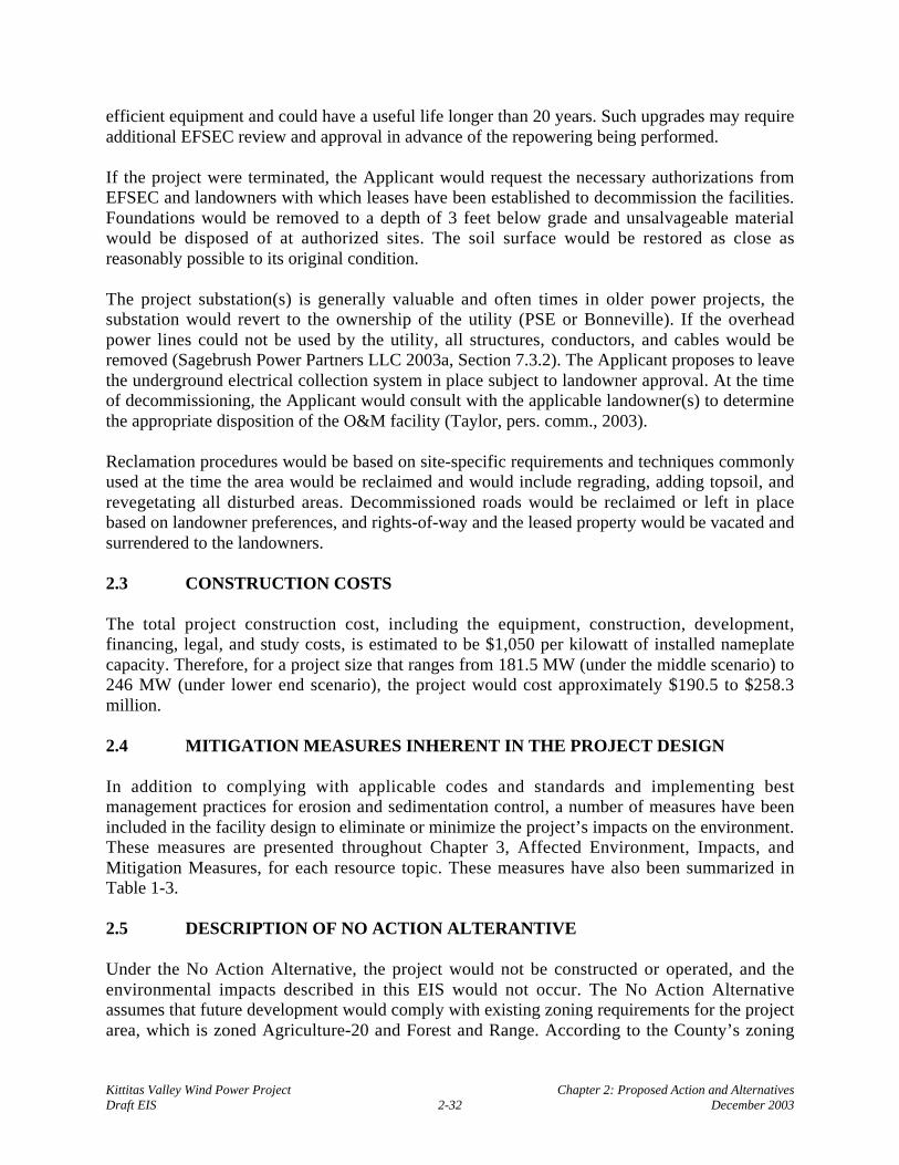
Kittitas Valley Wind Power Project Chapter 2: Proposed Action and AlternativesDraft EIS 2-32 December 2003
efficient equipment and could have a useful life longer than 20 years. Such upgrades may requireadditional EFSEC review and approval in advance of the repowering being performed.
If the project were terminated, the Applicant would request the necessary authorizations fromEFSEC and landowners with which leases have been established to decommission the facilities.Foundations would be removed to a depth of 3 feet below grade and unsalvageable materialwould be disposed of at authorized sites. The soil surface would be restored as close asreasonably possible to its original condition.
The project substation(s) is generally valuable and often times in older power projects, thesubstation would revert to the ownership of the utility (PSE or Bonneville). If the overheadpower lines could not be used by the utility, all structures, conductors, and cables would beremoved (Sagebrush Power Partners LLC 2003a, Section 7.3.2). The Applicant proposes to leavethe underground electrical collection system in place subject to landowner approval. At the timeof decommissioning, the Applicant would consult with the applicable landowner(s) to determinethe appropriate disposition of the O&M facility (Taylor, pers. comm., 2003).
Reclamation procedures would be based on site-specific requirements and techniques commonlyused at the time the area would be reclaimed and would include regrading, adding topsoil, andrevegetating all disturbed areas. Decommissioned roads would be reclaimed or left in placebased on landowner preferences, and rights-of-way and the leased property would be vacated andsurrendered to the landowners.
2.3 CONSTRUCTION COSTS
The total project construction cost, including the equipment, construction, development,financing, legal, and study costs, is estimated to be $1,050 per kilowatt of installed nameplatecapacity. Therefore, for a project size that ranges from 181.5 MW (under the middle scenario) to246 MW (under lower end scenario), the project would cost approximately $190.5 to $258.3million.
2.4 MITIGATION MEASURES INHERENT IN THE PROJECT DESIGN
In addition to complying with applicable codes and standards and implementing bestmanagement practices for erosion and sedimentation control, a number of measures have beenincluded in the facility design to eliminate or minimize the project’s impacts on the environment.These measures are presented throughout Chapter 3, Affected Environment, Impacts, andMitigation Measures, for each resource topic. These measures have also been summarized inTable 1-3.
2.5 DESCRIPTION OF NO ACTION ALTERANTIVE
Under the No Action Alternative, the project would not be constructed or operated, and theenvironmental impacts described in this EIS would not occur. The No Action Alternativeassumes that future development would comply with existing zoning requirements for the projectarea, which is zoned Agriculture-20 and Forest and Range. According to the County’s zoning

Kittitas Valley Wind Power Project Chapter 2: Proposed Action and AlternativesDraft EIS 2-33 December 2003
code, the Agriculture-20 zone is dominated by farming, ranching, and rural lifestyles, andpermitted uses include residential and agriculture and forestry practices. Permitted uses in theForest and Range zone include logging, mining, quarrying, and agricultural practices, as well asresidential uses (Kittitas County 1991). However, if the proposed project is not constructed, it islikely that the region’s need for power would be addressed by the development of a gas-firedcombustion turbine. Such development could occur at conducive locations throughout the stateof Washington. Because constructing and operating a gas-fired combustion turbine is apredictable consequence of not building the project, it is considered a predictable outcome of theNo Action Alternative (Bonneville et al. 2002).
Because the project has a nameplate capacity of approximately 181.5 MW (under the anticipatedmiddle scenario) and is expected to have a 33% net capacity factor, a natural gas-firedcombustion turbine would have to generate 60 average MW of energy to replace an equivalentamount of power generated by the project. (An average MW or “aMW” is the average amount ofenergy supplied over a specified period of time, in contrast to “MW,” which indicates themaximum or peak output [capacity] that can be supplied for a short period.) Table 2-9 presentsthe basic parameters of a hypothetical 60 aMW natural gas-fired combustion turbine. Thehypothetical combustion turbine could either be a new facility or an expansion of an existingfacility.
Table 2-9: Potential Annual Requirements of Energy Generation for a 60-AverageMegawatt Natural-Gas-Fired Combined-Cycle Combustion Turbine
Acreage Requirements Onshore Gas Extraction Transportation Generation1
Permanent (acres) NQ NQ 14Temporary (acres) NQ NQ N/AEmploymentConstruction (employees/year) 1.74 27 130Operations (employees per year) 0.18 0.78 9Water Resources
Consumption (acre-feet) N/A N/A 204Discharge (acre-feet) 0.348 (drilling mud) N/A 0.486
Air Pollutant Emissions2
Sulfur oxides (tons) 57 0.024 1.8Oxides of nitrogen (tons) 3.36 15.96 348.6Particulate (tons) 0.078 N/A 1.8Carbon dioxide (tons) 0 N/A 234,297Carbon monoxide (tons) 0 N/A 133.8
Source: Bonneville and U.S. Department of Energy 1993N/A = not applicableNQ = not quantified1 Acreage and employment estimates assume 65% capacity factor.2 Emission estimates are based on 1993 data; correcting for technology improvements in emissions control, projected
generation emissions are anticipated to be lower. See Section 3.11, Air Quality, for further discussion.
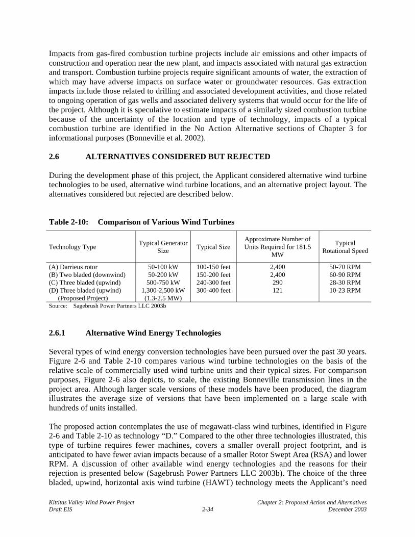
Kittitas Valley Wind Power Project Chapter 2: Proposed Action and AlternativesDraft EIS 2-34 December 2003
Impacts from gas-fired combustion turbine projects include air emissions and other impacts ofconstruction and operation near the new plant, and impacts associated with natural gas extractionand transport. Combustion turbine projects require significant amounts of water, the extraction ofwhich may have adverse impacts on surface water or groundwater resources. Gas extractionimpacts include those related to drilling and associated development activities, and those relatedto ongoing operation of gas wells and associated delivery systems that would occur for the life ofthe project. Although it is speculative to estimate impacts of a similarly sized combustion turbinebecause of the uncertainty of the location and type of technology, impacts of a typicalcombustion turbine are identified in the No Action Alternative sections of Chapter 3 forinformational purposes (Bonneville et al. 2002).
2.6 ALTERNATIVES CONSIDERED BUT REJECTED
During the development phase of this project, the Applicant considered alternative wind turbinetechnologies to be used, alternative wind turbine locations, and an alternative project layout. Thealternatives considered but rejected are described below.
Table 2-10: Comparison of Various Wind Turbines
Technology TypeTypical Generator
SizeTypical Size
Approximate Number ofUnits Required for 181.5
MW
TypicalRotational Speed
(A) Darrieus rotor 50-100 kW 100-150 feet 2,400 50-70 RPM(B) Two bladed (downwind) 50-200 kW 150-200 feet 2,400 60-90 RPM(C) Three bladed (upwind) 500-750 kW 240-300 feet 290 28-30 RPM(D) Three bladed (upwind)
(Proposed Project)1,300-2,500 kW(1.3-2.5 MW)
300-400 feet 121 10-23 RPM
Source: Sagebrush Power Partners LLC 2003b
2.6.1 Alternative Wind Energy Technologies
Several types of wind energy conversion technologies have been pursued over the past 30 years.Figure 2-6 and Table 2-10 compares various wind turbine technologies on the basis of therelative scale of commercially used wind turbine units and their typical sizes. For comparisonpurposes, Figure 2-6 also depicts, to scale, the existing Bonneville transmission lines in theproject area. Although larger scale versions of these models have been produced, the diagramillustrates the average size of versions that have been implemented on a large scale withhundreds of units installed.
The proposed action contemplates the use of megawatt-class wind turbines, identified in Figure2-6 and Table 2-10 as technology “D.” Compared to the other three technologies illustrated, thistype of turbine requires fewer machines, covers a smaller overall project footprint, and isanticipated to have fewer avian impacts because of a smaller Rotor Swept Area (RSA) and lowerRPM. A discussion of other available wind energy technologies and the reasons for theirrejection is presented below (Sagebrush Power Partners LLC 2003b). The choice of the threebladed, upwind, horizontal axis wind turbine (HAWT) technology meets the Applicant’s need
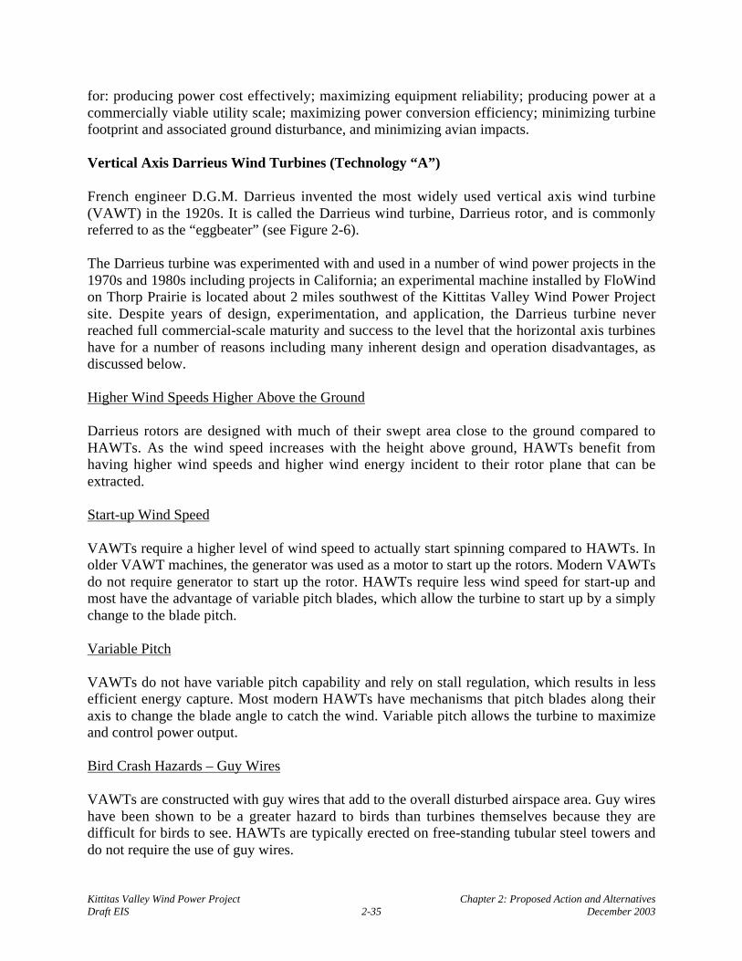
Kittitas Valley Wind Power Project Chapter 2: Proposed Action and AlternativesDraft EIS 2-35 December 2003
for: producing power cost effectively; maximizing equipment reliability; producing power at acommercially viable utility scale; maximizing power conversion efficiency; minimizing turbinefootprint and associated ground disturbance, and minimizing avian impacts.
Vertical Axis Darrieus Wind Turbines (Technology “A”)
French engineer D.G.M. Darrieus invented the most widely used vertical axis wind turbine(VAWT) in the 1920s. It is called the Darrieus wind turbine, Darrieus rotor, and is commonlyreferred to as the “eggbeater” (see Figure 2-6).
The Darrieus turbine was experimented with and used in a number of wind power projects in the1970s and 1980s including projects in California; an experimental machine installed by FloWindon Thorp Prairie is located about 2 miles southwest of the Kittitas Valley Wind Power Projectsite. Despite years of design, experimentation, and application, the Darrieus turbine neverreached full commercial-scale maturity and success to the level that the horizontal axis turbineshave for a number of reasons including many inherent design and operation disadvantages, asdiscussed below.
Higher Wind Speeds Higher Above the Ground
Darrieus rotors are designed with much of their swept area close to the ground compared toHAWTs. As the wind speed increases with the height above ground, HAWTs benefit fromhaving higher wind speeds and higher wind energy incident to their rotor plane that can beextracted.
Start-up Wind Speed
VAWTs require a higher level of wind speed to actually start spinning compared to HAWTs. Inolder VAWT machines, the generator was used as a motor to start up the rotors. Modern VAWTsdo not require generator to start up the rotor. HAWTs require less wind speed for start-up andmost have the advantage of variable pitch blades, which allow the turbine to start up by a simplychange to the blade pitch.
Variable Pitch
VAWTs do not have variable pitch capability and rely on stall regulation, which results in lessefficient energy capture. Most modern HAWTs have mechanisms that pitch blades along theiraxis to change the blade angle to catch the wind. Variable pitch allows the turbine to maximizeand control power output.
Bird Crash Hazards – Guy Wires
VAWTs are constructed with guy wires that add to the overall disturbed airspace area. Guy wireshave been shown to be a greater hazard to birds than turbines themselves because they aredifficult for birds to see. HAWTs are typically erected on free-standing tubular steel towers anddo not require the use of guy wires.

Kittitas Valley Wind Power Project Chapter 2: Proposed Action and AlternativesDraft EIS 2-36 December 2003
Figure 2-6:

Kittitas Valley Wind Power Project Chapter 2: Proposed Action and AlternativesDraft EIS 2-37 December 2003
Turbine Footprint
VAWTs are fitted with four sets of guy wires that span from the top of the central tower and areanchored in foundations. Including the tower base foundation, VAWTs require a total of fivefoundations all spread apart. The result is that the overall footprint and disturbed area for aVAWT is larger than that for a comparably sized HAWT. HAWTs on freestanding towers useonly one main foundation and have a smaller overall footprint.
Fatigue Life Cycles
Because of their design, VAWTs have higher fatigue life cycles than HAWTs, resulting in earlierand more frequent mechanical failures. As the VAWT rotor blades rotate through one fullrevolution, they pass upwind, downwind, and through two neutral zones (directly upwind of thetower and directly downwind of the tower). In contrast, the rotor blades on a HAWT do not passthrough similar upwind/downwind neutral zones, and their fatigue life cycles are lower.
Two-Bladed Downwind Wind Turbines (Technology “B”)
The most widely used vertical two-bladed wind turbines are of the downwind variety and are inthe size range of 50 to 200 kW. They are referred to as downwind since the blades are downwindof the supporting tower structure. Although there is continued experimentation with prototypewind turbines of this design of a larger scale (300-500 kW), they are not as well proven as thethree-bladed upwind technology. The two-bladed turbines require a higher rotational speed toreach optimal aerodynamic efficiency compared to a three-bladed turbine. Two-bladed turbinesand the rotors also are more difficult to balance and this, combined with the downwind towershadow, results in more mechanical failures compared to the three-bladed counterparts. As in thecase of Darrieus turbines, two-bladed downwind turbines use guy wires, with higher associatedavian impacts.
Smaller Three-Bladed Upwind Wind Turbines (Technology “C”)
Over the past 20 to 30 years, wind turbines have become larger and more efficient. Forcomparison purposes, a smaller 660 kW turbine is about 73% the height of a 1500-kW (1.5-MW), while its output is only 44% that of the 1.5 MW turbine. Compared to the proposed action,using smaller turbines in the 500 to 750 kW range would be less cost-effective and would requiremore than twice as many total turbines for an equivalent energy output. This would result inmore turbine foundations, a larger project footprint, and an overall higher impact on thesurrounding environment. Compared to the proposed project, use of such smaller turbines wouldalso result in a greater total RSA to produce the same amount of energy, and therefore a greaterincidence of avian impacts.

Kittitas Valley Wind Power Project Chapter 2: Proposed Action and AlternativesDraft EIS 2-38 December 2003
2.6.2 Alternative Wind Turbine Locations
Alternative Project Sites Considered by the Applicant
The siting of wind turbines is constrained by the need for a location with a sufficient windresource to allow the project to operate in a commercially and technically viable manner.Therefore, wind turbines must be sited in locations where data show there are sufficient windspeeds on a regular basis throughout the year (Bonneville et al. 2002).
The Applicant’s proposal for the Kittitas Valley Wind Power Project identified only theproposed project area for development. The study area was chosen primarily for its energeticwind resource suitable for producing electricity at competitive prices and access to several sets ofpower transmission lines that traverse the site and have adequate capacity to allow the wind-generated power to be integrated into the power grid. Other factors considered were siteaccessibility and surrounding land use compatibility. These combined factors rendered theproposed site the most practical and feasible from a technical and economic standpoint.
Other possible project site locations could jeopardize a project’s feasibility because of a lack ofsufficient wind resource (leading to operational problems and a lower return on investment)and/or remoteness from nearby transmission lines (which would require constructing a lengthytransmission line to interconnect with the power grid) (Bonneville et al. 2002). In Washington,the choice of potential project sites for producing wind-generated power is severely limited bythe lack of sites with adequate wind resource potential to produce electricity at competitiveprices. Compared with other states, Washington is ranked in the bottom tier in terms of windenergy potential (Pacific Northwest Laboratory 1991). Although there are other areas of the statepredicted to have a wind resource adequate for producing energy at competitive prices, long-termground-based measurements would be necessary to confirm the wind resource in these areas, andmany of the areas would not be suitable for wind power development because of siteinaccessibility (e.g., Cascade mountaintops) or incompatible land uses (e.g., the Yakima FiringRange). Based on wind measurements collected in the mid-1990s and from late 2001 to thepresent, the proposed project site has a proven wind resource suitable for producing electricity atcompetitive prices.
Another factor in identifying a viable site for a wind power project is access to existingtransmission lines with adequate outlet capacity. Wind power projects generally cannot absorbthe capital cost of constructing tens of miles of new transmission lines to interconnect with thegrid because of their generally smaller size and higher overall capital costs per MW of installedcapacity. The project site is crisscrossed by six sets of high voltage transmission lines, several ofwhich have adequate capacity and are of an appropriate voltage (230 to 287 kV) for a project ofthis size (181.5 to 246 MW).
To address scoping comments regarding the viability of other sites suitable for wind projectdevelopment, Section 2.7 below addresses other potential sites in Kittitas County, and whethersuch sites are reasonably available to Sagebrush Power Partners LLC.

Kittitas Valley Wind Power Project Chapter 2: Proposed Action and AlternativesDraft EIS 2-39 December 2003
Alternative Project Layout
In siting the individual turbines within strings at the project site, the same factors that were usedin choosing the study area were considered. The turbines have been sited to minimizeenvironmental effects to the greatest extent possible while maintaining the commercial viabilityof the project. Mitigation is identified in this EIS to further reduce and avoid potential impacts.
An alternative layout of individual turbines and turbine strings in the project area (referred to asAlternative A) was evaluated during the early stages of project development and wassubsequently refined to reduce potential impacts; the resulting layout defines the proposedaction. Alternative A was rejected for further consideration by the Applicant because of itshigher environmental impacts. A summary of Alternative A is presented below (SagebrushPower Partners LLC 2003b). The discussion below is limited to the “most likely” choice ofturbine size.
Alternative A is composed of 174 wind turbine generators that would disrupt an approximatefootprint of 105 acres (compared to approximately 93 acres for the proposed action) (Figure 2-7).Alternative A would extend several miles to the west of the proposed project area, across SwaukCreek to the western edge of Lookout Mountain. Alternative A would require constructingapproximately 28 miles of new and upgraded access roads (2 miles greater than under theproposed action) and about 5 miles of overhead electrical power lines (more than double theamount compared to the proposed action).
The larger permanent footprint covered by Alternative A would result in a greater magnitude ofimpacts on footprint-driven environmental resources, including land use conversion, area ofvisual disturbance, habitat loss, cultural resources disturbance, and construction truck trips. Forexample, Alternative A would generate 2,200 more construction truck trips than the proposedaction. Alternative A also would result in potential interference to directional microwavetelecommunication systems such as television and radio signals caused by eight turbines locatedon the edge of Lookout Mountain.
Compared to the proposed action, the additional turbines considered under Alternative A wouldlikely result in additional wildlife impacts in terms of overall avian and bat mortality. Nine of the174 turbines proposed under Alternative A would be located within three-quarters of a mile ofthe Yakima River. The proximity of turbines to the Yakima River could cause higher (perturbine) waterfowl and eagle mortality.
For example, compared to the proposed action, bird and bat mortality impacts would be greaterby approximately 40%. A range of approximately zero to seven raptor fatalities per year couldoccur if 174 turbines were constructed, an increase of approximately two raptor fatalities peryear over predictions under the proposed action. It is also estimated that approximately 70 to 430birds may be killed annually, an increase of 20 to 130 passerine fatalities each year compared tothe proposed action. It is further estimated that approximately 350 bats may be killed annually,an increase of approximately 110 bat fatalities each year compared to the proposed action .

Kittitas Valley Wind Power Project Chapter 2: Proposed Action and AlternativesDraft EIS 2-40 December 2003
Impacts such as bird and big game displacement would also increase as the number of turbinesand roads increases. Furthermore, the impacts in the western portion of the study area near thenine turbines under Alternative A may be higher on a per turbine basis than most other areas ofthe wind plant because of the current low levels of human disturbance in that area. More elk andmule deer were observed in the western portion of the wildlife baseline study area, probablybecause of the lower levels of human disturbance.
2.7 CONSIDERATION OF OFFSITE ALTERNATIVES
Through the scoping process for this project, EFSEC received requests that alternative offsitelocations be considered in the EIS. EFSEC has coordinated the evaluation of alternative siteswith Kittitas County, allowing both agencies and the public to benefit from the informationprovided regarding other potential sites. The analysis discussed in additional detail belowconcludes that although other sites for wind power generation may exist in Kittitas County, nonewould satisfy the test for availability or practicability for the Sagebrush Power Partners LLCproposal.
2.7.1 Process for Identifying Offsite Alternatives
This section describes the approach used for defining offsite alternatives for evaluation in theEIS. The approach includes the following steps: (1) consideration of SEPA requirements foralternatives; (2) definition of site selection/suitability criteria, which are based on the physical,technological and practical requirements of wind power generation facilities; (3) site screening,which involved application of the site selection/suitability criteria to the characteristics ofnumerous potential sites; and (4) identification of sites which could meet the criteria forsuitability. Kittitas County and its EIS consultants developed the criteria and site screeningprocess in coordination with EFSEC. Information regarding potential sites was provided byenXco and Desert Claim Wind Power LLC, the proponent for the Desert Claim Wind PowerProject, and by Sagebrush Power Partners LLC and Wind Ridge Power Partners LLC, theapplicants for the Kittitas Valley and Wild Horse Wind Power Projects, respectively.
SEPA Requirements
The State Environmental Policy Act requires that “reasonable alternatives” be considered by thelead agency under certain circumstances. When a proposal is made for a private project on aspecific site, the lead agency is required only to evaluate the no action alternative plus otherreasonable alternatives for achieving the proposal’s objective on the same site (WAC 197-11-440(5) (d). The same SEPA requirements however requires that an analysis of reasonablealternatives be conducted when the proposal includes a rezone, unless the rezone is for a useallowed in an existing comprehensive plan that was adopted after review under SEPA.
In general, alternatives considered under SEPA must be “reasonable,” which is defined to meanthat they can feasibly attain or approximate a proposal’s objectives at lower environmental cost(WAC 197-11-440 [5][b]). The word reasonable also limits the number and range of alternatives,and the amount of detailed analysis required under SEPA (WAC 197-11-440 [b] [i-ii]). The lead
Kittitas Valley Wind Power Project Chapter 2: Proposed Action and AlternativesDraft EIS 2-41 December 2003
agency may also limit alternatives to sites on which it has the authority to control impactsthrough the imposition of mitigation measures (WAC 197-11-440 [b] [iii]).
The Applicant’s objectives for the KVWPP are identified in Section 1.4.1 of the Draft EIS. Theyinclude developing a commercially viable wind energy facility with a total nameplate capacitybetween 181.5 and 246 MW using between 82 and 150 turbines, with associated project supportfacilities. To achieve this objective, the project site should be on large parcels and be free ofsignificant environmental constraints, such as parks and recreation areas, and land owners mustbe willing to enter into long-term leases. The Applicant must also meet the applicablecertification requirements set out in EFSEC laws and rules.
Consideration of alternatives has been limited to sites within Kittitas County, based on theCounty’s authority to impose its adopted review process and to control direct and indirectenvironmental impacts (WAC 197-11-440 [b] [iii]), and the focus of EFSEC’s SEPA review onthe local county environment that could be most likely affected.
Site Selection and Suitability Criteria
Site selection criteria were developed based on information provided by wind energy developers(enXco and Zilkha Renewable Energy), and a review of published information regarding sitingwind energy facilities (e.g., Wind Energy – How Does It Work, AWEA 2002a; 10 Steps inBuilding a Wind Farm, AWEA 2002b; Patrick Mazza, Wind: A New Economic Opportunity forRural Communities, 2002; Basic Principles of Wind Energy Evaluation, AWEA 1998; and WindEnergy Resources, National Wind Coordinating Committee 1997). The objective of the researchwas to identify the actual, not hypothetical, criteria that are typically used by developers toidentify and investigate potential sites and to determine their suitability for wind facilities. Thefollowing five key criteria were identified: (1) sufficient wind resource (the most important); (2)proximate/adequate transmission facilities; (3) large land area; (4) absence of significantenvironmental constraints; and (5) property owner interest. Each criterion is considered essential,and failure of a site with respect to any one criterion is considered to be a “fatal flaw” that wouldmake a wind power facility unfeasible at that site. The criteria are discussed further below; theexperience of the Desert Claim and Kittitas Valley Wind Power Project proposals is used toprovide context where appropriate.
(1) Sufficient wind resource. The most important criterion for siting a wind power facility is, ofcourse, sufficient commercially viable wind. Sites that do not possess sufficient wind are notconsidered further by prospective developers, regardless of other characteristics. In Washington,sites with a minimum average wind speed of 13 to 17 mph (Wind Classes 3-4) are desired tosupport a commercially viable wind energy facility. Given the current energy market conditionsin the Northwest and the characteristics of current wind energy proposals, an average wind speedof 15 to 17 mph appears to be the lower range of economic viability for a site. Sites with averagespeeds greater than 17 mph (Wind Classes 5 and above) are most desirable, but such sites inWashington are generally found in areas not conducive to wind power development, includingmountain peaks and off-shore in the Pacific Ocean. Since the energy that can be derived forpower generation from the wind is proportional to the cube of the wind speed, even a slightincrease in wind results in a large increase in energy production; this also results in a reduction in

Kittitas Valley Wind Power Project Chapter 2: Proposed Action and AlternativesDraft EIS 2-42 December 2003
the production cost of electricity (AWEA 2002a). Developers typically rely on published windenergy maps to initially identify regions or large areas with sufficient wind resources. They thenconduct more detailed site-specific meteorological (and environmental) studies, typically over 1to 2 years. The Wind Energy Resource Atlas of the United States (U.S. Department of Energy1986) identifies the Ellensburg corridor as having Class 3, 4 and 5 winds. (Also seewww.windpowermaps.org).
Both enXco and Sagebrush Power Partners LLC conducted additional meteorological studies andsite visual surveys to further narrow their search for potential wind energy facility sites inKittitas County to between four and five areas/sites with sufficient wind resources. Once apotential site/area was identified, meteorological data were used, along with information onnatural conditions and environmental features, to determine an optimal configuration of windturbines. A computer model aids in this siting process for each individual turbine (referred to as“micro-siting”) for a specific potential project site.
(2) Proximity to existing transmission facilities with adequate capacity. Wind energy projectsmust connect to an electric transmission line to deliver power to the regional power system. Themost important transmission-related factors considered by developers in project locationdecisions are the adequacy of existing transmission facilities (i.e., the availability of unusedcapacity on existing lines), and the distance from the project site to a transmission line. The needto either upgrade a regional transmission facility or to build an offsite project transmission linemore than about 10 miles (or less, depending upon the capacity of the project) to interconnect toan existing line can make a site financially infeasible. An interconnection agreement with theutility that owns the transmission line(s) is typically negotiated during development of the windproject and after the land is secured.
Existing transmission facilities located in the northern portion of the Kittitas Valley are ownedand operated by Bonneville (five 230 kV to 500 kV lines, and one 115 kV line) and PSE (one230 kV line and one 115 kV line). Transmission lines at voltages below 115 kV are not adequatefor connection of wind energy projects generating over 100 MW of electricity.
(3) Large land area. Some of the factors that bear on the size of a site needed for wind energyfacilities include the size of the project (in terms of power output and the size and number ofturbines); separation between turbines to ensure safety and efficient operation; dispersedpopulation; a prevalence of rural/agricultural activities (to minimize potential land use conflicts);sufficient setbacks from nearby residences, structures and public roads (to minimize potentialenvironmental impacts); and large undivided parcels of land (greater than 100 acres). Thesecriteria generally translate into project sites encompassing approximately 5,000 +/- acres of landfor a 180 MW wind project. However, developers typically begin their search by investigatingvery large study areas covering many thousands of acres (e.g., 20,000-50,000 acres or larger),and gradually focus in on a more defined area. In practice, a developer may be actively andsimultaneously considering, and applying the criteria to, several potential sites within the largerarea.
The Desert Claim (enXco) and Kittitas Valley (Sagebrush Power Partners LLC) proposals eachinvolve approximately 120 turbines producing roughly 180 MW of electric power. Each

Kittitas Valley Wind Power Project Chapter 2: Proposed Action and AlternativesDraft EIS 2-43 December 2003
developer independently defined an initial study area that included the entire Kittitas Valley(extending generally from Lookout Mountain on the west to the Columbia River on the east, andbetween the National Forest lands to the north and approximately Interstate 90 to the south).Each developer also conducted the studies necessary to determine desirable sites within thissearch area, then began to focus on smaller areas.
(4) Absence of significant environmental constraints. Wind energy developers try to avoid siteswith significant environmental constraints. The presence of constrained areas can increaseconstruction costs and make permitting more complex, time consuming, and uncertain. At thelevel of determining general site suitability and feasibility studies, characteristics taken intoaccount include the presence of parks or designated recreational lands, wildlife refuges, prevalentwetlands and/or sensitive habitat/species, significant cultural and archaeological resources, andconflicting land uses. Qualified developer personnel and consultants identify these resourcesthrough research of published sources, onsite investigations, and discussions with resourceagency staff.
(5) Property owner interest/property availability. Wind energy facilities are typically constructedon lands leased from property owners. As a practical matter, property owner support,responsiveness and willingness to enter into long-term leases are essential preconditions togaining the ability to propose a wind facility on a particular site. As to a particular privateapplicant (whether enXco or Sagebrush Power Partners LLC in an individual case), a site that isnot actually available for use would not meet that proposal’s objectives and would not, therefore,be a real or “reasonable alternative” (as defined in the SEPA Rules) as to that applicant.
Site Screening Process
The criteria identified above were applied to areas/sites within the Kittitas Valley. Sites locatedoutside Kittitas County were not considered to be “reasonable alternatives” per WAC 197-11-440 (b)(iii), and were not considered for evaluation in the EIS.
Four broad geographic areas, shown in Figure 2-8, were defined for investigation: west of US 97,east of US 97, Whiskey Dick Mountain, and south of Whiskey Dick/Boylston Mountains. Theseareas coincide with those identified in published information (e.g., the U.S. Department ofEnergy’s Wind Energy Resource Atlas) as having potentially viable wind resources. These areaswere explored by both enXco and Sagebrush Power Partners LLC to identify the sites of theirrespective proposals. Characteristics of each area relative to the site selection and suitabilitycriteria are summarized below.
West of US 97
The area west of US 97 contains four potential sites of interest for wind energy development –Springwood Ranch, the land south of Lookout Mountain, Manastash Ridge, and the site beingproposed for the Kittitas Valley Wind Power Project.

Kittitas Valley Wind Power Project Chapter 2: Proposed Action and AlternativesDraft EIS 2-44 December 2003
Figure 2-7

Kittitas Valley Wind Power Project Chapter 2: Proposed Action and AlternativesDraft EIS 2-45 December 2003
Figure 2-8

Kittitas Valley Wind Power Project Chapter 2: Proposed Action and AlternativesDraft EIS 2-46 December 2003
Springwood Ranch
The Springwood Ranch is an approximately 3,600-acre property that has been proposed orconsidered for development several times over the past 15 years. A conceptual master plan for aresort on this site was developed in the late 1980s, but an application for development was neversubmitted. The site was considered as an offsite alternative for the MountainStar Master PlannedResort and was evaluated in the EIS for that proposal (Kittitas County 1999).
For a wind energy facility, the Springwood Ranch site satisfied some, but not all of the siteselection criteria and thus does not qualify as a “reasonable alternative.” Sufficient wind resourceis present, the site is in single ownership, and environmental constraints are not extreme.However, transmission facilities are not currently accessible to the site. Site size, configuration,and terrain would also likely limit the number of turbines that could be sited and, consequently,the amount of power that could be produced falls well short of the proponent’s objective. Theproperty owner, a foreign corporation, did not support wind power and was not interested indiscussing leasing to accommodate a wind power facility. The site would not, therefore, meet theproponent’s project objectives. Nevertheless, this site is discussed in more detail in Section 2.7.3.
South of Lookout Mountain
The area south of Lookout Mountain includes approximately 2,600 acres of the Swauk ValleyRanch. Sufficient wind resource is present and environmental constraints are not extreme. In2001, enXco evaluated this area and met with a group of local property owners. This site failedthe site selection criteria because the property owners were not interested in participating in awind energy project.
Manastash Ridge
The Manastash Ridge area, south of I-90 and west of the Yakima River, also has sufficient windresource to be of interest for development. Much of this area consists of the L.T. MurrayWildlife Recreation Area, however, which encompasses approximately 106,000 acres and ismanaged by WDFW. Adjacent lands include the Wenatchee National Forest on the west and theOak Creek Wildlife Area (also managed by WDFW) on the south. The significant wildlife valuesand recreational use of this area would not satisfy the siting criteria related to environmentalconstraints. Also, this area is not adjacent to adequate transmission lines, and any project locatedin this area would require construction of a relatively long offsite project transmission line toreach existing transmission lines.
Kittitas Valley Site
The Kittitas Valley site is located both west and east of US 97. It is the subject of in-depth studyin this EIS. Given that the Kittitas Valley site is the subject of the active application bySagebrush Power Partners LLC (who has exclusive rights to wind energy development on thesite through agreements with landowners), the site is not available to enXco, does not meet theirproposal’s objectives, and is not a practical or reasonable alternative to the Desert Claim project.
Kittitas Valley Wind Power Project Chapter 2: Proposed Action and AlternativesDraft EIS 2-47 December 2003
East of US 97
The area east of US 97 generally satisfied all suitability criteria for wind energy development.Both enXco and Sagebrush Power Partners LLC identified respective sites (or portions of sites)within this area, and developed wind power proposals based on those sites.
A portion of the Kittitas Valley site, discussed previously, is located east of US 97. The DesertClaim site, proposed by Desert Claim Wind Power LLC, a Washington company wholly ownedand managed by enXco, is located approximately 8 miles northwest of Ellensburg. Desert ClaimWind Power LLC submitted an application for development of a wind energy facility on this siteto Kittitas County in January 2003. The proposal is for a maximum of 120 wind turbines (at 1.5MW each) producing a total of at least 180 MW of power, located on approximately 5,237 acresof privately-owned land in eight parcels.
Given that the Desert Claim site is the subject of an active application before Kittitas County byDesert Claim Wind Power LLC (who has exclusive rights to wind energy development on thesite through agreements with landowners), the site is not available to Sagebrush Power PartnersLLC, does not meet their proposal’s objectives, and is not a practical or reasonable alternative tothe project. The Draft EIS for the Desert Claim project is expected to be published and availablefor review contemporaneous with the Kittitas Valley Wind Power Project EIS. Decision makersand the public will, therefore, have the ability to review environmental information about theKittitas Valley site and compare it to the Desert Claim site, albeit in a separate document. Thecumulative effects of the Desert Claim project are considered (along with those of the WildHorse proposal) later in this EIS.
Whiskey Dick Mountain
This is a large area east of Ellensburg and north of I-90, centered on Whiskey Dick Mountain.The area east and northeast of Whiskey Dick Mountain contains the Schaake, Quilomene, andColockum Wildlife Areas. The ownership of these lands by WDFW and potential conflicts withwildlife and recreational values of these lands could make them unsuitable for wind energydevelopment. The area west of Whiskey Dick, which quickly drops to the Valley floor, shows apoor wind resource, making it not commercially viable based on historic meteorological data forthis area.
An area of approximately 26,000 acres centered on Whiskey Dick Mountain is owned by twoparties controlled by the same group. This area contains sufficient wind resource, has adequatetransmission facilities near the site, and is not characterized by wildlife area lands or readilyapparent major environmental constraints. Zilkha Renewable Energy executed an agreementwith owners of approximately 8,000 acres within this area and, through its wholly ownedcompany, Wind Ridge Power Partners LLC, submitted a request for a Potential Site Study toEFSEC in July 2003. The proposal would include approximately 110 to 120 wind turbines andwould generate approximately 180 MW of power. Because Wind Ridge Power Partners LLC hasalready indicated to EFSEC that an application for site certification would be brought forward tothe Council for this site, the Wild Horse Wind Power Project site would not meet the test of areasonable alternative for Sagebrush Power Partners LLC. A brief description of the Wild Horse

Kittitas Valley Wind Power Project Chapter 2: Proposed Action and AlternativesDraft EIS 2-48 December 2003
project is given below in Section 2.7.2. Additional specific information about the impacts of thisproposal are also available in Section 3.14, Cumulative Impacts, of this EIS.
South of Whiskey Dick/Boylston Mountains
The Boylston Mountains area, which is south of Whiskey Dick Mountain and east of the YakimaRiver, has sufficient wind resource but is comprised of lands that do not satisfy criteria related toland use or environmental constraints. The large area between the Yakima River and theColumbia River consists primarily of the Yakima Training Center, a federal military reservationadministered by the U.S. Department of Defense and actively used for military training.Construction and operation of a wind farm in the Boylston Mountains would conflict withongoing military operations on these lands and would not be allowed by the DefenseDepartment.
2.7.2 Wild Horse Site
As stated above, because Wind Ridge Power Partners LLC has indicated to EFSEC that anapplication for site certification would be brought forward to the Council for the Wild HorseWind Power Project site, this site would not meet the test of a reasonable alternative forSagebrush Power Partners LLC. A brief description of the Wild Horse project is provided below.
Location and Site Characteristics
The Wild Horse Wind Power Project is proposed on an approximately 5,000-acre site locatedabout 10 miles east of the town of Kittitas, on the eastern slopes of Whiskey Dick Mountain.With the exception of Whiskey Dick Mountain, much of the site consists of a relatively flatplateau with steep-sided drainages. Several creeks originate on the project site (Whiskey Dick,Skookumchuck, and Whiskey Jim); several other creeks and their tributaries are located on ornear the project site. The majority of the site consists of shrub-steppe habitat. No wetlands occuron the site, according to National Wetland Inventory (NWI) maps.
The proposed project area is zoned Forest and Range. It consists of open range land that iscurrently used for grazing. There are no residences on the project site, and none within 2 miles ofany proposed turbine location. The area surrounding the Wild Horse site is sparsely populated.The proposed route for the transmission feeder line passes near a few residences.
The Wild Horse project area (as proposed by Wind Ridge Power Partners LLC) includes threeparcels of State-owned land administered by DNR and totaling approximately 1,900 acres. Windturbines and associated facilities would be developed on these lands, through a lease agreementwith DNR.
Vehicle access to the site is via private road from Old Vantage Highway, at a pointapproximately 2 miles south of the project boundary and 10 miles east from Kittitas.

Kittitas Valley Wind Power Project Chapter 2: Proposed Action and AlternativesDraft EIS 2-49 December 2003
Wind Power Facilities
The proposed configuration of wind turbines on the Wild Horse site is shown in Figure 2-9. Theproposal would be comprised of between 83 to 125 wind turbines and associated facilities. Theproposal would generate between 125 and 249 MW of power depending on the size of turbineultimately chosen. Figure 2-9 presents a layout for a middle scenario of 1.5 MW nameplatecapacity turbines. Facilities and construction techniques would generally be as described inSection 2.2 for the proposed action. The project would interconnect to either the existingBonneville transmission line located approximately 4 miles west of the project site, or to theexisting PSE transmission line located approximately 5 miles southwest of the project site. (If theinterconnection were to the Bonneville system, the actual point of connection would be at theSchultz Substation farther to the northwest, although the Bonneville would build and operate thenew section of line that would run parallel to the existing Bonneville lines.)
The location of the project substation would depend upon the transmission system selected forinterconnection, pursuant to an agreement with Bonneville or PSE. Figure 2-9 shows twopotential substation locations. A location near the northwestern corner of the project site wouldbe used for the substation if interconnection were to the Bonneville transmission system, while asubstation location in the southwestern quadrant of the site would be used for a PSEinterconnection. An operations and maintenance facility would be constructed near the center ofthe project area.
A network of graveled project access roads would be constructed to provide vehicle access to allof the turbine locations, as described for the proposed action. Minor or major improvements toexisting primitive roads on the site would be implemented where possible, to minimizeconstruction of new roads. Figure 2-9 shows the configuration of the project road system inrelation to the turbines and other project facilities. Power collection cables (primarilyunderground) would generally follow the routes of the project access roads. Five permanentmeteorological towers and a communications tower would be constructed at various locations onthe project site.
Construction for the proposed Wild Horse project would occur over a 9-to-12 month period andis expected to be completed by the end of 2005. Gravel and other material needed for projectconstruction (for roads, pads, etc.) would be obtained from three quarries developed on the site.Figure 2-9 shows the location of a temporary batch plant that would be built to provide concretefor the project. Five construction laydown areas would be developed for temporary use.
The total area occupied by the turbines and associated permanent facilities would beapproximately 153 acres. The total area cleared/temporarily disturbed by construction activitieswould be approximately 309 acres. Once construction was completed, an estimated 10 to 14local workers would be employed to operate and maintain the facility.
The cumulative effects of the Wild Horse project are considered (along with those of the DesertClaim proposal) later in this EIS.

Kittitas Valley Wind Power Project Chapter 2: Proposed Action and AlternativesDraft EIS 2-50 December 2003
2.7.3 Springwood Ranch Site
As noted previously, this site is not a practical, reasonable alternative that is available toSagebrush Power Partners LLC. The Springwood Ranch site lacks accessible, adequatetransmission facilities and it does not meet the proponent’s objectives because it will not supporta 180 MW project due to site size, configuration, and terrain constraints that limit the number ofturbines that could be located on this property. Also, the owner of the Springwood Ranchexpressed lack of interest in discussing wind power development.
Although wind energy companies have investigated the prospects for wind energy developmentin the Springwood Ranch area, there has been no specific proposal for a wind energy project onthis site. The following project description is based on a conceptual layout for a wind powerproject on the Springwood Ranch site that was prepared by enXco, at Kittitas County’s request,specifically for their use in the Desert Claim EIS. A graphic of this conceptual layout is includedas Figure 2-10. Because this site would not represent a viable or reasonable alternative to theDesert Claim site for enXco, Kittitas County has not requested enXco to prepare complete plansfor a hypothetical project on this site. Therefore, Figure 2-10 identifies wind turbine andmeteorological tower locations, but does not include locations for access roads, power collectioncables, a substation, an operations and maintenance facility, or a transmission interconnection.These facilities would be required for a wind power project at this site, and their characteristicswould likely be similar to those defined in Section 2.2 for the same components of the proposedaction.
Location and Site Characteristics
Springwood Ranch is an approximately 3,610-acre site located approximately one-half milenorthwest from the town of Thorp and 10 miles northwest of Ellensburg. Springwood Ranch isbounded by I-90 (or Thorp Prairie Road) on the south and the Yakima River on the north. Thewestern end of the property abuts the Sunlight Waters community, in the Elk Heights area. TheIron Horse State Park/John Wayne Trail runs adjacent to or through the northern and easternedge of the site. The northern boundary of the L.T. Murray Wildlife Recreation Area, managedby WDFW, is located near the site but south of I-90.
The surrounding area is primarily rural/agricultural (designated Forest Multiple Use andAgriculture in the Kittitas County Comprehensive Plan, and zoned Agriculture-20 and Forest andRange). A small cluster of commercial uses is located at Thorp (designated an Urban GrowthNode [UGN] in the Kittitas County Comprehensive Plan). A ranch house and several accessorystructures and outbuildings are located onsite.

Kittitas Valley Wind Power Project Chapter 2: Proposed Action and AlternativesDraft EIS 2-51 December 2003
Figure 2-9

Kittitas Valley Wind Power Project Chapter 2: Proposed Action and AlternativesDraft EIS 2-52 December 2003
Figure 2-10

Kittitas Valley Wind Power Project Chapter 2: Proposed Action and AlternativesDraft EIS 2-53 December 2003
The topography of most of the site is gently rolling, but gives way to steep bluffs along a narrowcanyon that contains the Yakima River in this location. Taneum Creek runs in asouthwest/northeast direction through the eastern one-third of the site. The predominantly uplandterrain on the site drops approximately 200 feet to the valley along Taneum Creek, causing awind shadow over the eastern third of the property. Vegetation is predominantly shrub-steppeand grazed grasslands. Alfalfa and hay are grown on the site. NWI maps identify 20 wetlands onthe site, ranging in size from less than 3 acres to 8 acres. Most are associated with irrigationchannels or excavated ponds.
Habitat on the site would support animals adapted to open grasslands or the ecotone betweenforest and grasslands. The Yakima River in this vicinity supports one run of spring chinooksalmon. Several species of trout, including bull and steelhead, have been reported. LowerTaneum Creek has been historically used by resident trout and anadromous fish for spawningand rearing. Taneum Creek is listed as “water quality limited” surface waters (for temperatureand instream flow) under section 303 (d) of the federal Clean Water Act.
Wind Power Facilities
An approximate configuration for wind turbines is shown in Figure 2-10. Based on site size,meteorological conditions, and topography, and assuming the same sized turbines andapproximate spacing between turbines as for the proposed action, the Springwood Ranch sitecould accommodate approximately 40 to 45 turbines; Figure 2-10 shows locations for 43turbines. A smaller or greater number of turbines could potentially be accommodated based onmicro-siting. Using a 1.5 MW turbine, this number of turbines would generate approximately64.5 MW of electric power, which is less than half of the capacity of the proposed action underthe middle scenario. This reduced scale raises questions whether this could be a commerciallyviable site; in any case, it is below the Applicant’s objectives for a wind power facility (i.e., atleast 180 MW) and less than the quantity of wind energy that is currently being sought byregional utilities (e.g., in September 2003, PSE issued a draft request for proposals to acquireapproximately 150 MW of capacity from wind power). Connection to transmission facilities (forthe Bonneville lines) would require building a transmission line approximately 5 miles long,including crossing the Yakima River. Easements would also need to be acquired to travel acrossprivate properties located between the project site and the transmission line.
Other project facilities and construction techniques would be the same as described for theproposed action. The project substation would be located on the property, while a switchyardwould be located at the interconnect point. Project access roads would be similar in design to theproposed action, but would be proportionally less in terms of total distance and disturbance.Based on corresponding unit factors for the various project components, the total area disturbedby construction activities for this alternative site would be approximately 125 acres. The totalarea permanently occupied by project facilities in this case would be approximately 30 acres.The labor force required for construction and for long-term operation and maintenance of a 65-MW wind project on the Springwood Ranch site would be less than for the proposed action, butthe specific numbers or differences have not been estimated. The development of a project onthis site could also have greater impacts on wetlands and endangered fish species. Avian impactscannot be assessed without the support of a detailed study, however, they could be lower, since

Kittitas Valley Wind Power Project Chapter 2: Proposed Action and AlternativesDraft EIS 2-54 December 2003
less turbines would be constructed. Socioeconomic impacts on the County would be lowerbecause of both the smaller size of construction force required, and the lower capital cost of theproject as a whole.
2.8 BENEFITS OR DISADVANTAGES OF RESERVING PROJECT APPROVALFOR A LATER DATE
The disadvantages of reserving project approval for a later date would be continued reliance on aconstrained regional energy and capacity system. Delays in addressing the need for additionalpower resources in the region would do nothing to solve current supply shortfalls for electricalpower. Reserving project approval for a later date would delay all impacts of the project,including direct, indirect, and cumulative impacts. Delays might also result in construction andoperation of new gas-fired power plants to meet demand growth, which would involve additionalenvironmental impacts. Advantages of reserving project approval to a later date may include abetter understanding of its energy benefits and its potential environmental consequences,particularly related to issues of controversy such as the project’s effects on property values andits overall benefits to the local economy.


![Lecture 2: Implementation Alternatives & Concurrent · PDF fileLecture 2: Implementation Alternatives & Concurrent Programming [RTCS Ch. 3] • Implementation Alternatives • Processes](https://static.fdocuments.net/doc/165x107/5aaf392a7f8b9a3a038d1a29/lecture-2-implementation-alternatives-concurrent-2-implementation-alternatives.jpg)


