CHAPTER 19 CONCRETE - Home | ICC · PDF file · 2011-11-15CHAPTER 19 CONCRETE...
22
CHAPTER 19 CONCRETE SECTION 1901 GENERAL 1901.1 Scope. The provisions of this chapter shall govern the materials, quality control, design and construction of concrete used in structures. Exception: Buildings and structures located within the high-velocity hurricane zone shall comply with the provi- sions of Sections 1917 and 1919 through 1929. 1901.2 Plain and reinforced concrete. Structural concrete shall be designed and constructed in accordance with the requirements of this chapter and ACI 318 as amended in Sec- tion 1908 of this code. Except for the provisions of Sections 1904 and 1910, the design and construction of slabs on grade shall not be governed by this chapter unless they transmit verti- cal loads or lateral forces from other parts of the structure to the soil. 1901.3 Source and applicability. The format and subject mat- ter of Sections 1902 through 1907 of this chapter are patterned after, and in general conformity with, the provisions for struc- tural concrete in ACI 318. 1901.4 Construction documents. The construction docu- ments for structural concrete construction shall include: 1. The specified compressive strength of concrete at the stated ages or stages of construction for which each concrete element is designed. 2. The specified strength or grade of reinforcement. 3. The size and location of structural elements, reinforce- ment and anchors. 4. Provision for dimensional changes resulting from creep, shrinkage and temperature. 5. The magnitude and location of prestressing forces. 6. Anchorage length of reinforcement and location and length of lap splices. 7. Type and location of mechanical and welded splices of reinforcement. 8. Details and location of contraction or isolation joints specified for plain concrete. 9. Minimum concrete compressive strength at time of posttensioning. 10. Stressing sequence for posttensioning tendons. 11. For structures assigned to Seismic Design Category D, E or F, a statement if slab on grade is designed as a structural diaphragm (see Section 21.12.3.4 of ACI 318). 1901.5 Special inspection. Reserved. SECTION 1902 DEFINITIONS 1902.1 General. The words and terms defined in ACI 318 shall, for the purposes of this chapter and as used elsewhere in this code for concrete construction, have the meanings shown in ACI 318 as modified by Section 1908.1.1. SECTION 1903 SPECIFICATIONS FOR TESTS AND MATERIALS 1903.1 General. Materials used to produce concrete, concrete itself and testing thereof shall comply with the applicable stan- dards listed in ACI 318. Where required, special inspections and tests shall be in accordance with Chapter 17. 1903.2 Glass fiber reinforced concrete. Glass fiber rein- forced concrete (GFRC) and the materials used in such con- crete shall be in accordance with the PCI MNL 128 standard. SECTION 1904 DURABILITY REQUIREMENTS 1904.1 Water-cementitious materials ratio. Where maximum water-cementitious materials ratios are specified in ACI 318, they shall be calculated in accordance with ACI 318, Section 4.1. 1904.2 Exposure categories and classes. Concrete shall be assigned to exposure classes in accordance with ACI 318, Sec- tion 4.2, based on: 1. Exposure to freezing and thawing in a moist condition or deicer chemicals; 2. Exposure to sulfates in water or soil; 3. Exposure to water where the concrete is intended to have low permeability; and 4. Exposure to chlorides from deicing chemicals, salt, saltwater, brackish water, seawater or spray from these sources, where the concrete has steel reinforcement. 1904.3 Concrete properties. Concrete mixtures shall conform to the most restrictive maximum water-cementitious materials ratios and minimum specified concrete compressive strength requirements of ACI 318, Section 4.3, based on the exposure classes assigned in Section 1904.2. Exception: For occupancies and appurtenances thereto in Group R occupancies that are in buildings less than four stories above grade plane, normal-weight aggregate con- crete is permitted to comply with the requirements of Table 2010 FLORIDA BUILDING CODE — BUILDING 19.1 Italics are used for text within Sections 1903 through 1908 of this code to indicate provisions that differ from ACI 318.
Transcript of CHAPTER 19 CONCRETE - Home | ICC · PDF file · 2011-11-15CHAPTER 19 CONCRETE...

CHAPTER 19
CONCRETE
SECTION 1901GENERAL
1901.1 Scope. The provisions of this chapter shall govern thematerials, quality control, design and construction of concreteused in structures.
Exception: Buildings and structures located within thehigh-velocity hurricane zone shall comply with the provi-sions of Sections 1917 and 1919 through 1929.
1901.2 Plain and reinforced concrete. Structural concreteshall be designed and constructed in accordance with therequirements of this chapter and ACI 318 as amended in Sec-tion 1908 of this code. Except for the provisions of Sections1904 and 1910, the design and construction of slabs on gradeshall not be governed by this chapter unless they transmit verti-cal loads or lateral forces from other parts of the structure to thesoil.
1901.3 Source and applicability. The format and subject mat-ter of Sections 1902 through 1907 of this chapter are patternedafter, and in general conformity with, the provisions for struc-tural concrete in ACI 318.
1901.4 Construction documents. The construction docu-ments for structural concrete construction shall include:
1. The specified compressive strength of concrete at thestated ages or stages of construction for which eachconcrete element is designed.
2. The specified strength or grade of reinforcement.
3. The size and location of structural elements, reinforce-ment and anchors.
4. Provision for dimensional changes resulting fromcreep, shrinkage and temperature.
5. The magnitude and location of prestressing forces.
6. Anchorage length of reinforcement and location andlength of lap splices.
7. Type and location of mechanical and welded splices ofreinforcement.
8. Details and location of contraction or isolation jointsspecified for plain concrete.
9. Minimum concrete compressive strength at time ofposttensioning.
10. Stressing sequence for posttensioning tendons.
11. For structures assigned to Seismic Design Category D,E or F, a statement if slab on grade is designed as astructural diaphragm (see Section 21.12.3.4 of ACI318).
1901.5 Special inspection. Reserved.
SECTION 1902DEFINITIONS
1902.1 General. The words and terms defined in ACI 318shall, for the purposes of this chapter and as used elsewhere inthis code for concrete construction, have the meanings shownin ACI 318 as modified by Section 1908.1.1.
SECTION 1903SPECIFICATIONS FOR TESTS AND MATERIALS
1903.1 General. Materials used to produce concrete, concreteitself and testing thereof shall comply with the applicable stan-dards listed in ACI 318. Where required, special inspectionsand tests shall be in accordance with Chapter 17.
1903.2 Glass fiber reinforced concrete. Glass fiber rein-forced concrete (GFRC) and the materials used in such con-crete shall be in accordance with the PCI MNL 128 standard.
SECTION 1904DURABILITY REQUIREMENTS
1904.1 Water-cementitious materials ratio. Where maximumwater-cementitious materials ratios are specified in ACI 318,they shall be calculated in accordance with ACI 318, Section 4.1.
1904.2 Exposure categories and classes. Concrete shall beassigned to exposure classes in accordance with ACI 318, Sec-tion 4.2, based on:
1. Exposure to freezing and thawing in a moist condition ordeicer chemicals;
2. Exposure to sulfates in water or soil;
3. Exposure to water where the concrete is intended to havelow permeability; and
4. Exposure to chlorides from deicing chemicals, salt,saltwater, brackish water, seawater or spray from thesesources, where the concrete has steel reinforcement.
1904.3 Concrete properties. Concrete mixtures shall conformto the most restrictive maximum water-cementitious materialsratios and minimum specified concrete compressive strengthrequirements of ACI 318, Section 4.3, based on the exposureclasses assigned in Section 1904.2.
Exception: For occupancies and appurtenances thereto inGroup R occupancies that are in buildings less than fourstories above grade plane, normal-weight aggregate con-crete is permitted to comply with the requirements of Table
2010 FLORIDA BUILDING CODE — BUILDING 19.1
Italics are used for text within Sections 1903 through 1908 of this code to indicate provisions that differ from ACI 318.

19.2 2010 FLORIDA BUILDING CODE — BUILDING
CONCRETE
TABLE 1904.3MINIMUM SPECIFIED COMPRESSIVE STRENGTH (f c)
TYPE OR LOCATION OF CONCRETE CONSTRUCTION
MINIMUM SPECIFIED COMPRESSIVE STRENGTH (f c at 28 days, psi)
Negligible exposure Moderate exposure Severe exposure
Basement wallsc and foundations not exposed to the weather 2,500 2,500 2,500a
Basement slabs and interior slabs on grade, except garage floorslabs 2,500 2,500 2,500a
Basement wallsc, foundation walls, exterior walls and othervertical concrete surfaces exposed to the weather 2,500 3,000b 3,000b
Driveways, curbs, walks, patios, porches, carport slabs, steps andother flatwork exposed to the weather, and garage floor slabs 2,500 3,000b, d 3,500b, d
For SI: 1 pound per square inch = 0.00689 MPa.a. Concrete in these locations that can be subjected to freezing and thawing during construction shall be of air-entrained concrete in accordance with Section
1904.4.1.b. Concrete shall be air entrained in accordance with Section 1904.4.1.c. Structural plain concrete basement walls are exempt from the requirements for exposure conditions of Section 1904.3 (see Section 1909.6.1).d. For garage floor slabs where a steel trowel finish is used, the total air content required by Section 1904.4.1 is permitted to be reduced to not less than 3 percent, pro-
vided the minimum specified compressive strength of the concrete is increased to 4,000 psi.
FIGURE 1904.3WEATHERING PROBABILITY MAP FOR CONCRETEa, b, c
a. Lines defining areas are approximate only. Local areas can be more or less severe than indicated by the region classification.b. A “severe” classification is where weather conditions encourage or require the use of deicing chemicals or where there is potential for a continuous presence of
moisture during frequent cycles of freezing and thawing. A “moderate” classification is where weather conditions occasionally expose concrete in the presence ofmoisture to freezing and thawing, but where deicing chemicals are not generally used. A “negligible” classification is where weather conditions rarely expose con-crete in the presence of moisture to freezing and thawing.
c. Alaska and Hawaii are classified as severe and negligible, respectively.

1904.3 based on the weathering classification (freezing andthawing) determined from Figure 1904.3 in lieu of therequirements of ACI 318, Table 4.3.1.
1904.4 Freezing and thawing exposures. Concrete that willbe exposed to freezing and thawing, in the presence of mois-ture, with or without deicing chemicals being present, shallcomply with Sections 1904.4.1 and 1904.4.2.
1904.4.1 Air entrainment. Concrete exposed to freezingand thawing while moist shall be air entrained in accordancewith ACI 318, Section 4.4.1.
1904.4.2 Deicing chemicals. For concrete exposed to freez-ing and thawing in the presence of moisture and deicingchemicals, the maximum weight of fly ash, other pozzolans,silica fume or slag that is included in the concrete shall notexceed the percentages of the total weight of cementitiousmaterials permitted by ACI 318, Section 4.4.2.
1904.5 Alternative cementitious materials for sulfate expo-sure. Alternative combinations of cementitious materials foruse in sulfate-resistant concrete to those listed in ACI 318,Table 4.3.1 shall be permitted in accordance with ACI 318,Section 4.5.1.
SECTION 1905CONCRETE QUALITY, MIXING AND PLACING
1905.1 General. The required strength and durability of con-crete shall be determined by compliance with the proportion-ing, testing, mixing and placing provisions of Sections1905.1.1 through 1905.13.
1905.1.1 Strength. Concrete shall be proportioned to pro-vide an average compressive strength as prescribed in Sec-tion 1905.3 and shall satisfy the durability criteria ofSection 1904. Concrete shall be produced to minimize thefrequency of strengths below f c as prescribed in Section1905.6.3. For concrete designed and constructed in accor-dance with this chapter, f c shall not be less than 2,500 psi(17.22 MPa). No maximum specified compressive strengthshall apply unless restricted by a specific provision of thiscode or ACI 318.
1905.2 Selection of concrete proportions. Concrete propor-tions shall be determined in accordance with the provisions ofACI 318, Section 5.2.
1905.3 Proportioning on the basis of field experienceand/or trial mixtures. Concrete proportioning determined onthe basis of field experience and/or trial mixtures shall be donein accordance with ACI 318, Section 5.3.
1905.4 Proportioning without field experience or trial mix-tures. Concrete proportioning determined without field expe-rience or trial mixtures shall be done in accordance with ACI318, Section 5.4.
1905.5 Average strength reduction. As data become avail-able during construction, it is permissible to reduce the amountby which the average compressive strength (f c) is required to
exceed the specified value of f c in accordance with ACI 318,Section 5.5.
1905.6 Evaluation and acceptance of concrete. The criteriafor evaluation and acceptance of concrete shall be as specifiedin Sections 1905.6.2 through 1905.6.5.
1905.6.1 Qualified technicians. Concrete shall be tested inaccordance with the requirements in Sections 1905.6.2through 1905.6.5. Qualified field testing technicians shallperform tests on fresh concrete at the job site, prepare speci-mens required for curing under field conditions, preparespecimens required for testing in the laboratory and recordthe temperature of the fresh concrete when preparing speci-mens for strength tests. Qualified laboratory techniciansshall perform all required laboratory tests.
1905.6.2 Frequency of testing. The frequency of conduct-ing strength tests of concrete and the minimum number oftests shall be as specified in ACI 318, Section 5.6.2.
Exception: When the total volume of a given class ofconcrete is less than 50 cubic yards (38 m3), strength testsare not required when evidence of satisfactory strength issubmitted to and approved by the building official.
1905.6.3 Strength test specimens. Specimens prepared foracceptance testing of concrete in accordance with Section1905.6.2 and strength test acceptance criteria shall complywith the provisions of ACI 318, Section 5.6.3.
1905.6.4 Field-cured specimens. Where required by thebuilding official to determine adequacy of curing and pro-tection of concrete in the structure, specimens shall be pre-pared, cured, tested and test results evaluated for acceptancein accordance with ACI 318, Section 5.6.4.
1905.6.5 Low-strength test results. Where any strengthtest (see ACI 318, Section 5.6.2.4) falls below the specifiedvalue of f c, the provisions of ACI 318, Section 5.6.5, shallapply.
1905.7 Preparation of equipment and place of deposit. Priorto concrete being placed, the space to receive the concrete andthe equipment used to deposit it shall comply with ACI 318,Section 5.7.
1905.8 Mixing. Mixing of concrete shall be performed inaccordance with ACI 318, Section 5.8.
1905.9 Conveying. The method and equipment for conveyingconcrete to the place of deposit shall comply with ACI 318,Section 5.9.
1905.10 Depositing. The depositing of concrete shall complywith the provisions of ACI 318, Section 5.10.
1905.11 Curing. The length of time, temperature and moistureconditions for curing of concrete shall be in accordance withACI 318, Section 5.11.
1905.12 Cold weather requirements. Concrete to be placedduring freezing or near-freezing weather shall comply with therequirements of ACI 318, Section 5.12.
2010 FLORIDA BUILDING CODE — BUILDING 19.3
CONCRETE
➡
➡

1905.13 Hot weather requirements. Concrete to be placedduring hot weather shall comply with the requirements of ACI318, Section 5.13.
SECTION 1906FORMWORK, EMBEDDED PIPES AND
CONSTRUCTION JOINTS
1906.1 Formwork. The design, fabrication and erection offorms shall comply with ACI 318, Section 6.1.
1906.2 Removal of forms, shores and reshores. The removalof forms and shores, including from slabs and beams (exceptwhere cast on the ground), and the installation of reshores shallcomply with ACI 318, Section 6.2.
1906.3 Conduits and pipes embedded in concrete. Conduits,pipes and sleeves of any material not harmful to concrete andwithin the limitations of ACI 318, Section 6.3, are permitted tobe embedded in concrete with approval of the registered designprofessional.
1906.4 Construction joints. Construction joints, includingtheir location, shall comply with the provisions of ACI 318,Section 6.4.
SECTION 1907DETAILS OF REINFORCEMENT
1907.1 Hooks. Standard hooks on reinforcing bars used inconcrete construction shall comply with ACI 318, Section 7.1.
1907.2 Minimum bend diameters. Minimum reinforcementbend diameters utilized in concrete construction shall complywith ACI 318, Section 7.2.
1907.3 Bending. The bending of reinforcement shall complywith ACI 318, Section 7.3.
1907.4 Surface conditions of reinforcement. The surfaceconditions of reinforcement shall comply with the provisionsof ACI 318, Section 7.4.
1907.5 Placing reinforcement. The placement of reinforce-ment, including tolerances on depth and cover, shall complywith the provisions of ACI 318, Section 7.5. Reinforcementshall be accurately placed and adequately supported beforeconcrete is placed.
1907.6 Spacing limits for reinforcement. The clear distancebetween reinforcing bars, bundled bars, tendons and ductsshall comply with ACI 318, Section 7.6.
1907.7 Concrete protection for reinforcement. The mini-mum specified concrete cover for reinforcement shall complywith Sections 1907.7.1 through 1907.7.8.
1907.7.1 Cast-in-place concrete (nonprestressed). Mini-mum specified concrete cover shall be provided for rein-forcement in nonprestressed, cast-in-place concreteconstruction in accordance with ACI 318, Section 7.7.1.
1907.7.2 Cast-in-place concrete (prestressed). The mini-mum specified concrete cover for prestressed andnonprestressed reinforcement, ducts and end fittings in
cast-in-place prestressed concrete shall comply with ACI318, Section 7.7.2.
1907.7.3 Precast concrete (manufactured under plantcontrol conditions). The minimum specified concretecover for prestressed and nonprestressed reinforcement,ducts and end fittings in precast concrete manufacturedunder plant control conditions shall comply with ACI 318,Section 7.7.3.
1907.7.4 Bundled bars. The minimum specified concretecover for bundled bars shall comply with ACI 318, Section7.7.4.
1907.7.5 Headed shear stud reinforcement. For headedshear stud reinforcement, the minimum specified concretecover shall comply with ACI 318, Section 7.7.5.
1907.7.6 Corrosive environments. In corrosive environ-ments or other severe exposure conditions, prestressed andnonprestressed reinforcement shall be provided with addi-tional protection in accordance with ACI 318, Section 7.7.6.
1907.7.7 Future extensions. Exposed reinforcement,inserts and plates intended for bonding with future exten-sions shall be protected from corrosion.
1907.7.8 Fire protection. When this code requires a thick-ness of cover for fire protection greater than the minimumconcrete cover in Section 1907.7, such greater thicknessshall be specified.
1907.8 Special reinforcement details for columns. Offsetbent longitudinal bars in columns and load transfer in structuralsteel cores of composite compression members shall complywith the provisions of ACI 318, Section 7.8.
1907.9 Connections. Connections between concrete framingmembers shall comply with the provisions of ACI 318, Section7.9.
1907.10 Lateral reinforcement for compression members.Lateral reinforcement for concrete compression members shallcomply with the provisions of ACI 318, Section 7.10.
1907.11 Lateral reinforcement for flexural members. Lat-eral reinforcement for compression reinforcement in concreteflexural members shall comply with the provisions of ACI 318,Section 7.11.
1907.12 Shrinkage and temperature reinforcement. Rein-forcement for shrinkage and temperature stresses in concretemembers shall comply with the provisions of ACI 318, Section7.12.
1907.13 Requirements for structural integrity. The detail-ing of reinforcement and connections between concrete mem-bers shall comply with the provisions of ACI 318, Section 7.13,to improve structural integrity.
19.4 2010 FLORIDA BUILDING CODE — BUILDING
CONCRETE
SECTION 1908MODIFICATIONS TO ACI 318
RESERVED
SECTION 1909STRUCTURAL PLAIN CONCRETE
1909.1 Scope. The design and construction of structural plainconcrete, both cast-in-place and precast, shall comply with theminimum requirements of Section 1909 and ACI 318, Chapter22, as modified in Section 1908.
1909.1.1 Special structures. For special structures, such asarches, underground utility structures, gravity walls andshielding walls, the provisions of this section shall governwhere applicable.
1909.2 Limitations. The use of structural plain concrete shallbe limited to:
1. Members that are continuously supported by soil, suchas walls and footings, or by other structural memberscapable of providing continuous vertical support.
2. Members for which arch action provides compressionunder all conditions of loading.
3. Walls and pedestals.
The use of structural plain concrete columns and structuralplain concrete footings on piles is not permitted. See Section1908.1.8 for additional limitations on the use of structural plainconcrete.
1909.3 Joints. Contraction or isolation joints shall be providedto divide structural plain concrete members into flexurally dis-continuous elements in accordance with ACI 318, Section 22.3.
1909.4 Design. Structural plain concrete walls, footings andpedestals shall be designed for adequate strength in accordancewith ACI 318, Sections 22.4 through 22.8.
Exception: For Group R-3 occupancies and buildings ofother occupancies less than two stories above grade planeof light-frame construction, the required edge thickness ofACI 318 is permitted to be reduced to 6 inches (152 mm),provided that the footing does not extend more than 4 inches(102 mm) on either side of the supported wall.
1909.5 Precast members. The design, fabrication, transporta-tion and erection of precast, structural plain concrete elementsshall be in accordance with ACI 318, Section 22.9.
1909.6 Walls. In addition to the requirements of this section,structural plain concrete walls shall comply with the applicablerequirements of ACI 318, Chapter 22.
1909.6.1 Basement walls. The thickness of exterior base-ment walls and foundation walls shall be not less than 71/2
inches (191 mm).
1909.6.2 Other walls. Except as provided for in Section1909.6.1, the thickness of bearing walls shall be not lessthan 1/24 the unsupported height or length, whichever isshorter, but not less than 51/2 inches (140 mm).
1909.6.3 Openings in walls. Not less than one No. 5 barshall be provided around window, door and similar sizedopenings. The bar shall be anchored to develop fy in tensionat the corners of openings.
SECTION 1910MINIMUM SLAB PROVISIONS
1910.1 General. The thickness of concrete floor slabs supporteddirectly on the ground shall not be less than 31/2 inches (89 mm).A 6-mil (0.006 inch; 0.15 mm) polyethylene vapor retarder withjoints lapped not less than 6 inches (152 mm) shall be placedbetween the base course or subgrade and the concrete floor slab,or other approved equivalent methods or materials shall be usedto retard vapor transmission through the floor slab.
Exception: A vapor retarder is not required:
1. For detached structures accessory to occupancies inGroup R-3, such as garages, utility buildings or otherunheated facilities.
2. For unheated storage rooms having an area of lessthan 70 square feet (6.5 m2) and carports attached tooccupancies in Group R-3.
3. For buildings of other occupancies where migrationof moisture through the slab from below will not bedetrimental to the intended occupancy of the building.
4. For driveways, walks, patios and other flatworkwhich will not be enclosed at a later date.
5. Where approved based on local site conditions.
1910.2 Joints. Concrete slabs on ground shall be providedwith joints in accordance with ACI 224.3R or other approvedmethods. Joints shall be designed by an architect or engineer.
Exception: Joints are not required in unreinforced plainconcrete slabs on ground or in slabs for one- and two-familydwellings complying with one of the following:
1. Concrete slabs on ground containing synthetic fiberreinforcement. Fiber lengths and dosage amountsshall comply with one of the following:
(a) Fiber lengths shall be 1/2 inch to 2 inches (13 to 51mm) in length. Dosage amounts shall be from0.75 to 1.5 pounds per cubic yard (0.45 to 0.89kg/m3) in accordance with the manufacturer’srecommendations. Synthetic fibers shall complywith ASTM C 1116. The manufacturer or sup-plier shall provide certification of compliancewith ASTM C 1116 when requested by the build-ing official; or,
(b) Fiber length shall be from 1/2 inch to 2 inches (13mm to 51 mm) in length, monofilament or fibril-lated. Dosage amounts shall be from 0.5 to 1.5pounds per cubic yard (0.30 to 0.89 kg/m3) toachieve minimum 40 percent reduction of plasticshrinkage cracking of concrete versus a controlmix in accordance with ICBO AC32. Independ-ent test results using minimum six (6) test speci-
2010 FLORIDA BUILDING CODE — BUILDING 19.5
CONCRETE
mens shall be provided to the building officialshowing compliance with ICBO A32. Syntheticfiber shall comply with ASTM C 1116, Para-graph 4.1.3, Type III. The manufacturer or sup-plier shall provide certification of compliancewith ASTM C 1116 when requested by buildingofficial.
2. Concrete slabs on ground containing 6 × 6 W1.4 ×W1.4 welded wire reinforcement fabric located in themiddle to the upper one-third of the slab. Welded wirereinforcement fabric shall be supported withapproved materials or supports at spacings not toexceed 3 feet (914 mm) or in accordance with themanufacturer’s specifications. Welded plain wirereinforcement fabric for concrete shall conform toASTM A 185, Standard Specification for SteelWelded Wire Reinforcement Fabric, Plain, for Con-crete Reinforcement.
SECTION 1911ANCHORAGE TO CONCRETE—ALLOWABLE STRESS DESIGN
1911.1 Scope. The provisions of this section shall govern theallowable stress design of headed bolts and headed studanchors cast in normal-weight concrete for purposes of trans-mitting structural loads from one connected element to theother. These provisions do not apply to anchors installed inhardened concrete. The bearing area of headed anchors shall benot less than one and one-half times the shank area. Wherestrength design is used, the design strength of anchors shall bedetermined in accordance with Section 1912. Bolts shall con-form to ASTM A 307 or an approved equivalent.
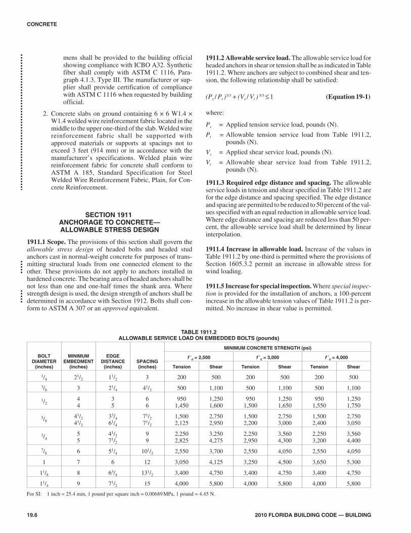
1911.2 Allowable service load. The allowable service load forheaded anchors in shear or tension shall be as indicated in Table1911.2. Where anchors are subject to combined shear and ten-sion, the following relationship shall be satisfied:
(Ps / Pt )5/3 + (Vs / Vt ) 5/3 ≤ 1 (Equation 19-1)
where:
Ps = Applied tension service load, pounds (N).
Pt = Allowable tension service load from Table 1911.2,pounds (N).
Vs = Applied shear service load, pounds (N).
Vt = Allowable shear service load from Table 1911.2,pounds (N).
1911.3 Required edge distance and spacing. The allowableservice loads in tension and shear specified in Table 1911.2 arefor the edge distance and spacing specified. The edge distanceand spacing are permitted to be reduced to 50 percent of the val-ues specified with an equal reduction in allowable service load.Where edge distance and spacing are reduced less than 50 per-cent, the allowable service load shall be determined by linearinterpolation.
1911.4 Increase in allowable load. Increase of the values inTable 1911.2 by one-third is permitted where the provisions ofSection 1605.3.2 permit an increase in allowable stress forwind loading.
1911.5 Increase for special inspection. Where special inspec-tion is provided for the installation of anchors, a 100-percentincrease in the allowable tension values of Table 1911.2 is per-mitted. No increase in shear value is permitted.
19.6 2010 FLORIDA BUILDING CODE — BUILDING
CONCRETE
TABLE 1911.2ALLOWABLE SERVICE LOAD ON EMBEDDED BOLTS (pounds)
BOLTDIAMETER
(inches)
MINIMUMEMBEDMENT
(inches)
EDGEDISTANCE
(inches)SPACING(inches)
MINIMUM CONCRETE STRENGTH (psi)
f c = 2,500 f c = 3,000 f c = 4,000
Tension Shear Tension Shear Tension Shear
1/4 21/2 11/2 3 200 500 200 500 200 500
3/8 3 21/4 41/2 500 1,100 500 1,100 500 1,100
1/244
35
66
9501,450
1,2501,600
9501,500
1,2501,650
9501,550
1,2501,750
5/841/241/2
33/461/4
71/271/2
1,5002,125
2,7502,950
1,5002,200
2,7503,000
1,5002,400
2,7503,050
3/455
41/271/2
99
2,2502,825
3,2504,275
2,2502,950
3,5604,300
2,2503,200
3,5604,400
7/8 6 51/4 101/2 2,550 3,700 2,550 4,050 2,550 4,050
1 7 6 12 3,050 4,125 3,250 4,500 3,650 5,300
11/8 8 63/4 131/2 3,400 4,750 3,400 4,750 3,400 4,750
11/4 9 71/2 15 4,000 5,800 4,000 5,800 4,000 5,800
For SI: 1 inch = 25.4 mm, 1 pound per square inch = 0.00689MPa, 1 pound = 4.45 N.

SECTION 1912ANCHORAGE TO CONCRETE—
STRENGTH DESIGN
1912.1 Scope. The provisions of this section shall govern thestrength design of anchors installed in concrete for purposes oftransmitting structural loads from one connected element to theother. Headed bolts, headed studs and hooked (J- or L-) bolts castin concrete and expansion anchors and undercut anchors installedin hardened concrete shall be designed in accordance with Appen-dix D of ACI 318, provided they are within the scope of AppendixD.
The strength design of anchors that are not within the scopeof Appendix D of ACI 318, shall be in accordance with anapproved procedure.
SECTION 1913SHOTCRETE
1913.1 General. Shotcrete is mortar or concrete that is pneu-matically projected at high velocity onto a surface. Except asspecified in this section, shotcrete shall conform to the require-ments of this chapter for plain or reinforced concrete.
1913.2 Proportions and materials. Shotcrete proportionsshall be selected that allow suitable placement proceduresusing the delivery equipment selected and shall result in fin-ished in-place hardened shotcrete meeting the strength require-ments of this code.
1913.3 Aggregate. Coarse aggregate, if used, shall not exceed3/4 inch (19.1 mm).
1913.4 Reinforcement. Reinforcement used in shotcrete con-struction shall comply with the provisions of Sections 1913.4.1through 1913.4.4.
1913.4.1 Size. The maximum size of reinforcement shall beNo. 5 bars unless it is demonstrated by preconstruction teststhat adequate encasement of larger bars will be achieved.
1913.4.2 Clearance. When No. 5 or smaller bars are used,there shall be a minimum clearance between parallel rein-forcement bars of 21/2 inches (64 mm). When bars largerthan No. 5 are permitted, there shall be a minimum clear-ance between parallel bars equal to six diameters of the barsused. When two curtains of steel are provided, the curtainnearer the nozzle shall have a minimum spacing equal to 12bar diameters and the remaining curtain shall have a mini-mum spacing of six bar diameters.
Exception: Subject to the approval of the building offi-cial, required clearances shall be reduced where it isdemonstrated by preconstruction tests that adequateencasement of the bars used in the design will beachieved.
1913.4.3 Splices. Lap splices of reinforcing bars shall uti-lize the noncontact lap splice method with a minimum clear-ance of 2 inches (51 mm) between bars. The use of contactlap splices necessary for support of the reinforcing is per-mitted when approved by the building official, based on sat-isfactory preconstruction tests that show that adequateencasement of the bars will be achieved, and provided that
the splice is oriented so that a plane through the center of thespliced bars is perpendicular to the surface of the shotcrete.
1913.4.4 Spirally tied columns. Shotcrete shall not beapplied to spirally tied columns.
1913.5 Preconstruction tests. When required by the buildingofficial, a test panel shall be shot, cured, cored or sawn, exam-ined and tested prior to commencement of the project. Thesample panel shall be representative of the project and simulatejob conditions as closely as possible. The panel thickness andreinforcing shall reproduce the thickest and most congestedarea specified in the structural design. It shall be shot at thesame angle, using the same nozzleman and with the same con-crete mix design that will be used on the project. The equip-ment used in preconstruction testing shall be the sameequipment used in the work requiring such testing, unless sub-stitute equipment is approved by the building official.
1913.6 Rebound. Any rebound or accumulated loose aggre-gate shall be removed from the surfaces to be covered prior toplacing the initial or any succeeding layers of shotcrete.Rebound shall not be used as aggregate.
1913.7 Joints. Except where permitted herein, unfinishedwork shall not be allowed to stand for more than 30 minutesunless edges are sloped to a thin edge. For structural elementsthat will be under compression and for construction jointsshown on the approved construction documents, square jointsare permitted. Before placing additional material adjacent topreviously applied work, sloping and square edges shall becleaned and wetted.
1913.8 Damage. In-place shotcrete that exhibits sags, sloughs,segregation, honeycombing, sand pockets or other obviousdefects shall be removed and replaced. Shotcrete above sagsand sloughs shall be removed and replaced while still plastic.
1913.9 Curing. During the curing periods specified herein,shotcrete shall be maintained above 40°F (4°C) and in moistcondition.
1913.9.1 Initial curing. Shotcrete shall be kept continu-ously moist for 24 hours after shotcreting is complete orshall be sealed with an approved curing compound.
1913.9.2 Final curing. Final curing shall continue for sevendays after shotcreting, or for three days if high-early-strength cement is used, or until the specified strengthis obtained. Final curing shall consist of the initial curingprocess or the shotcrete shall be covered with an approvedmoisture-retaining cover.
1913.9.3 Natural curing. Natural curing shall not be usedin lieu of that specified in this section unless the relativehumidity remains at or above 85 percent, and is authorizedby the registered design professional and approved by thebuilding official.
1913.10 Strength tests. Strength tests for shotcrete shall bemade by an approved agency on specimens that are representa-tive of the work and which have been water soaked for at least24 hours prior to testing. When the maximum-size aggregate islarger than 3/8 inch (9.5 mm), specimens shall consist of not lessthan three 3-inch-diameter (76 mm) cores or 3-inch (76 mm)cubes. When the maximum-size aggregate is 3/8 inch (9.5 mm)
2010 FLORIDA BUILDING CODE — BUILDING 19.7
CONCRETE
➡

or smaller, specimens shall consist of not less than2-inch-diameter (51 mm) cores or 2-inch (51 mm) cubes.
1913.10.1 Sampling. Specimens shall be taken from thein-place work or from test panels, and shall be taken at leastonce each shift, but not less than one for each 50 cubic yards(38.2 m3) of shotcrete.
1913.10.2 Panel criteria. When the maximum-size aggre-gate is larger than 3/8 inch (9.5 mm), the test panels shallhave minimum dimensions of 18 inches by 18 inches (457mm by 457 mm). When the maximum size aggregate is 3/8
inch (9.5 mm) or smaller, the test panels shall have mini-mum dimensions of 12 inches by 12 inches (305 mm by 305mm). Panels shall be shot in the same position as the work,during the course of the work and by the nozzlemen doingthe work. The conditions under which the panels are curedshall be the same as the work.
1913.10.3 Acceptance criteria. The average compressivestrength of three cores from the in-place work or a single testpanel shall equal or exceed 0.85 f c with no single core lessthan 0.75 f c. The average compressive strength of threecubes taken from the in-place work or a single test panelshall equal or exceed f c with no individual cube less than0.88 f c. To check accuracy, locations represented by erraticcore or cube strengths shall be retested.
SECTION 1914REINFORCED GYPSUM CONCRETE
1914.1 General. Reinforced gypsum concrete shall complywith the requirements of ASTM C 317 and ASTM C 956.
1914.2 Minimum thickness. The minimum thickness of rein-forced gypsum concrete shall be 2 inches (51 mm) except theminimum required thickness shall be reduced to 11/2 inches (38mm), provided the following conditions are satisfied:
1. The overall thickness, including the formboard, is notless than 2 inches (51 mm).
2. The clear span of the gypsum concrete between supportsdoes not exceed 33 inches (838 mm).
3. Diaphragm action is not required.
4. The design live load does not exceed 40 pounds persquare foot (psf) (1915 Pa).
SECTION 1915CONCRETE-FILLED PIPE COLUMNS
1915.1 General. Concrete-filled pipe columns shall be manu-factured from standard, extra-strong or double-extra-strongsteel pipe or tubing that is filled with concrete so placed andmanipulated as to secure maximum density and to ensure com-plete filling of the pipe without voids.
1915.2 Design. The safe supporting capacity of concrete-filledpipe columns shall be computed in accordance with theapproved rules or as determined by a test.
1915.3 Connections. Caps, base plates and connections shallbe of approved types and shall be positively attached to theshell and anchored to the concrete core. Welding of brackets
without mechanical anchorage shall be prohibited. Where thepipe is slotted to accommodate webs of brackets or other con-nections, the integrity of the shell shall be restored by weldingto ensure hooping action of the composite section.
1915.4 Reinforcement. To increase the safe load-supportingcapacity of concrete-filled pipe columns, the steel reinforce-ment shall be in the form of rods, structural shapes or pipeembedded in the concrete core with sufficient clearance toensure the composite action of the section, but not nearer than 1inch (25 mm) to the exterior steel shell. Structural shapes usedas reinforcement shall be milled to ensure bearing on cap andbase plates.
1915.5 Fire-resistance-rating protection. Pipe columns shallbe of such size or so protected as to develop the requiredfire-resistance ratings specified in Table 601. Where an outersteel shell is used to enclose the fire protective covering, theshell shall not be included in the calculations for strength of thecolumn section. The minimum diameter of pipe columns shallbe 4 inches (102 mm) except that in structures of Type V con-struction not exceeding three stories above grade plane or 40feet (12 192 mm) in building height, pipe columns used inbasements and as secondary steel members shall have a mini-mum diameter of 3 inches (76 mm).
1915.6 Approvals. Details of column connections and splicesshall be shop fabricated by approved methods and shall beapproved only after tests in accordance with the approvedrules. Shop-fabricated concrete-filled pipe columns shall beinspected by the building official or by an approved representa-tive of the manufacturer at the plant.
SECTION 1916RESERVED
SECTION 1917LIGHTWEIGHT INSULATING
CONCRETE ROOF DECK1917.1 Lightweight insulating concrete. Material producedwith or without aggregate additions to portland cement, waterand air to form a hardened material possessing insulating quali-ties, which, when oven dried shall have a unit weight no greaterthan 50 pcf (801 kg/m3).
1917.1.1 Aggregate lightweight insulating concrete.Insulating concrete formulated predominantly with perliteor vermiculite aggregate having a minimum compressivestrength of 125 psi (861.8 kPa) when tested in compliancewith ASTM C 495.
1917.1.2 Cellular lightweight insulating concrete. Insu-lating concrete formulated by mixing a hydratedcementitious matrix around noninterconnecting air cellscreated by the addition of preformed foam formed fromhydrolyzed proteins or synthetic surfactants. The cured cel-lular lightweight insulating concrete shall have minimumcompressive strength of 160 psi (1103 kPa) when tested incompliance with ASTM C 495 and C 796.
1917.1.3 Cellular/aggregate (hybrid) lightweight insu-lating concrete. Insulated concrete formulated by combin-
19.8 2010 FLORIDA BUILDING CODE — BUILDING
CONCRETE

ing preformed foam with low density aggregates to impartproperties of both aggregate and cellular lightweight insu-lating concrete. It shall have a minimum compressivestrength of 200 psi (1379 kPa) when tested in compliancewith ASTM C 495 and C 796.
1917.1.4 Walkability. A term defining the ability of light-weight insulating concrete to withstand anticipated con-struction foot traffic during the roof membrane applicationwithout significant indentations in the lightweight insulat-ing concrete surface.
1917.2 Inspection.
1917.2.1 Application of all lightweight insulating concreteroof decks shall be by applicators approved by the light-weight insulating concrete deck manufacturer. ProductApproval shall be required for all lightweight insulatingconcrete systems.
1917.2.2 The permit holder shall notify the building official48 hours prior to the pouring of lightweight insulating con-crete.
1917.2.3 The permit holder shall make available to thebuilding official a job log with the following minimumitems.
1. Cast density recordings/hour.
2. Product evaluation for application.
3. Date and job locations identified.
4. Results of any field test conducted.
1917.2.4 Once the roof deck system can support foot traffic,the building official shall have clear access and clear path athis option for inspection of lightweight insulating concrete.
1917.3 Testing. The building official may require tests of thelightweight insulating concrete to confirm the fastener with-drawal resistance, compressive strength or drainage ability.
1917.3.1 Existing roof assemblies to receive lightweightinsulating concrete other than galvanized G-90 steel deck orstructural concrete deck shall be tested for uplift for adhe-sion to the substrate to confirm compliance with designpressure.
1917.4 Materials and limitations of use. Lightweight insulat-ing concrete, in conjunction with galvanized formed steelsheets, shall not be used as a roof deck in areas where highlycorrosive chemicals are used or stored.
1917.4.1 Lightweight insulating concrete shall be pouredover bottom slotted galvanized (G-90) steel decking as fol-lows; cellular, 0.5 percent open; hybrid, 0.75 percent open,aggregate 1.5 percent open. No lightweight insulating con-crete shall be poured over a painted or non-galvanized steeldeck.
1. Lightweight insulating concrete over structural con-crete slabs, twin tees, precast units or other non-vent-ing substrates shall be vented to allow the escape ofexcess moisture.
1917.4.2 Minimum thickness of lightweight insulating con-crete shall be 2 inches (51 mm) over the top plane of the sub-strate unless otherwise specified in the Product Approval.
Lightweight insulating concrete shall be of sufficient thick-ness to receive the specified base ply fastener length.
1917.4.3 Reserved.
1917.4.4 Galvanized coatings of formed steel sheets shallbe in accordance with ASTM A 525 with a minimum coat-ing designation of G-90. Base steel shall conform to ASTMA 446, Grade A, B, C, D or greater and ASTM A 611 C, D orE.
1917.4.5 Chemical admixtures shall be in compliance withASTM C 494. Calcium chloride or any admixture contain-ing chloride salts shall not be used in insulating concrete.Fiber reinforcement may be used to control cracking. Min-eral admixtures shall conform to ASTM C 618.
1917.4.6 Vermiculite or perlite shall be in compliance withASTM C 332, Group I. Foam concentrates shall be in com-pliance with ASTM C 796 and ASTM C 869.
1917.4.7 Mixing, placing and finishing shall be in compli-ance with the deck system Product Approval. Slurry coat-ing, two-density casting and double casting shall beacceptable per the specific manufacturer’s recommenda-tions.
1917.4.8 If the lightweight insulating concrete deck is toreceive Product Approval for a direct-adhered roofing sys-tem, the deck surface shall be prepared to the requirementsset forth in the roof system Product Approval.
1917.4.9 All base ply fasteners for use in lightweight insu-lating concrete roof decks shall have a Product Approval foruse with the specific lightweight insulating concrete roofsystem in compliance with manufacturer’s recommenda-tions and the design pressure of Section 1609.
1917.4.10 The lightweight insulating concrete fastenerwithdrawal shall have a minimum resistance for new poursof
1. 60 pounds (267 N) in 28 days when the fastener isinstalled and allowed to age in the concrete.
2. 40 pounds (178 N) at time of roofing.
1917.4.11 Lightweight insulating concrete system expan-sion joints shall be provided at the following locations:
1. Where expansion joints are provided in the structuralassembly.
2. Where steel framing, structural steel or deckingchange direction.
3. Where separate wings of “L,” “U,” “T” or similarconfigurations exist.
4. Where the type of decking changes (for example,where a precast concrete deck and a steel deck abut).
5. Whenever additions are connected to existing build-ings.
6. At junctions where interior heating conditionschange.
7. Wherever differential movement between verticalwalls and the roof deck may occur.
2010 FLORIDA BUILDING CODE — BUILDING 19.9
CONCRETE

1917.4.12 Insulation board with lightweight insulating con-crete shall conform to Type I expanded polystyrene insula-tion as defined in ASTM C 578.
1. Packaged insulation board delivered to the job siteshall comply with the provisions of Section 2603.2 orSection 2613.1.3.
2. Installation of insulating board in conjunction withlightweight insulating concrete shall comply withuplift requirements set forth in Section 1609. Insula-tion panels shall be placed in a minimum 1/8-inch (3.2mm) slurry bed of insulating concrete while the mate-rial is still in a plastic state. The insulating concreteshall be cast over the insulation boards according tothe insulating concrete manufacturer’s ProductApproval. Insulation panels shall be provided withholes and/or slots for keying and venting.
1917.4.13 Reinforcing mesh shall be provided as requiredto meet fire-rating and/or special structural design require-ments. Refer to a specific Product Approval for the specificrequirements applicable to the product being installed.
SECTION 1918SPECIAL WIND PROVISIONS FOR CONCRETE
1918.1 Reinforced concrete components. The design andconstruction of reinforced concrete components for buildingssited in areas where the ultimate design wind speed, Vult, isgreater than 115 mph (45 m/s) in accordance with Figure 1609shall conform to the requirements of ACI 318 or with Section1609.1.1, Exception 1, as applicable, except as modified in thissection.
1918.2 Insulated concrete form wall. Insulated concrete form(ICF) wall construction for buildings shall be in accordancewith ACI 318 or with Section 1609.1.1, Exception 1, as appli-cable.
1918.3 Gable endwalls.
1918.3.1 General. Gable endwalls shall be structurally con-tinuous between points of lateral support.
1918.3.2 Cathedral endwalls. Gable endwalls adjacent tocathedral ceilings shall be structurally continuous from theuppermost floor to ceiling diaphragm or to the roof dia-phragm.
SECTION 1919HIGH-VELOCITY HURRICANE ZONES—
GENERAL
1919.1 Scope. This section prescribes requirements for rein-forced concrete in construction regulated by this code.
1919.2 Application. Reinforced concrete shall be of the mate-rials, proportions strength and consistency as set forth in thissection and shall be designed by methods admitting of rationalanalysis according to established principles of mechanics.
1919.3 Requirements. All structures of reinforced concrete,including prestressed concrete, shall be designed and con-
structed in accordance with the provisions of ACI 318 asadopted herein.
1919.4 Workmanship. Concrete construction shall be in con-formance with the tolerance, quality and methods of construc-tion set forth in Section1920.
SECTION 1920HIGH-VELOCITY HURRICANE ZONES—
STANDARDS1920.1 The following standards are hereby adopted as part ofthis code as set forth in Chapter 35 of this code.
1920.2 American Concrete Institute (ACI).
1. Standard Tolerances for Concrete Construction andMaterials, ACI 117.
2. Specifications for Structural Concrete for Buildings,ACI 301.
3. Manual of Standard Practice for Detailing ReinforcedConcrete Structures, ACI 315.
4. Building Code Requirements for Reinforced Concrete,ACI 318.
5. Recommended Practice for Concrete Formwork, ACI347.
6. Recommended Practice for Shotcreting, ACI 506.
7. Specification for Materials, Proportioning, and Applica-tion of Shotcrete, ACI 506.2.
8. Deformed and Plain Billet Steel Bars for Concrete Rein-forcement, ASTM A 615, including S1.
1920.3 American National Standards Inst itute(ANSI)/American Society of Civil Engineers (ASCE).
1. Specifications for the Design and Construction of Com-posite Slabs and Commentary on Specifications for theDesign and Construction of Composite Slabs,ANSI/ASCE 3.
2. Guideline for Structural Assessment of Existing Build-ings, ANSI/ASCE 11.
1920.4 American Society for Testing Materials (ASTM).
1. Deformed and Plain Billet Steel Bars for Concrete Rein-forcement, ASTM A 615, including S1.
2. Testing Concrete Aggregates for Use in Constructionand Criteria for Laboratory Evaluation, ASTM C 1077.
SECTION 1921HIGH-VELOCITY HURRICANE ZONES—
DEFINITIONS1921.1 The following definitions apply to the provisions ofSections 1919 through 1929.
PLAIN CONCRETE. Concrete that is either unreinforcedor contains less reinforcement than the minimum amountspecified for reinforced concrete.
REINFORCED CONCRETE. Concrete reinforced withno less than the minimum amount required by ACI 318, pre-
19.10 2010 FLORIDA BUILDING CODE — BUILDING
CONCRETE

stressed or non-prestressed, and designed on the assump-tion that the two materials act together in resisting forces.
PRESTRESSED CONCRETE. Reinforced concrete inwhich internal stresses have been introduced to reducepotential tensile stresses in concrete resulting from loads.The term prestressed concrete refers to pretensioned con-crete in which the reinforcing is tensioned before hardeningof the concrete, to postensioned concrete in which the rein-forcing is tensioned after hardening of the concrete, or com-binations of both pretensioning and posttensioning.
PRECAST CONCRETE. Plain or reinforced concrete ele-ments cast elsewhere than their final position in a structure.
SHOTCRETE. Mortar or concrete pneumatically pro-jected at high velocity onto a surface.
SECTION 1922HIGH-VELOCITY HURRICANE ZONES—
MATERIALS1922.1 Cements. Cements shall conform to one of the follow-ing specifications for portland cement as set forth in Chapter35.
1. Portland Cement, ASTM C 150.
2. Blended Hydraulic Cements, ASTM C 595, excludingTypes S and SA, which are not intended as principalcementing constituents of structural concrete.
1922.2 Aggregates for concrete shall conform to one of the fol-lowing specifications as set forth in Chapter 35 of this code orSection 1922.2.1.
1. Concrete Aggregates, ASTM C 33.
2. Lightweight Aggregates for Structural Concrete, ASTMC 330.
1922.2.1 Gradation of locally produced sand and crushedrock aggregate shall be as follows:
COARSE AGGREGATE
Percent Passing
11/2 inches sieve 100
1 inches sieve 95 - 1001/2 inches sieve 25 - 60
#4 sieve 0 - 10
#8 sieve 0 - 5
FINE AGGREGATE
Percent Passing3/8 inches sieve 100
#4 sieve 90 - 100
#8 sieve 70 - 95
#16 sieve 50 - 85
#30 sieve 30 - 70
#50 sieve 10 - 45
#100 sieve 0 - 10
1922.2.2 Aggregates failing to meet ASTM C 33, ASTM C330 or the above special gradation but which have beenshown by special test or actual service to produce concreteof adequate strength and durability may be used when certi-fied by the engineer.
1922.2.3 Aggregates shall be quarried or washed in freshwater and shall contain not more than 1/20 of 1-percent saltby weight.
1922.3 Water used in mixing concrete shall be clean and freefrom injurious amounts of oils, acids, alkalis, salts, organicmaterials or other substances that may be deleterious to con-crete or reinforcement.
1922.3.1 Mixing water for concrete, including that portionof mixing water contributed in the form of free moisture onaggregates, shall not contain deleterious amounts of chlo-ride ion.
1922.4 Reinforcement.
1922.4.1 Deformed reinforcement shall conform to one ofthe specifications as set forth in Chapter 35, except as pro-vided in Section 3.5 of ACI 318.
1922.4.2 Prestressing tendons shall conform to one of thespecifications as set forth in Chapter 35.
Exception: Wire strands and bars not specifically listedin ASTM A 421, A 416, or A 722 may be used providedthey conform to minimum requirements of these specifi-cations and do not have properties that make them lesssatisfactory than those listed in ASTM A 416, A 421 or A722.
1922.4.3 Reinforcement consisting of structural steel, steelpipe or steel tubing may be used as specified in ACI 318.
1922.4.4 All welding of reinforcement shall conform to theStructural Welding Code - Reinforcing Steel, AWS D1.4, asset forth in Chapter 35.
1922.4.5 Reinforcement to be welded shall be indicated onthe drawings, and welding procedures to be used shall bespecified. ASTM steel specifications, except ASTM A 706,shall be supplemented to require a report of material proper-ties necessary to conform to welding procedures specifiedin AWS D1.4.
1922.4.6 Deformed reinforcement may be galvanized orepoxy-coated in accordance with the Specifications forZinc-Coated (galvanized) Bars for Concrete reinforcement,ASTM A 767 or the Specification for Epoxy-Coated Bars,ASTM A 775. Zinc or epoxy-coated reinforcement shallconform to ASTM A 615, A 616 (S1), A 617 or A 706.
1922.5 Admixtures.
1922.5.1 Admixtures to be used in concrete shall conformto one of the specifications set forth in Chapter 35.
1922.5.2 An admixture shall be shown capable of maintain-ing essentially the same composition and performancethroughout the work as the product used in establishing con-crete proportions.
2010 FLORIDA BUILDING CODE — BUILDING 19.11
CONCRETE

1922.5.3 Admixtures containing chloride ions shall not beused in concrete if their use will produce a deleterious con-centration of chloride ion in the mixing water.
1922.6 Test of materials.
1922.6.1 The building official, or his or her authorized rep-resentative, shall have the right to order the test of any mate-rial entering into concrete or reinforced concrete todetermine its suitability for the purpose; to order reasonabletests of the concrete from time to time to determine whetherthe materials and methods in use are such as to produce con-crete of the necessary quality; and to order the test underload of any portion of a completed structure when condi-tions have been such as to leave doubt as to the adequacy ofthe structure to serve the purpose for which it is intended.
1922.6.2 Materials and of concrete shall be tested in accor-dance with applicable standards of ASTM International aslisted in Chapter 35. Tests shall be made by an approvedtesting laboratory and results of such tests shall be submit-ted to the building official. Approved testing laboratoriesshall comply with ASTM C 1077.
1922.6.3 A complete record of tests of materials and of con-crete shall be available to the building official for inspectionduring progress of work and for five years after completionof the project, and shall be preserved by the inspecting engi-neer or architect for that purpose.
1922.6.4 If doubt develops concerning the safety of a struc-ture or member, the building official may order a structuralstrength investigation by analysis or by means of load tests,or by a combination of analyses and load test as set forth inChapter 20 of ACI 318.
SECTION 1923HIGH-VELOCITY HURRICANE ZONES—
CONCRETE QUALITY
1923.1 General.
1923.1.1 Concrete shall be proportioned and produced toprovide an average compressive strength sufficiently high tominimize the frequency of strength test below the specifiedcompressive strength of concrete, f ′c.
1923.1.2 Requirements for f ′c shall be based on tests of cyl-inders made and tested as prescribed in Section 1923.2.2.3.
1923.1.3 Unless otherwise specified, f ′c shall be based on28-day tests. If other than 28-day tests are called for, f ′cshall be indicated in design drawings or specifications.
1923.1.4 Design drawings shall show the specified com-pressive strength of concrete, f ′c for which each part of thestructure is designed.
1923.2 Evaluation and acceptance concrete.
1923.2.1 Frequency of testing.
1923.2.1.1 The building official may require a reason-able number of tests to be made during the progress of thework, or may promulgate and set forth in writing suchreasonable rules for requiring tests to be made by an
approved laboratory as he may consider necessary toinsure compliance with this code.
1923.2.1.2 Not less than three specimens shall be madefor each standard test.
1923.2.1.3 Samples for strength of each class of concreteplaced each day shall be taken not less than once a day,nor less than once for each 150 cubic yard (4.3 m3) ofconcrete, nor less than once for each 5,000 square feet(465 m2) of surface area for slabs or walls.
1923.2.1.4 On a given project, if total volume of concreteis such that frequency of testing required by Section1923.2.1.1 would provide less than five strength tests fora given class of concrete, tests shall be made from at leastfive randomly selected batches or from each batch iffewer than five batches are used.
1923.2.1.5 Test cylinders taken on truck-mixed concreteshall be taken at the approximate one-quarter point of theload.
1923.2.1.6 The age for strength tests shall be 28 days, orwhere specified, at the earlier age at which the concrete isto receive its full working load.
1923.2.2 Laboratory cured specimens.
1923.2.2.1 A strength test shall be the average of thestrengths of two cylinders made from the same sample ofconcrete and tested at 28 days or at a test age designatedfor determination of f ′c.
1923.2.2.2 Samples of strength tests shall be taken inaccordance with the Method of Sampling Fresh Con-crete, ASTM C 172, as set forth in Chapter 35.
1923.2.2.3 Cylinders for strength tests shall be moldedand laboratory-cured in accordance with the Method ofMaking and Curing Concrete Test Specimens in theField, ASTM C 31, as set forth in Chapter 35 of this code,and tested in accordance with the Method of Test forCompressive Strength of Cylindrical Concrete Speci-mens, ASTM C 39, as set forth in Chapter 35.
1923.2.2.4 The strength level of an individual class ofconcrete shall be considered satisfactory if both of thefollowing requirements are met:
1. Average of all sets of three consecutive strengthtests equal or exceed f ′c.
2. No individual strength test (average of 2 cylinders)falls below f ′c by more than 500 psi (3448 kPa).
1923.2.2.5 If any of the requirements of Section 1923.2are not met, steps shall be taken to increase the average ofsubsequent strength test results. Requirements of Sec-tion 1923.2.4 shall be observed if any individual strengthtest falls below f ′c by more than 500 psi (3448 kPa).
1923.2.3 Field cured specimens.
1923.2.3.1 The building official may require strengthtests of cylinders cured under field conditions to checkadequacy of curing and protection of concrete in thestructure.
19.12 2010 FLORIDA BUILDING CODE — BUILDING
CONCRETE

1923.2.3.2 Field-cured cylinders shall be cured underfield conditions in accordance with Section 7.4 of theMethod of Making and Curing Concrete Test specimensin the Field, ASTM C 31.
1923.2.3.3 Field-cured test cylinders shall be molded atthe same time and from the same samples as labora-tory-cured test cylinders.
1923.2.3.4 Procedures for protecting and curing con-crete shall be improved when the strength of field-curedcylinders at test age designated for determination of f ′cis less than 85 percent of that of companion laboratorycured cylinders. The 85 percent may be waived if fieldcured strength exceeds f ′c by more than 500 psi (3448Pa).
1923.2.4 Investigation of low strength test results.
1923.2.4.1 When there is a question as to the quality ofthe concrete in the structure, the building official mayrequire core tests in accordance with the StandardMethod of Obtaining and Testing Drilled Cores andSawed Beams of Concrete, ASTM C 42, as set forth inChapter 35 of this code, or order load tests on that portionof the structure where the questionable concrete has beenplaced.
1923.2.4.2 When concrete in structures has failed tomeet the minimum standard, the building official shallorder analysis and reports by a registered engineer todetermine the adequacy of the structure.
1923.2.4.3 If the likelihood of low-strength concrete isconfirmed and computations indicate that load-carryingcapacity may have been significantly reduced, tests ofcores drilled from the area in question may be required inaccordance with the Method of Obtaining and TestingDrilled Cores and Sawed Beams of Concrete, ASTM C42, as set forth in Chapter 35 of this code. In such case,three cores shall be taken for each strength test more than500 psi (3448 kPa) below specified value of f ′c.
1923.2.4.4 If concrete in the structure will be dry underservice conditions, cores shall be air dried at a tempera-ture between 60°F (15ºC) and 80ºF (27°) and a relativehumidity less than 60 percent for 7 days before testingand shall be tested dry. If concrete in the structure will bemore than superficially wet under service conditions,cores shall be immersed in water for at least 40 hours andbe tested wet.
1923.2.4.5 Concrete in an area represented by core testsshall be considered structurally adequate if the averageof three cores is equals to at least 85 percent of f ¢c and ifno single core is less than 75 percent of f ′c. To checktesting accuracy, locations represented by erratic corestrengths may be retested.
1923.2.4.6 Slump considerations. The maximumallowable slump of concrete shall be 6 inches (152 mm).On jobs controlled and supervised by a professionalengineer, this maximum may be exceeded, but no con-crete shall exceed the slump as indicated on the approvedplans for proposed work.
SECTION 1924HIGH-VELOCITY HURRICANE ZONES—
MIXING AND PLACING CONCRETE1924.1 Preparation of equipment and place of deposit.
1924.1.1 Preparation before concrete placement shallinclude the following:
1. All equipment for mixing and transporting concreteshall be clean.
2. All debris shall be removed from the spaces to beoccupied by the concrete.
3. Forms shall be properly coated.
4. Masonry filler units that will be in contact with con-crete shall be well drenched.
5. Reinforcement shall be thoroughly cleaned of delete-rious coatings.
6. Water shall be removed from place of deposit beforeconcrete is placed unless a tremie is to be used orunless otherwise permitted by the professional engi-neer.
7. All laitance and other unsound material shall beremoved before additional concrete is placed againsthardened concrete.
1924.2 Mixing.
1924.2.1 All concrete shall be mixed until there is uniformdistribution of materials and shall be discharged completelybefore the mixer is recharged.
1924.2.2 Ready-mixed concrete shall be mixed and deliv-ered in accordance with requirements of the Specificationsfor Ready-Mixed Concrete, ASTM C 94, or the Specifica-tions for Concrete Made by Volumetric Batching and Con-tinuous Mixing, ASTM C 685, as set forth in Chapter 35 ofthis code.
1924.2.3 Job-mixed concrete shall be mixed in accordancewith the following:
1. Mixing shall be done in a batch mixer of approvedtype.
2. Mixer shall be rotated at a speed recommended by themanufacturer.
3. Mixing shall be continued for at least 11/2 minutesafter all materials are in the drum, unless a shortertime is shown to be satisfactory by the mixing unifor-mity test of Specification for Ready-Mixed Concrete,ASTM C 94.
4. Materials handling, batching, and mixing shall con-form to applicable provisions of the Specifications forReady-Mixed Concrete, ASTM C 94.
5. A detailed record shall be kept to identify:
5.1. Number of batches produced.
5.2. Proportions of materials used.
5.3. Approximate location of final deposit in struc-ture.
5.4. Time and date of mixing and placing.
2010 FLORIDA BUILDING CODE — BUILDING 19.13
CONCRETE

1924.3 Conveying.
1924.3.1 Concrete shall be conveyed from mixer to theplace of final deposit by methods that will prevent separa-tion or loss of the materials.
1924.3.2 Conveying equipment shall be capable of provid-ing a supply of concrete at the site of placement without sep-aration of ingredients and without interruptions sufficient topermit loss of plasticity between successive increments.
1924.4 Depositing.
1924.4.1 Concrete shall be deposited as nearly as practica-ble in its final position to avoid segregation caused byrehandling or flowing.
1924.4.2 Concreting shall be carried on at such a rate thatconcrete is at all times plastic and flows readily into thespaces between reinforcement.
1924.4.3 Concrete that has partially hardened or been con-taminated by foreign materials shall not be deposited in thestructure.
1924.4.4 Retempered concrete or concrete that has beenremixed after initial set shall not be used unless approved bythe building official.
1924.4.5 After concreting is started, it shall be carried on asa continuous operation until placing of the panel or section,as defined by its boundaries or predetermined joints is com-pleted except as permitted or prohibited by Section 1925.4.
1924.4.6 Top surfaces of vertically formed lifts shall be gen-erally level.
1924.4.7 When construction joints are required, joints shallbe made in accordance with Section 1925.4.
1924.4.8 All concrete shall be thoroughly consolidated bysuitable means during placement and shall be thoroughlyworked around the reinforcement and embedded fixturesand into corners of forms.
1924.5 Curing.
1924.5.1 Concrete, other than high-early-strength, shall bemaintained in a moist condition for as least the first sevendays after placement, except when cured in accordance withSection 1924.5.3.
1924.5.2 High-early-strength concrete shall be maintainedin a moist condition for at least the first three days, exceptwhen cured in accordance with Section 1924.5.3.
1924.5.3 Accelerated curing.
1. Curing by high-pressure steam, steam at atmosphericpressure, heat and moisture, or other accepted pro-cesses, may be employed to accelerate strength gainand reduce time of curing.
2. Accelerated curing shall provide a compressivestrength of the concrete at the load stage considered atleast equal to required design strength at that loadstage.
3. The curing process shall produce concrete with adurability at least equivalent to the curing method ofSection 1924.5.3, Items 1 or 2.
4. Supplementary strength tests in accordance with Sec-tion 1923.2.3 may be required to ensure that curing issatisfactory.
1924.6 Bonding.
1924.6.1 Before fresh concrete is deposited or placed on oragainst concrete which has hardened for 8 hours or longer,the forms shall be retightened, the surface of the hardenedconcrete shall be cleaned of all foreign matter and laitance,and dampened, but not saturated. Fresh concrete shall not bedeposited or placed on or against hardened concrete sodampened before the surface is completely free of shinyspots indicating free moisture. When the concrete againstwhich fresh concrete will be placed is less than 8 hours old,all laitance, loose particles and dirt shall be removed.
1924.6.2 Where bonding of fresh to hardened concrete isnecessary, construction joints and joints between footingsand walls or columns, between walls or columns and beamsor floors they support, and joints in unexposed walls shall beaccomplished by reinforcement, dowels, adhesives,mechanical connectors or other approved methods. Hard-ened concrete at joints shall be dampened, but not saturated,immediately prior to the placement of fresh concrete.
SECTION 1925HIGH-VELOCITY HURRICANE ZONES—FORMWORK, EMBEDDED PIPES AND
CONSTRUCTION JOINTS
1925.1 Design of formwork.
1925.1.1 Forms shall be designed in accordance with ACI347, Recommended Practice for Concrete Formwork.
1925.1.2 Forms shall result in a final structure that conformsto shapes, lines and dimensions of the members as requiredby the design drawings and specifications.
1925.1.3 Forms shall be substantial and sufficiently tight toprevent leakage of mortar.
1925.1.4 Forms shall be properly braced or tied together tomaintain position and shape.
1925.1.5 Forms and their supports shall be designed so asnot to damage previously placed structures.
1925.1.6 Design of formwork shall include consideration ofthe rate and method of placing concrete; construction loads,including vertical, horizontal and impact loads; and specialform requirements for construction of shells, folded plates,domes, architectural concrete or similar types of elements.
1925.1.7 Forms for prestressed concrete members shall bedesigned and constructed to permit movement of the mem-ber without damage during application of prestressingforce.
1925.2 Removal of forms and shores.
1925.2.1 No construction loads shall be supported on, norany shoring removed from, any part of the structure underconstruction except when that portion of the structure incombination with the remaining forming and shoring sys-
19.14 2010 FLORIDA BUILDING CODE — BUILDING
CONCRETE

tem has sufficient strength to safely support its weight andloads placed thereon.
1925.2.2 Sufficient strength shall be demonstrated by struc-tural analysis considering proposed loads, strength of theforming and shoring system and concrete strength data.Concrete strength data may be based on tests of field-curedcylinders or, when approved by the building official, onother procedures to evaluate concrete strength. Structuralanalysis and concrete strength test data shall be furnished tothe building official when so required.
1925.2.3 No construction loads exceeding the combinationof superimposed dead load plus specified live load shall besupported on any unshored portion of the structure underconstruction, unless analysis indicated adequate strength tosupport such additional loads.
1925.2.4 Forms shall be removed in a manner that does notimpair the safety and serviceability of the structure. All con-crete to be exposed by form removal shall have sufficientstrength not to be damaged thereby.
1925.2.5 Form supports for prestressed concrete membersmay be removed when sufficient prestressing has beenapplied to enable prestressed members to carry their deadload and anticipated construction loads.
1925.3 Conduits and pipes embedded in concrete.
1925.3.1 Conduits, pipes and sleeves of any material notharmful to concrete, and with limitations of this section,may be embedded in concrete with approval of the profes-sional engineer provided they are not considered to structur-ally replace the displaced concrete.
1925.3.2 Conduits or pipes of aluminum shall not beembedded in structural concrete unless effectively coated orcovered to prevent aluminum-concrete reaction or electro-lytic action between aluminum and steel.
1925.3.3 Conduits, pipes and sleeves passing through aslab, wall or beam shall not impair the strength of the con-struction.
1925.3.4 Conduits and pipes, with their fittings, embeddedwithin a column shall not displace more than 4 percent ofthe area of cross section on which strength is calculated orwhich is required for fire protection.
1925.3.5 Except when plans for conduits and pipes areapproved by the professional engineer and other than thosemerely passing through, conduits and pipes embeddedwithin a slab, wall or beam shall satisfy the following:
1. They shall not be larger in outside dimension thanthree-eights of the overall thickness of slab, wall orbeam in which they are embedded.
2. They shall not be spaced closer than three diametersor widths on center.
3. They shall not impair the strength of the construction.
1925.3.6 Conduits, pipes and sleeves may be considered asreplacing structurally in compression the displaced con-crete, provided:
1. They are not exposed to rusting or other deterioration.
2. They are of uncoated or galvanized iron or steel notthinner than standard Schedule 40 steel pipe, and
3. They have a nominal inside diameter not over 2inches (51 mm) and are spaced not less than threediameters on centers.
1925.3.7 In addition to other requirements of Section1925.3 pipes that will contain liquid, gas or vapor may beembedded in structural concrete under the following condi-tions:
1. Pipes and fittings shall be designed to resist effectsof the material, pressure and temperature to whichthey will be subjected.
2. Temperature of liquid, gas or vapor shall not exceed150ºF (66ºC).
3. Maximum pressure to which any piping or fittingsshall be subjected shall not exceed 200 psi (1379kPa) above atmospheric pressure.
4. All piping and fittings except as provided in Section1925.3.5 shall be tested as a unit for leaks beforeconcrete placement. Testing pressure above atmo-spheric pressure shall be 50 percent in excess ofpressure to which piping and fittings may be sub-jected, but minimum testing pressure shall not beless than 150 psi (1034 kPa) above atmosphericpressure. Pressure test shall be held for 4 hours withno drop in pressure except that which may be causedby air temperature.
5. Drain pipes and other piping designed for pressuresof not more than 1 psi (7 kPa) above atmosphericpressure need not be tested as required in Section1925.3.7(4).
6. Pipes carrying liquid, gas or vapor that is explosiveor injurious to health shall be tested again as speci-fied in Section 1925.3.7(4) after concrete has hard-ened.
7. No liquid, gas or vapor, except water not exceeding90ºF (32ºC) nor 50 psi (350 kPa) pressure, shall beplaced in the pipes until the concrete has attained itsdesign strength.
8. Unless piping in solid slabs is for radiant heating, itshall be placed between top and bottom reinforce-ment.
9. Concrete cover for pipes and fittings shall not be lessthan 11/2 inches (38 mm) for concrete exposed toearth or weather, nor 3/4 inch (19 mm) for concretenot exposed to weather or in contact with ground.
10. Reinforcement with an area not less than 0.002times the area of concrete section shall be providednormal to the piping.
11. Piping and fittings shall be assembled by welding,brazing, solder sweating or other equally satisfac-tory methods. Screw connections shall not be per-mitted. Piping shall be so fabricated and installedthat cutting, bending or displacement of reinforce-ment from its proper location will not be required.
2010 FLORIDA BUILDING CODE — BUILDING 19.15
CONCRETE

1925.4 Construction joints.
1925.4.1 Surfaces of the concrete construction joints shallbe cleaned and laitance removed.
1925.4.2 Immediately before new concrete is placed, allconstruction joints shall be wetted and standing waterremoved.
1925.4.3 Construction joints shall be so made and located asnot to impair the strength of the structure. Provision shall bemade for transfer of shear and other forces through con-struction joints.
1925.4.4 Construction joints in floors shall be located nearthe middle of the spans of slabs, beams or girders, unless abeam intersects a girder at the middle location, in whichcase, joints in the girders shall be offset a distance approxi-mately twice the width of the beam.
1925.4.5 Beams, girders or slabs supported by columns orwalls shall not be cast or erected until concrete in the verticalsupport members is no longer plastic.
1925.4.6 Beams, girders, haunches, drop panels and capi-tals shall be placed monolithically as part of a slab system,unless otherwise shown on design drawing.
SECTION 1926HIGH-VELOCITY HURRICANE ZONES—
DETAILS OF REINFORCEMENT1926.1 Bending reinforcement.
1926.1.1 All reinforcement shall be bent cold, unless other-wise permitted by the professional engineer.
1926.1.2 Reinforcement partially embedded in concreteshall not be field bent, except as shown on the design draw-ings or permitted by the professional engineer.
1926.2 Surface conditions of reinforcement.
1926.2.1 At the time concrete is placed, reinforcement shallbe free from mud, oil or other nonmetallic coatings thatadversely affect bonding capacity.
1926.2.2 Steel reinforcement, except prestressing tendons,with rust, mill scale or a combination of both shall be con-sidered satisfactory, provided the minimum dimensions,including the height of deformations and weight of ahand-wire-brushed test specimen, are not less than applica-ble ASTM specification requirements.
1926.2.3 Prestressing tendons shall be clean and free of oil,dirt, scale, pitting and excessive ruts. A light oxide is per-missible.
1926.3 Placing reinforcement.
1926.3.1 Steel reinforcement shall be accurately placed andadequately secured in position by concrete or metal chairs,spacers or other acceptable methods. The minimum cleardistance between parallel bars, except in columns, shall beequal to the nominal diameter of the bars. In no case shallthe clear distance between bars be less than 1 inch (25 mm),or less than one and one-third times the maximum size of thecoarse aggregate. When reinforcement in beams or girders
is placed in two or more layers, the clear distance betweenlayers shall not be less than 1 inch (25 mm) nor less than thediameter of the bars, and the bars in the upper layers shall beplaced directly above those in the bottom layer.
1926.3.2 Unless otherwise permitted by the building offi-cial and professional engineer, reinforcement, prestressingtendons and prestressing ducts shall be placed within thefollowing tolerances:
1. Tolerance for depth, d, and minimum concrete coverin flexural members, walls and compression mem-bers shall be as follows, where d represents the dis-tance from the extreme compression fiber to thecentroid of the tension reinforcement:
Toleranceon d
Tolerance on minimumconcrete cover
d < 8 in.d > 8 in.
+/- 3/8 in.+/- 1/2 in.
- 3/8 in.- 1/2 in.
Exceptions:
a. Tolerance for the clear distance to formed soffitsshall be minus 1/4 inch (6.3 mm).
b. Tolerance for cover shall not exceed minusone-third the minimum concrete cover required inthe contract drawings nor less than 1 inch (25 mm)when exposed to weather.
2. Tolerance for longitudinal location of bends and endsof reinforcement shall be + 2 inches (+ 51 mm) exceptat discontinuous ends of members where toleranceshall be + 1/2 inch (+ 12.7 mm).
1926.3.3 Welded wire fabric with a wire size not greaterthan W5 or D5 used in slabs not exceeding 10 feet (3 m) inspan may be curved from a point near the top of the slab overthe support to a point near the bottom of the slab at midspan,provided such reinforcement is either continuous over, orsecurely anchored at, the support.
1926.3.4 Welding of crossing bars shall not be permitted forassembly of reinforcement unless approved by the profes-sional engineer of record.
1926.3.5 Spacing limits and concrete cover for reinforce-ment shall be shown on the design drawings.
1926.4 Splices in reinforcement.
1926.4.1 In slabs, beams and girders, splices in reinforce-ment at points of maximum stress shall be avoided whereverpossible. Such splices, where used, shall be welded, lappedor otherwise fully developed, but, in any case, shall transferthe entire stress from bar to bar without exceeding the allow-able bond and shear stresses. The minimum overlap for alapped splice shall be 24 bar diameters, but not less than 12inches (25 mm) for bars and in accordance with Section12.15 and 12.16 of ACI 318. The clear distance betweenbars shall also apply to the clear distance from a contactsplice and adjacent splices or bars.
19.16 2010 FLORIDA BUILDING CODE — BUILDING
CONCRETE

1926.4.2 Reinforcement shall be spliced only as required orpermitted on design drawings, or in specifications or asauthorized by the professional engineer of record.
1926.4.3 Lap splices shall not be used for bars larger than#11 except as provided in ACI 318.
1926.4.4 Lap splices of bundled bars shall be based on thelap splice length required for individual bars within a bun-dle, increased 20 percent for a 3-bar bundle and 33 percentfor a 4-bar bundle. Individual bar splices within a bundleshall not overlap.
1926.4.5 Bars spliced by noncontact lap splices in flexuralmembers shall not be spaced transversely farther apart thanone-fifth the required lap splice length, nor 6 inches (152mm).
1926.4.6 Welded splices may be used, provided the metal-lurgical properties of the bars are suitable as determined bythe professional engineer of record in accordance with AWSD1.4.
1926.4.7 End bearing splices.
1926.4.7.1 In bars required for compression only, com-pressive stress may be transmitted by bearing of squarecut ends held in concentric contact by a suitable device.
1926.4.7.2 Bar ends shall terminate in flat surfaceswithin 11/2 degrees of a right angle to the axis of the barsand shall be fitted within 3 degrees of full bearing afterassembly.
1926.4.7.3 End bearing splices shall be used only inmembers containing closed ties, closed stirrups or spi-rals.
1926.4.8 Welded splices in reinforcing bars shall be madeby certified welders and shall comply with the StandardStructural Welding Code-Reinforcing Steel, AWS D1.4, asset forth in Chapter 35 of this code.
1926.5 Concrete protect ion for reinforcement(nonprestressed).
1926.5.1 The reinforcement of footings and other principalstructural members in which the concrete is depositedagainst the ground shall have not less than 3 inches (76 mm)of concrete between it and the ground contact surface. If theconcrete surfaces after removal of the forms are to beexposed to the weather or be in contact with the ground, thereinforcement shall be protected with not less than 2 inches(51 mm) of concrete for bars larger than No. 5 and 11/2
inches (38 mm) for No. 5 bars or smaller except as set forthin Section 1926.5.5.
1926.5.2 The concrete protective covering for reinforce-ment at surfaces not exposed directly to the ground orweather shall be not less than 3/4 inch (19 mm) for slabs andwall; and not less than 11/2 inches (38 mm) for beams, gird-ers and columns. In concrete ribbed floors in which the cleardistance between ribs is not more than 30 inches (762 mm),the protection of reinforcement shall be at least 3/4 inch (19mm).
1926.5.3 Concrete protection for reinforcement shall in allcases be as least equal to the diameter of bars except for con-crete slabs and joists as set forth herein.
1926.5.4 Exposed reinforcement bars intended for bondingwith future extensions shall be protected from corrosion byconcrete or other adequate covering.
1926.5.5 For exterior balcony slabs, slab surface shall besloped 1/8 unit in 12 units or greater to safeguard againstponding of water and slabs shall be designed and con-structed in accordance with the provisions of ACI 318.
1926.5.6 Concrete cover for cast-in-place, precast and pre-stressed concrete shall be in accordance with ACI 318 if nototherwise specified in this section. When this code requiresa thickness of cover for fire protection greater than the mini-mum concrete specified in ACI 318, the greater thicknessshall be used.
1926.5.7 Exposed reinforcement, inserts and platesintended for bonding with future extensions shall be pro-tected from corrosion.
SECTION 1927HIGH-VELOCITY HURRICANE ZONES—
PRECAST CONCRETE UNITS
1927.1 General.
1927.1.1 Precast concrete units shall comply with the mini-mum requirements set forth in this section, and the standardset forth in Section 1920.3.
1927.1.2 All precast concrete elements and their attach-ments (including imbedments) to the main structural frameshall be designed by, and bear the seal of a Florida-regis-tered architect or a Florida-registered engineer, which archi-tect or engineer shall be proficient in structural design. Thedesign shall be based on rational analysis for loads set forthin Chapter 16 (High-Velocity Hurricane Zones). The archi-tect/engineer of record may delegate this responsibility to aFlorida-registered delegated engineer. In that case, shopdrawings and design calculations prepared by such dele-gated engineer shall be reviewed and approved by the archi-tect and the engineer of record.
1927.1.3 Only the material cast monolithically with theunits at the time of manufacture shall be used in computingstresses unless adequate and approved shear transfer is pro-vided.
1927.1.4 The building official may promulgate and set forthin writing such reasonable rules for requiring tests to bemade by an approved laboratory as he may consider neces-sary to insure compliance with this code or uniformity of theproducts produced. The quantity of tests shall be based onconsideration of safety or volume of output.
1927.1.5 The building official or his or her representativeshall have free access to the plant of any producer at allhours of normal operation, and failure to permit such accessshall be cause for revocation of approval.
2010 FLORIDA BUILDING CODE — BUILDING 19.17
CONCRETE

1927.1.6 Failure of any product to satisfy in every respectthe quality prescribed, or failure to conform with plans andspecifications, shall be cause for rejection of the products.
1927.2 Statements of responsibilities of architects and profes-sional engineers on design of structures using precast concretecomponents.
1927.2.1 The structural construction documents shall indi-cate the configuration of precast components and shallinclude details of supports, anchors and connections forthose components. Permit documents shall include suffi-cient details describing the attachment of precast units(including imbedments) to the main structure.
1927.2.2 The precast permit documents shall bear the signa-ture and seal of the professional architect or engineercharged with the responsibility of the design of the precastunits. The architect or engineer of record may delegate thisresponsibility to a Florida-registered delegated engineer. Inthat case, shop drawings and design calculations preparedby such delegated engineer shall be reviewed and approvedby the architect and/or the engineer of record as an indica-tion that his or her intent has been understood and that thespecified criteria have been used.
1927.2.3 The structural submittals shall include componentdetails, calculations and fabrication and erection drawings.All such submittals shall identify the specific project.
1927.3 Aggregate. The maximum size of the aggregate forprecast units shall be not larger than one-third of the narrowestdimension between sides of the forms of the member in whichthe unit is cast nor larger than three-fourths of the minimumclear spacing between reinforcing bars and sides of the forms,except that where concrete is placed by means of high fre-quency vibration, the maximum size of the aggregate shall notbe larger than one-half of the narrowest dimension betweensides of the form.
1927.4 Strength of concrete.
1927.4.1 Concrete for precast structural units made ofcrushed stone or other heavy aggregate shall have a com-pressive strength of not less than 2,500 psi (17 238 kPa) at28 days.
1927.4.2 Concrete for precast units made of lightweightaggregate concrete shall follow the general provisions ofSection 1923.1.2 with consideration of the nature and limi-tations of the aggregate and the strength of the product.
1927.5 Workmanship.
1927.5.1 The mix, the gradation of the aggregate and theworkability shall be such as to insure complete filling of theform and continuous intimate bond between the concreteand all steel.
1927.5.2 Handling and conveying before curing shall bereduced to a minimum. Machinery for this purpose shouldbe so designed that the unit will not be subject to bending orshock which would produce incipient cracks or brokenedges or corners. Precast units shall not be freely trans-ported or placed until the concrete is at least 14 days old, ifmade with regular cement, or at least seven days old, if madewith Type III cement, or until its strength, as established by
definite tests, is at least 60 percent of the required 28-daystrength.
1927.5.3 The use of precast structural units not complyingwith ACI requirements or having visible cracks, honey-comb, exposed reinforcing except at ends or, with a com-pressive section dimension more than 1/8 inch (3.1 mm) lessthan specified dimension shall not be permitted.
1927.6 Curing.
1927.6.1 No precast structural unit shall be removed fromthe form until the concrete has attained a compressivestrength of 50 percent of the 28-day design strength but notless than 1,250 psi (8619 kPa) as verified by representativetests.
1927.6.2 Curing by high pressure steam, steam vapor orother accepted processes may be employed to accelerate thehardening of the concrete and to reduce the time of curing.
1927.6.3 To ensure the eventual placement of the units in thestructure without damage, the handling shall be done insuch a manner that bending shall be reduced to a minimumor prevented.
1927.7 Identification and marking. All joists, beams, girdersand other units shall show some mark plainly indicating the topof the unit. This mark or symbol shall indicate the manufac-turer, the date of manufacture and the length, size and type ofreinforcing.
1927.8 Cutting of holes. No openings or channels not pro-vided for in the structural design shall be made on the job with-out the specific approval of the professional engineer inaccordance with his or her written, detailed instructions cover-ing such work.
1927.9 Anchorage. Anchorage of all precast concrete unitsshall be designed, based on rational analysis, to transmit loadsand other forces to the structural frame.
1927.10 Bridging. Joists shall be secured against lateral dis-placement by cast-in-place bridging, and such bridging shallbe spaced not to exceed 32 times the width of the compressionflange of the joist except that for roof systems, cast-in-placeportland-concrete slabs embedding the top flanges not lessthan 1/2 inch (12.7 mm), or steel inserts cast in the joist heads towhich bulb-tees supporting gypsum decks are welded, shall beaccepted in lieu of bridging.
1927.11 Connections. All joints and connections will performtheir function at all stages of loading without overstress andwith proper safety factors against failure caused by overload.Loading conditions to be considered in the design of joints andconnections are service loads, including wind forces, volumechanges resulting from shrinkage, creep, and temperaturechange, reaction loads, and loading encountered in strippingforms, shoring and removal of shores, storage and transporta-tion of members.
1927.12 Inspections.
1927.12.1 All structural precast units shall be inspected forquality control by an architect or professional engineerqualified to perform these inspections prior to the concreteplacement at the casting yard.
19.18 2010 FLORIDA BUILDING CODE — BUILDING
CONCRETE

1927.12.2 All structural precast units and their attachmentsto the main structure shall be inspected after erection, butbefore concealment. Such inspections shall be performedby a Florida registered architect or professional engineer.
SECTION 1928HIGH-VELOCITY HURRICANE ZONES —
PRESTRESSED CONCRETE
1928.1 Prestressed concrete, as defined in Section 1921, shallcomply with this section.
1928.1.1 All prestressed structural items shall be designedby a registered professional engineer. Openings or channelsnot provided for in the structural design shall not be made onthe job without the specific approval of the design profes-sional engineer.
1928.1.2 The building official may promulgate and set forthin writing such reasonable rules for requiring tests to bemade by an approved laboratory as he or she may considernecessary to insure compliance with this code or uniformityof the products produced.
1928.1.3 The building official or his or her representativeshall have free access to the plant of any producer at allhours of normal operation. Failure to permit such accessshall be cause for revocation of approval.
1928.1.4 Failure of any product to satisfy the quality pre-scribed or failure to conform to plans and specificationsshall be cause for rejection of the product.
1928.2 Statements of responsibilities of architects and profes-sional engineers on design of cast-in-place post-tensioned con-crete structural systems.
1928.2.1 The structural construction documents shall showthe magnitude and location of all prestressing forces and alldesign assumptions.
1928.2.2 The structural engineer of record and/or the archi-tect of record shall require the submission of calculationsand installation drawings from a specialty engineer forpost-tensioning systems for review by the structural engi-neer of record and/or the architect of record. Review is anindication that his or her intent has been understood and thatthe specified criteria have been used. The installation draw-ings shall provide full details of materials to be used includ-ing necessary accessories and instructions for constructionand shall identify the specific project and shall bear theimpressed seal, signature and date of the specialty engineerwho prepared them.
1928.2.3 It is the responsibility of the structural engineer ofrecord and/or the architect of record to review thepost-tensioning system installation drawings so that thedrawings are coordinated with the reinforcing steel shopdrawings.
1928.2.4 Determining the effect of post-tensioning on otherparts of the building is the responsibility of the structuralengineer of record and/or the architect of record.
1928.3 Design and construction.
1928.3.1 Design and construction shall be in accordancewith Chapter 18 of ACI 318.
1928.3.2 Calcium chloride shall not be used in concrete forprestressed members.
1928.4 Tendon and anchorage zones.
1928.4.1 Reinforcement shall be provided where requiredin tendon anchorage zones to resist bursting, splitting, andspalling forces induced by tendon anchorage. Regions ofabrupt change in section shall be adequately reinforced.
1928.4.2 End blocks shall be provided where required forsupport bearing or for distribution of concentratedprestressing forces.
1928.4.3 Post-tensioning anchorage and supporting con-crete shall be designed to resist maximum jacking force forstrength of concrete at time of prestressing.
1928.4.4 Post-tensioning anchorage zones shall bedesigned to develop the guaranteed ultimate tensile strengthof prestressing tendons using a strength reduction factor of0.90 for concrete.
1928.5 Corrosion protection for unbonded prestressingtendons.
1928.5.1 Unbonded tendons shall be completely coatedwith suitable material to ensure corrosion protection.
1928.5.2 Tendon wrapping shall be continuous over theentire length to be unbonded, and shall prevent intrusion ofcement paste or loss of coating materials during concreteplacement.
1928.6 Post-tensioning ducts.
1928.6.1 Ducts for grouted or unbonded tendons shall bemortar-tight and nonreactive with concrete, tendons or fillermaterial.
1928.6.2 Ducts for grouted single wire, strand or bar ten-dons shall have an inside diameter at least 1/4 inch (6.3 mm)larger than tendon diameter.
1928.6.3 Ducts for grouted multiple wire, strand or bar ten-dons shall have an inside cross-sectional area at least twotimes the net area of the tendons.
1928.7 Grout for prestressing tendons.
1928.7.1 Grout shall consist of portland cement and water;or Portland cement, sand and water.
1928.7.2 Materials for grout shall conform as specified inACI 318 and be as follows:
1. Portland cement.
2. Water content shall be minimum necessary for properpumping of grout; however, water-cement ratio shallnot exceed 0.45 by weight.
3. Sand, if used, shall conform to Standard Specifica-tions for Aggregate for Masonry Mortar, ASTM C144, except that gradation may be modified as neces-sary to obtain satisfactory workability.
2010 FLORIDA BUILDING CODE — BUILDING 19.19
CONCRETE

4. Admixtures conforming to ACI 318 and known tohave no injurious effects on grout, steel or concretemay be used. Calcium chloride shall not be used.
5. Water shall not be added to increase grout flowabilitythat has been decreased by delayed use of grout.
6. Grout temperatures shall not be above 90ºF (32ºC)during mixing and pumping.
1928.8 Protection for prestressing tendons. Burning orwelding operations in the vicinity of prestressing tendons shallbe carefully performed, so that tendons are not subject toexcessive temperatures, welding sparks or ground currents.
1928.9 Application and measurement of prestressing force.
1928.9.1 Prestressing force shall be determined by both ofthe following methods and the cause of any difference inforce determination that exceeds 5 percent shall be ascer-tained and corrected.
1. Measurement of tendon elongation. Required elonga-tion shall be determined from average load-elonga-tion curves for prestressing tendons used.
2. Observation of jacking force on a calibrated gauge orload cell or by use of a calibrated dynamometer.
1928.9.2 Where transfer of force from bulkheads orpretensioning bed to concrete is accomplished by flame cut-ting prestressing tendons, cutting points and cuttingsequence shall be predetermined to avoid undesired tempo-rary stresses.
1928.9.3 Long lengths of exposed pretensioned strand shallbe cut near the member to minimize shock to concrete.
1928.9.4 Total loss of prestress as a result of unreplaced bro-ken tendons shall not exceed 2 percent of total prestress.
1928.10 Post-tensioning anchorages and couplers.
1928.10.1 Couplers shall be placed in areas approved by theprofessional engineer and enclosed in housing long enoughto permit necessary movements.
1928.10.2 In unbonded construction subject to repetitiveloads, special attention shall be given to the possibility offatigue in anchorages and couplers.
1928.10.3 Anchorage and end fittings shall be permanentlyprotected against corrosion.
SECTION 1929HIGH-VELOCITY HURRICANE ZONES—PNEUMATICALLY PLACED CONCRETE
(SHOTCRETE)1929.1 General.
1929.1.1 Pneumatically placed concrete is a proportionedcombination of fine aggregate portland cement and waterwhich, after mixing, is pneumatically projected by airdirectly onto the surface to which it is to be applied.
1929.1.2 Pneumatically placed concrete shall conform to allrequirements of Specifications for Materials, Proportioningand Application of Shotcrete, ACI 506.2 published by theAmerican Concrete Institute, except as modified herein.
1929.1.3 Pneumatically placed concrete shall be composedof Portland cement, aggregate and water proportioned toproduce a concrete suitable for pneumatic application.
1929.1.4 Concrete ingredients shall be selected and propor-tioned in a manner that will produce concrete which will beextremely strong, dense and resistant to weathering andabrasion.
1929.2 Sampling and testing cement and aggregate. Thecontractor shall determine the source, kind and quality of thecement and aggregates to be used in the work well in advanceof the time scheduled for starting the work and when sodirected by the building official shall submit such informationfor approval before starting shotcrete operation.
1929.3 Surface preparation. To insure adequate bond, thenewly chipped and sandblasted surface shall be thoroughlymoistened with water prior to application of shotcrete. In noinstance shall shotcrete be applied in an area where free run-ning water exists.
1929.4 Proportioning. Prior to the start of shotcreting, thecontractor shall submit to the professional engineer the recom-mended mix as a ratio of cement to aggregate. The recom-mended mix shall be on the basis of test data from priorexperience.
1929.5 Mixing.
1929.5.1 Shotcrete shall be thoroughly mixed by machineand then passed through a sieve to remove all large particlesbefore placing in the hopper of the cement gun. The mixtureshall not be permitted to become damp. Each batch shouldbe entirely discharged before recharging is begun. Themixer should be cleaned thoroughly enough to remove alladherent materials from the mixing vanes and from thedrum at regular intervals.
1929.5.2 Water in any amount shall not be added to the mixbefore it enters the cement gun. Quantities of water shall becontrolled by a valve at the nozzle of the gun. Water contentshall be adjusted as required for proper placement, but shallin no case exceed 4 gallons (15 L) of water per sack ofcement, including the water contained in the aggregate.
1929.5.3 Remixing or tempering shall not be permitted.Mixed material that has stood 45 minutes without beingused shall be discarded. Rebound materials shall not bereused.
1929.6 Application.
1929.6.1 In shooting walls and columns, application shallbegin at the bottom and the first coat shall completelyembed the reinforcement to the form.
1929.6.2 In shooting beams, application shall begin at thebottom and a surface at right angles to the nozzle shall bemaintained.
1929.6.3 In shooting slabs, the nozzle shall be held at aslight angle to the work so that rebound is blown on to thefinished portion where it shall be removed.
1929.6.4 Corners shall be filled first. “Shooting” shall befrom an angle as near perpendicular to the surface as practi-cable, with the nozzle held approximately 3 feet (915 mm)
19.20 2010 FLORIDA BUILDING CODE — BUILDING
CONCRETE

from the work, except in confined control. If the flow ofmaterial at the nozzle is not uniform and slugs, sand spots orwet sloughs result, the nozzle person shall direct the nozzleaway from the work until the faulty conditions are cor-rected. Such defects shall be replaced as the work pro-gresses.
1929.6.5 Shotcreting shall be suspended if:
1. Air velocity separates the cement from the sand at thenozzle.
2. Temperature approaches freezing and the newlyplaced shotcrete cannot be protected.
1929.6.6 The time interval between successive layers insloping, vertical or overhanging work must be sufficient toallow initial but not final set to develop. At the time the ini-tial set is developing, the surface shall be cleaned to removethe thin film of laitance in order to provide a good bond withsucceeding applications.
1929.7 Construction joints. Construction joints or day’s workjoints shall be sloped off to a thin, clean, regular edge, prefera-bly at a 45 degree (0.78 rad) slope. Before placing the adjoiningwork, the slope portion and adjacent shotcrete shall be thor-oughly cleaned as necessary, then moistened and scoured withan air jet.
1929.8 Curing and protection.
1929.8.1 Curing shall be in accordance with ACI 506.2depending upon atmospheric condition.
1929.8.2 Immediately after placement, shotcrete shall bemaintained in a moist condition for at least the first 24 hours.
1929.8.3 Final curing shall continue for seven days afterplacement if Type I Portland cement is used, or for threedays if high-early-strength Type III Portland cement is used,or until the specified strength is attained. Final curing mayconsist of the initial curing process or an approved mois-ture-retaining covering.
1929.8.4 Natural curing may be used when relative humid-ity remains above 85 percent when approved by the profes-sional engineer of record.
2010 FLORIDA BUILDING CODE — BUILDING 19.21
CONCRETE

19.22 2010 FLORIDA BUILDING CODE — BUILDING