Chapter 15.1 173shodhganga.inflibnet.ac.in/bitstream/10603/35/8/chapter 15... · Chapter 15.1 176...
38
Chapter 15.1 173 CHAPTER 15.1 15.1.0 SILVER BASED CERAMIC FILTERS Historical uses of silver for disinfection over the last 200 years, suggest that silver may be used in Low-Tech applications. Small modifications to modern silver electrochemistry methods have proven that silver may act as an effective intermediate technology in water treatment for developing countries. The United Nations Environment Program (2004) has listed silver-treated ceramic water filters as an appropriate technology for water purifications in developing countries and regions affected by natural disaster. Studies at lab level indicate that the filter is capable of removing 99.98% of most waterborne diseases. However, field studies indicated that the filters provide less than ideal disinfection results. An average of 20% of families had filtered water with more than 2.2 CFU/100 mL, which exceeded the 0.0 CFU/100 mL WHO (1993) water standard target (Hwang et al 2002). The discrepancy is mainly due to cracks in the filter incurred during transportation and non- standardized fabrication methods (Lantagne 2001). Ongoing efforts are being made to improve the field performance of the technology. The cost of the CeraSil filter is approximately 4 USD. A Swiss company, Katadyn Inc., manufactures high quality plastic models available for 159 USD. 15.1.1 Nano Silver Ceramic Filter The filter uses two mechanisms to disinfect the water. The first is by filtration; any harmful microorganisms or particles larger than 1 m are removed from the water. These would include most bacteria, and all protozoa and helminthes. Viruses and some bacteria would not be trapped. The second mechanism is by colloidal silver induced antibacterial action. Colloidal silver is composed of silver particles held in suspension in clusters between 10 -9 and 10 -6 m wide. The same toxic mechanism for controlling bacteria growth is used in the ceramic filter as in modern silver electrochemistry techniques. Silver inhibits bacteria multiplication by reacting with sulfydryl (-SH) groups in the bacterial cells, producing structural changes in bacterial cell membranes and interacting with nucleic acids. 15.1.2 Design of the apparatus 15.1.2.1 Silver Coating Manufacturing the filter requires simple, locally-available materials and methods. The filter is 5 cm in diameter, 25cm high. Either side or both sides of the filter are brushed with 0.32% Microdyn colloidal silver solution to give it its disinfectant properties, depending on the primary sediment filter whether installed on outer ring or inner ring or sandwiched. The pore size of the filter is 1 m. It rests inside a 10 inches tall plastic housing with an inlet connection and an outlet connection point to take out the treated water. Sketch below shows the design and the fabrication of Nano Silver ceramic filter trains. Ceramic media are prepared in various styles for identify the best possible method of application in terms of economy and efficiency. Following models are developed at factory in Taiwan.
Transcript of Chapter 15.1 173shodhganga.inflibnet.ac.in/bitstream/10603/35/8/chapter 15... · Chapter 15.1 176...

Chapter 15.1 173
CHAPTER 15.1
15.1.0 SILVER BASED CERAMIC FILTERS
Historical uses of silver for disinfection over the last 200 years, suggest that silver may be used in Low-Tech applications. Small modifications to modern silver electrochemistry methods have proven that silver may act as an effective intermediate technology in water treatment for developing countries. The United Nations Environment Program (2004) has listed silver-treated ceramic water filters as an appropriate technology for water purifications in developing countries and regions affected by natural disaster.
Studies at lab level indicate that the filter is capable of removing 99.98% of most waterborne diseases. However, field studies indicated that the filters provide less than ideal disinfection results. An average of 20% of families had filtered water with more than 2.2 CFU/100 mL, which exceeded the 0.0 CFU/100 mL WHO (1993) water standard target (Hwang et al 2002). The discrepancy is mainly due to cracks in the filter incurred during transportation and non-standardized fabrication methods (Lantagne 2001). Ongoing efforts are being made to improve the field performance of the technology. The cost of the CeraSil filter is approximately 4 USD. A Swiss company, Katadyn Inc., manufactures high quality plastic models available for 159 USD.
15.1.1 Nano Silver Ceramic Filter
The filter uses two mechanisms to disinfect the water. The first is by filtration; any harmful microorganisms or particles larger than 1
m are removed from the water. These would include most bacteria, and all protozoa and helminthes. Viruses and some bacteria would not be trapped. The second mechanism is by colloidal silver induced antibacterial action. Colloidal silver is composed of silver particles held in suspension in clusters between 10 -9 and 10 -6 m wide. The same toxic mechanism for controlling bacteria growth is used in the ceramic filter as in modern silver electrochemistry techniques. Silver inhibits bacteria multiplication by reacting with sulfydryl (-SH) groups in the bacterial cells, producing structural changes in bacterial cell membranes and interacting with nucleic acids.
15.1.2 Design of the apparatus
15.1 .2 .1 Silver Coating
Manufacturing the filter requires simple, locally-available materials and methods. The filter is 5 cm in diameter, 25cm high. Either side or both sides of the filter are brushed with 0.32% Microdyn colloidal silver solution to give it its disinfectant properties, depending on the primary sediment filter whether installed on outer ring or inner ring or sandwiched. The pore size of the filter is 1
m. It rests inside a 10 inches tall plastic housing with an inlet connection and an outlet connection point to take out the treated water. Sketch below shows the design and the fabrication of Nano Silver ceramic filter trains.
Ceramic media are prepared in various styles for identify the best possible method of application in terms of economy and efficiency. Following models are developed at factory in Taiwan.

Chapter 15.1 174
15.1.2.2 Coated Plain ceramic cartridge
Fig 15.1.1.Nano Silver Coated Plain Fig 15.1.2 Filter holding bowl ceramic cartridge Water entry exit is leak proof
15.1.2.3 Hydraulic design
The primary concern on the design is the sufficient flow to make the microbe contact with Nano Silver ions, with required contact time. Accordingly the bowl has the capacity of 1.96 liters. The flow of the liquid is controlled to fill 500 ml per minute will have a retention time of 4 minutes approximately. Hence the CT (contact time) of 4 minutes versus the concentration of Nano Silver ions will make the disinfection a viable one using the ceramic filters.
15.1.3 Inner Side covered with a sediment filter
2 Dia
10 High Thickness 2cm
Fig 15.1.3 Coated Plain ceramic cartridge Inner Side covered with a sediment filter
Ceramic Filter
Water in
Water Out
2 Dia
10 High Thickness 2cm

Chapter 15.1 175
This design retains the same method as outlined in (a) above. Additionally, a 2 Dia polypropylene sediment filter is used to filter out the suspended particles of pore sizes lesser than those in the ceramic filter.
The significance of addition a polypropylene filter stage after the ceramic filter could be seen in two ways.
i. Adds certain degree of sediment filtration effect to suspended solids.
ii. The contact time of bacterial exposure can be increased significantly by
introducing nano silver coated polypropylene filter.
iii. Either the ceramic or the polypropylene filter can be silver coated or both
can be coated to increase the concentration of silver ions to be populated in
water.
iv. This model can accept an external pressure through a pump if the final
product water quantity is needed in excess quantity.
The hydraulic design can be worked out to meet both the contact time required and or the final flow required.
15.1.4 Mushroom head Nano Silver Ceramic Cartridge to be used in water Dispensing Pot
Fig 15.1.4 Typical Mushroom Head ceramic filter Fig 15.1.5Single and double cartridges
by supernatant water column Method of increasing contact time and flow in Water Dispensing Pot.
Water in from all sides
Water out
Silver Ceramic Single cartridge
Carbon or Polymer Filter as required
Silver Ceramic Double cartridge

Chapter 15.1 176
Mushroom head ceramic filters are essentially a gravity flow filter, although a pressure flow design in possible with a liquid tight bowl and filter arrangement. Additional pressure components are eliminated in this design to keep the cost very low. The apparatus can very well function as a protected water storage device, a disinfection unit and a water dispenser. A Tap is added to the apparatus to dispense water.
The upper part of the unit has the inlet water provision. The Nano Silver coated ceramic filters are mounted between the filtered chamber and inlet chamber. Water leak sealing is provided between the two chambers. The bottom chamber is provided with a activated carbon filter or a polypropylene sediment filter or the combination as required. Water is disinfected first and then filtered for sedimentation and chlorine and odor components. The capacity of the filter can be designed either for 1 US Gallons or 2 US Gallons.
15.1.5 Test Setup for Silver ion Leach study.
Fig 15.1.6 Design of the Filter apparatus for the Study of silver ion leaching
The apparatus above is used for the study of leaching of silver from the ceramic coating. The results are provided in later chapters. The apparatus essentially has a water tank for circulation. A diaphragm pump is used to continuously pump the water inside the filter. Water undergoes an activated carbon filtration first and then a sediment filtration. The Nano Silver coated ceramic filter is kept as the last stage. Pressure can be increased by adjusting the valves provided at entry point. Thereby the flow increases. Final stage of the filter is provided with a flow restrictor which allows only 500 ml of water per minute. This set up simulates an ideal condition of application at field. The flow restrictor can be changed to 300 ml, 400 ml 750ml etc. Depending on the requirement the units can be retrofitted at field.
Tests were carried out for a continuous period of 12 weeks and samples were taken at required intervals. The samples were analyzed for leached silver using the standard titration methods as per international standards of testing at the laboratory. The results are tabulated in the results and discussion session.

Chapter 15.2 177
CHAPTER 15.2
15.2.0 NANO SILVER IMPREGNATED ACTIVATED CARBON
Fig 15.2.1 Activated carbon Block Fig 15.2.2 Granular Activated Carbon
Activated carbon has always been a choice of industry when it comes to cleaning of water or gas. The peculiar chemical and physical properties of activated carbon has rendered its full justice to the mankind in various applications. Granular Activated Carbon (GAC) a smaller size of granules makes the life of water treatment very easy.
Impregnated activated carbons are carbonaceous adsorbents which have chemicals finely distributed on their internal surface. The impregnation optimizes the existing properties of the activated carbon giving a synergism between the chemicals and the carbon. This facilitates the cost-effective removal of certain impurities from gas streams which would be impossible otherwise. For environmental protection, various qualities of impregnated activated carbon are available and have been used for many years in the fields of gas purification, civil and military gas protection and catalysis.
15.2.1 Granular Activated Carbon
Activated carbon is the trade name for a carbonaceous adsorbent which is defined as follows1: Activated carbons are non-hazardous, processed, carbonaceous products, having a porous structure and a large internal surface area. These materials can adsorb a wide variety of substances, i.e. they are able to attract molecules to their internal surface, and are therefore called adsorbents. The volume of pores of the activated carbons is generally greater than 0.2 ml g -1. The internal surface area is generally greater than 400 m2 g-1. The width of the pores ranges from 0.3 to several thousand nm.
2 dia
10 long

Chapter 15.2 178
Figure 15.2.3 Schematic activated carbon model
All activated carbons are characterized by their ramified pore system within which various mesopores (r = 1-25 nm), micropores (r = 0.4-1.0 nm) and sub micropores (r < 0.4 nm) branch off from what we call macropores (r > 25 nm) (Figure I ). Activated carbons have been used for many years quite successfully for adsorptive removal of impurities from exhaust gas and waste water streams. However, for cost-effective removal of certain impurities contained in gases (such as hydrogen sulfide, mercury and ammonia), the adsorption capacities and the feasible removal rates must be substantially boosted by impregnation of the activated carbon by suitable chemicals. When these chemicals are deposited on the internal surface of the activated carbon, the removal mechanism also changes. The impurities are no longer removed by adsorption but by chemisorption.
15.2.2 Characteristics of Activated Carbon
Figure 15.2.4 Micropore distribution of basic activated carbon D47/4 ( ) and of the same quality impregnated with 15% sulfur (D47/4+S) (O)
Figure 15.2.4 shows a comparison of the micropore volume of the initial activated carbon quality D 47/4 and the same activated carbon quality impregnated with 15 % sulfur (D 47/4 + S). The impregnation reduced the micropore system's surface from 742 to 579 m2 g-1. Thus,

Chapter 15.2 179
not only does the chemisorption of mercury by sulfur take place, but the adsorptive removal of further gas impurities can also be achieved.
15.2.3 Products and application fields
Impregnated activated carbon is predominantly used in the following application fields (Table 15.2.1)
1. Gas purification. 2. Civil and military gas protection. 3. Catalysis.
For these applications the manufacturers offer various qualities of impregnated activated carbon.
Table 15.2.1 Typical application fields of impregnated activated carbon
Gas purification Civil and military gas
protection Catalysis
Application fields: Application in gas masks, room filters and respiratory apparatus filters:
Application in catalysis:
Hydrogen sulfide Sulfur dioxide Vinyl acetate synthesis
Mercaptan Hydrogen chloride Vinyl chloride synthesis
Mercury Hydrogen fluoride Vinyl fluoride synthesis
Ammonia Nitrogen oxide
Amine Amine
Acid gases (HCI, S02, HF, HCN)
Hydrogen sulfide
Arsine Mercury
Phosphine Radioactive iodine
Aldehyde Radioactive methyl iodide
Radioactive iodine Phosgene
Radioactive methyl iodide
Hydrogen cyanide
Nitrogen oxide Chlorine
Arsine
Sarin and other nerve gases
Table 15.2.2 contains a list of frequently used products as well as information on the quality and quantity of the impregnation agents, the basic activated carbon qualities used, and the relevant application fields.

Chapter 15.2 180
Table 15.2.2 Commercial qualities of impregnated activated carbon
Impregnation
Chemicals Quantity(wt%)
Activated carbona
Examples for application
Sulfuric acid 2-25 F 1-4mmØ Ammonia, amine, mercury
Phosphoric acid 10-30 F 1-4 mm Ø Ammonia, amine
Potassium carbonate
10-20 F 1-4 mm Ø Acid gases (HCl, HF, SO2, H2S, NO2), carbon disulfide
Iron oxide 10 F 1-4 mm Ø H2S, mercaptan. COS
Potassium iodide 1-5 F 1-4 mm Ø
H2S,PH3, Hg, AsH3, radioactive gases/radioactive methyl iodide
Triethylene diamine (TEDA)
2-5 F 1-2 mm Ø G 6-1 6 mesh
Radioactive gases/radioactivemethyl iodide
Sulfur 10-20 F 1-4 mm Ø ,G
mercury
Potassium permanganate
5 F 3+4 mm Ø H2 S from oxygen-lacking gases
Manganese IV oxide
G 6-16 mesh Aldehyde
Silver 0.1-3 F 3+4 mm Ø G 8-30 mesh
F: phosphine, arsine G: domestic drinking water filters (oligodynamic effect)
Zinc oxide 10 F 1-4 mm Ø Hydrogen cyanide
Chromium-copper-silver salts
10-20 F 0.8-3 mm Ø G 1 2-30 mesh
G 6-1 6 mesh
Civil and military gas protection Phosgene, chlorine, arsine Chloropicrin, sarin and other nerve gases
Mercury I I chloride
10-15 F 3+4 mm Ø Vinyl cliloride synthesis Vinyl fluoride synthesis
Zinc acetate 15-25 F 3+4 mm Ø Vinyl acetate synthesis
Noble metals (palladium, platinum)
1-5 F, G, P Organic synthesis, hydrogenation

Chapter 15.2 181
Legend: F = pelletized activated carbon G=granulated activated carbon P = powdered activated carbon Ø = pellet diameter
It is obvious that each impregnation agent is frequently used for various purification tasks. The example of the potassium iodide impregnation shows that in these cases a variety of removal mechanisms become effective.
Potassium iodide, as promoter of the oxidation catalyst `activated carbon', allows catalytic oxidation of hydrogen sulfide to sulfur or of phosphine (PH3 ) to phosphoric acid:
2PH3+402=2H3P04
Furthermore, potassium iodide-impregnated activated carbon can be used for removal of mercury from gases.
In nuclear power stations, two iodine isotopes (131I and 133I) are produced during nuclear fission, and this elementary iodine or radioactive methyl iodide may pollute exhaust air streams. For removal of radioactive iodine or methyl iodide, adsorbers are used which contain potassium iodide-impregnated activated carbon. The radioactive iodine is fully removed and deposited onto the activated carbon. With the radioactive methyl iodide to be adsorbed with only low loading rates, an exchange of the radioactive iodine with the inactive iodine of the impregnation agent takes place (isotope exchange). Owing to the low half life period of the iodine isotopes (131I = 8.04 days,133I = 21 h), the loaded activated carbon rapidly becomes inactive.
For each of these three application fields for potassium iodide-impregnated activated carbons, it should be noted that a different basic activated carbon, optimized for the intended task, is impregnated with potassium iodide.
Two examples from the field of environmental protection, namely mercury and hydrogen sulfide removal from gases, may explain the development and use of impregnated activated carbon and provide advice on the design of adsorbers.
15.2.4 Mercury removal
In contrast to all other metals, mercury is in the liquid state at room temperature and has a relatively high vapour pressure of 171 Pa ( 15 mg m -3 ) at 20°C. Apart from problems caused by the toxic properties of mercury and its other environmental hazards, traces of mercury can poison many industrial catalytic processes. For mercury removal from gases, wet processes (oxidizing gas scrubbing) as well as dry processes (adsorption processes) are in operation.
15.2.5 Development of optimized adsorbents
For developing impregnated activated carbon qualities for mercury removal, the basic activated carbon quality D 47/4 has been impregnated with a variety of chemicals. The removal performance of the adsorbents has been tested under dynamic conditions (Table15.2.3).

Chapter 15.2 182
Table 15.2.3 Test conditions for mercury removal
Parameters
Hg-content in the raw gas (mg m-
3) 2.2 ± 0.5
Temperature (K) 298
Bed depth (m) 0.2
Velocity of flow (m s-1 ) 0.3
Residence time (s) 0.66
Method of analysis AAS
The non-treated activated carbon D 47/4 is basically suited for adsorptive removal of mercury from waste air streams. The mercury removal rate may be read from Figure 3 as a function of the testing period. Because of the long useful life of the adsorbents, the test period was plotted on a logarithmic scale. The test was stopped at a mercury-breakthrough rate of 50% after 130 h. It was found earlier that iodine impregnation of activated carbon results in substantial improvement of the mercury adsorption capacity. These iodine-impregnated activated carbon qualities were first used as filter materials in breathing apparatus allowing a safe stay in mercury vapor contaminated rooms. As shown in Figure 3, the purification performance and the useful life of the D 47/4 activated carbon is substantially boosted by impregnation with 2 wt% potassium iodide. Possibly, the mercury reacts under the catalytic influence of the activated carbon to form mercury iodide. The adsorption mechanisms of the iodine-treated activated carbon surface has not yet been explained.
If activated carbon is impregnated with sulfuric acid, the mercury elimination rate and, above all, the adsorption capacity are substantially boosted (Figure 15.2.5 ).
Fig 15.2.5 Mercury elimination rates of non-impregnated and impregnated activated carbon
The suitability of sulfur-impregnated activated carbon was described in 1972 by Sinha and Walker. Sulfur impregnation yields a product which, from a corrosion technical viewpoint, is safe. As shown by the example of the D 47/4 activated carbon impregnated with 1 1 % sulfur,

Chapter 15.2 183
mercury elimination rates > 90% were still recorded even after 3000 hours of test. Thus sulfur impregnated activated carbon qualities are suitable and commercially available-adsorbents for mercury removal.
The mercury vapor diffused into the activated carbon's pore system reacts, under the catalytic effect of the activated carbon, with the sulfur distributed on the internal surface to form mercury sulfide:
Hg + S = HgS
The kinetics are limited by the following mass transport steps:
1. Diffusion of mercury to the external surface of the activated carbon. 2. Diffusion of mercury into the pores. 3. Adsorption of mercury at the active sites of the activated carbon. 4. Chemisorption of mercury by sulfur.
These kinetic conditions mean increased mercury elimination rates as a function of decreased particle size. In the commercial use of adsorbents with small particle size, a higher elimination rate is obtained with identical bed height, but a higher pressure drop has to be overcome. Mercury chemisorption can only take place as long as the accessible surface of the sulfur distributed on the internal activated carbon surface is covered with a monomolecular layer. In the case of an 1 1 wt% adsorbed sulfur, a stoichiometric mercury adsorption of 79 wt% is attained theoretically. If the sulfur dispersity is assumed to be 0.3-0.5, mercury loads of 20-35 wt% can be expected in practice.
Table 15.2.4 contains a comparison of the advantages and disadvantages of different impregnated activated carbon qualities in terms of purification efficiency, adsorption capacity and corrosion problems. It is obvious that impregnated activated carbon is an advantageous means of mercury removal.
Table 15.2.4 Impregnated activated carbon qualities for mercury removal
Test results
Impregnation agent
Purification efficiency
Adsorption capacity
Corrosion problems
None Poor Poor None
Potassium iodide
Good Good None
Sulfuric acid Good Very good Possible
Sulfur Very good Very good None
15.2.6 Application examples
As mercury or mercury-contaminated raw materials are used in numerous industrial processes, mercury is often released via waste water and waste air. Mercury emissions mainly originate from the following processes:
1. Plants for fossil fuel and waste combustion. 2. Alkali chloride-electrolyses according to the mercury cell process. 3. Battery and catalyst factories.

Chapter 15.2 184
4. Production of mercury-containing chemicals and fungicides. 5. Production of electric switches, measuring instruments and fluorescent lamps. 6. Mercury removal from natural gas. 7. Waste gases from plants for recycling fluorescent lamps and batteries. 8. Plants for thermal decontamination of soils.
A design example for mercury removal (Table 15.2.5) shows the advantages of impregnated activated carbon; mercury removal plants are often of simple design, consisting only of a fan and the adsorber. For purification of a 10 000 m3 h-1 gas stream with a mercury concentration of ~ 2.5 mg m-3 only one adsorber with a diameter of 3 m and a bed height of 0.6 m is required. Over a service life of 8000 h, a removal rate > 98% can be obtained.
Table 1 5 .2.5 Design example for mercury removal
Parameters
Gas stream (m3 h-1) 1
Mercury content (mg m-3 ) 2.5
Service life (h) 8000
Purification efficiency (%) >98
Adsorber design
Adsorber flow area (m2 ) 7
Bed depth (m) 0.6
Adsorbent requirement (mt/ year )
25
Activated carbon D 47/4 + S
15.2.7 Hydrogen sulfide removal
All natural or synthesis gases originating or made from sulfur-containing raw materials contain hydrogen sulfide (H2 S) in various concentrations. Owing to the high toxicity of H2 S (5000 ppm of H2S are lethal within seconds), its environmental impact (0.02 ppm smell threshold), its effect as a catalyst poison and for reasons of corrosion protection, all H2 S has to be removed prior to the use or transport of the gases.
15.2.8 Catalytic hydrogen sulfide oxidation
A dry blend of H2 S and oxygen does not react at ambient temperature, but only at temperatures above 200°C. However, in the presence of activated carbon, H2 S reacts with oxygen at low temperatures to produce sulfur and water:
2 H2 S + O2 =¼ S8 + 2 H2 O + H0
(H0 = - 444 kJ)

Chapter 15.2 185
The sulfur produced is adsorbed on the internal surface of the activated carbon and the water is desorbed from the catalyst surface. It is possible to obtain a load consisting of up to 100% by weight of sulfur.
A water film is formed on the surface of the activated carbon. In this water film the reactants H2 S and oxygen are dissolved. The oxygen molecules are adsorbed on the activated carbon surface and broken into reactive radicals. This oxygen activation by the activated carbon is the actual catalytic step.
The H2 S molecules are partly dissociated into protons and hydrosulfide ions. The latter react with the oxygen radicals to form hydroxyl ions and sulfur which is adsorbed on the activated carbon. The protons neutralize the hydroxyl ions thus producing water.
For boosting the activity of the oxidation catalyst activated carbon-a large variety of promoters were tested. For H2 S removal, activated carbon qualities impregnated with ~ 10 wt% Fe203 are used. The use of an iron salt as promoter is judged differently from others since, on one hand, the reaction velocity of H2 S oxidation is increased, but on the other hand, oxidation of the H2S via sulfur up to the production of sulfuric acid is promoted. Potassium iodide impregnation of activated carbon gained industrial importance because the promoter not only increases the reaction velocity but also inhibits the formation of sulfuric acid by unwanted side-reactions. Figure 15.2.6 shows the integral sulfur pick-up of a non-impregnated activated carbon and of an activated carbon impregnated with ~ 2 wt% potassium iodide at reaction temperatures of 70 and 125°C and as a function of the test period. Potassium iodide as promoter clearly effects a more rapid sulfur removal onto the activated carbon catalyst.
Figure 15.2.6 Influence of temperature and promoter on activity
Besides the above-described catalytic H2S oxidation, other reactions on impregnated activated carbon can be used for H2S removal. At higher temperatures (T > 50°C) and in the presence of water vapour, H2S can also be removed onto activated carbon impregnated with potassium carbonate (Desorex process4 ):
H2S + K2C03 + 2 O2 = K2S04 + CO2 + H2O
The spent activated carbon may be regenerated by scrubbing with water. After a potassium carbonate 'freshing-up' impregnation, the activated carbon can be used again. For removal of low H2S concentrations from oxygen-free gases (such as carbon dioxide), frequent use is made of activated carbon impregnated with potassium permanganate. Potassium permanganate is converted during impregnation to manganese dioxide which effects H2S oxidation.

Chapter 15.2 186
15.2.9 Application examples
For many years, impregnated activated carbon qualities have been used in the temperature range between 20 and 100°C for H2S removal from industrial gases. Typical application fields of Activated carbon removal are:
1. Waste gases in viscose industries (Sulfosorbon and Thiocarb processes). 2. Residual gases from Claus processes. Synthetic gas purification. 3. Natural gas purification. 4. Landfill gases and sewer gases.
Table 15.2.6 Design example for H2S removal
Parameters
Gas stream (m3 h-1) 500
H2S content (mg m-3 ) 200
Temperature (°C) 70
Service life (h) 4000
Adsorber design
Adsorber flow area (m2 ) 1.4
Bed depth (m) 2.5
Activated carbon C38/4+KI
Activated carbon content (t) 1.4
The design example of H2S removal from landfill gas (Table 6) shows the use of impregnated activated carbon. The H2S concentration of 200 mg m-3 of a 500 m3 h-1 gas stream must be reduced to a value of less than 0.1 mg m -3. For reliable desulfurization over a useful bed-life of about 4000 h, only one adsorber with 1.4 m of diameter and 2.5 m of bed height is required.

Chapter 15.2 187
15.2.10 Municipal Water Treatment (GAC)
Municipal water treatment plant
Fig 15.2.6 Municipal Water Treatment Plant using GAC
The process flow diagram illustrates a municipal water treatment plant that is used for the removal of taste and odor compounds. Water is pumped from the river into a flotation unit, which is used for the removal of suspended solids such as algae and particulate material. Dissolved air is injected under pressure into the basin through special nozzles. This creates micro bubbles which become attached to the suspended solids, causing them to float. The result is a layer of suspended solids on the surface of the water, which is removed using a mechanical skimming technique
15.2.11 Activation of Carbon
Material such as wood, coconut shells or coal that is activated by steam is first carbonised to create charcoal. The carbonisation is performed at a temperature at approximately 550 °C in an oxygen free atmosphere. This process drives off all of the volatile organic compounds and leaves behind the carbon and the minerals (ash).
15.2.12 Steam Activation
The steam activation of the charcoal is then carried out an even higher temperature (up to 1000 °C) in a steam atmosphere. The activation reaction between charcoal and steam can be described as follows:
C + H2O => CO + H2
C + CO2 => 2 CO

Chapter 15.2 188
The activation process can be controlled to produce specific product characteristics. Steam concentrations, temperature, activation time and CO2 concentrations influence pore development, which in turn affect pore size distributions and the level of activity.
15.2.13 Chemical Activation
Activation of the charcoal can be carried out by the use of chemicals other than steam. Examples of activation atmospheres are nitrogen (N2) and carbon dioxide (CO2) with or without involving strong acids (eg. hydrochloric acid) or bases (potassium hydroxide). Different chemicals create different activated carbon characteristics.
15.2.14 Forms of Activated Carbon
There are three main forms of activated carbon, that can used commercially. These are commonly available in the market and these are manufactured all over the world except the item in 15.2.14.4. The Extruded carbon block is exclusively manufactured in Taiwan, China, USA and Thailand only. The reason is the technical know how on how to make the same.
15.2.14.1. Granular Activated Carbon (GAC)
The activated carbon is milled and sieved to achieve particles in the range of 0.2 to 5 mm. Typically the drinking water industry uses an 8 x 30 mesh (effective size of 0.80-1.0mm), or a 12 x 40 mesh (effective size of 0.5 0.7mm). GAC is used in both liquid and gas phase applications.
15.2.14.2. Powdered Activated Carbon (PAC)
Powdered activated carbon is also milled and sieved and has a smaller particle size than the GAC. The PAC particles are mainly less than 0.18 mm (US Mesh 80) usually with a median diameter of 15 to 30 m. PACs are generally used in liquid phase applications and for flue gas treatment.
15.2.14.3. Pelleted Activated Carbon
The activated carbon has been extruded into cylindrical shaped pellets with diameters ranging from 0.8 to 5 mm. These are mainly used for gas phase applications because of their low pressure drop, high mechanical strength and low dust content.
Adsorption is the process where molecules are concentrated on the surface of the activated carbon.

Chapter 15.2 189
15.2.14.4. Extruded Granular Activated Carbon
The activated carbon granules are mixed with a food grade adhesive and then extruded in a machine similar to plastic pipe extrusion. The diameter of the extruded carbon is normally 1.25 inches, 2 inches or 4 inches. The thickness of the extrusion can be varied depending on the application. The compaction can also be varied by the application of pressure during extrusion through the screw conveyor. More the compaction means more active area of carbon. Such a compacted block can be readily used for pressure application of liquid. The carbon normally undergoes 100 psi of pressure with full integration of binding between two granules. Less compaction means more void spaces between two granules. This will have a low pressure loss and hence it is used for low pressure water and gas application. However the lesser density mean quicker replacement once the carbon is spent.
Recycling of GAC is normally not done owing to the cost involved unless the end user has a vested interest in terms of environmental issues or by a code requirement. Disposal of chemical laden GAC should be handled very carefully so that the concentrated entrapment would not leach in to land or water body. The best way of disposal is to incinerate the spent carbon, if not recycled.
Fig. 15.2.8 Equipment used for extrusion of Carbon block at factory
Fig 15.2.7 Extruded Carbon Block Filter

Chapter 15.2 190
Fig. 15.2.9 Equipment used for extrusion of Carbon block at factory
Fig. 15.2.10 Design of carbon block extrusion plant
15.2.15 What makes molecules adsorb on activated carbon ?
Adsorption is caused by London Dispersion Forces, a type of Van der Waals Force which exists between molecules. The force acts in a similar way to gravitational forces between planets.
London Dispersion Forces are extremely short ranged and therefore sensitive to the distance between the carbon surface and the adsorbate molecule. They are also additive, meaning the adsorption force is the sum of all interactions between all the atoms. The short range and
Control Panel Hopper Feed
Heater
Finished Block on Conveyor
Motor & Belted Pulley
Screw Conveyor

Chapter 15.2 191
additive nature of these forces results in activated carbon having the strongest physical adsorption forces of any material known to mankind.
Gas Phase Adsorption - This is a condensation process where the adsorption forces condense the molecules from the bulk phase within the pores of the activated carbon.
Fig 15.2.11 Carbon affinity chart
The driving force for adsorption is the ratio of the partial pressure and the vapor pressure of the compound.
Liquid Phase Adsorption - The molecules go from the bulk phase to being adsorbed in the pores in a semi-liquid state. The driving force for adsorption is the ratio of the concentration to the solubility of the compound.
15.2.16 Compounds that are adsorbed
All compounds are adsorbable to some extent. In practice, activated carbon is used for the adsorption of mainly organic compounds along with some larger molecular weight inorganic compounds such as iodine and mercury.
In general, the adsorbability of a compound increases with:
increasing molecular weight
a higher number of functional groups such as double bonds or halogen compounds
increasing polarisability of the molecule. This is related to electron clouds of the molecule
15.2.17 Impregnation on Activated Carbon
Impregnation is the process where activated carbon is treated with a chemical reagent that reacts with low molecular weight or polar gases such as chlorine, sulphur dioxide, formaldehyde, and ammonia, binding them up on the carbon and thereby removing them from an airstream. This process, commonly referred to as "chemisorption", may involve neutralisation or catalysis reactions.
The impregnation process must be carefully controlled to ensure correct loading levels and even distribution of reagent on the carbon, without restricting access to the reaction sites within the pores. Properties such as activity, moisture content, and particle size affect the performance of the adsorbent, and can be controlled to optimise filter efficiency and service life.

Chapter 15.2 192
Three reasons for impregnating activated carbon may be defined, and relevant examples are given below.
1 Optimization of existing properties of activated carbon
Activated carbons are capable of catalytic oxidation of organic and inorganic compounds. The property of oxidation catalyst can be boosted by, for example, impregnation with potassium iodide acting as promoter. Potassium iodide-impregnated activated carbons are, in fact, already used for catalytic hydrogen sulfide oxidation to elemental sulfur, as described later.
2 Synergism between activated carbon and impregnating agent
Mercury and sulfur are not normally converted to mercury sulfide at ambient temperature. However, if the sulfur is distributed onto the internal surface of activated carbon, this reaction can be run at low temperatures for mercury removal from gases (see description later in this paper).
3 Use of activated carbon as an inert porous carrier material
Activated carbon is used as an inert porous carrier material for distributing chemicals on the large internal surface, thus making them accessible to reactants. For example, activated carbon impregnated with phosphoric acid is used for ammonia removal:
H3 P04 + 3 NH3= (NH4 )3 P04
As well as the pore radii distribution of the activated carbon to be impregnated, the chemical composition and the quantity of the impregnation agents used and their distribution in the pore system are very important.
15.2.17.1 Method 1 - Silver impregnation on GAC
For the manufacture of impregnated activated carbon, an activated carbon of suitable quality for the particular application is impregnated with solutions of salts or other chemicals which, after drying or other after-treatment steps, remain on the internal surface of the activated carbon.
As well as soaking impregnation, spray impregnation can be used. In that case the activated carbon is sprayed in a rotary kiln or in a fluidized bed under defined conditions. The impregnated wet activated carbon needs to be dried in an appropriate installation (e.g. a rotary kiln or fluidized-bed drier). After the drying step, most of the impregnated activated carbons can be used industrially. In some applications the impregnation agents are present in the form of hydroxides, carbonates, chromates or nitrates and must be subjected to thermal after-treatment at higher temperatures (150 to 200°C) to decompose the anions. According to the application, various activated carbons (pellets, granular and powdered qualities) are impregnated with suitable organic or inorganic chemicals.
Homogeneous distribution of the impregnating agents on the internal surface of an activated carbon is important. Furthermore, blocking of the micropores and macropores should be avoided in order to keep the impregnation agent accessible for the reactants. Information on the impregnating agent's distribution and accessibility to the reactants can be obtained in the laboratory by a combination of adsorption and immersion techniques. Bansal et a1. and Rebstein and Stoeckli examined a sulfur-impregnated activated carbon for mercury removal and demonstrated that the sulfur is predominantly distributed in the micropore system and that no pores are blocked.

Chapter 15.2 193
15.2.17.2 Method 2- Silver impregnation on GAC
Another method of silver impregnation on activated carbon is by adding to an aqueous solution of a silver salt. For example, 0.1 wt. percent silver activated carbon, which is the composition most frequently used, is prepared by adding activated carbon to about 500 ppm silver nitrate solution. Solutions of the silver salts of organic acids, such as silver lactate and silver citrate, can also be used. Activated carbon loses its absorption property when a large quantity of silver is impregnated but there is almost no change in the adsorptive power when the quantity of impregnated silver is small, e.g., below 1.0 wt. percent, as indicated in the adsorption isotherm curve of FIG. 1.
For example, activated carbon with 0.1 wt. percent of silver impregnated on it can sterilize and clear water containing several 10.sup.3 to 10.sup.4 ordinary bacteria per ml, as described in Experiment 2. Furthermore, the silver ion concentration in clear water obtained after passing service water through silver activated carbon when measured by atomic absorption analysis, is 0.005 ppm, which is much lower than the 0.05 ppm called for by the American Public Health Association's "Drinking Water Standards". Moreover, and as a general rule, chlorine is adsorbed when service water is passed through activated carbon so that the ordinary bacteria can then propagate. When water is passed through silver impregnated activated carbon, ordinary bacteria will not propagate because a micro quantity of silver is present, See e.g., Experiment 3.
[Experiment 3: Service water containing ordinary bacteria was added to the effluent of Experiment 2 and the bacteria count adjusted to 5,000 per ml, cultured for 3 hours at 30.degree. C. When tested, it was found that the bacteria count was 0].
(Experiment 2: Service water from which residual chlorine has been removed and the ordinary bacteria allowed to propagate to bacteria count is 30,000 per m l was fed to a colum n 24 m m in diameter and 60 mm in height packed with 20 g of 0.1 percent silver impregnated activated
Fig 15.2.11 Adsoptive Power of Silver Activated Carbon
Chapter 15.2 194
carbon which has been washed with steam beforehand at a linear velocity of 80 cm / m in. No bacteria was found in the effluent)
However, when silver activated carbon is used continuously, for sterilization and purification of water, the sterilization effect of silver activated carbon decreases. This is presumably due to organic substances and dead bacteria which were contained in the water collecting on the surface of the material.
Experiment 4
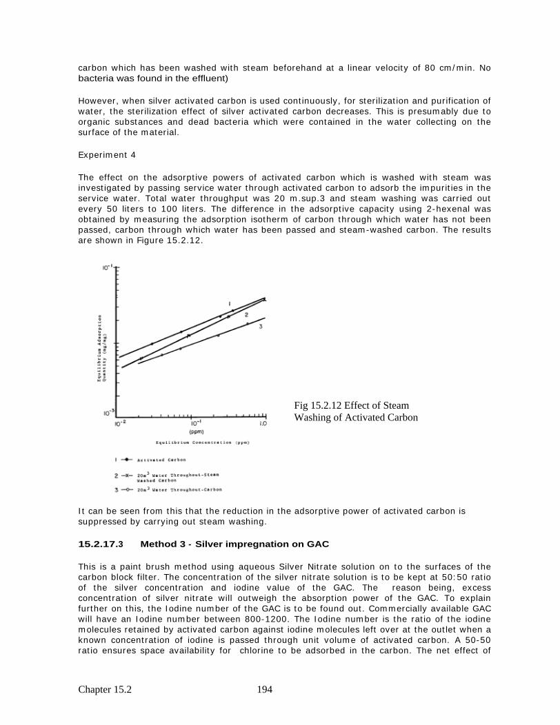
The effect on the adsorptive powers of activated carbon which is washed with steam was investigated by passing service water through activated carbon to adsorb the impurities in the service water. Total water throughput was 20 m.sup.3 and steam washing was carried out every 50 liters to 100 liters. The difference in the adsorptive capacity using 2-hexenal was obtained by measuring the adsorption isotherm of carbon through which water has not been passed, carbon through which water has been passed and steam-washed carbon. The results are shown in Figure 15.2.12.
It can be seen from this that the reduction in the adsorptive power of activated carbon is suppressed by carrying out steam washing.
15.2.17.3 Method 3 - Silver impregnation on GAC
This is a paint brush method using aqueous Silver Nitrate solution on to the surfaces of the carbon block filter. The concentration of the silver nitrate solution is to be kept at 50:50 ratio of the silver concentration and iodine value of the GAC. The reason being, excess concentration of silver nitrate will outweigh the absorption power of the GAC. To explain further on this, the Iodine number of the GAC is to be found out. Commercially available GAC will have an Iodine number between 800-1200. The Iodine number is the ratio of the iodine molecules retained by activated carbon against iodine molecules left over at the outlet when a known concentration of iodine is passed through unit volume of activated carbon. A 50-50 ratio ensures space availability for chlorine to be adsorbed in the carbon. The net effect of
Fig 15.2.12 Effect of Steam Washing of Activated Carbon

Chapter 15.2 195
bactericidal action is quite synergic. The combined Silver/Chlorine effect on bacteria is very faster and effective towards disinfection.
15.2.17.4 Method 4 - Silver impregnation on GAC
In this method, the GAC is mixed with an binding agent and extruded in cylindrical form. The binding agent is mixed with the salts of silver such as silver nitrate or silver chloride or silver sulphate. A silver containing plastic master batch is also acceptable as long as the binding material can hold its property at the melting temperature of plastic master batch. Another additive to the binding agent is by nano silver colloid with heating up to 200 deg C to impregnate on to binding material. Finally the whole combination needs to be extruded in cylindrical form.
Fig. 15.2.13 Impregnation of silver on GAC Fig. 15.2.14 Nano colloidal Silver in
precipitation (SizeX4)
Fig. 15.2.15 Nano colloidal Silver in precipitation
Figures above show the photographs done in Scanning Electro Microscope on the impregnation of silver on GAC

Chapter 15.3 196
CHAPTER 15.3
15.3 .0 Nano Silver impregnated fabric
2 Dia Thickness 2cm
10 High
Carbon block Nano Silver Fabric Retainer Nylon Net
Fig 15.3.1 Standard Dimensions for Fig 15.3.2 Coated Plain ceramic cartridge Inner Application of Nano Silver Side covered with a sediment filter Coated fabric base structure
Fabric Coated Nano Silver works as the best source of disinfection medium. The basis of making the fabric is to first make the yarn base. The yarn is coated with nano silver with suitable stabilizing agent so that the attached silver particles do not leach at the operating pressure of water. Yarn can be coated before or after spinning to a standard fabric cloth.
The application of the nano silver coated fabric to water disinfection is very easy. It is just to wrap around the carbon block filter and above the silver fabric, a retainer nylon mesh is wrapped around. This results in a firm structure for removal of bacteria and volatile organic matter along with dissolved chlorine in water. The figure 15.3.2 above shows the arrangement.
Once it is wrapped to the standard size of carbon block, the whole cartridge can be employed inside the standard 10 inch plastic bowl, as below:

Chapter 15.3 197
(Once through model) Fig 15.3.3 One to one contact method for Nano Silver and the microbe
15.3.2 Methods of Impregnation of nano Silver on Fabric
There are three methods with which we can impregnate nano silver on fabric.
a. Vacuum impregnation method b. Chemical silver plating method c. Electro spinning method.
15.3.2 .1 Method 1 : Vacuum Impregnation Method.
In this method, the spun cloth of fabric, either polyester or cotton fabric, will be allowed inside a vacuum chamber with pressure kept at 10-6 pa. An atomizer loaded with nano silver powder in ethanol solution is sprayed at a 100 deg Celsius temperature in to the chamber. In less than 20 seconds the nano silver particles attach to the surface of the fabric.
Amore effective method is to bring the polyester (not cotton fabric), close to melting point. At that temperature if the silver is impregnated to the fabric, the particles are attached to the surface of the fabric. The cloth is immediately cooled to hold the silver particles on the surface very firmly. The effective binding strength increases between the fabric and the silver particles, compared to low temperature adhesion process.
Ceramic Filter
Water Out Water in
Fig 15.3.4 Method of employing nano Silver cartridge for disinfection of Water Typical Method uses pre filtration stages for sediments and chlorine

Chapter 15.3 198
Fig 15.3.5 Fabric Spun with Nano Silver Fig 15.3.6 Vacuum impregnated Nano Silver impregnated Yarn. Spinning is done Cloth at spinning mill
Fig 15.3.7 (a) Magnified image of polymer grafted fabric (b) Silver deposits on to fiber strands (b) the final finish of a Silver Coated Fabric

Chapter 15.3 199
Nano Silver impregnated Fabric by Chemical Plating
15.3.2.2 Method 2 : Chemical method of Silver coating on Fabric
In order to localize the deposition of silver on a particular part of the surface of a piece of fabric, it is necessary to have the surface of the fabric act as a catalyst. The activation energy of the catalytic route is lower than the homogeneous reaction in a solution. A smooth deposition is obtained if the metal deposited by autocatalysis acts as a catalyst (Vaskelis 1999, Othmer 1995). Based on the method of chemical silver plating for non-metal substrates (Zeng 2002), the following three main steps were employed in the experiment:
pre-treatment,
plating process, and
post-treatment.
A general experimental plating steps in current design practice are summarized in Figure 1.
Fig. 15.3.8 Process steps in chemical silver coating (plating)
In order to test whether the silver particles had been well distributed on the surface of the fabric, all fabric samples had to undergo pre-treatment before chemical plating. They were subsequently rinsed with 5% detergent at room temperature for 20 minutes. All specimens had to have their surface act as a catalyst, i.e. sensitization. After ensitization, deionized water was used to clean the fabric samples before they underwent chemical plating. The application of the whole chemical solutions used for cleaning, sensitization and plating is shown in Table 15.3.1.
The pre-treated fabric samples were finally put in the chemical plating solution, which contained both Solution C and Solution D. In the experiment, the ratio of Solution C / Solution D is 1:3 in volume. After chemical silver plating, the samples had to be rinsed in deionized water immediately. Details of the experimental procedures are shown in Table 5.3.2.

Chapter 15.3 200
Table 15.3.1 Application of Chemical Solutions
Table 15.3.2 Chemical plating procedure
Procedure Solution Time (minute) Temperature
Pre-treatment 2000mL Solution A 20 Room temperature
Sensitization 1000mL Solution B 10 Room temperature
Plating 500mL Solution C & 1500mL Solution D
3 Room temperature
Post-treatment Rinse in flowing deionized water
20 Room temperature
15.3.2.3 Method 3 : Polymer fiber coated with Nano Silver Electro Spinning method
Titania with Silver To obtain a composite solution of titania and silver, silver nitrate is mixed with the initial precursor solution of Ti(OiPr)4, PVP, ethanol and acetic acid. The solution is made in batch by mixing 4.5 ml of Ti(OiPr)4 with 6ml ethanol and 6ml acetic acid. The solution is placed on a stir plate in a closed glass container for 1 hour. Concurrently a solution of 22.5ml ethanol and 1.35 grams PVP is mixed for an hour. Then 3.5ml of the Ti(OiPr)4 solution is mixed with 2.5ml of the PVP solution and kept in a closed container on the stir plate, which results in a solution of 0.165 g/cm 3 Ti(OiPr)4 and 0.025 g/cm 3 PVP.
After 45 minutes, 0.255 grams of AgNO3 is added and stirred until the solution looked homogenous (~30 minutes). This yields a solution with 42.5mg/cm 3 AgNO3 and 16.6 mg/cm 3 Ti(OiPr)4. This will result in nanofibers that contain 40% silver . The solution is then electrospun at a flow rate of 0.508ml/hour and at an electric field of 1.35kV/cm, where the voltage and distance are set to 6.78kV, and 5cm respectively.
ITEM SOLUTION CLEANING SOLUTION A
5% detergent with water; cleaning in double-deionized water before sensitization
Sensitization
Solution B 2-5g stannous chloride (SnCl2
.2H2O); 2-5mL hydrochloric acid (HCl, 37%); 1000 mL water
Plating Solution C Silver saline solution: 6g silver nitrate (AgNO3); 4g sodium hydrate (NaOH); a few drops of ammonium solution (NH4OH, 28%); 500mL water
Solution D Reduction solution: 1.3g glucose (C6H12O6); 500mL water

Chapter 15.3 201
Another solution may be established by adding 0.05 grams of silver nitrate to 6ml of a solution with the same ratio of constituents. This produces a concentration of 8.33mg/cm 3 of AgNO3. This will result in nano fibers with approximately 8% silver, with a view to test the effectiveness of varying the silver concentration on the photo catalytic activity of the fibers.
Fig 15.3.9 Nano Silver impregnation by Electro Spinning method. SEM photos of The fiber strands
Control of concentration of silver For the experiment of electric field the point to plate distance is kept at 3cm. The electric field may be varied over a range of 1kV/cm to 4kV/cm. Stable electrospinning occurs at these fields, however when the point to plate distance is changed to 5cm, stable electrospinning will occur at an electric field of 1-2kV/cm.
15.3 .3 Devices that can be used to fix the Nano Silver Fabric Cartridge for water purification
Fig 15.3.10 Single Stage Filter unit Fig 15.3.11 Multistage filter or With Domestic RO water Purifier combination

Chapter 15.4 202
Ceramic or activated Carbon filter layer
Silver polymer Filter
CHAPTER 15.4
15.4.1 Silver impregnated Fiber cartridge
Manufacturing the filter requires simple, locally-available materials and methods. The filter is 5 cm in diameter, 25cm high polyurethane filter, commercially available at a cost of $1 per cartridge. The method of silver coating has been followed as per (Kamat et al., 1998).
AgNO3 and trisodium citrate are used as major chemicals for coating the Polyurethane filter with nano silver. The cartridges is washed. Use of triple distilled water is essential for the synthesis and measurements. The synthesis of Ag@citrate is to be carried out according to the literature procedure (Kamat et al., 1998). Briefly, the synthesis involves the following materials and methods: 25 mL of 0.005 M stock solution of silver nitrate in water is diluted to 125 mL and heated until it begins to boil. Further 5 mL of 1% sodium citrate solution is added; heating continued until the color is pale yellow. The solution is cooled to room temperature.
The synthesized nanoparticles are characterized by ultraviolet (UV)-visible spectroscopy, transmission electron microscopy (TEM), and infrared (IR) spectroscopy (FTIR) for further analysis. The polyurethane filter element is to be choked in the liquid containing synthesized nano silver, over night for getting uniform coating of nano silver all around. The free nitrogen in the polyurethane structure gets exchanged with silver ions and the covalent bond is formed between the polymer and the silver ion. Thus resulting a pale golden color coating on the surface of the polyurethane filter.
15.4.2 The polymer media coated with Nano Silver
The possibilities of various models and platforms using the polymer PU filter is discussed below, pictorially. An industrial standard 2 Dia PU cartridge is the economical solution for the present application.
However the Silver polymer filter could be either covered by an activated carbon or ceramic filter envelop to increase the effective use of the multi layer filter for other removable impurities too.
15.4.3 Nano Silver impregnated Fiber cartridge
Fig 15.4.1 Nano Silver Coated Plain Fig 15.4.2 Coated Plain ceramic cartridge Inner Polyurethane cartridge Side covered with a nano silver coated
polyurethane filter
2 Dia
10 High Thickness 2cm

Chapter 15.4 203
Though a mushroom headed filter is possible in PU polymer, it is not an economical option compared to PU extrusion. The PU extrusion process is continuous and the required lengths could be cut as needed, which is the primary reason for ruling out the mushroom head Polymer commercially.
Silver Polymer Silver Polymer Single cartridge Double cartridge
Carbon Filter
Fig 15.4.3 One to one contact method for Fig 15.4.4 Water Dispensing Pot. Typical Nano Silver and the microbe Method of increasing contact time (Once through model) or flow, by single and double cartridges
by supernatant water column
15.4.4 Hydraulic design
The primary concern on the design is the sufficient flow to make the microbe contact with Nano Silver ions, with required contact time. Accordingly the bowl has the capacity of 1.96 liters. The flow of the liquid is controlled to fill 500 ml per minute will have a retention time of 4 minutes approximately. Hence the CT (contact time) of 4 minutes versus the concentration of Nano Silver ions will make the disinfection a viable one using the ceramic filters.
a. Inner Side Silver coated Polymer filter
2 Dia
10 High Thickness 2cm
Fig 15.4.5 Plain ceramic cartridge Inner Side covered with a silver coated polymer filter
Silver PU Filter
Water in
Water Out

Chapter 15.4 204
This design retains the same method as outlined in (a) above. Additionally, a 2 Dia polypropylene sediment filter is used to filter out the suspended particles of pore sizes lesser than those in the ceramic filter.
The significance of addition a polypropylene filter stage after the ceramic filter could be seen in two ways.
i. Adds certain degree of sediment filtration effect to suspended solids.
ii. The contact time of bacterial exposure can be increased significantly by
introducing nano silver coated polypropylene filter.
iii. Either the ceramic or the polypropylene filter can be silver coated or both
can be coated to increase the concentration of silver ions to be populated in
water.
iv. This model can accept an external pressure through a pump if the final
product water quantity is needed in excess quantity.
The hydraulic design can be worked out to meet both the contact time required and or the final flow required.
b. Test Setup for Silver ion Leach study.
Fig 15.4.6 Design of the Filter apparatus for the Study of silver ion leaching
The apparatus above is used for the study of leaching of silver from Nano Silver impregnated Fiber. . The results are provided in later chapters. The apparatus essentially has a water tank for circulation. A diaphragm pump is used to continuously pump the water inside the filter. Water undergoes an activated carbon filtration first and then a sediment filtration. The Nano Silver

Chapter 15.4 205
Silver impregnated Fiber is kept as the last stage. Pressure can be increased by adjusting the valves provided at entry point. Thereby the flow increases. Final stage of the filter is provided with a flow restrictor which allows only 500 ml of water per minute. This set up simulates an ideal condition of application at field. The flow restrictor can be changed to 300 ml, 400 ml 750ml etc. Depending on the requirement the units can be retrofitted at field.
Tests were carried out for a continuous period of 12 weeks and samples were taken at required intervals. The samples were analyzed for leached silver using the standard titration methods as per international standards of testing at the laboratory. The results are tabulated in the results and discussion session.
15.4.5 APPLICATIONS
Silver impregnated Fiber filter provides a critical service to areas where water quality is poor and where the water supply infrastructure is lacking. Ideally, the filter should not be used for long-term water purification in urban areas. Currently, the best possible drinking water quality is achieved from well-run water treatment plants with piped service to households. The Silver impregnated Fiber filter is a viable interim solution for disaster relief in urban areas until the water supply is returned. For areas without any foreseeable access to piped drinking water supplies, the Silver impregnated Fiber filter offers a cheap and effective intermediate water purification technology. Filters should be regularly inspected for cracks and replaced every one to two years to avoid loss of biocidal action. The lifetime of the filter may be extended by intermittently back washing from the inside of the filter and pre-filtering the raw water with a cloth. When combined with training for the users, the Silver impregnated Fiber filter is an effective and appropriate technology that improves both water quality and human health.

Chapter 15.5 206
CHAPTER 15.5
15.5.1 Nano Silver impregnated polymer
The basic principle of application of this method is to have a geometrically designed polymer, which is mixed with Nano Silver particles, done on injection molding process.
Figure 15.5.1 : Nano Silver mixed injection molding Disinfection chamber for water filter
Figure 15.5.2 : Nano Silver disinfection Figure 15.5.3 : Nano Silver disinfection Water Purifier components split view Water Purifier Assembly view
The basic method of mixing the nano silver into the plastic is by using a master batch mix. There are many industries selling master batch compounds, meant for addition of specific pigments to plastic base to obtain a specific variety of plastic. The master batch is essentially a concentrated

Chapter 15.5 207
mixture of the basic pigment (in our case it is nano silver powder) with low density Polypropylene pebbles. The mixture is packed and provided as 50 % or 100% concentration of Silver.
The master batch is mixed with the ratio needed in the raw plastic prior to injection molding. The raw materials are thoroughly mixed in a mixer and pre heated to master batch melting temperature. The master batch which has lower melting point will be liquefied first. The liquid master batch fixes on to the plastic raw material and once taken out it forms a uniform mixing of plastic granules already mixed with required concentration of Nano Silver.
15.5.2 The design for microbial contact:
The disinfection rate of this equipment largely depends on the one to one contact between the nano silver ion and the microbe. The arrangement above shows the nano silver water purifier, some what looking like a traditional water filter kept at homes in India.
The upper portion of the filter consists of a water filling chamber along with a basic sediment filter and a combination GAC filter. They are in the form of a cartridge and they are secured to the bottom of the top chamber.
The bottom chamber has a dispenser pipe. The Nano Silver Polymer is just kept inside the chamber. The filtered water from the top chamber by gravity, will need to pass through many turns of the Nano Silver Polymer. Before it reaches the faucet it makes several contacts with the bends and curves of the Nano Silver Polymer, thereby making a one to one contact between Nano silver particles in the polymer and microbe. At the point of exit, the water is purified.
Instead of Nano Silver Master Batch mixing, the whole disinfection polymer can be made out of polyurethane and then the surface can be coated with nano silver by simple method explained in earlier chapter for polyurethane fiber coating process. Care should be taken to ensure that this method may have more leached silver as the silver holding mechanism is a surface phenomenon (or by London Forces).
15.5.3 Hydraulic design:
The design of this water filter is based on the volume capacity needed per family per day. Accordingly, a 2 gallon (8 liter ) water tank on upper and a 9 liter water tank on the lower is designed to meet the needs of pure drinking water per family. The filtered water flow is restricted by the pressure drop offered by the filtering units. Careful design can alleviate many hydraulic constraints.
The cost of this equipment is roughly Rs 800/- (US $16) for a mass production.

Chapter 15.5 208
The details of commercially available Master Batch Nano Silver are provided below;
Mono nano silver antimicrobial plastic master batch
Code: PP, PE, ABS, PET3000, AGS-DMB5000
Major ingradient: mono nano silver
Content: PP, PE, ABS, PET3000 (3000ppm), AGS-DMB5000(5000ppm)
Particle diameter: 20nm
Color: tawny
Characteristics:
1. Broad-spectrum sterilization: can kill over 99% of colon bacteria, staphylococcus aureus,
streptococcus albus and molds etc. rapidly.
2. Long-lasting effect: The antimicrobial validity is same with the finished goods . 3. Appearance: uniform size, good plastification, unanimous color, no obvious impurities. 4. Economy: highly efficient, small adding can have an obvious effect. 5. Good heat stability: endure high temperature and not easy to change color. 6. Good
compatibility and dispersibility.
7. Do not change the plastic s original processing techniques and the plastic s original functions.
8. Safty and nontoxic,do not pollute the environment.
9. Non-toxicity: Active ingredient has been tested by authorized departments such as SGS and
Centers for Disease Control.
10. Dispersibility and uniformity:the surface of the product which add antimicrobial masterbatch
do not have the megascopic solid particles.
Application range:
The mono nano silver antimicrobial plastic masterbatch can be added in various plastic and fiber
products such as ABS,PC,PET,PE,PP etc.The specific ranges are :
1. Home Appliances: refrigerator, washing machine,rice cooker, television, camera, etc.
2.Chemical building materials:plastic pipe, toilet facilities, tub, sitting w.c.pan, public
accommodation, plastic floor etc.
3. Electronic products: telephone, electrograph, phone, computer, mouse etc.
4. Medical and health products: hospital facilities, medical instruments, one-off gloves, etc.
5. Daily necessities: shaver, calculator, toy, stationery, furniture, bucket and cup, etc.
6. Automotive industry: door handle, dash board, steering wheel and jockey box, etc.

Chapter 15.5 209
7. Package industry: drink bottle, water bucket, and package film, etc.
Usage:
Plus this product into common plastic masterbatch and mixed up as 5% proportation.
Silver zirconium phosphate antimicrobial plastic masterbatch
Code:AGS-ZMB6000 Major ingredient: zirconium phosphate, silver ion compound. Content:6000ppm Particle diameter: 200nm Color:White Characteristic:
This inorganic antimicrobial master batch use the silver ion as the major bactericidal ingredients
and use the zirconium phosphate to be the carrier of silver ion.This master batch can endure the
high temperature,do not change the color,mix with PP/PET/PE/ABS/EVA etc to produce several
antimicrobial products. It is broad-spectrum bactericidal, lasting anti-bacterial.
Application range:
The silver zirconium phosphate antimicrobial plastic masterbatch can be added in various plastic
and fiber products such as PP/PET/PE/ABS/EVA etc.The specific ranges are :Food packaging,
medical equipment, all kinds of antimicrobial fibre,
antimicrobial fresh-keeping film etc.
Usage:
Plus this product into common plastic masterbatch and mixed up as 5% proportation.
Inorganic nano silver antimicrobial powder
Code: AGP-ZP003
Major ingredient: nano silver
The content of silver: 3.0%

Chapter 15.5 210
Particle diameter: <1um
Color: white
Tap density:1.8g/ml
The content of water: 0.6%
PH value:5.5
Igloss decrement: 1.0%
Temperature resistance:>280
Whiteness: 96
Characteristic:
The Inorganic nano silver antimicrobial powder can be added into several products.The final
product have a broad-spectrum sterilization,can endure high temperature,not easy to change
color, safty, nontoxic and long-lasting effect.It can use for PP/PET/PE/ABS/EVA etc.
Application range:
Widely use for PP/PET/PE/ABS/EVA and other basic plastic material.It can produce film and
superfine fibre etc.
Usage:
Plus this product into the final product and mix up as 1% proportation.