Chapter 12: Structures & Properties of...
36
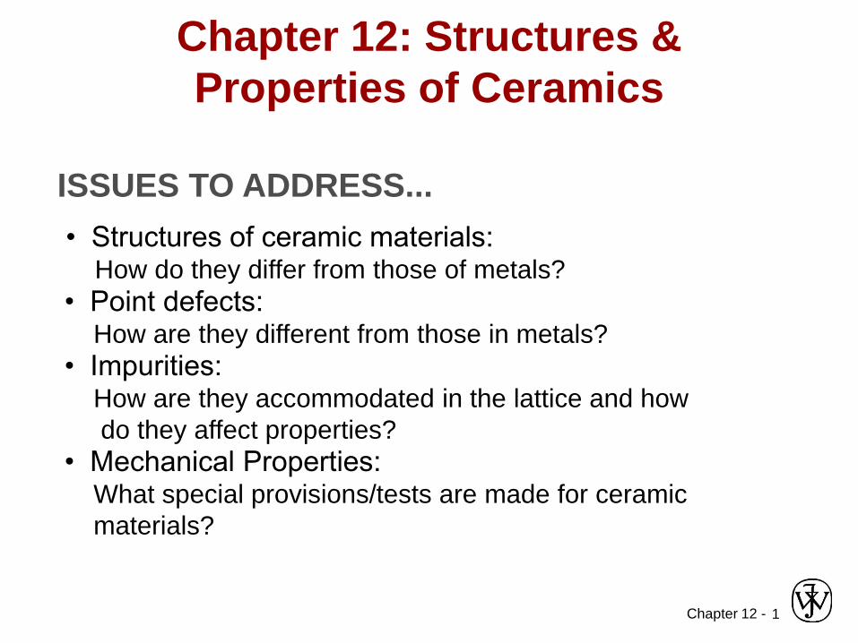
Chapter 12 - 1 ISSUES TO ADDRESS... • Structures of ceramic materials: How do they differ from those of metals? • Point defects: How are they different from those in metals? • Impurities: How are they accommodated in the lattice and how do they affect properties? • Mechanical Properties: What special provisions/tests are made for ceramic materials? Chapter 12: Structures & Properties of Ceramics
Transcript of Chapter 12: Structures & Properties of...
Chapter 12 - 1
ISSUES TO ADDRESS...
• Structures of ceramic materials:How do they differ from those of metals?
• Point defects:How are they different from those in metals?
• Impurities:How are they accommodated in the lattice and how
do they affect properties?
• Mechanical Properties:What special provisions/tests are made for ceramic
materials?
Chapter 12: Structures &
Properties of Ceramics
Chapter 12 - 2
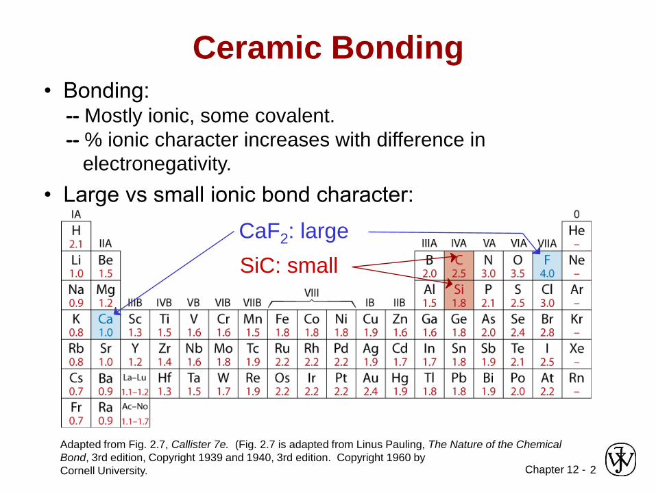
• Bonding:-- Mostly ionic, some covalent.
-- % ionic character increases with difference in
electronegativity.
Adapted from Fig. 2.7, Callister 7e. (Fig. 2.7 is adapted from Linus Pauling, The Nature of the Chemical
Bond, 3rd edition, Copyright 1939 and 1940, 3rd edition. Copyright 1960 by
Cornell University.
• Large vs small ionic bond character:
Ceramic Bonding
SiC: small
CaF2: large
Chapter 12 - 3
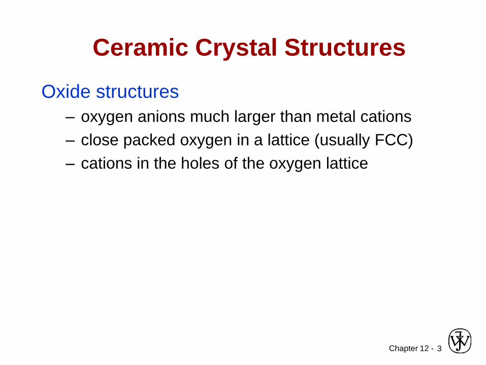
Ceramic Crystal Structures
Oxide structures
– oxygen anions much larger than metal cations
– close packed oxygen in a lattice (usually FCC)
– cations in the holes of the oxygen lattice
Chapter 12 - 4
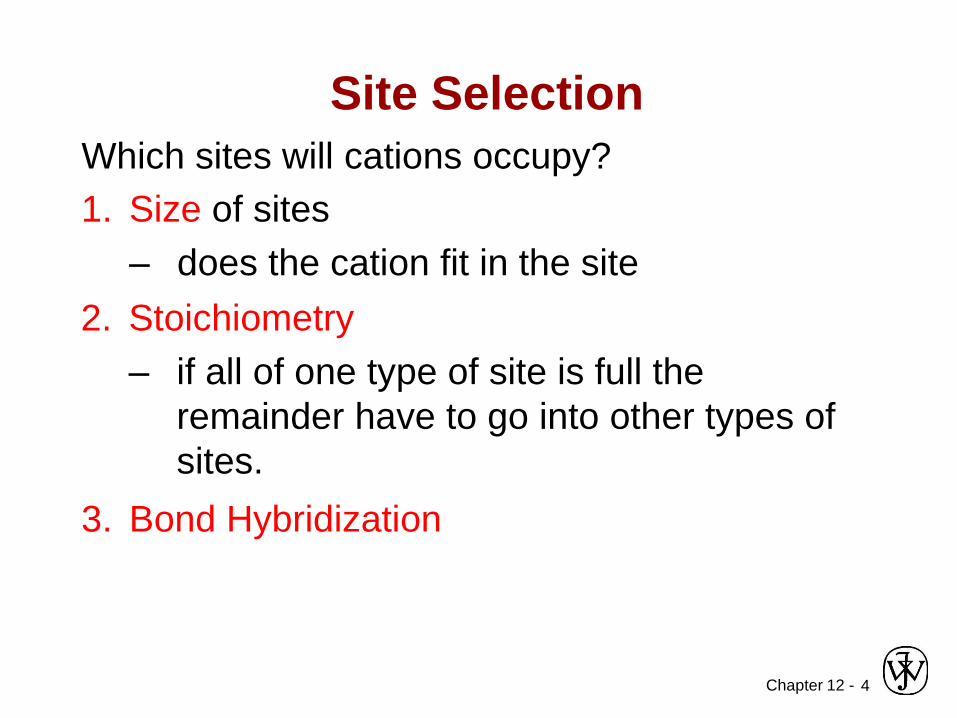
Which sites will cations occupy?
Site Selection
1. Size of sites
– does the cation fit in the site
2. Stoichiometry
– if all of one type of site is full the
remainder have to go into other types of
sites.
3. Bond Hybridization
Chapter 12 - 5
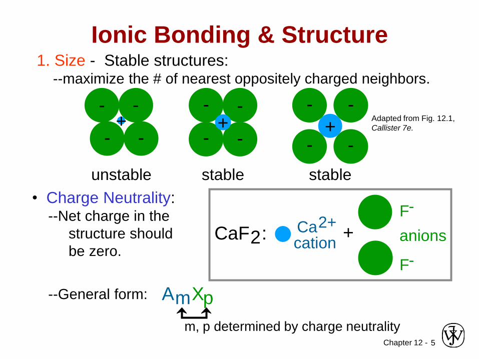
Ionic Bonding & Structure1. Size - Stable structures:
--maximize the # of nearest oppositely charged neighbors.
Adapted from Fig. 12.1,
Callister 7e.
- -
- -+
unstable
• Charge Neutrality:--Net charge in the
structure should
be zero.
--General form:
- -
- -+
stable
- -
- -+
stable
CaF2: Ca2+
cation
F-
F-
anions+
AmXp
m, p determined by charge neutrality

Chapter 12 - 6
• Coordination # increases with
Coordination # and Ionic Radii
Adapted from Table 12.2,
Callister 7e.
2
rcationranion
Coord
#
< 0.155
0.155 - 0.225
0.225 - 0.414
0.414 - 0.732
0.732 - 1.0
3
4
6
8
linear
triangular
TD
OH
cubic
Adapted from Fig.
12.2, Callister 7e.
Adapted from Fig.
12.3, Callister 7e.
Adapted from Fig.
12.4, Callister 7e.
ZnS (zincblende)
NaCl(sodium
chloride)
CsCl(cesium chloride)
rcationranion
Issue: How many anions can you
arrange around a cation?
Chapter 12 - 7
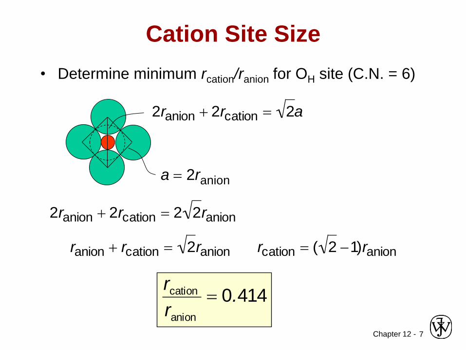
Cation Site Size
• Determine minimum rcation/ranion for OH site (C.N. = 6)
a = 2ranion
2ranion 2rcation = 2 2ranion
ranion rcation = 2ranion
rcation = ( 2 1)ranion
2ranion 2rcation = 2a
4140anion
cation .r
r=
Chapter 12 - 8
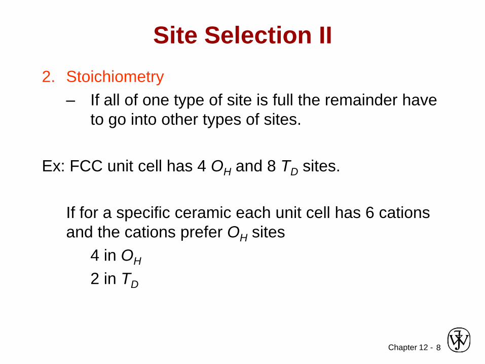
Site Selection II
2. Stoichiometry
– If all of one type of site is full the remainder have
to go into other types of sites.
Ex: FCC unit cell has 4 OH and 8 TD sites.
If for a specific ceramic each unit cell has 6 cations
and the cations prefer OH sites
4 in OH
2 in TD
Chapter 12 - 9
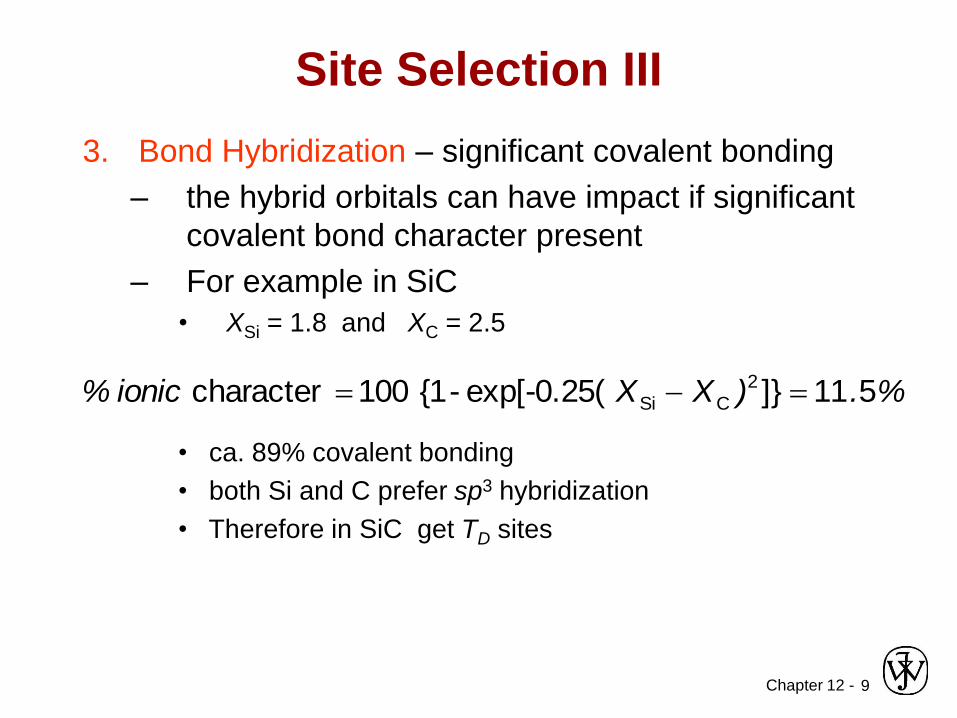
Site Selection III
3. Bond Hybridization – significant covalent bonding
– the hybrid orbitals can have impact if significant
covalent bond character present
– For example in SiC
• XSi = 1.8 and XC = 2.5
%.)XXionic% 511]}exp[-0.25(-{1 100 character 2
CSi ==
• ca. 89% covalent bonding
• both Si and C prefer sp3 hybridization
• Therefore in SiC get TD sites
Chapter 12 -10
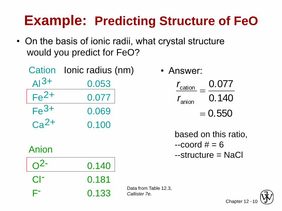
• On the basis of ionic radii, what crystal structure
would you predict for FeO?
• Answer:
5500
1400
0770
anion
cation
.
.
.
r
r
=
=
based on this ratio,
--coord # = 6
--structure = NaCl
Data from Table 12.3,
Callister 7e.
Example: Predicting Structure of FeO
Ionic radius (nm)
0.053
0.077
0.069
0.100
0.140
0.181
0.133
Cation
Anion
Al3+
Fe2+
Fe3+
Ca2+
O2-
Cl-
F-
Chapter 12 - 11
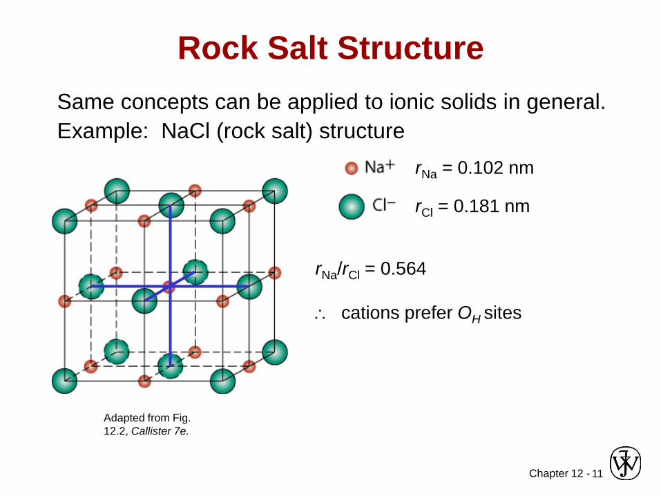
Rock Salt Structure
Same concepts can be applied to ionic solids in general.
Example: NaCl (rock salt) structure
rNa = 0.102 nm
rNa/rCl = 0.564
cations prefer OH sites
Adapted from Fig.
12.2, Callister 7e.
rCl = 0.181 nm
Chapter 12 -12
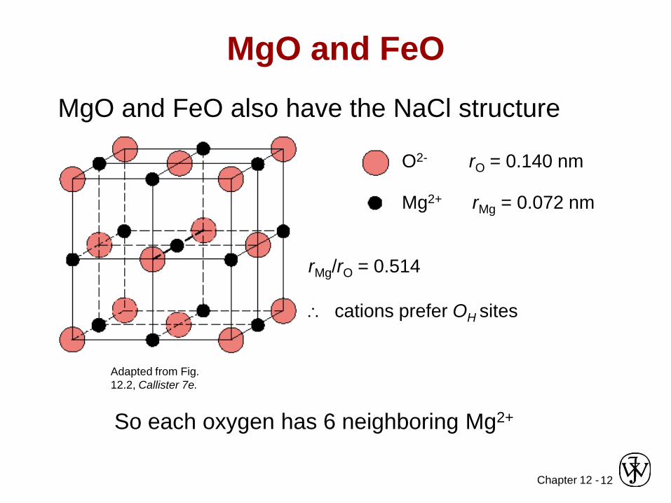
MgO and FeO
MgO and FeO also have the NaCl structure
O2- rO = 0.140 nm
Mg2+ rMg = 0.072 nm
rMg/rO = 0.514
cations prefer OH sites
So each oxygen has 6 neighboring Mg2+
Adapted from Fig.
12.2, Callister 7e.
Chapter 12 -13
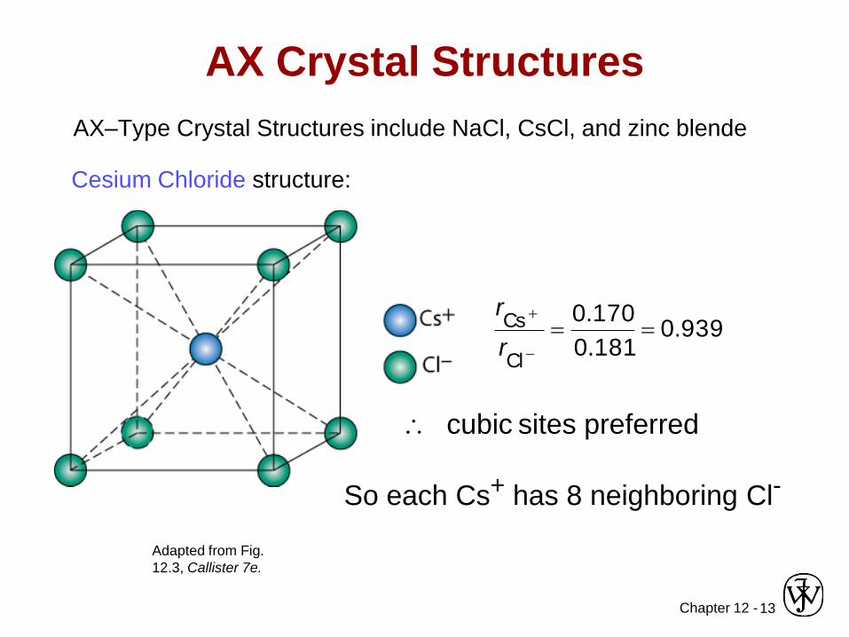
AX Crystal Structures
AX–Type Crystal Structures include NaCl, CsCl, and zinc blende
939.0181.0
170.0
Cl
Cs ==
r
r
Adapted from Fig.
12.3, Callister 7e.
Cesium Chloride structure:
cubic sites preferred
So each Cs+ has 8 neighboring Cl-
Chapter 12 -14
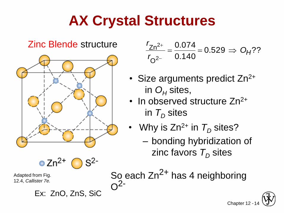
AX Crystal Structures
So each Zn2+ has 4 neighboring
O2-
Zinc Blende structure
Adapted from Fig.
12.4, Callister 7e.
?? 529.0140.0
074.0
2
2
O
ZnHO
r
r==
• Size arguments predict Zn2+
in OH sites,
• In observed structure Zn2+
in TD sites
• Why is Zn2+ in TD sites?
– bonding hybridization of
zinc favors TD sites
Ex: ZnO, ZnS, SiC
Chapter 12 -15
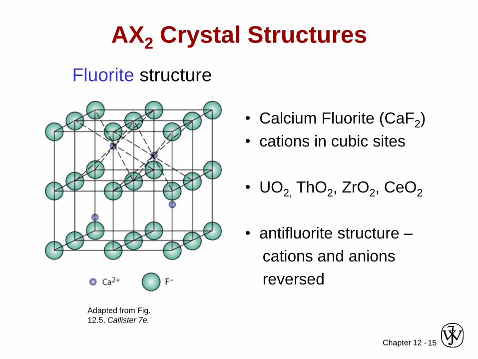
AX2 Crystal Structures
Fluorite structure
• Calcium Fluorite (CaF2)
• cations in cubic sites
• UO2, ThO2, ZrO2, CeO2
• antifluorite structure –
cations and anions
reversed
Adapted from Fig.
12.5, Callister 7e.
Chapter 12 -16
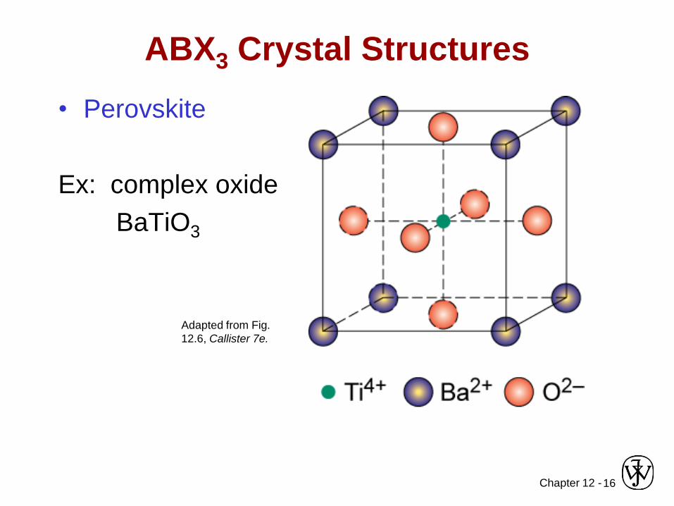
ABX3 Crystal Structures
• Perovskite
Ex: complex oxide
BaTiO3
Adapted from Fig.
12.6, Callister 7e.
Chapter 12 -17
Mechanical Properties
We know that ceramics are more brittle than
metals. Why?
• Consider method of deformation
– slippage along slip planes
• in ionic solids this slippage is very difficult
• too much energy needed to move one anion past
another anion
Chapter 12 -18
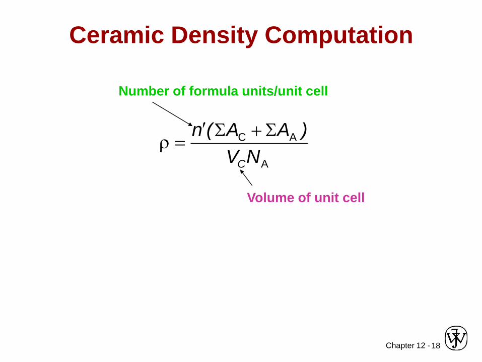
Ceramic Density Computation
A
AC
NV
)AA(n
C
=
Number of formula units/unit cell
Volume of unit cell
Chapter 12 -19
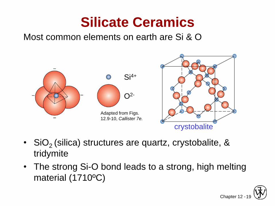
Silicate CeramicsMost common elements on earth are Si & O
• SiO2 (silica) structures are quartz, crystobalite, &
tridymite
• The strong Si-O bond leads to a strong, high melting
material (1710ºC)
Si4+
O2-
Adapted from Figs.
12.9-10, Callister 7e.
crystobalite
Chapter 12 -20
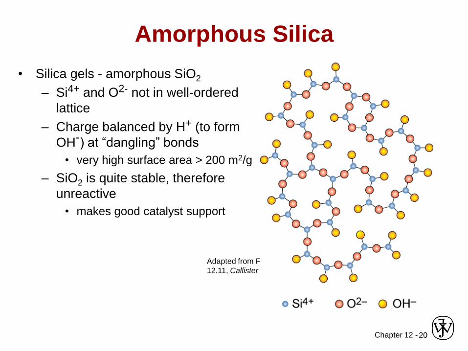
Amorphous Silica
• Silica gels - amorphous SiO2
– Si4+ and O2- not in well-ordered
lattice
– Charge balanced by H+ (to form
OH-) at “dangling” bonds
• very high surface area > 200 m2/g
– SiO2 is quite stable, therefore
unreactive
• makes good catalyst support
Adapted from Fig.
12.11, Callister 7e.
Chapter 12 -21
Silica Glass
• Dense form of amorphous silica
– Charge imbalance corrected with “counter
cations” such as Na+
– Borosilicate glass is the pyrex glass used
in labs• better temperature stability & less brittle than sodium
glass
Chapter 12 -22
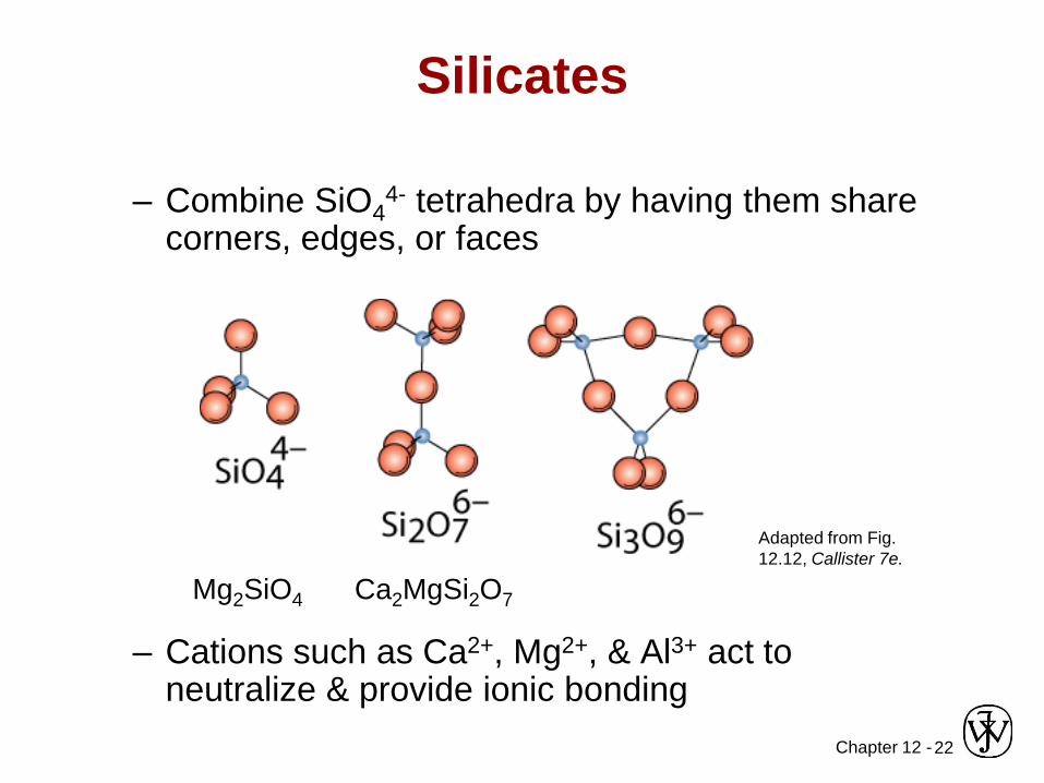
– Combine SiO44- tetrahedra by having them share
corners, edges, or faces
– Cations such as Ca2+, Mg2+, & Al3+ act to neutralize & provide ionic bonding
Silicates
Mg2SiO4 Ca2MgSi2O7
Adapted from Fig.
12.12, Callister 7e.
Chapter 12 -23
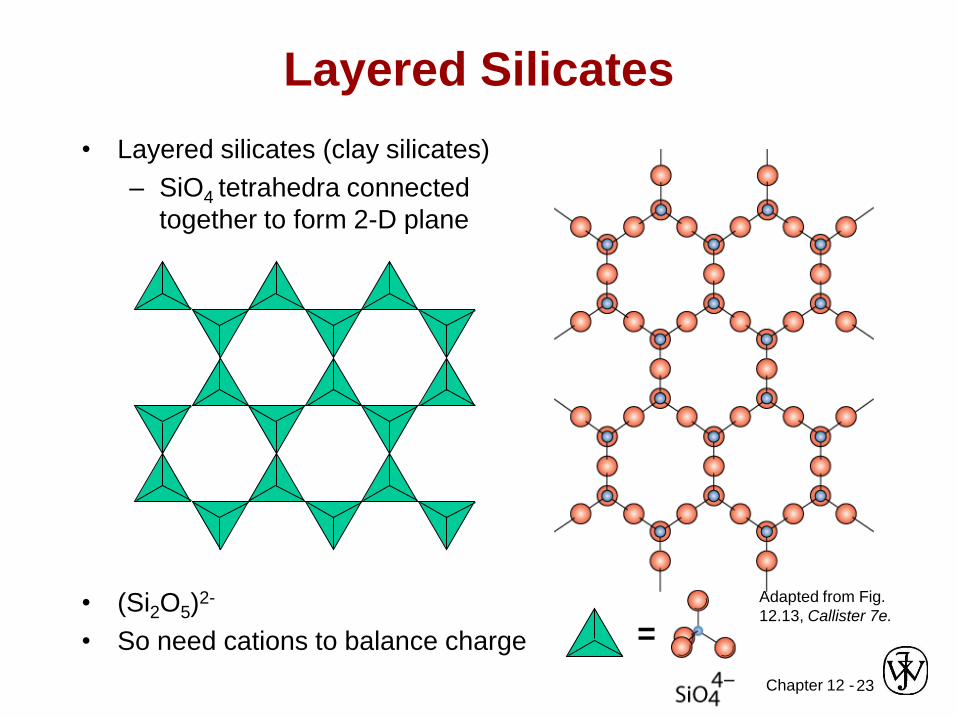
Layered Silicates
• Layered silicates (clay silicates)
– SiO4 tetrahedra connected
together to form 2-D plane
• (Si2O5)2-
• So need cations to balance charge =
Adapted from Fig.
12.13, Callister 7e.
Chapter 12 -24
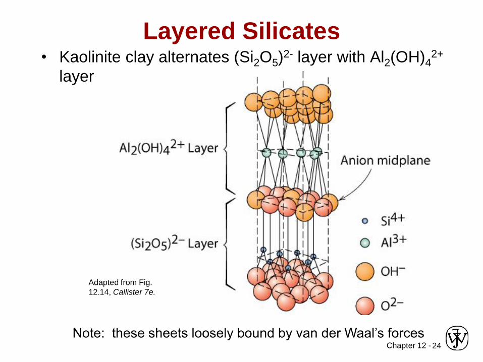
• Kaolinite clay alternates (Si2O5)2- layer with Al2(OH)4
2+
layer
Layered Silicates
Note: these sheets loosely bound by van der Waal’s forces
Adapted from Fig.
12.14, Callister 7e.
Chapter 12 -25
Layered Silicates
• Can change the counterions
– this changes layer spacing
– the layers also allow absorption of water
• Micas KAl3Si3O10(OH)2
• Bentonite
– used to seal wells
– packaged dry
– swells 2-3 fold in H2O
– pump in to seal up well so no polluted ground
water seeps in to contaminate the water supply.
Chapter 12 -26
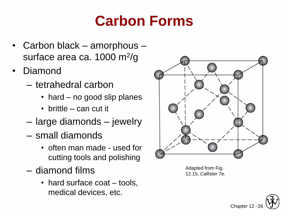
Carbon Forms
• Carbon black – amorphous –
surface area ca. 1000 m2/g
• Diamond
– tetrahedral carbon
• hard – no good slip planes
• brittle – can cut it
– large diamonds – jewelry
– small diamonds
• often man made - used for
cutting tools and polishing
– diamond films
• hard surface coat – tools,
medical devices, etc.
Adapted from Fig.
12.15, Callister 7e.
Chapter 12 -27
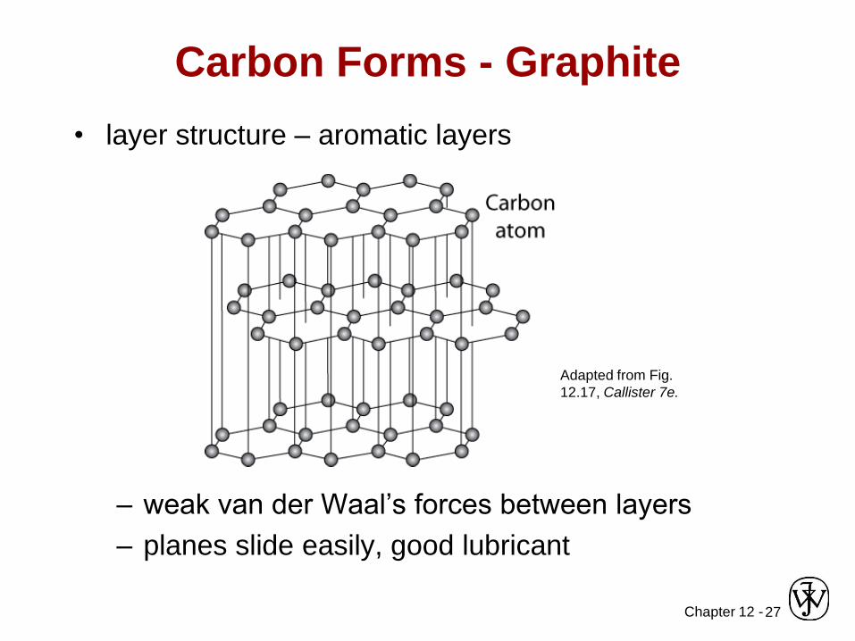
Carbon Forms - Graphite
• layer structure – aromatic layers
– weak van der Waal’s forces between layers
– planes slide easily, good lubricant
Adapted from Fig.
12.17, Callister 7e.
Chapter 12 -28
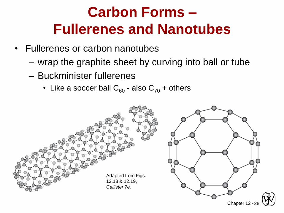
Carbon Forms –
Fullerenes and Nanotubes
• Fullerenes or carbon nanotubes
– wrap the graphite sheet by curving into ball or tube
– Buckminister fullerenes
• Like a soccer ball C60 - also C70 + others
Adapted from Figs.
12.18 & 12.19,
Callister 7e.
Chapter 12 -29
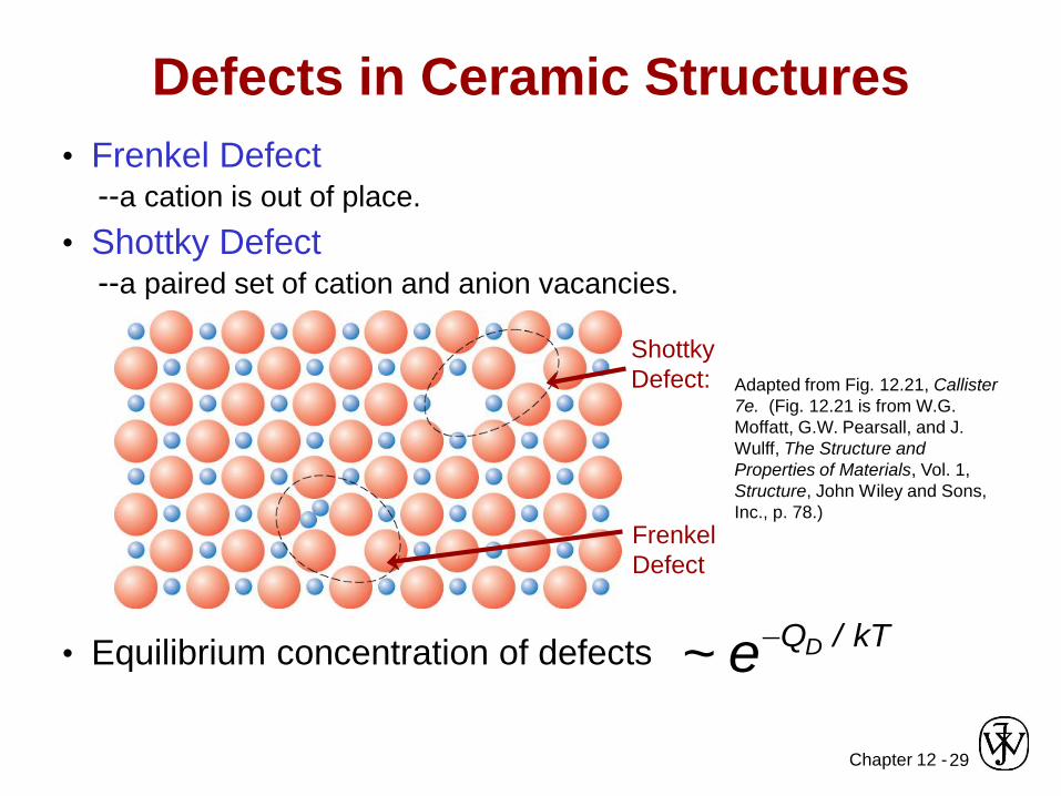
• Frenkel Defect--a cation is out of place.
• Shottky Defect--a paired set of cation and anion vacancies.
• Equilibrium concentration of defects kT/QDe~
Adapted from Fig. 12.21, Callister
7e. (Fig. 12.21 is from W.G.
Moffatt, G.W. Pearsall, and J.
Wulff, The Structure and
Properties of Materials, Vol. 1,
Structure, John Wiley and Sons,
Inc., p. 78.)
Defects in Ceramic Structures
Shottky
Defect:
Frenkel
Defect
Chapter 12 -30
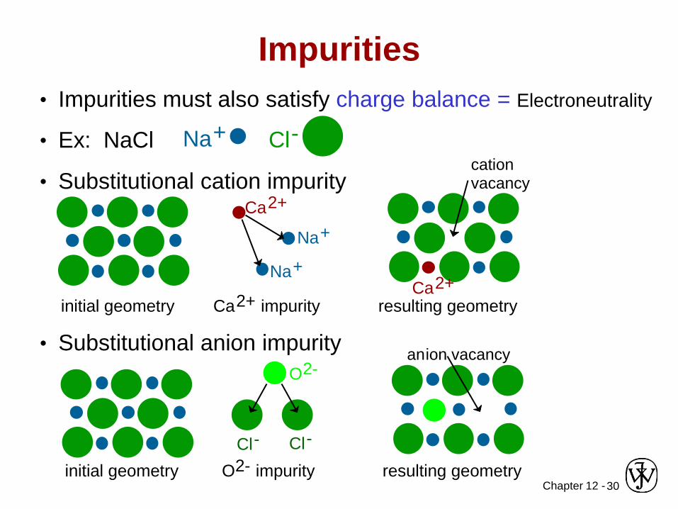
• Impurities must also satisfy charge balance = Electroneutrality
• Ex: NaCl
• Substitutional cation impurity
Impurities
Na+ Cl-
initial geometry Ca2+ impurity resulting geometry
Ca2+
Na+
Na+
Ca2+
cation vacancy
• Substitutional anion impurity
initial geometry O2- impurity
O2-
Cl-
anion vacancy
Cl-
resulting geometry
Chapter 12 -31
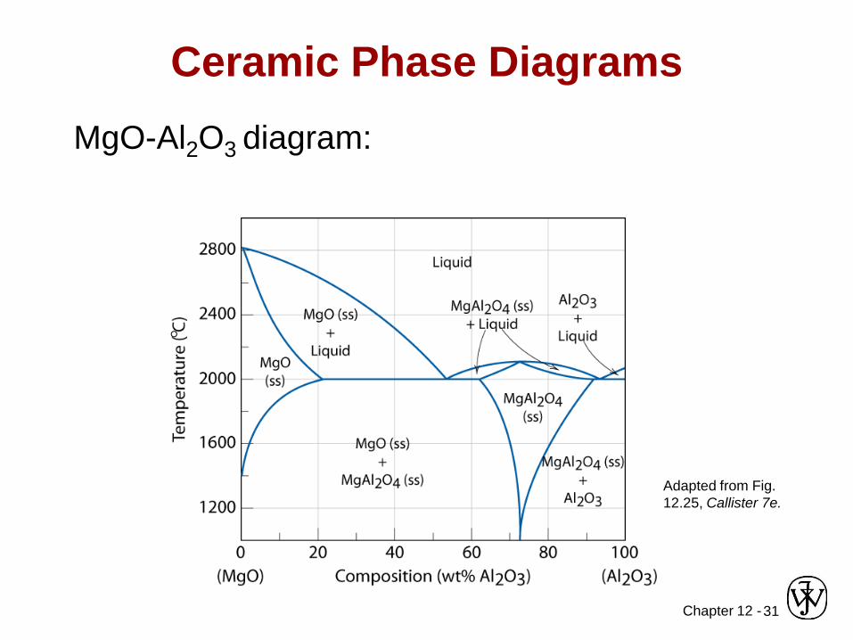
Ceramic Phase Diagrams
MgO-Al2O3 diagram:
Adapted from Fig.
12.25, Callister 7e.
Chapter 12 -32
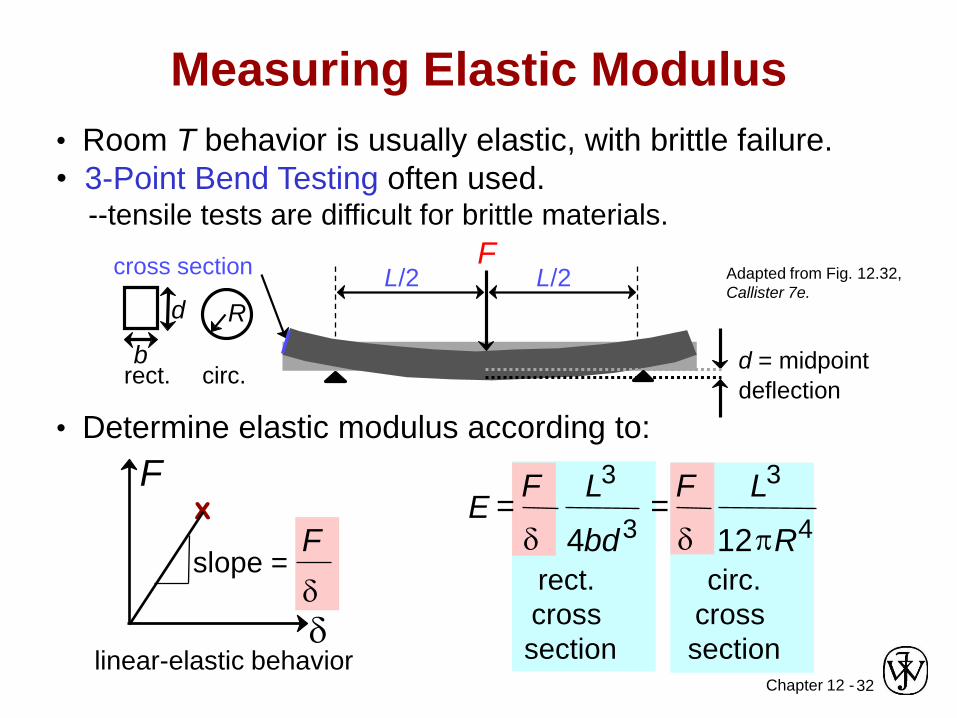
• Room T behavior is usually elastic, with brittle failure.
• 3-Point Bend Testing often used.--tensile tests are difficult for brittle materials.
Adapted from Fig. 12.32,
Callister 7e.
Measuring Elastic Modulus
FL/2 L/2
d = midpoint
deflection
cross section
R
b
d
rect. circ.
• Determine elastic modulus according to:
Fx
linear-elastic behaviord
F
dslope =
E =F
d
L3
4bd3=
F
d
L3
12pR4
rect.
cross
section
circ.
cross
section
Chapter 12 -33
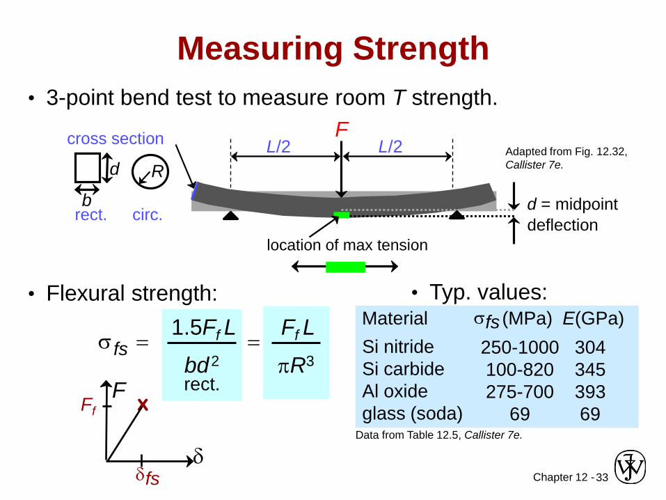
• 3-point bend test to measure room T strength.
Adapted from Fig. 12.32,
Callister 7e.
Measuring Strength
FL/2 L/2
d = midpoint
deflection
cross section
R
b
d
rect. circ.
location of max tension
• Flexural strength: • Typ. values:
Data from Table 12.5, Callister 7e.
rect.
sfs =1.5Ff L
bd2
=Ff L
pR3Si nitride
Si carbide
Al oxide
glass (soda)
250-1000
100-820
275-700
69
304
345
393
69
Material sfs (MPa) E(GPa)
xF
Ff
dfsd
Chapter 12 -34
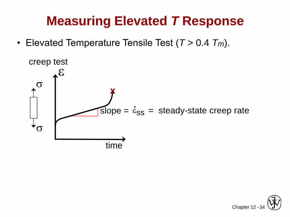
Measuring Elevated T Response
e
time
• Elevated Temperature Tensile Test (T > 0.4 Tm).
creep test
s
s
slope = ess = steady-state creep rate.
x
Chapter 12 -35
• Ceramic materials have covalent & ionic bonding.
• Structures are based on:-- charge neutrality
-- maximizing # of nearest oppositely charged neighbors.
• Structures may be predicted based on:
-- ratio of the cation and anion radii.
• Defects
-- must preserve charge neutrality
-- have a concentration that varies exponentially w/T.
• Room T mechanical response is elastic, but fracture
is brittle, with negligible deformation.
• Elevated T creep properties are generally superior to
those of metals (and polymers).
Summary
Chapter 12 -36
Core Problems:
Self-help Problems:
ANNOUNCEMENTS
Reading: