Chapter 12: Facilities System Safety · PDF fileChapter 12: Facilities System Safety ... 13...
38
FAA System Safety Handbook, Chapter 12: Facilities Safety December 30, 2000 Chapter 12: Facilities System Safety 12.1 INTRODUCTION ....................................................................................................................... 2 12.2 NEW FACILITY SYSTEM SAFETY ....................................................................................... 4 12.3 EXISTING FACILITIES ........................................................................................................... 7 12.4 FACILITY SYSTEM SAFETY PROGRAM.......................................................................... 9 12.5 ANALYTICAL TECHNIQUES ............................................................................................ 13 12.6 FACILITY RISK ANALYSIS METHODOLOGY................................................................. 20 12.7 HAZARD TRACKING LOG EXAMPLE................................................................................ 31 12.8 EQUIPMENT EVALUATION AND APPROVAL ................................................................. 31 12.9 FACILITY AND EQUIPMENT DECOMMISSIONING .................................................... 32 12.10 RELATED CODES ................................................................................................................. 33 12.11 TECHNICAL REFERENCES ................................................................................................ 35
Transcript of Chapter 12: Facilities System Safety · PDF fileChapter 12: Facilities System Safety ... 13...
FAA System Safety Handbook, Chapter 12: Facilities Safety December 30, 2000
Chapter 12: Facilities System Safety
12.1 INTRODUCTION ....................................................................................................................... 2
12.2 NEW FACILITY SYSTEM SAFETY ....................................................................................... 4
12.3 EXISTING FACILITIES........................................................................................................... 7
12.4 FACILITY SYSTEM SAFETY PROGRAM.......................................................................... 9
12.5 ANALYTICAL TECHNIQUES............................................................................................ 13
12.6 FACILITY RISK ANALYSIS METHODOLOGY................................................................. 20
12.7 HAZARD TRACKING LOG EXAMPLE................................................................................ 31
12.8 EQUIPMENT EVALUATION AND APPROVAL ................................................................. 31
12.9 FACILITY AND EQUIPMENT DECOMMISSIONING .................................................... 32
12.10 RELATED CODES ................................................................................................................. 33
12.11 TECHNICAL REFERENCES ................................................................................................ 35

FAA System Safety Handbook, Chapter 12: Facilities Safety December 30, 2000
12 - 2
12.0 Facilities System Safety
12.1 Introduction The purpose of facility system safety is to apply system safety techniques to a facility from its initial design through its demolition. This perspective is often referred to as the Facility Acquisition Life Cycle. The term “facility” is used in this chapter to mean a physical structure or group of structures in a specific geographic site, the surrounding areas near the structures, and the operational activities in or near the structures. Some aspects that facility system safety address are: structural systems, Heating, Ventilation, and Air-conditioning (HVAC) system, electrical systems, hydraulic systems, pressure and pneumatic systems, fire protection systems, water treatment systems, equipment and material handling, and normal operations (e.g. parking garage) and unique operational activities (e.g. chemical laboratories). This Life Cycle approach also applies to all activities associated with the installation, operation, maintenance, demolition and disposal rather than focusing only on the operator. Facilities are major subsystems providing safety risks to system and facility operational and maintenance staff. Control of such risks is maintained through the timely implementation of safety processes similar to those employed for safety risk management for airborne and ground systems. MIL-STD-882, Section 4 “General Requirements” defines the minimum requirements of a safety program. These requirements define the minimum elements of a risk management process with analysis details to be tailored to the application.
12.1.1 Facility Life Cycle System Safety techniques are applied throughout the entire Life Cycle of a facility as shown in Figure 12-1. There are four major phases of a facility's Life Cycle. They are:
• Site Selection (Pre-Construction)
• New Facility (Design and Construction)
− Structure
− Equipment
• Existing Facility (Design and Construction)
− Structure Re-Engineering
− Equipment Re-Engineering
• Facility and Equipment Decommissioning

FAA System Safety Handbook, Chapter 12: Facilities Safety December 30, 2000
12 - 3
SiteSelection
New Facility ExistingFacility
DecommissioningFacility
Structure Re-Engineering
Equipment Re-Engineering
Structure Equipment
�Existing Mil-Std-882C/D
� LessonS Learned
� Construction SafetyChecklist
� Change Analysis
� DecommissioningAnalysis
� NOC Report
� Job Safety Analysis
� FAA Orders
� Prime Contr. FSSIP
�System Safety Eval.
�Health/Safety/ESIS
� Risk Eval., Environ. Phased
� Survey, Evaluation
� Subcontractor
�Health/Safety/Eniron
� Risk & Environ Eval.� ESIS
� Phase 1
� Survey Analysis� OSHA
� Disposal� Associated Risk
Structure Equipment
� Re-Eng. � Re-Eng.� Renovation � Modify/
Upgrade
Figure 12-1 Facility Life Cycle
12.1.2 Facility-Related Orders The facility system safety process starts with implementing directives such as FAA Order 1600.46 and FAA Order 3900.19, FAA Occupational Safety and Health Program. FAA Order 1600.46 applies resources for the identification and control of risks in the development of requirements, design, construction, operation and ultimately dismantling of the facility. FAA Order 3900.19, FAA Occupational Safety and Health Program, assigns requirements of the Occupational Safety and Health Act, Public Law 91-596; Executive Order 12196, Occupational Safety and Health Programs for Federal Employees; and 29 Code of Federal Regulations (CFR), Part 1960, Basic Program Elements for Federal Occupational Safety and Health Programs. The SSPP examines the specifics of applicable risks for the phase, the level of risk, and the appropriate means of control in a manner similar to that employed for hardware and software safety. It is important to note that there is a hierarchy of safety and health directives and specifications in the FAA. All efforts should start with FAA 3900.19, Occupational Safety and Health Program rather than other related FAA Orders (e.g. FAA Order 6000.15, General Maintenance Handbook for Airway Facilities) and

FAA System Safety Handbook, Chapter 12: Facilities Safety December 30, 2000
12 - 4
FAA Specifications (e.g. FAA-G-2100, Electronic Equipment, General Requirements). These related documents contain only a small part of the safety and health requirements contained in FAA Order 3900.19, FAA Occupational Safety and Health Program and the Occupational Safety and Health Administration (OSHA) Standards. The methodologies as defined in MIL-STD-882 are applicable to both construction and equipment design and re-engineering. As with all safety significant subsystems, the System Safety process for facilities should be tailored to each project in scope and complexity. The effort expended should be commensurate with the degree of risk involved. This objective is accomplished through a facility risk assessment process during the mission need and/or Demonstration and Evaluation (DEMVAL) phase(s).
12.2 New Facility System Safety It is customary to implement a facility system safety program plan that describes system safety activities and tasks from inception of the design through final decommissioning of the facility. The plan establishes the system safety organization, the initiation of a System Safety Working Group, (SSWG) and the analysis efforts conducted. Facilities system safety involves the identification of the risks involving new facility construction and the placement of physical facilities on site. The risks associated with construction operations, the placement of hazardous facilities and materials, worker safety and facility design considerations are evaluated. Hazard analyses are conducted to identify the risks indicated above. Consideration should be given to physical construction hazards i.e. materials handling, heavy equipment movement, fire protection during construction. Facility designs are also evaluated from a life safety perspective, fire protection view, airport traffic consideration, structural integrity and other physical hazards. The location of hazardous operations are also evaluated to determine their placement and accessibility, i.e. high hazard operations should be constructed away from general populations. Consideration should also be given to contingency planning, accident reconstruction, emergency egress/ingress, emergency equipment access and aircraft traffic flow. Line of sight considerations should be evaluated as well as factors involving electromagnetic environmental effects. Construction quality is also an important consideration, where physical designs must minimally meet existing standards, codes and regulations.
12.2.1 New Structures and Equipment Facility system safety also evaluates new structures and new equipment being installed. The hazards associated with physical structures involve: structural integrity, electrical installation, floor loading, snow loading, wind effects, earthquake and flooding. Fire protection and life safety are also important considerations. The fire protection engineering aspects are evaluated, such as automatic fire protection equipment, fire loading, and structural integrity. System safety is also concerned with the analysis of newly installed equipment. The following generic hazards should be evaluated within formal analysis activities. Generic hazards areas are: electrical, implosion, explosion, material handling, potential energy, fire hazards, electrostatic discharge, noise, rotational energy, chemical energy, hazardous materials, floor loading, lighting and visual access, electromagnetic environmental affects, walking/working surfaces, ramp access, equipment failure/malfunction, foreign object damage, inadvertent disassembly, biological hazards, thermal non

FAA System Safety Handbook, Chapter 12: Facilities Safety December 30, 2000
12 - 5
ionizing radiation, pinch/nip points, system hazards, entrapment, confined spaces, and material incompatibility.
12.2.2 Site Selection The FAA carefully considers and weighs environmental amenities and values in evaluating proposed Federal actions relating to facility planning and development, utilizing a systematic interdisciplinary approach and involving local and state officials and individuals having expertise. The environmental assessment and consultation process provides officials and decision makers, as well as members of the public, with an understanding of the potential environmental impacts of the proposed action. The final decision is to be made on the basis of a number of factors. Environmental considerations are to be weighed as fully and as fairly as non-environmental considerations. The FAA's objective is to enhance environmental quality and avoid or minimize adverse environmental impacts that might result from a proposed Federal action in a manner consistent with the FAA's principal mission to provide for the safety of aircraft operations. In conducting site evaluations the following risks must be evaluated from a system safety perspective.
• Noise
• Environmental Site Characterization
• Compatible Land Use
• Emergency Access and existing infrastructure
• Water supply
• Local emergency facilitates
• Social Impacts
• Induced Socioeconomic Impacts
• Air & Water Quality
• Historic, Architectural, Archeological, and Cultural Resources.
• Biotic Communities
• Local Weather Phenomena (tornadoes, hurricanes and lighting)
• Physical Phenomena (e.g. mudslide and earth quakes)
• Endangered and Threatened Species of Flora and Fauna.
• Wetlands.
• Animal Migration
• Floodplains.
• Coastal Zone Management
• Coastal Barriers.

FAA System Safety Handbook, Chapter 12: Facilities Safety December 30, 2000
12 - 6
• Wild and Scenic Rivers
• Farmland.
• Energy Supply and Natural Resources.
• Solid Waste
• Construction Impacts.
12.2.3 Design Phase The tasks to be performed during design are dependent upon the decisions made by the SSWG based on the PHL/PHA and negotiated in the contractual process. If the cost of the facility and the degree of hazard or mission criticality justify their use, analyses discussed in Chapters 8 and 9 such as Fault Tree, Failure Mode and Effects Analysis, and Operating and Support Hazard Analysis should be considered. Besides monitoring risk analyses, there are several actions the SSWG performs during the design process. They participate in design reviews and track needed corrective actions identified in analyses for incorporation in the design.
12.2.4 Construction Phase During the construction phase, two safety related activities take place. Change orders are reviewed to ensure changes do not degrade safety features already incorporated in the design. Successful execution is dependent on disciplined configuration control. The final step before the user takes control of the facility is the occupancy inspection. This inspection verifies the presence of critical safety features incorporated into the design. The use of a hazard tracking system can facilitate the final safety assessment. This review may identify safety features that might otherwise be overlooked during the inspection. A Hazard Tracking Log can generate a checklist for safety items that should be part of this inspection. The results of the occupancy inspection can serve as a measure of the effectiveness of the SSPP. Any hazards discovered during the inspection will fall into one of two categories. A hazard that was previously identified and the corrective action to be taken to control the determined hazard, or a hazard not previously identified requiring further action. Items falling in this second category can be used to measure the effectiveness of the SSPP for a particular facility. SSPP tasks appropriate for the construction phase are as follow:
• Ensure the application of all relevant building safety codes, including OSHA, National Fire Protection Association, and FAA Order 3900.19B safety requirements.
• Conduct hazard analyses to determine safety requirements at all interfaces between the facility and those systems planned for installation.
• Review equipment installation, operation, and maintenance plans to make sure all design and procedural safety requirements have been met.
• Continue updating the hazard correction tracking begun during the design phases.

FAA System Safety Handbook, Chapter 12: Facilities Safety December 30, 2000
12 - 7
• Evaluate accidents or other losses to determine if they were the result of safety deficiencies or oversight.
• Update hazard analyses to identify any new hazards that may result from change orders.
In addition, guidance for conducting a Hazardous Material Management Program (HMMP) is provided in National Aerospace Standard (NAS) 411. The purpose of a HMMP is to provide measures for the elimination, reduction, or control of hazardous materials. A HMMP is composed of several tasks that complement an SSPP:
• HMMP Plan • Cost analysis for material alternatives over the life cycle of the material • Documented trade-off analyses • Training • HMMP Report
12.3 Existing Facilities Facility system safety is also successfully applied in the evaluation of risks associated with existing facilities. There may be a need to establish a System Safety Working Group in order to conduct hazard analysis of existing facilities. If previous analyses are not available, it will be appropriate to initiate these analysis efforts. There are benefits that can be gained by systematically reviewing physical structures, processes, and equipment. Additional safety related risks may be uncovered and enhancements provided to mitigate these risks. Secondary benefits can be enhancements and process, productivity, and design.
12.3.1 Re-Engineering of Structures and Equipment When major changes to existing facilities, equipment or structures are contemplated, a rigorous system safety activity that includes hazard analysis should be conducted.
Analysis of Existing Systems In order to accomplish the analysis of existing systems it is appropriate to establish a working group and to identify hazard analysis techniques that will be used. The following presents an example of such an activity. The concept of Operational Risk Management is applied. (See Chapter 15 for additional information. It is appropriate to form an Operational Risk Management Group (ORMG) in order to perform hazard analysis. Analysis examples are provided, e.g., operating and support hazard analysis, requirements cross check analysis, risk assessment, and job safety analysis.
Facility Risk Categories The completion of the initial Preliminary Hazard List (PHL) permits categorization of the planned facility into risk categories. Categorizing is based on several factors, such as number of people exposed, type and degree of inherent hazard of operation, criticality of the facility to the National Air Space (NAS), vulnerability, and cost. Inputs include whether or not the facility is “one of a kind” or a standard design and how it impacts the rest of the installation. For example, the failure or destruction of a facility used to house emergency power or one through which communication lines run may shut down an entire airport or region. The designation should reflect the local concern for operational safety and health risks presented by the facility and its mission. It is critical that the appropriate risk categorization be applied in each instance.

FAA System Safety Handbook, Chapter 12: Facilities Safety December 30, 2000
12 - 8
Several examples of categorization methods are presented below to illustrate their risk ranking approaches based on certain unique hazards. The approach to facility risk categorization is summarized in Figure 12-2.
Figure 12-2 Facility Risk Categorization
For example, the following three risk categories can be used: Low-risk facilities; i.e., housing, and administrative buildings. In these types of facilities, risks to building occupants are low and limited normally to those associated with everyday life. Accident experience with similar structures must be acceptable, and no additional hazards (e.g., flammable liquids, toxic materials, etc.) are to be introduced by the building occupants. Except in special cases, no further system safety hazard analysis is necessary for low risk facility programs. Medium-risk facilities; i.e., maintenance facilities, heating plants, or benign facilities with safety critical missions such as Air Traffic Control (ATC) buildings. This group of facilities often presents industrial type safety risks to the building occupants and the loss of the facility's operation has an impact on the safety of the NAS. Accidents are generally more frequent and potentially more severe. A preliminary hazard analysis (PHA) is appropriate. System hazard Analysis (SHA) and Subsystem Hazard Analysis (SSHA) may also be appropriate. The facility design or systems engineering team members are major contributors to these analyses. User community participation is also important. High-risk facilities; i.e., high-energy-related facilities, fuel storage, or aircraft maintenance. This category usually contains unique hazards of which only an experienced user of similar facility will have detailed knowledge. Because of this, it is appropriate for the user or someone with applicable user experience to prepare the PHA in addition to the PHL. Additional hazard analyses (e.g., system, subsystem, operating and support hazard analyses may be required). Another example is presented in FAA Order 3900.19, FAA Occupational Safety and Health Program. This Order requires that “increased risk workplaces be inspected twice a year and all general workplaces once a year.” Increased risk workplaces are based on an evaluation by an Occupational Safety and Health professional and include areas such as battery rooms and mechanical areas. In facility system safety applications, there are many ways of classifying risk which are based o n exposures, such as fire loading, or hazardous materials. The National Fire Protection Association provides details on these various risk categorization schemes. (See page 12-34 NFPA Health (hazard) Identification System).
Initial RiskCategorization
Facility’s Mission
Energy Sources! Type! Magnitude
OccupancyLessons Learned
Low
Medium
High
Risk

FAA System Safety Handbook, Chapter 12: Facilities Safety December 30, 2000
12 - 9
12.4 Facility System Safety Program Preparation of a facility system safety program involves the same tasks detailed in Chapter 5. However, there are unique applications and facility attributes which are discussed in this section.
12.4.1 General Recommendations for a Facility System Safety Program Listed below are a number of general recommendations which are appropriate. This list is provided for example purposes only.
• A formal system safety program should be implemented. Significant benefits can be realized by initiating a system safety program. This benefit is the ability to coordinate assessments, risk resolution, and hazard tracking activities.
• Job safety analyses (JSAs) should be used to identify task-specific hazards for the purpose of informing and training maintenance staff and operators.
• The JSAs can be generated using the information provided in the O&SHA.
• Copies of the JSA should be incorporated into the procedures outlined in operating manuals for quick reference before conducting a particular analyzed task.
• First line supervisors should be trained in methods of conducting a JSA.
• Analyses should be updated by verification and validation of hazards and controls through site visits, further document review, and consultation with Subject Matter Experts (SMEs).
• The analysis of the available operating procedures can identify implied procedures that are often not analyzed or documented, such as the transport of LRUs to and from the equipment to be repaired. There may be unrecognized risks associated with these undocumented procedures.
• It is critical that all available documentation be reviewed and site visits be performed to ensure the safety of operators and maintainers of the system.
• When appropriate, site surveys will be planned to further refine the analysis and allow the analysis to be more specific. Site visits should be conducted for the purpose of data collection, hazard control validation, verification and update following a process or configuration change. The information collected during the site surveys will be used to further refine the O&SHA.
• Analyses must be revised to include new information, and a quality control review must be performed.
• Conformance to existing codes, standards, and laws are considered minimal system safety requirements.
• Hazard analysis and risk assessment are required to assure elimination and mitigation of identified risks.
• Safety, health, and environmental program activities should be conducted in conjunction with facility system safety efforts.

FAA System Safety Handbook, Chapter 12: Facilities Safety December 30, 2000
12 - 10
The concept of operational risk management is the application of operational safety and facility system safety. More explicit information on Operational Risk management is found in Chapter 15.
12.4.2 System Safety Program Plan (SSPP) The first task the SSWG performs is the preparation of the System Safety Program Plan (SSPP). It is customary to implement a facility system safety program plan that describes system safety activities and tasks from inception of the design through final commissioning of the facility. The plan establishes the system safety organization, the initiation of a SSWG, and the analysis efforts conducted. When approved, it becomes the road map for the project's system safety effort. This plan tailors the SSPP requirements to the needs of the specific project. The SSPP establishes management policies and responsibilities for the execution of the system safety effort. The SSPP should be written so the system safety tasks and activity outputs contribute to timely project decisions. Evaluation of system safety project progress will be in accordance with the SSPP. Example elements of the Facility SSPP are as follows:
• Establishment of project risk acceptance criteria based on consideration of the user's recommendations. The acceptable level of risk in a facility is an expression of the severity and likelihood of an accident type that the using organization is willing to accept during the operational life of the facility. The goal is to identify all hazards and to eliminate those exceeding the defined level of acceptable risk. While this is not always possible, the analysis conducted will provide the information upon which to base risk acceptance decisions.
• A specific listing of all tasks, including hazard analyses, that are a part of the design system safety effort; designation of the responsible parties for each task. Optional tasks should be designated as such, listing the conditions which would initiate these tasks.
• Establishment of a system safety milestone schedule. Since the purpose of the hazard analysis is to beneficially impact the design, early completion of these analyses is vital. The schedule for analysis completion must complement the overall design effort.
• Establishment of procedures for hazard tracking and for obtaining and documenting residual risk acceptance decisions.
• Outline of procedures for documenting and submitting significant safety data as lessons learned.
• Establishment of procedures for evaluating proposed design changes for safety impact during the later stages of design or during construction after other safety analysis is complete.
• Establishment of a communication system that provides timely equipment requirements and hazard data to the facility design. This is necessary when equipment to be installed or utilized within the facility is being developed or procured separately from the facility.

FAA System Safety Handbook, Chapter 12: Facilities Safety December 30, 2000
12 - 11
Other factors influencing the SSPP are overall project time constraints, manpower availability, and monetary resources. The degree of system safety effort expended depends on whether the project replaces an existing facility, creates a new facility, involves new technology, or is based on standard designs. A more detailed discussion of each of the elements of a System Safety Program Plan is in Chapter 5.
12.4.3 Facility System Safety Working Group (SSWG) The system safety process starts with the establishment of the system safety working group (SSWG). The SSWG is often tasked to oversee the system safety effort throughout the facility life cycle. The SSWG assists in monitoring the system safety effort to ensure compliance with contract requirements. Tasks included in this effort may include review of analyses, design review, review of risk acceptance documentation, construction site reviews, and participation in occupancy inspection to ensure safety measures are designed into the facility. Initially, the SSWG consists of representatives of users of the facility, facility engineering personnel (resident engineer), installation safety personnel, installation medical personnel, installation fire personnel, and project managers. As the project evolves, the makeup of the team may change to incorporate appropriate personnel. Other members with specialized expertise may be included if the type of facility so dictates. SSWG participation in design reviews is also appropriate. The preparation of facility safety analyses is normally the responsibility of industrial/occupational/plant safety staff. However, the system safety and occupational safety disciplines complement each other in their respective spheres of influence and often work together to provide a coordinated safety program and accomplish safety tasks of mutual interest. The documents and the recommendations of the SSWG may be used to write the scope of work for additional safety efforts for subsequent contractor development and construction activities. Specialized facility system safety working groups can be formed to incorporate the concept of operational risk management.
12.4.4 Occupational Risk Management Group (ORMG) The first step of the analysis should be to form the ORMG that would conduct the effort. This group should consist of appropriate representatives from various disciplines including support contractors. For example, group members should be experienced safety professionals who are recognized as experts in fire protection, system safety, environmental and industrial engineering as well as industrial hygiene and hazardous materials management. SSWG and ORMG will share data from the working group efforts.
ORMG Process The ORMG process consists of nine major elements, which are depicted in Figure 12-3.

FAA System Safety Handbook, Chapter 12: Facilities Safety December 30, 2000
12 - 12
Develop System Knowledge
Hazard Identification
(Master Matrix)
Hazard Control & Analysis
Requirements Cross-Check
Hazard Tracking &
Risk Resolution
Document in Initial
SER (iterative)
System Safety Monitoring
Update SER
Progress to N n ext S s ystem
Risk Assessment
Figure 12-3: ORMG Process
12.4.5 Safety Engineering Report The results of the O&SHA analysis should be presented in the SER. Updated analyses, observations, and recommendations should be provided in revisions of the SER as additional system knowledge about the hardware and procedures is collected and analyzed. The Master O&SHA* and the requirements cross-check analysis should be refined as additional information is obtained. The contents of the SER will become more specific as more details about the system are identified and analyzed.
12.4.6 System Knowledge The ORMG’s initial effort should be to acquire system knowledge. To that end, group members familiarized themselves with the system by reviewing available documentation provided by the product team. The following types of documents should be reviewed during this analysis:
• Operation and Maintenance for the system
• Maintenance of the system
• The Management of Human Factors in FAA Acquisition Programs

FAA System Safety Handbook, Chapter 12: Facilities Safety December 30, 2000
12 - 13
• Existing Human Factors Review documents
• Existing Computer-Human Interface Evaluations
• Safety Assessment Review documents
• Site Transition & Activation Plan (STAP)
• System Technical Manuals
• Site Transition and Activation Management Plan (STAMP)
• System/Subsystem Specification (SSS)
12.4.7 Hazard Identification A generic list of anticipated hazards should be developed after the ORMG has become familiar with the system. The hazard list should also denote controls that could be implemented to manage the risks associated with the identified risks as well as relevant requirements from regulatory, consensus standards, and FAA documents. This information, should be presented as a tabular format which, includes a Requirements Cross-check Analysis. The generic hazards and controls should be developed from program documentation. It is anticipated that this list will lengthen as the O&SHA progresses. This list will also serve as a basis for other future analyses. The basis of the analysis relates to generic hazards and controls to specific maintenance steps required for maintaining and repairing the system. The maintenance steps identified during the review should be integrated into a matrix. In evaluating hazards associated with the maintenance procedures, the specific procedures could fall into generic maintenance categories, which are characterized for example as listed below:
• Transporting line replaceable units (LRU)
• Processor shut down procedures
• Energizing and de-energizing procedures
• Connection and disconnection procedures
• Mounting and unmounting procedures
• Restart procedures
The anticipated hazards associated with the maintenance steps and comments could be presented in a Risk Assessment Matrix (Master Matrix). Generic hazard controls should be identified using a Requirements Cross-check Analysis. The anticipated hazards should be verified by on-site reviews.
12.5 Analytical Techniques The analytical techniques associated with facility system safety are the same techniques applied in the system safety discipline. However, discussions are provided to highlight the concepts of facility system safety, operational risk management, and safety, health, and environmental considerations.

FAA System Safety Handbook, Chapter 12: Facilities Safety December 30, 2000
12 - 14
12.5.1 Change Analysis1 Change analysis examines the potential affects of modifications to existing systems from a starting point or baseline. The change analysis systematically hypothesizes worse case effects from each modification from that baseline. Consider existing, known system as a baseline. Examine the nature of all contemplated changes and analyze the potential effects of each change (singularly) and all changes (collectively) upon system risks. The process often requires the use of a system walk down, which is the method of physically examining the system or facility to identify the current configuration. Alternatively, a change analysis could be initiated on an existing facility by comparing “as designed” with the “as built” configuration. In order to accomplish this, there would first be the need to physically identify the differences from the “as designed” configuration. The process steps are:
• Identify system baseline
• Identify changes
• Examine each baseline change by postulated effects
• Determine collective/interactive/interface effects
• Conclude system risk or deviation from baseline risk
• Report findings
12.5.2 Preliminary Hazard List (PHL) The SSWG or ORMG could be tasked with the preparation of the PHL. The purpose of the PHL is to systematically identify facility hazards. The generation of a PHL early in the development of a program is key to the success of the facility system safety effort. The Associate Administrator of the Sponsoring Organization is responsible for generating mission requirements for JRC decision points (see Section 2.1). The PHL should be included with this data. Participation by or delegation to the intended user of the facility in generating the PHL increases the quality of this initial safety risk analysis. This PHL effort serves several important functions. It provides the FAA with an early vehicle for identifying safety, health, and environmental concerns. The results of this determination are used to size the scope of the necessary safety effort for the specification, design and construction activities. It provides the Associate Administrator with the data necessary to assess the cost of the safety effort and include it in requests for funding. By requiring the PHL to accompany the funding documentation, funding for system safety tasks becomes an integral part of the budget process. Generation of the initial PHL includes identification of safety critical areas. Areas that need special safety emphasis (e.g., walk-through risk analysis) are identified. The process for identifying hazards can be accomplished through the use of checklists, lessons learned, compliance inspections/audits, accidents/near
1 System Safety Analysis Handbook, System Safety Society, July 1993.

FAA System Safety Handbook, Chapter 12: Facilities Safety December 30, 2000
12 - 15
misses, regulatory developments, and brainstorming sessions. For existing facilities, the PHL can be created using information contained in the Environment and Safety Information System (ESIS). All available sources should be used for identifying, characterizing, and controlling safety risks. Examples of such inputs that may be found are in Figure 12-3. The availability of this information permits the FAA to incorporate special requirements into the detailed functional requirements and specifications. This input may be in the form of specific design features, test requirements, of SSP tasks. The resulting contract integrates system safety into the design of a facility starting with the concept exploration phase.
Figure 12-3 Sample Inputs for Safety Risk Identification and Characterization
The PHL also generates an initial list of risks that should initiate a Hazard Tracking Log, a database of risks, their severity and probability of occurrence, hazard mitigation, and status. New risks are identified throughout the design process, entered into and tracked by the log. As the design progresses, corrective actions are included and risks are eliminated or controlled using the system safety order of precedence (See Chapter 3, Table 3-1). Status is tracked throughout the design and construction process. Safety risks may be logged closed in one of three ways. Those: (1) eliminated or controlled by design are simply “closed.” (2) that are to be controlled by procedures or a combination of design and procedures are marked closed but annotated to ensure that standard and operating procedures (SOPs) are developed to reduce the risk. A list of operation and maintenance procedures to be developed is generated and turned over to the user. (3) that are to be accepted as is, or with partial controls, are closed and risk acceptance documentation prepared. This process documents all risks, their status, and highlights any additional needed actions required. Thus, the hazard tracking system documents the status of safety risks throughout the life of the facility's life cycle.
12.5.3 Preliminary Hazard Analysis (PHA) The preliminary hazard analysis (PHA) is an expansion of the PHL. The assessment of the facility's hazards permits classifying the facility in terms of low, medium, or high risk. It expands the PHL in three ways. It provides the following additional information:
• Details concerning necessary and planned corrective action
Safety RiskIdentification andCharacterization
PHL
PHAUser-defined unacceptable orundesirable events
Design Reviews
Hazard Analysis Outputs
Health Hazard Reports

FAA System Safety Handbook, Chapter 12: Facilities Safety December 30, 2000
12 - 16
• Increased detail of hazards already identified
• More detailed analysis to identify additional hazards
• The PHA is used to determine the system safety effort for the remainder of the project
As an expanded version of the PHL, the PHA contains greater detail in three areas. First, hazard control information is added to identified hazards. Second, a more comprehensive and systematic analysis to identify additional hazards is performed. Third, greater detail on hazards previously identified in the PHL is provided. Detailed knowledge of all operations to be conducted within the facility and any hazards presented by nearby operations is required. Based on the best available data, including lessons learned, hazards associated with the proposed facility design or functions are evaluated for risk severity and probability, together with operational constraints. If the PHA indicates that the facility is a “low-risk” building and no further analysis is necessary, a list of applicable safety standards and codes are still required. If the facility is “medium” or “high” risk, methods to control risk must be instituted.
12.5.4 Operating and Support Hazard Analysis The O&SHA could be performed early enough in the acquisition cycle to influence system design. However, this analysis could be initiated later in the acquisition cycle, it could be anticipated that it will not have an immediate effect on the existing design. The results of this analysis may, however, be used to initiate changes in an existing design. See Chapter 8, Operating and Support Hazard Analysis. For existing systems the O&SHA is intended to address changing conditions through an iterative process that can include subject matter expert (SME) participation and a review of installed systems. This information could be documented in subsequent Safety Engineering Reports. O&SHA is limited to the evaluation of risks associated with the operation and support of the system. The materials normally available to perform an O&SHA include the following:
• Engineering descriptions of the proposed system
• Draft procedures and preliminary operating manuals
• Preliminary hazard analysis, subsystem hazard analysis, and system hazard analysis reports
• Related requirements, constraints, and personnel capabilities
• Human factors engineering data and reports
• Lessons learned data.

FAA System Safety Handbook, Chapter 12: Facilities Safety December 30, 2000
12 - 17
Operating and Support Hazard Analysis Approach This approach is based on the guidance of MIL-STD-882, System Safety Program Plan Requirements and the International System Safety Society, Hazard Analysis Handbook. The O&SHA evaluates hazards resulting from the implementation of operations or tasks performed by persons and considers the following:
• Planned system configuration or state at each phase of maintenance
• Facility interfaces
• Site observations
• Planned environments (or ranges thereof)
• Maintenance tools or other equipment specified for use
• Maintenance task sequence, concurrent task effects, and limitations;
• Regulatory, agency policy, or contractually specified personnel safety and health requirements including related requirements such as consensus standards
• Potential for unplanned events including hazards introduced by human errors or physical design.
Throughout the process, the human is considered an element of the total system, receiving inputs and initiating outputs during the conduct of operations and support. The O&SHA methodology identifies the safety-related requirements needed to eliminate hazards or mitigate them to an acceptable level of risk using established safety order of precedence. This precedence involves initial consideration of the elimination of the particular risk via a concept of substitution. If this is not possible, the risk should be eliminated by the application of engineering design. Further, if it is not possible to design out the risk, safety devices should be utilized. The order of progression continues and considers that if safety devices are not appropriate, design should include automatic warning capabilities. If warning devices are not possible, the risks are to be controlled via formal administrative procedures, including training.
12.5.5 Job Safety Analysis JSAs could be presented as an output of the O&SHA. The JSA is a method used to evaluate tasks from an occupational safety and health perspective. This very basic analysis technique was known as Job Hazard Analysis (JHA) in the 1960s. The tool was generally used by industrial safety and health personnel. The JSA is a less detailed listing of basic hazards associated with a specific task and provides recommendations for following appropriate safe operating procedures. This analysis was designed to be very basic and usable by employees and their supervisors. It is appropriate for first line supervisors, operators, or maintainers to be trained in conducting JSAs. Typically, JSAs should be posted by the task site and reviewed periodically as a training tool. The O&SHA is a more formal system safety engineering method that is designed to go beyond a JSA. System safety is concerned with any possible risk associated with the system. This includes consideration of the human/hardware/software/environmental exposures of the system. The analysis considers human factors and all associated interfaces and interactions. As an additional outcome of the O&SHA, different JSAs could be developed and presented depending on exposure and need. It is anticipated that JSAs will be

FAA System Safety Handbook, Chapter 12: Facilities Safety December 30, 2000
12 - 18
utilized to conduct training associated with new systems. Specific JSAs addressing particular maintenance tasks, specific operations, and design considerations can be developed.

FAA System Safety Handbook, Chapter 12: Facilities Safety December 30, 2000
12 - 19
12.5.6 Physical Aviation Risk Analysis Another objective of this chapter on facility system safety is to provide information on how to identify, eliminate and control aviation-related risks. There are unique hazards and risks associated with commercial aviation, as well as general aviation activities. Generally, a number of hazards and risks are listed for consideration. During hazard analysis activities, the analyst should consider these appropriate examples:
• Aviation fuel storage and handling.
• Airport ground handling equipment, its use, movement, and maintenance.
• Surface movement at airports
• Traffic management at airports.
• Life safety involving the general public at places of assembly in airports.
• Preventative maintenance and inspection of aircraft.
• The conduct of maintenance operations such as: use of flammables, solvents, parts cleaning, equipment accessibility, flammable materials, hangar fire protection equipment.
• Aircraft movement in and around hangars, aprons, taxiways.
• Operations during inclement weather, snow removal airport accessibility, the use of snow removal equipment.
• Accessibility of emergency equipment and emergency access of aircraft in the event of a contingency or accident.
• Accessibility of emergency personnel and security personnel in securing and accessing accident sites.
• Maintainability of airport surface equipment, such as, lighting, placarding and marking, surface runway conditions.
• Control tower visibility
• Fire protection of physical facilities, electrical installation requirements, grounding and bonding at facilities.
For further information concerning operating and support hazards and risks associated with aviation, contact the FAA Office of System Safety.

FAA System Safety Handbook, Chapter 12: Facilities Safety December 30, 2000
12 - 20
12.6 Facility Risk Analysis Methodology After applying the various analysis techniques to identify risks, there are additional tasks involving: Risk assessment, hazard control analysis, requirements cross-check analysis, and hazard tracking and risk resolution.
12.6.1 Risk Assessment Risk assessment is the classification of relative risk associated with identified hazards. Risk has two elements, which are severity and likelihood. Severity is the degree of harm that would occur if an accident happens. Likelihood is a qualitative expression of the probability that the specific accident will occur. Criteria for severity and likelihood should be defined. When risk assessment is to be conducted, the risks should be prioritized to enable resources to be allocated consistently to the highest risks. An example of a risk assessment matrix is provided in Table 12-1. This matrix indicates the related hazard code, hazard or scenario description, and scenario code. Both initial risk and final risk associated with the specific scenario is also indicated. There is also a section for supportive comments.

FAA System Safety Handbook, Chapter 12: Facilities Safety December 30, 2000
12 - 21
Table 12-1: Risk Assessment Matrix Example
HAZ
CODE HAZARD
DESCRIPTION SCENARIO
CODE SCENARIO
INITIAL RISK
SUPPORT COMMENTS
RESIDUAL RISK
H1.1 Technicians may be inadvertently exposed to core high voltage when maintaining the monitor on the work bench.
This hazard is due to the “hot swap” LRU replacement philosophy.
S1.1.1
While accessing core a technician inadvertently contacts high voltage. This can result in possible fatality.
IC IE
S1.1.2 While accessing core a technician inadvertently contacts high voltage. This can result in possible major injury.
ID IE
S1.1.3 A technician does not follow appropriate de-energizing or grounding procedures resulting in inadvertent contact, electrical shock causing fatality.
IC IE
S1.1.4 A technician does not follow appropriate de-energizing or grounding procedures resulting in inadvertent contact, electrical shock causing major injury.
ID IE


FAA System Safety Handbook, Chapter 12: Facilities Safety December 30, 2000
12 - 23
Table 12-2 Hazard Tracking Log Example: LOCATION: Building 5 Paint Booth
ITEM/FUNCTION PHASE HAZARD CONTROL CORRECTIVE ACTION & STATUS
Cranes (2) 1000 LB (top of paint booth frame)
Lifting Loads exceed crane hoist capacity.
Rated capacity painted on both sides if Figures readable from the floor level. Ref. Operating Manual....
Closed. Use of cranes limited by procedure to loads less than 600 lbs.
Crane (1) 10,000 LB bridge (In front of paint booth)
Lifting Loads exceed crane hoist capacity.
All bridge cranes proof loaded every 4 years. Certification tag containing date of proof load, capacity, and retest date located near grip.
Closed. No anticipated loads exceed 5000 lbs.
Lifting Loss of control through operator error.
All crane operators qualified and authorized by floor supervisor. Cranes equipped with braking devices capable of stopping a load 1 1/4 X rated load.
Closed.
High Pressure Air Lines 100 LB
All operations Pressure lines not properly identified.
Facility Safety Manual, Section ... requires all pressure lines to be coded to ANSI A.13.1 standards.
Closed. Lines identified and coded.
Facility Access All operations Injury to personnel due to emergency pathways blocked with dollies, cabinets, and stored hardware.
Reference Facility Safety Manual, Section ...., “Fire equipment, aisles, and exits shall be kept free of obstructions.”
Closed. Area Manager is charged with instructing personnel on requirements and conducting daily audits.

FAA System Safety Handbook, Chapter 12: Facilities Safety December 30, 2000
12 - 24
12.6.2 Hazard Control Analysis To compare the generic hazards with those of a specific system, the maintenance procedures published for the system are formatted into a matrix (See Table 12 - 2). The matrix should list the detailed maintenance procedures and could serve as a method for correlating the hazards and controls with the discrete tasks to be performed on the system. Hazards specific to the system that have not included in the maintenance procedures are also to be identified during this step of the evaluation and integration. A matrix will be used to document and assess the following:
• Changes needed to eliminate or control the hazard or reduce the associated risk
• Requirements for design enhancements, safety devices, and equipment, including personnel safety
• Warnings, cautions, and special emergency procedures (e.g., egress, escape, render safe, or back-out procedures), including those necessitated by failure of a computer software-controlled operation to produce the expected and required safe result or indication
• Requirements for packaging, handling, storage, transportation, maintenance, and disposal of hazardous materials
• Requirements for safety training.
• Potentially hazardous system states
• Federal laws regarding the storage and handling of hazardous materials.
Requirements Cross-Check Analysis A requirements cross-check analysis should be performed in conjunction with the O&SHA (See Table 12-3). Any appropriate requirements that are applicable to specific hazard controls are to be provided as a technical reference. Any hazard control that is formally implemented becomes a specific requirement. Requirements cross-check analysis is a common technique in the system safety engineering discipline. A hazard control is considered verified when it is accepted as a formal program requirement through a process known as hazard tracking and risk resolution. The requirement cross check analysis is a technique that relates the hazard description or risk to specific controls and related requirements. TABLE 12.-3 is an example of a requirement cross check analysis matrix. It is comprised of the following elements: hazard description code, hazard description, or accident scenario, the hazard rationale, associated with a specific exposure or piece of equipment. The matrix also displays a control code, hazard controls, and it also provides reference columns for appropriate requirement cross check. For this example, OSHA requirements, FAA requirements and National Fire Protection Association requirements are referenced.

FAA System Safety Handbook, Chapter 12: Facilities Safety December 30, 2000
12 - 25
TABLE 12-3 REQUIREMENTS CROSS-CHECK ANALYSIS
HAZ
CODE HAZARD
DESCRIPTION HAZARD
RATIONALE CON
CODE CONTROL
OSHA 29CFR 1900
FAA-G-2100F
HUMAN FACTORS
NFPA Code
(MIL-STD-
1472)
1. Electrical
H1.1 Technicians may be inadvertently exposed to core high voltage when maintaining the monitor on the work bench.
This hazard is not appropriate to the system because of the LRU replacement maintenance philosophy.
C1.1 Technician should not access high voltage core without special authorization and training.
1910.303(h)(I) 5.10.5 70E, 2-2.1
C1.2 Stored energy within the core must be removed via grounding prior to initiating work (suspect that manufacturers will be repairing faulty monitors)
1910.147(d)(5) 3.1.2.7 3.3.6.1.1
12.4.3 70B, 10-3.1 & 5-4.2.1 NFPA 70 460-6

FAA System Safety Handbook, Chapter 12: Facilities Safety December 30, 2000
12 - 26
TABLE 12-3 REQUIREMENTS CROSS-CHECK ANALYSIS
HAZ
CODE HAZARD
DESCRIPTION HAZARD
RATIONALE CON
CODE CONTROL
OSHA 29CFR 1900
FAA-G-2100F
HUMAN FACTORS
NFPA Code
(MIL-STD-
1472)
C1.3 Electrical safe operating procedures (e.g., LO/TO) should be implemented when any equipment is energized during bench top testing.
1910.147(c)(4) 3.3.6.1.6 4.1.7
H1.2 Technicians could be inadvertently exposed to electrical power during removal and replacement of LRUs
This hazard is appropriate to all systems where there are voltages greater than 50 VDC.
C1.4 Lockout and tagout procedures must be followed and enforced prior to any system LRU replacement
1910.147(c)(4) 3.3.6.1.6 70B, 3-4.2 70E, 2-3.2 70E, 5-1.2

FAA System Safety Handbook, Chapter 12: Facilities Safety December 30, 2000
12 - 27
TABLE 12-3 REQUIREMENTS CROSS-CHECK ANALYSIS
HAZ
CODE HAZARD
DESCRIPTION HAZARD
RATIONALE CON
CODE CONTROL
OSHA 29CFR 1900
FAA-G-2100F
HUMAN FACTORS
NFPA Code
(MIL-STD-
1472)
C1.5 Provide guarding for each LRU associated equipment (e.g., relays, switches, bus bars, etc.) such that inadvertent contact with energized components can not occur during installation, replacement and/or removal of other LRUs.
1910.303(g)(2) 6.1.2.6 70e, 2-5 70e, 23-2
H1.3 Technicians could be inadvertently exposed to high voltages due to the lack of appropriate lockout tagout procedures.
C1.6 Conduct a review of existing or proposed LOTO procedures to ensure adequacy.
1910.147(z)(6) 70e, 5-1

FAA System Safety Handbook, Chapter 12: Facilities Safety December 30, 2000
12 - 28
TABLE 12-3 REQUIREMENTS CROSS-CHECK ANALYSIS
HAZ
CODE HAZARD
DESCRIPTION HAZARD
RATIONALE CON
CODE CONTROL
OSHA 29CFR 1900
FAA-G-2100F
HUMAN FACTORS
NFPA Code
(MIL-STD-
1472)
C1.7 Follow established LOTO procedures and incorporate them into appropriate technical manual. Provide recurring training for effected employees in appropriate procedures.
1910.147(c)(6) 3.3.6.1.6 5.10.5 70e, 5-1
C1.8 Design console such that all power can be removed from a single console prior to performing maintenance and develop and document the procedure to accomplish this. If it is not possible to de-energize all power within a console, such power must be isolated, guarded and identified to prevent accidental contact.
1910.147(b)(2)(iii)
3.1.2.2.5 6.1.2.6

FAA System Safety Handbook, Chapter 12: Facilities Safety December 30, 2000
12 - 29
TABLE 12-3 REQUIREMENTS CROSS-CHECK ANALYSIS
HAZ
CODE HAZARD
DESCRIPTION HAZARD
RATIONALE CON
CODE CONTROL
OSHA 29CFR 1900
FAA-G-2100F
HUMAN FACTORS
NFPA Code
(MIL-STD-
1472)
H1.4 Technicians could be exposed to energized pins or connectors.
C1.9 Provide guards or other means to prevent exposed energized pins and connectors.
1910.303(g)(2) 3.3.1.3.4.7.11/3.3.6.4
6.8 70, 400-35 &4110-56(g)
H1.5 All electrical components are not properly grounded in their operating configuration. Should there be a fault in the rack, the technician could be inadvertently exposed to energy due to the fault (e.g., ground fault).
This hazard addresses inadvertent exposure due to inadequate grounding.
C1.10 Ensure proper grounding of all components (e.g., proper grounding of sliding racks moving covers and guards.)
1910.308(a)(4)(v)
3.3.6.1.1/3.1.2.7.1
70e, 2-6.4.44
FAA System Safety Handbook, Chapter 12: Facilities Safety December 30, 2000
12 - 30
TABLE 12-3 REQUIREMENTS CROSS-CHECK ANALYSIS
HAZ
CODE HAZARD
DESCRIPTION HAZARD
RATIONALE CON
CODE CONTROL
OSHA 29CFR 1900
FAA-G-2100F
HUMAN FACTORS
NFPA Code
(MIL-STD-
1472)
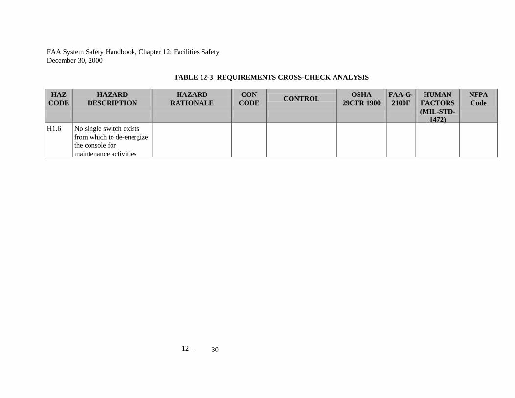
H1.6 No single switch exists from which to de-energize the console for maintenance activities

FAA System Safety Handbook, Chapter 12: Facilities Safety December 30, 2000
12 - 31
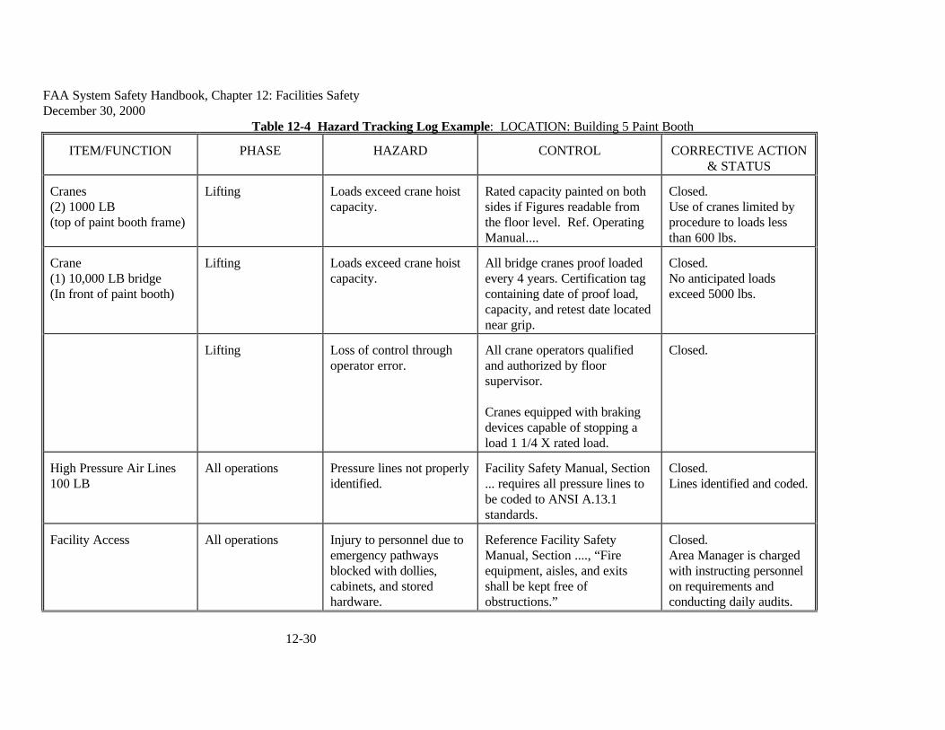
12.7 Hazard Tracking Log Example Table 12-4 is an example of a page from a Hazard Tracking Log. It could also serve as a safety analysis that might be performed by design or facility safety engineering for a paint booth. As a safety analysis, it would serve as an effective design tool reflecting analysis tailoring. It does not meet the normal definition of hazard analysis as it does not include severity or probability levels.

FAA System Safety Handbook, Chapter 12: Facilities Safety December 30, 2000
12-30
Table 12-4 Hazard Tracking Log Example: LOCATION: Building 5 Paint Booth
ITEM/FUNCTION PHASE HAZARD CONTROL CORRECTIVE ACTION & STATUS
Cranes (2) 1000 LB (top of paint booth frame)
Lifting Loads exceed crane hoist capacity.
Rated capacity painted on both sides if Figures readable from the floor level. Ref. Operating Manual....
Closed. Use of cranes limited by procedure to loads less than 600 lbs.
Crane (1) 10,000 LB bridge (In front of paint booth)
Lifting Loads exceed crane hoist capacity.
All bridge cranes proof loaded every 4 years. Certification tag containing date of proof load, capacity, and retest date located near grip.
Closed. No anticipated loads exceed 5000 lbs.
Lifting Loss of control through operator error.
All crane operators qualified and authorized by floor supervisor. Cranes equipped with braking devices capable of stopping a load 1 1/4 X rated load.
Closed.
High Pressure Air Lines 100 LB
All operations Pressure lines not properly identified.
Facility Safety Manual, Section ... requires all pressure lines to be coded to ANSI A.13.1 standards.
Closed. Lines identified and coded.
Facility Access All operations Injury to personnel due to emergency pathways blocked with dollies, cabinets, and stored hardware.
Reference Facility Safety Manual, Section ...., “Fire equipment, aisles, and exits shall be kept free of obstructions.”
Closed. Area Manager is charged with instructing personnel on requirements and conducting daily audits.

FAA System Safety Handbook, Chapter 12: Facilities Safety December 30, 2000
12-31
12.7.1 Matrices Construction Analyses matrices are designed to suit analytical needs. Matrices should be customized to enable the integration of analytical work. Matrices can be customized to present relevant information to allow continuous analysis and safety review.
12.7.2 Hazard Tracking and Risk Resolution All identified hazards should be tracked until closed out. This occurs when the hazard controls have been validated and verified. Validation is the consideration of the effectiveness and applicability of a control. System safety professionals or other designated group members conduct the validation process. Verification of a specific hazard control is the act of confirming that the control has been formally implemented. This process must also be conducted by a system safety professional or a designated group member. Each hazard control should be formally implemented as a requirement. Hazard control validation involves a detailed analysis of the particular control to determine its effectiveness, suitability, and applicability.
12.8 Equipment Evaluation and Approval A review of available Safety Assessments sometimes reveal that they focused primarily on a single Underwriters Laboratories, Inc. (UL) standard (e.g. UL 1050) instead of all of the Occupational Safety and Health Administration (OSHA) standards for the workplace. UL is an independent, not-for-profit product safety testing and certification organization whose work applies to the manufacture of products. The use of a UL standard by itself is inappropriate for comprehensive safety assessments of the workplace. OSHA’s acceptance of a product certified by a nationally recognized testing laboratory (NRTL) does not mean the product is “OSHA-approved.” It means that the NRTL has tested and certified the product to designate conformance to a specific product safety test standard(s) for a very specific issue. Listing by an NRTL such as UL, does not automatically ensure that an item can be used at an acceptable level of risk. These listings are only indications that the item has been tested and listed according to the laboratory’s criteria. These criteria may not reflect the actual risks associated with the particular application of the component or its use in a system. Hazard analysis techniques should be employed to identify these risks and implement controls to reduce them to acceptable levels. The hazard is related to the actual application of the product. A computer powered by 110 VAC might be very dangerous if not used as intended. For example, if it were used by a swimming pool, it would be dangerous regardless of the UL standard that it was manufactured to comply with. Therefore, the use of products manufactured to product manufacturing standards require the same system safety analysis as developmental items to ensure that they are manufactured to the correct standard and used in an acceptable manner. Conformance to codes, requirements, and standards is no assurance of acceptable levels of risk when performing tasks. Risks should be diagnosed by hazard analysis techniques like the O&SHA. When risks are identified, they are either eliminated or controlled to an acceptable level by the application of hazard controls.

FAA System Safety Handbook, Chapter 12: Facilities Safety December 30, 2000
12-32
Commercial-off-the-shelf, non-developmental items (COTS NDI) pose risks that must be isolated by formal hazard analysis methods. The use of COTS-NDI does not ensure that the components or systems that they are used in are OSHA compliant. COTS NDI components cannot be considered as having been manufactured to any specific standards unless they have been tested by an NRTL. Therefore, the use of COTS-NDI requires the same system safety analysis as developmental items to ensure that they are manufactured and used in an acceptable manner.
12.9 Facility and Equipment Decommissioning During activities associated with the decommissioning of a facility and/or equipment, hazardous materials may be found. There are numerous federal and state regulations governing the disposal of hazardous materials and hazardous waste. FAA equipment may contain numerous parts which contain hazardous materials such as:
• PCB capacitors and transformers
• Lead/acid, nickel/cadmium, and lithium batteries
• Beryllium heat sinks
• Cathode Ray Tube (CRT) displays containing lead and mercury
• Printed Circuit Boards (lead)
• Mercury switches and lights
• Lead and cadmium paint
• Asbestos
The identification of hazardous materials in facilities and equipment that have been designated for disposition. Failure to comply with these regulations can lead to fines, penalties, and other regulatory actions. As per the Federal Facilities Compliance Act of 1992, states and local authorities may fine and/or penalize federal officials for not complying with state and local environmental requirements. Improper disposal of equipment containing hazardous materials would expose the FAA to liability in terms of regulatory actions and lawsuits (e.g. fines, penalties, and cleanup of waste sites) There are many regulatory drivers when dealing with hazardous materials disposition. These include:
• Resource Conservation and Recovery Act (RCRA)
• Comprehensive Environmental Response, Compensation, and Liability Act (CERCLA or Superfund)
• Superfund Reauthorization Act (SARA)

FAA System Safety Handbook, Chapter 12: Facilities Safety December 30, 2000
12-33
• National Environmental Policy Act (NEPA)
• Toxic Substance Control Act (TSCA)
• Federal Facilities Compliance Act of 1992 (FFCA)
• Community Environmental Response Facilitation Act (CERFA)
• DOT Shipping Regulations - Hazardous Materials Regulation
• OSHA Regulations (HAZCOM)
• State, local, and tribal laws
• FAA Orders
• Disposal guidance provided in FAA Order 4660.8, Real Property Management and Disposal
• Disposition guidance contained in FAA Order 4800.2C, Utilization and Disposal of Excess and Surplus Personal Property
12.10 Related Codes National Fire Protection Association (NFPA) Life Safety Code. The contents of any building or structure are classified as low, ordinary, or high. Low hazard contents are classified as those of such low combustibility that no self-perpetuating fire therein can occur. Ordinary hazard contents can be classified as those likely to burn with moderate rapidity or give off a considerable volume of smoke. High hazard contents shall be classified as those likely to burn with extreme rapidity or from which explosions are likely. NFPA National Electrical Code (NEC) Locations are classified depending on the properties of the flammable vapors, liquids or gases, or combustible dusts or fibers that may be present in the likelihood that a flammable or combustible concentration or quantity is present period. NFPA Hazard (Health) Identification System Materials are classified based on their potential for causing irritation, temporary health effects, minor residual injury, major residual injury and even death.
• Material that on exposure under fire conditions would offer no hazard beyond that of ordinary combustible material. (Example: peanut oil)
• Material that on exposure would cause irritation but only minor residual injury. (Example: turpentine)
• Material that on intense or continued but not chronic exposure could cause temporary incapacitation or possible residual injury. (Example: ammonia gas)

FAA System Safety Handbook, Chapter 12: Facilities Safety December 30, 2000
12-34
• Material that on very short exposure could cause death or major residual injury. (Example: hydrogen cyanide)

FAA System Safety Handbook, Chapter 12: Facilities Safety December 30, 2000
12-35
12.11 Technical References FAA Order 1600.46, Physical Security Review of New Facilities, Office Space or Operating Areas FAA Order 3900.19, FAA Occupational Safety and Health Program. FAA Order 8040.4, Safety Risk Management. FAA Order 6000.15, General Maintenance Handbook for Airway Facilities FAA-G-2100F, Electronic Equipment, General Requirements Human Factors Design Guide. Daniel Wagner, U.S. Dept of Transportation, FAA, January 15, 1996. National Fire Protection Association, National Fire Codes Code of Federal Regulations (CFR) Some examples:
• 29 CFR (Labor/OSHA)
• 40 CFR (Protection of Environment)
• 10 CFR (Energy)
• 49 CFR (Transportation)
Public Law 91-596; Executive Order 12196, Occupational Safety and Health Programs for Federal Employees System Safety 2000, A Practical Guide for Planning, Managing, and Conducting System Safety Programs, J. Stephenson, 1991. System Safety Analysis Handbook, System Safety Society (SSS), July 1993. System Safety Engineering and Management, H. E. Roland and B. Moriarty, 1990.