Chapter 10: Phase Transformations
31
ISSUES TO ADDRESS... Transforming one phase into another takes time. Fe (Austenite) Eutectoid transformation C FCC Fe 3 C (cementite) (ferrite) + (BCC) Chapter 10: Phase Transformations
-
Upload
jael-benson -
Category
Documents
-
view
149 -
download
16
description
Chapter 10: Phase Transformations. Fe 3 C. Fe. g. Eutectoid. (cementite). transformation. +. (Austenite). a. C. (BCC). FCC. (ferrite). ISSUES TO ADDRESS. • Transforming one phase into another takes time. Phase Transformation. Nucleation and Growth. 100. - PowerPoint PPT Presentation
Transcript of Chapter 10: Phase Transformations

ISSUES TO ADDRESS...• Transforming one phase into another takes time.
Fe
(Austenite)
Eutectoid transformation
C FCC
Fe3C(cementite)
(ferrite)
+
(BCC)
Chapter 10:Phase Transformations

Phase Transformation

• Reaction rate is a result of nucleation and growth of crystals.
• Examples: Eutectoid reaction
Nucleation and Growth
% Pearlite
0
50
100
Nucleation regime
Growth regime
log (time)t0.5
Nucleation rate increases with T
Growth rate increases with T
T just below TE
Nucleation rate low
Growth rate high
pearlite colony
T moderately below TE
Nucleation rate med Growth rate med.
Nucleation rate high
T way below TE
Growth rate low

Nucleation
nuclei (seeds) act as template to grow crystals
Nucleation driving force increases as increase T– Supercooling (or undercooling)– superheating
Small supercooling few nuclei, large crystals
Large supercooling rapid nucleation, many nuclei, small crystals

Fe-Fe3C phase diagram

Solidification: Nucleation Processes
• Homogeneous nucleation – nuclei form in the bulk of liquid metal– requires supercooling (typically 80-300°C max)
• Heterogeneous nucleation– much easier since stable “nucleus” is already
present• Could be wall of mold or impurities in the
liquid phase– allows solidification with only 0.1-10ºC
supercooling

r* = critical nucleus: nuclei < r* shrink; nuclei>r* grow
Homogeneous Nucleation & Energy Effects
GT = Total Free Energy = GS + GV
Surface Free Energy- destabilizes the nuclei (energy for makinmg surface)
24 rGS = surface tension
Volume (Bulk) Free Energy – stabilizes the nuclei (releases energy)
GrGV3
3
4
volume unit
energy free volume G
TH
Tr
S
m
2* HS = latent heat of
solidification

Homogenous and Heterogeneous Nucleation

Rate of Phase Transformation
Completely growth
log t
Fra
ctio
n tr
an
sfo
rme
d, y
Fixed T: Isothermal
By convention r = 1 / t0.5
maximum rate reached –
now amount unconverted decreases so rate slowerrate increases as surface
area increases & nuclei grow

Isothermal Transformation Diagrams
• Fe-C system, Co = 0.76 wt% C• Transformation at T = 675°C.
100
50
01 102 104
T = 675°C
y,
% tr
ansf
orm
ed
time (s)
400
500
600
700
1 10 102 103 104 105
0%pearlite
100%
50%
Austenite (stable) TE (727C)Austenite (unstable)
Pearlite
T(°C)
time (s)
isothermal transformation at 675°C
675°C (T smaller)
0
50
y (%
pea
rlite
)
600°C (T larger)
650°C
100
Course pearlite formed at higher T - softer
Fine pearlite formed at lower T - harder
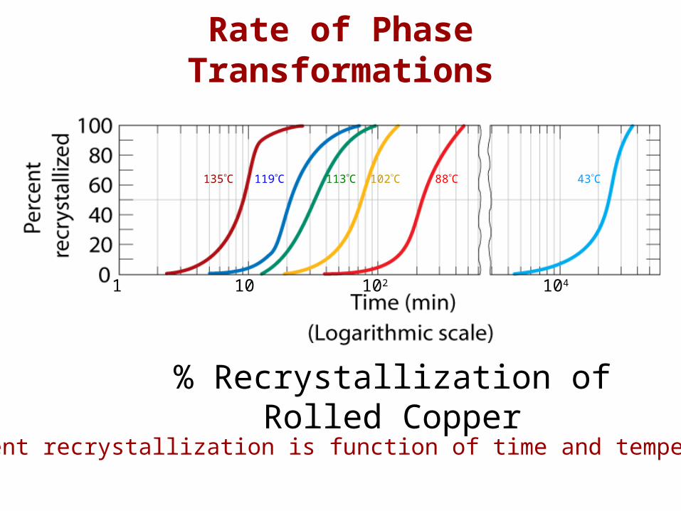
Rate of Phase Transformations
135C 119C 113C 102C 88C 43C
1 10 102 104
% Recrystallization of Rolled Copper
Percent recrystallization is function of time and temperature

Transformations & Undercooling
• Can make it occur at: ...727ºC (cool it slowly) ...below 727ºC (“undercool” it!)
• Eutectoid transformation (Fe-C System): + Fe3C0.76 wt% C
0.022 wt% C6.7 wt% C
Fe 3
C (
cem
entit
e)
1600
1400
1200
1000
800
600
4000 1 2 3 4 5 6 6.7
L
(austenite)
+L
+Fe3C
+Fe3C
L+Fe3C
(Fe) Co , wt%C
1148°C
T(°C)
ferrite
727°C
Eutectoid:Equil. Cooling: Ttransf. = 727ºC
T
Undercooling by Ttransf. < 727C
0.7
6
0.0
22

Eutectoid Transformation Rate
• Growth of pearlite from austenite:cementite (Fe3C)
Ferrite ()
pearlite
growth
direction
Diffusive flow of C needed
• Higher T give higher diffusivity

• Eutectoid composition, Co = 0.76 wt% C• Begin at T > 727°C• Rapidly cool to 625°C and hold isothermally.
Effect of Cooling History in Fe-C System
400
500
600
700
0%pearlite
100%
50%
Austenite (stable)TE (727C)
Austenite (unstable)
Pearlite
T(°C)
1 10 102 103 104 105
time (s)

Transformations with Proeutectoid Materials
Hypereutectoid composition – proeutectoid cementite
CO = 1.13 wt% C
TE (727°C)
T(°C)
time (s)
A
A
A+
C
P
1 10 102 103 104
500
700
900
600
800
A+
P
Fe 3
C (
cem
entit
e)
1600
1400
1200
1000
800
600
4000 1 2 3 4 5 6 6.7
L
(austenite)
+L
+Fe3C
+Fe3C
L+Fe3C
(Fe) Co , wt%C
T(°C)
727°CT
0.7
6
0.0
22
1.13

T-T-T of Eutectoid Composition
A – AusteniteP – PearliteB – BainiteM – MartensiteC – Cementite

Non-Equilibrium Transformation Products: Fe-C
• Bainite: -- lathes (strips) with long
rods of Fe3C --diffusion controlled.• Isothermal Transf. Diagram
Fe3C
(cementite)
5 m
(ferrite)
10 103 105
time (s)10-1
400
600
800
T(°C)Austenite (stable)
200
P
B
TE
0%
100%
50%
pearlite/bainite boundary
A
A
100% bainite
100% pearlite
T-T-T DiagramTime – Temperature – Transformation

• Spheroidite: -- grains with
spherical Fe3C -- diffusion
dependent. -- heat bainite or
pearlite for long times near TE
Spheroidite: Fe-C System
60 m
(ferrite)
(cementite)
Fe3C

• Martensite: --(FCC) to Martensite (BCT)
• Isothermal Transf. Diagram
• to M transformation -- is rapid! -- % transformation
depends on T only.
Martensite: Fe-C System
Martensite needlesAustenite
60
m
10 103 105 time (s)10-1
400
600
800
T(°C)Austenite (stable)
200
P
B
TE
0%
100%50%
A
A
M + AM + A
M + A
0%50%90%
xx x
xx
xpotential C atom sites
Fe atom sites

(FCC) P (BCC) + Fe3C
Martensite Formation
slow cooling
tempering
quench
M (BCT)
M = martensite is body centered tetragonal (BCT)
Diffusionless transformation BCT if C > 0.15 wt%
BCT few slip planes hard, brittle

Phase Transformations of Alloys
Effect of adding other elements
Change transition temp.
Cr, Ni, Mo, Si, Mn
retard +
Fe3C
transformation
Alloy steel (type 4340)

Continuous Cooling Curve
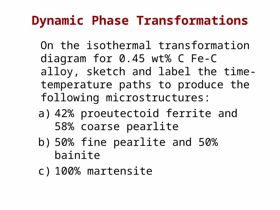
Dynamic Phase Transformations
On the isothermal transformation diagram for 0.45 wt% C Fe-C alloy, sketch and label the time-temperature paths to produce the following microstructures:
a) 42% proeutectoid ferrite and 58% coarse pearlite
b) 50% fine pearlite and 50% bainite
c) 100% martensite

A + B
A + P
A + A
BP
A50%
0
200
400
600
800
0.1 10 103 105
time (s)
M (start)M (50%)M (90%)
Example Problem for Co = 0.45 wt%
a) 42% proeutectoid ferrite and 58% coarse pearlite
first make ferrite
then pearlite
course pearlite
higher T
T (°C)

b) 50% fine pearlite and 50% bainite
first make pearlite
then bainite
fine pearlite
lower T
T (°C)
A + B
A + P
A + A
BP
A50%
0
200
400
600
800
0.1 10 103 105
time (s)
M (start)M (50%)M (90%)
Example Problem for Co = 0.45 wt%

A + B
A + P
A + A
BP
A50%
0
200
400
600
800
0.1 10 103 105
time (s)
M (start)M (50%)M (90%)
Example Problem for Co = 0.45 wt%
c) 100 % martensite – quench = rapid cool
c)
T (°C)

Mechanical Prop: Fe-C System (1)
• More wt% C: TS and YS increase , %EL decreases.
• Effect of wt% C
Co < 0.76 wt% C
Hypoeutectoid
Pearlite (med)ferrite (soft)
Co > 0.76 wt% C
Hypereutectoid
Pearlite (med)Cementite
(hard)
300
500
700
900
1100YS(MPa)TS(MPa)
wt% C0 0.5 1
hardness
0.7
6
Hypo Hyper
wt% C0 0.5 1
0
50
100%EL
Imp
act
en
erg
y (I
zod
, ft
-lb
)
0
40
80
0.7
6
Hypo Hyper

Mechanical Prop: Fe-C System (2)
• Fine vs coarse pearlite vs spheroidite
• Hardness:
• %RA:
fine > coarse > spheroiditefine < coarse < spheroidite
80
160
240
320
wt%C0 0.5 1
Bri
ne
ll h
ard
ne
ss
fine pearlite
coarse pearlitespheroidite
Hypo Hyper
0
30
60
90
wt%C
Du
ctili
ty (
%R
A)
fine pearlite
coarse pearlite
spheroidite
Hypo Hyper
0 0.5 1

Mechanical Prop: Fe-C System (3)
• Fine Pearlite vs Martensite:
• Hardness: Fine Pearlite << Martensite.
0
200
wt% C0 0.5 1
400
600
Bri
ne
ll h
ard
ne
ss martensite
fine pearlite
Hypo Hyper
• Hardness: Pearlite < Bainite.

Tempering Martensite• reduces brittleness of martensite,• reduces internal stress caused by quenching.
• decreases TS, YS but increases %RA• produces extremely small Fe3C particles surrounded by
9 m
YS(MPa)TS(MPa)
800
1000
1200
1400
1600
1800
30
40
50
60
200 400 600Tempering T (°C)
%RA
TS
YS
%RA

Summary: Processing Options
Austenite ()
Bainite( + Fe3C plates/needles)
Pearlite( + Fe3C layers + a proeutectoid phase)
Martensite(BCT phase diffusionless
transformation)
Tempered Martensite ( + very fine Fe3C particles)
slow cool
moderate cool
rapid quench
reheat
Str
engt
h
Duc
tility
Martensite T Martensite
bainite fine pearlite
coarse pearlite spheroidite
General Trends