Chapter 10 Configure a Site-to-Site IPsec VPN between an ... · Use the CLI command script to...
22
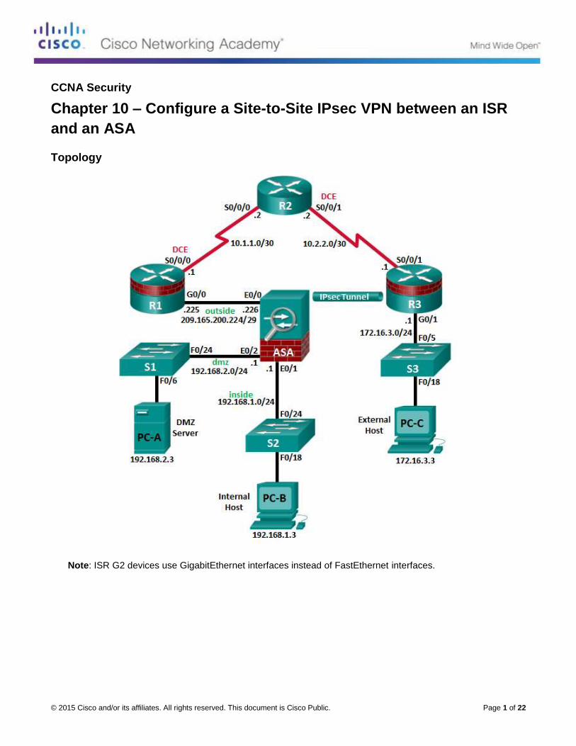
© 2015 Cisco and/or its affiliates. All rights reserved. This document is Cisco Public. Page 1 of 22 CCNA Security Chapter 10 – Configure a Site-to-Site IPsec VPN between an ISR and an ASA Topology Note: ISR G2 devices use GigabitEthernet interfaces instead of FastEthernet interfaces.
Transcript of Chapter 10 Configure a Site-to-Site IPsec VPN between an ... · Use the CLI command script to...
© 2015 Cisco and/or its affiliates. All rights reserved. This document is Cisco Public. Page 1 of 22
CCNA Security
Chapter 10 – Configure a Site-to-Site IPsec VPN between an ISR
and an ASA
Topology
Note: ISR G2 devices use GigabitEthernet interfaces instead of FastEthernet interfaces.

CCNA Security Chapter 10 Lab B
© 2015 Cisco and/or its affiliates. All rights reserved. This document is Cisco Public. Page 2 of 22
IP Addressing Table
Device Interface IP Address Subnet Mask Default Gateway Switch Port
R1 G0/0 209.165.200.225 255.255.255.248 N/A ASA E0/0
S0/0/0 (DCE) 10.1.1.1 255.255.255.252 N/A N/A
R2 S0/0/0 10.1.1.2 255.255.255.252 N/A N/A
S0/0/1 (DCE) 10.2.2.2 255.255.255.252 N/A N/A
R3 G0/1 172.16.3.1 255.255.255.0 N/A S3 F0/5
S0/0/1 10.2.2.1 255.255.255.252 N/A N/A
ASA
VLAN 1 (E0/1) 192.168.1.1 255.255.255.0 NA S2 Fa0/24
VLAN 2 (E0/0) 209.165.200.226 255.255.255.248 NA R1 F0/0
VLAN 3 (E0/2) 192.168.2.1 255.255.255.0 NA S1 F0/24
PC-A NIC 192.168.2.3 255.255.255.0 192.168.2.1 S1 F0/6
PC-B NIC 192.168.1.3 255.255.255.0 192.168.1.1 S2 F0/18
PC-C NIC 172.16.3.3 255.255.255.0 172.16.3.1 S3 F0/18
Objectives
Part 1: Basic Router/Switch/PC Configuration
Cable the network and clear previous device settings, as shown in the topology.
Configure basic settings for routers.
Configure PC host IP settings.
Verify connectivity.
Save the basic running configuration for each router and switch.
Part 2: Accessing the ASA Console and ASDM
Access the ASA console.
Clear the previous ASA configuration settings.
Bypass Setup mode.
Use the CLI command script to configure the ASA.
Verify HTTP ASDM access.
Part 3: Configuring the ISR as a Site-to-Site IPsec VPN Endpoint Using the CLI
Configure basic VPN connection information settings.
Specify IKE policy parameters.
Configure a transform set.
Specify traffic to protect.
Review the summary of the configuration.
Review the site-to-site VPN tunnel configuration.

CCNA Security Chapter 10 Lab B
© 2015 Cisco and/or its affiliates. All rights reserved. This document is Cisco Public. Page 3 of 22
Part 4: Configuring the ASA as a Site-to-Site IPsec VPN Endpoint Using ASDM
Access ASDM.
Review the ASDM Home screen.
Start the VPN wizard.
Configure peer device identification.
Specify the traffic to protect.
Configure authentication.
Configure miscellaneous settings.
Review the configuration summary and deliver the commands to the ASA.
Verify the ASDM VPN connection profile.
Use ASDM monitoring to verify the tunnel.
Background/Scenario
In addition to acting as a remote access VPN concentrator, the ASA can provide site-to-site IPsec VPN tunneling. The tunnel can be configured between two ASAs or between an ASA and another IPsec VPN-capable device, such as an ISR, as is the case with this lab.
Your company has two locations connected to an ISP. R1 represents a customer-premise equipment (CPE) device managed by the ISP. R2 represents an intermediate Internet router. R3 connects users at the remote branch office to the ISP. The ASA is an edge security device that connects the internal corporate network and DMZ to the ISP while providing NAT services to inside hosts.
Management has asked you to provide a dedicated site-to-site IPsec VPN tunnel between the ISR router at the remote branch office and the ASA device at the corporate site. This tunnel will protect traffic between the branch office LAN and the corporate LAN, as it passes through the Internet. The site-to-site VPN does not require a VPN client on the remote or corporate site host computers. Traffic from either LAN to other Internet destinations is routed by the ISP and is not protected by the VPN tunnel. The VPN tunnel will pass through R1 and R2; both routers are not aware of the tunnel’s existence.
In Part 1 of this lab, you will configure the topology and non-ASA devices. In Part 2, you will prepare the ASA for ASDM access. In Part 3, you will use the CLI to configure the R3 ISR as a site-to-site IPsec VPN endpoint. In Part 4, you will configure the ASA as a site-to-site IPsec VPN endpoint using the ASDM VPN wizard.
Note: The router commands and output in this lab are from a Cisco 1941 router with Cisco IOS Release 15.4(3)M2 (with a Security Technology Package license). Other routers and Cisco IOS versions can be used. See the Router Interface Summary Table at the end of this lab to determine which interface identifiers to use based on the equipment in the lab. Depending on the router model and Cisco IOS version, the commands available and the output produced might vary from what is shown in this lab.
The ASA used with this lab is a Cisco model 5505 with an 8-port integrated switch, running OS version 9.2(3) and ASDM version 7.4(1) and comes with a Base license that allows a maximum of three VLANs.
Note: Before beginning, ensure that the routers and switches have been erased and have no startup configurations.
Required Resources
1 ASA 5505 (OS version 9.2(3) and ASDM version 7.4(1) and Base license or comparable)
3 routers (Cisco 1941 with Cisco IOS Release 15.4(3)M2 image with a Security Technology package
license)
3 switches (Cisco 2960 or comparable) (not required)
CCNA Security Chapter 10 Lab B
© 2015 Cisco and/or its affiliates. All rights reserved. This document is Cisco Public. Page 4 of 22
3 PCs (Windows 7 or Windows 8.1, with SSH Client software installed)
Serial and Ethernet cables, as shown in the topology
Console cables to configure Cisco networking devices
Part 1: Basic Router/Switch/PC Configuration
In Part 1, you will set up the network topology and configure basic settings on the routers, such as interface IP addresses and static routing.
Note: Do not configure any ASA settings at this time.
Step 1: Cable the network and clear previous device settings.
Attach the devices shown in the topology diagram and cable as necessary. Ensure that the routers and
switches have been erased and have no startup configurations.
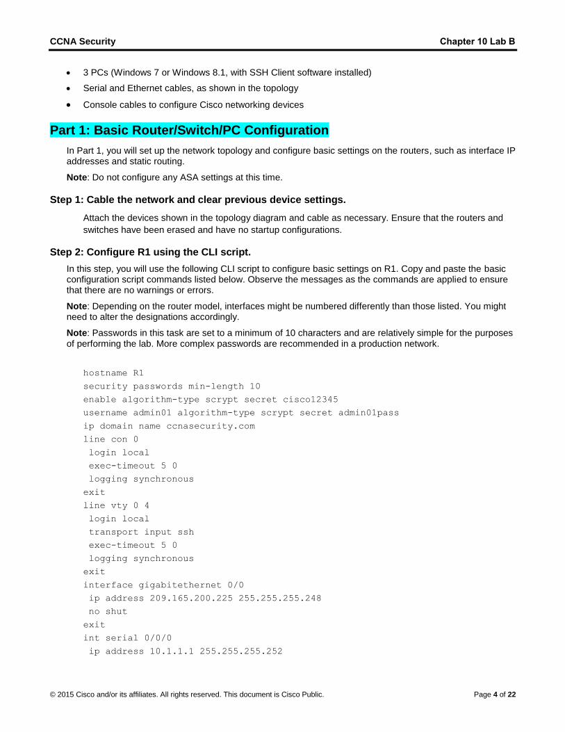
Step 2: Configure R1 using the CLI script.
In this step, you will use the following CLI script to configure basic settings on R1. Copy and paste the basic configuration script commands listed below. Observe the messages as the commands are applied to ensure that there are no warnings or errors.
Note: Depending on the router model, interfaces might be numbered differently than those listed. You might need to alter the designations accordingly.
Note: Passwords in this task are set to a minimum of 10 characters and are relatively simple for the purposes of performing the lab. More complex passwords are recommended in a production network.
hostname R1
security passwords min-length 10
enable algorithm-type scrypt secret cisco12345
username admin01 algorithm-type scrypt secret admin01pass
ip domain name ccnasecurity.com
line con 0
login local
exec-timeout 5 0
logging synchronous
exit
line vty 0 4
login local
transport input ssh
exec-timeout 5 0
logging synchronous
exit
interface gigabitethernet 0/0
ip address 209.165.200.225 255.255.255.248
no shut
exit
int serial 0/0/0
ip address 10.1.1.1 255.255.255.252
CCNA Security Chapter 10 Lab B
© 2015 Cisco and/or its affiliates. All rights reserved. This document is Cisco Public. Page 5 of 22
clock rate 2000000
no shut
exit
ip route 0.0.0.0 0.0.0.0 Serial0/0/0
crypto key generate rsa general-keys modulus 1024
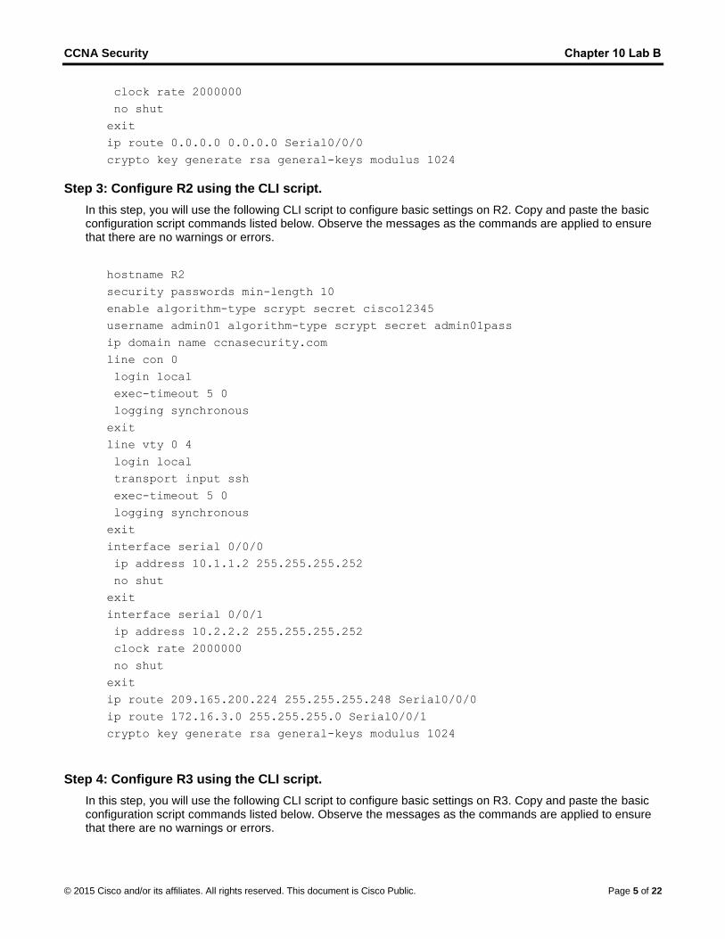
Step 3: Configure R2 using the CLI script.
In this step, you will use the following CLI script to configure basic settings on R2. Copy and paste the basic configuration script commands listed below. Observe the messages as the commands are applied to ensure that there are no warnings or errors.
hostname R2
security passwords min-length 10
enable algorithm-type scrypt secret cisco12345
username admin01 algorithm-type scrypt secret admin01pass
ip domain name ccnasecurity.com
line con 0
login local
exec-timeout 5 0
logging synchronous
exit
line vty 0 4
login local
transport input ssh
exec-timeout 5 0
logging synchronous
exit
interface serial 0/0/0
ip address 10.1.1.2 255.255.255.252
no shut
exit
interface serial 0/0/1
ip address 10.2.2.2 255.255.255.252
clock rate 2000000
no shut
exit
ip route 209.165.200.224 255.255.255.248 Serial0/0/0
ip route 172.16.3.0 255.255.255.0 Serial0/0/1
crypto key generate rsa general-keys modulus 1024
Step 4: Configure R3 using the CLI script.
In this step, you will use the following CLI script to configure basic settings on R3. Copy and paste the basic configuration script commands listed below. Observe the messages as the commands are applied to ensure that there are no warnings or errors.

CCNA Security Chapter 10 Lab B
© 2015 Cisco and/or its affiliates. All rights reserved. This document is Cisco Public. Page 6 of 22
hostname R3
security passwords min-length 10
enable algorithm-type scrypt secret cisco12345
username admin01 algorithm-type scrypt secret admin01pass
ip domain name ccnasecurity.com
line con 0
login local
exec-timeout 5 0
logging synchronous
exit
line vty 0 4
login local
transport input ssh
exec-timeout 5 0
logging synchronous
exit
interface gigabitethernet 0/1
ip address 172.16.3.1 255.255.255.0
no shut
exit
int serial 0/0/1
ip address 10.2.2.1 255.255.255.252
no shut
exit
ip route 0.0.0.0 0.0.0.0 Serial0/0/1
crypto key generate rsa general-keys modulus 1024
Step 5: Configure PC host IP settings.
Configure a static IP address, subnet mask, and default gateway for PC-A, PC-B, and PC-C as shown in the IP Addressing table.
Step 6: Verify connectivity.
Because the ASA is the focal point for the network zones, and it has not yet been configured, there will be no connectivity between devices that are connected to it. However, PC-C should be able to ping the R1 interface G0/0. From PC-C, ping the R1 G0/0 IP address (209.165.200.225). If these pings are unsuccessful, troubleshoot the basic device configurations before continuing.
Note: If you can ping from PC-C to R1 G0/0 and S0/0/0, you have demonstrated that static routing is configured and functioning correctly.
Save the running configuration for each router.
Part 2: Accessing the ASA Console and ASDM
Step 1: Clear the previous ASA configuration settings.
a. Use the write erase command to remove the startup-config file from flash memory.
CCNA Security Chapter 10 Lab B
© 2015 Cisco and/or its affiliates. All rights reserved. This document is Cisco Public. Page 7 of 22
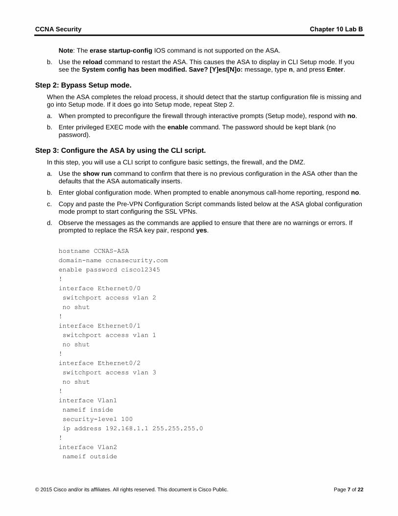
Note: The erase startup-config IOS command is not supported on the ASA.
b. Use the reload command to restart the ASA. This causes the ASA to display in CLI Setup mode. If yousee the System config has been modified. Save? [Y]es/[N]o: message, type n, and press Enter.
Step 2: Bypass Setup mode.
When the ASA completes the reload process, it should detect that the startup configuration file is missing and go into Setup mode. If it does go into Setup mode, repeat Step 2.
a. When prompted to preconfigure the firewall through interactive prompts (Setup mode), respond with no.
b. Enter privileged EXEC mode with the enable command. The password should be kept blank (nopassword).
Step 3: Configure the ASA by using the CLI script.
In this step, you will use a CLI script to configure basic settings, the firewall, and the DMZ.
a. Use the show run command to confirm that there is no previous configuration in the ASA other than thedefaults that the ASA automatically inserts.
b. Enter global configuration mode. When prompted to enable anonymous call-home reporting, respond no.
c. Copy and paste the Pre-VPN Configuration Script commands listed below at the ASA global configurationmode prompt to start configuring the SSL VPNs.
d. Observe the messages as the commands are applied to ensure that there are no warnings or errors. Ifprompted to replace the RSA key pair, respond yes.
hostname CCNAS-ASA
domain-name ccnasecurity.com
enable password cisco12345
!
interface Ethernet0/0
switchport access vlan 2
no shut
!
interface Ethernet0/1
switchport access vlan 1
no shut
!
interface Ethernet0/2
switchport access vlan 3
no shut
!
interface Vlan1
nameif inside
security-level 100
ip address 192.168.1.1 255.255.255.0
!
interface Vlan2
nameif outside
CCNA Security Chapter 10 Lab B
© 2015 Cisco and/or its affiliates. All rights reserved. This document is Cisco Public. Page 8 of 22
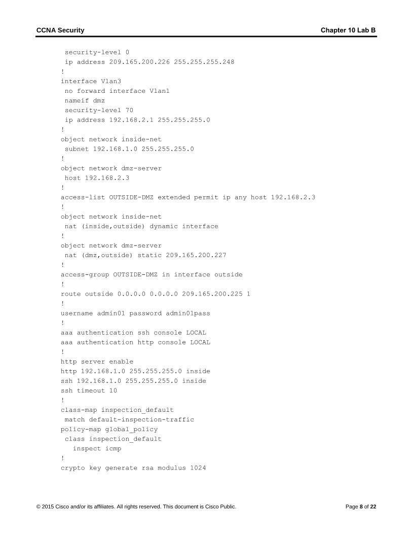
security-level 0
ip address 209.165.200.226 255.255.255.248
!
interface Vlan3
no forward interface Vlan1
nameif dmz
security-level 70
ip address 192.168.2.1 255.255.255.0
!
object network inside-net
subnet 192.168.1.0 255.255.255.0
!
object network dmz-server
host 192.168.2.3
!
access-list OUTSIDE-DMZ extended permit ip any host 192.168.2.3
!
object network inside-net
nat (inside,outside) dynamic interface
!
object network dmz-server
nat (dmz,outside) static 209.165.200.227
!
access-group OUTSIDE-DMZ in interface outside
!
route outside 0.0.0.0 0.0.0.0 209.165.200.225 1
!
username admin01 password admin01pass
!
aaa authentication ssh console LOCAL
aaa authentication http console LOCAL
!
http server enable
http 192.168.1.0 255.255.255.0 inside
ssh 192.168.1.0 255.255.255.0 inside
ssh timeout 10
!
class-map inspection_default
match default-inspection-traffic
policy-map global_policy
class inspection_default
inspect icmp
!
crypto key generate rsa modulus 1024

CCNA Security Chapter 10 Lab B
© 2015 Cisco and/or its affiliates. All rights reserved. This document is Cisco Public. Page 9 of 22
e. At the privileged EXEC mode prompt, issue the write mem (or copy run start) command to save therunning configuration to the startup configuration and the RSA keys to non-volatile memory.
Part 3: Configuring the ISR as a Site-to-Site IPsec VPN Endpoint Using the
CLI
In Part 3 of this lab, you will configure R3 as an IPsec VPN endpoint for the tunnel between R3 and the ASA. R1 and R2 are unaware of the tunnel.
Step 1: Verify connectivity from the R3 LAN to the ASA.
In this step, you will verify that PC-C on the R3 LAN can ping the ASA outside interface.
Ping the ASA IP address of 209.165.200.226 from PC-C.
PC-C:\> ping 209.165.200.226
If the pings are unsuccessful, troubleshoot the basic device configurations before continuing.
Step 2: Enable IKE policies on R3.
IPsec is an open framework that allows for the exchange of security protocols as new technologies and encryption algorithms are developed.
There are two central configuration elements in the implementation of an IPsec VPN:
Implement Internet Key Exchange (IKE) parameters.
Implement IPsec parameters.
a. Verify that IKE is supported and enabled.
IKE Phase 1 defines the key exchange method used to pass and validate IKE policies between peers. InIKE Phase 2, the peers exchange and match IPsec policies for the authentication and encryption of datatraffic.
IKE must be enabled for IPsec to function. IKE is enabled, by default, on IOS images with cryptographicfeature sets. If it is disabled, you can enable it with the crypto isakmp enable command. Use thiscommand to verify that the router IOS supports IKE and that it is enabled.
R3(config)# crypto isakmp enable
Note: If you cannot execute this command on the router, you must upgrade to the IOS image thatincludes the Cisco cryptographic services.
b. Establish an ISAKMP policy and view the available options.
To allow IKE Phase 1 negotiation, you must create an ISAKMP policy and configure a peer associationinvolving that ISAKMP policy. An ISAKMP policy defines the authentication and encryption algorithms,and the hash function used to send control traffic between the two VPN endpoints. When an ISAKMPsecurity association has been accepted by the IKE peers, IKE Phase 1 has been completed. IKE Phase 2parameters will be configured later.
Issue the crypto isakmp policy number global configuration mode command on R1 for policy 10.
R1(config)# crypto isakmp policy 10
CCNA Security Chapter 10 Lab B
© 2015 Cisco and/or its affiliates. All rights reserved. This document is Cisco Public. Page 10 of 22
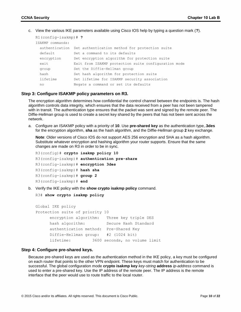
c. View the various IKE parameters available using Cisco IOS help by typing a question mark (?).
R1(config-isakmp)# ?
ISAKMP commands:
authentication Set authentication method for protection suite
default Set a command to its defaults
encryption Set encryption algorithm for protection suite
exit Exit from ISAKMP protection suite configuration mode
group Set the Diffie-Hellman group
hash Set hash algorithm for protection suite
lifetime Set lifetime for ISAKMP security association
no Negate a command or set its defaults
Step 3: Configure ISAKMP policy parameters on R3.
The encryption algorithm determines how confidential the control channel between the endpoints is. The hash algorithm controls data integrity, which ensures that the data received from a peer has not been tampered with in transit. The authentication type ensures that the packet was sent and signed by the remote peer. The Diffie-Hellman group is used to create a secret key shared by the peers that has not been sent across the network.
a. Configure an ISAKMP policy with a priority of 10. Use pre-shared key as the authentication type,.3desfor the encryption algorithm, sha as the hash algorithm, and the Diffie-Hellman group 2 key exchange.
Note: Older versions of Cisco IOS do not support AES 256 encryption and SHA as a hash algorithm.Substitute whatever encryption and hashing algorithm your router supports. Ensure that the samechanges are made on R3 in order to be in sync.
R3(config)# crypto isakmp policy 10
R3(config-isakmp)# authentication pre-share
R3(config-isakmp)# encryption 3des
R3(config-isakmp)# hash sha
R3(config-isakmp)# group 2
R3(config-isakmp)# end
b. Verify the IKE policy with the show crypto isakmp policy command.
R3# show crypto isakmp policy
Global IKE policy
Protection suite of priority 10
encryption algorithm: Three key triple DES
hash algorithm: Secure Hash Standard
authentication method: Pre-Shared Key
Diffie-Hellman group: #2 (1024 bit)
lifetime: 3600 seconds, no volume limit
Step 4: Configure pre-shared keys.
Because pre-shared keys are used as the authentication method in the IKE policy, a key must be configured on each router that points to the other VPN endpoint. These keys must match for authentication to be successful. The global configuration mode crypto isakmp key key-string address ip-address command is used to enter a pre-shared key. Use the IP address of the remote peer. The IP address is the remote interface that the peer would use to route traffic to the local router.
CCNA Security Chapter 10 Lab B
© 2015 Cisco and/or its affiliates. All rights reserved. This document is Cisco Public. Page 11 of 22
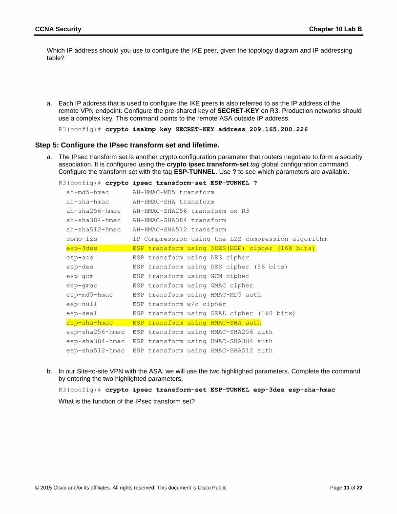
Which IP address should you use to configure the IKE peer, given the topology diagram and IP addressing table?
a. Each IP address that is used to configure the IKE peers is also referred to as the IP address of theremote VPN endpoint. Configure the pre-shared key of SECRET-KEY on R3. Production networks shoulduse a complex key. This command points to the remote ASA outside IP address.
R3(config)# crypto isakmp key SECRET-KEY address 209.165.200.226
Step 5: Configure the IPsec transform set and lifetime.
a. The IPsec transform set is another crypto configuration parameter that routers negotiate to form a securityassociation. It is configured using the crypto ipsec transform-set tag global configuration command.Configure the transform set with the tag ESP-TUNNEL. Use ? to see which parameters are available.
R3(config)# crypto ipsec transform-set ESP-TUNNEL ?
ah-md5-hmac AH-HMAC-MD5 transform
ah-sha-hmac AH-HMAC-SHA transform
ah-sha256-hmac AH-HMAC-SHA256 transform on R3
ah-sha384-hmac AH-HMAC-SHA384 transform
ah-sha512-hmac AH-HMAC-SHA512 transform
comp-lzs IP Compression using the LZS compression algorithm
esp-3des ESP transform using 3DES(EDE) cipher (168 bits)
esp-aes ESP transform using AES cipher
esp-des ESP transform using DES cipher (56 bits)
esp-gcm ESP transform using GCM cipher
esp-gmac ESP transform using GMAC cipher
esp-md5-hmac ESP transform using HMAC-MD5 auth
esp-null ESP transform w/o cipher
esp-seal ESP transform using SEAL cipher (160 bits)
esp-sha-hmac ESP transform using HMAC-SHA auth
esp-sha256-hmac ESP transform using HMAC-SHA256 auth
esp-sha384-hmac ESP transform using HMAC-SHA384 auth
esp-sha512-hmac ESP transform using HMAC-SHA512 auth
b. In our Site-to-site VPN with the ASA, we will use the two highlitghed parameters. Complete the commandby entering the two highlighted parameters.
R3(config)# crypto ipsec transform-set ESP-TUNNEL esp-3des esp-sha-hmac
What is the function of the IPsec transform set?

CCNA Security Chapter 10 Lab B
© 2015 Cisco and/or its affiliates. All rights reserved. This document is Cisco Public. Page 12 of 22
Step 6: Define interesting traffic.
To make use of the IPsec encryption with the VPN, it is necessary to define extended access lists to tell the router which traffic to encrypt. A packet that is permitted by an access list used for defining IPsec traffic is encrypted if the IPsec session is configured correctly. A packet that is denied by one of these access lists is not dropped. The packet is sent unencrypted. Also, like any other access list, there is an implicit deny at the end, which means the default action is to not encrypt traffic. If there is no IPsec security association correctly configured, no traffic is encrypted and traffic is forwarded unencrypted.
In this scenario, from the perspective of R3, the traffic you want to encrypt is traffic going from R3’s Ethernet LAN to the ASA inside LAN or vice versa from the perspective of the ASA.
a. Configure the IPsec VPN interesting traffic ACL on R3.
R3(config)# ip access-list extended VPN-ACL
R3(config-ext-nacl)# remark Link to the CCNAS-ASA
R3(config-ext-nacl)# permit ip 172.16.3.0 0.0.0.255 192.168.1.0 0.0.0.255
R3(config-ext-nacl)# exit
Does IPsec evaluate whether the access lists are mirrored as a requirement to negotiate its securityassociation?
Step 7: Create and apply a crypto map.
A crypto map associates traffic that matches an access list to a peer and various IKE and IPsec settings. After the crypto map is created, it can be applied to one or more interfaces. The interfaces that it is applied to should be the interfaces facing the IPsec peer.
To create a crypto map, use the crypto map name sequence-num type global configuration command to enter crypto map configuration mode for that sequence number. Multiple crypto map statements can belong to the same crypto map and are evaluated in ascending numerical order.
a. Create the crypto map on R3, name it S2S-MAP, and use 10 as the sequence number. Use a type ofipsec-isakmp, which means IKE is used to establish IPsec security associations. A message displaysafter the command is issued.
R3(config)# crypto map S2S-MAP 10 ipsec-isakmp
% NOTE: This new crypto map will remain disabled until a peer
and a valid access list have been configured.
R3(config-crypto-map)#
b. Use the match address access-list command to specify which access list defines which traffic to encrypt.
R3(config-crypto-map)# match address VPN-ACL
c. Setting a peer IP or hostname is required. Set it to the ASA remote VPN endpoint interface using thefollowing command.
R3(config-crypto-map)# set peer 209.165.200.226
d. Use the set transform-set tag command to hard code the transform set to be used with this peer.
R3(config-crypto-map)# set transform-set ESP-TUNNEL
R3(config-crypto-map)# exit
e. Apply the crypto map to interfaces.
CCNA Security Chapter 10 Lab B
© 2015 Cisco and/or its affiliates. All rights reserved. This document is Cisco Public. Page 13 of 22
Note: The SAs are not established until the crypto map has been activated by interesting traffic. The router generates a notification that crypto is now on.
Apply the crypto maps to the R3 Serial 0/0/1 interface.
R3(config)# interface Serial0/0/1
R3(config-if)# crypto map S2S-MAP
R3(config-if)# end
R3#
*Mar 9 06:23:03.863: %CRYPTO-6-ISAKMP_ON_OFF: ISAKMP is ON
R3#
Part 4: Configuring the ASA as a Site-to-Site IPsec VPN Endpoint Using
ASDM
In Part 4 of this lab, you will configure the ASA as an IPsec VPN tunnel endpoint. The tunnel between the ASA and R3 passes through R1 and R2.
Step 1: Access ASDM.
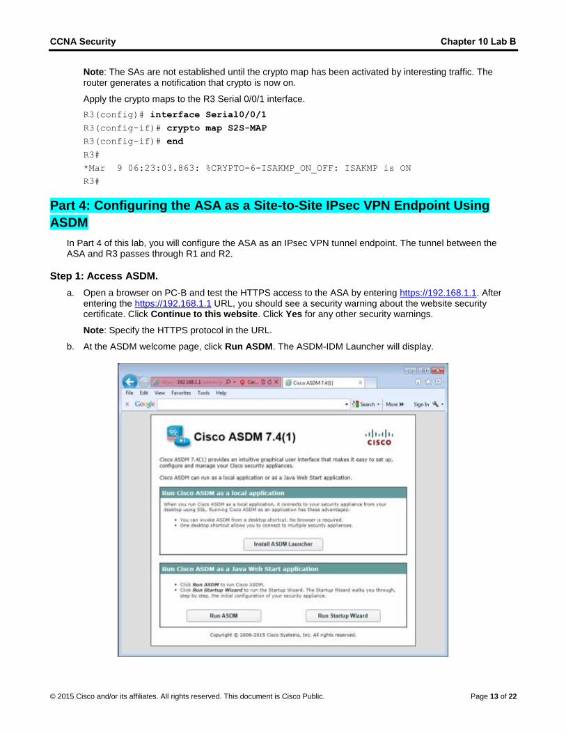
a. Open a browser on PC-B and test the HTTPS access to the ASA by entering https://192.168.1.1. Afterentering the https://192.168.1.1 URL, you should see a security warning about the website securitycertificate. Click Continue to this website. Click Yes for any other security warnings.
Note: Specify the HTTPS protocol in the URL.
b. At the ASDM welcome page, click Run ASDM. The ASDM-IDM Launcher will display.
CCNA Security Chapter 10 Lab B
© 2015 Cisco and/or its affiliates. All rights reserved. This document is Cisco Public. Page 14 of 22
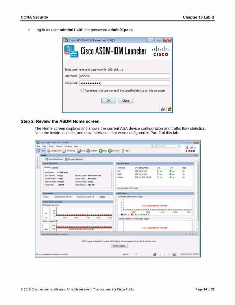
c. Log in as user admin01 with the password admin01pass.
Step 2: Review the ASDM Home screen.
The Home screen displays and shows the current ASA device configuration and traffic flow statistics. Note the inside, outside, and dmz interfaces that were configured in Part 2 of this lab.

CCNA Security Chapter 10 Lab B
© 2015 Cisco and/or its affiliates. All rights reserved. This document is Cisco Public. Page 15 of 22
Step 3: Start the VPN wizard.
a. On the ASDM main menu, click Wizards > VPN Wizards > Site-to-Site VPN Wizard to open the Site-to-Site VPN Connection Setup Wizard Introduction window.
b. Review the on-screen text and topology diagram and click Next to continue.
Step 4: Configure peer device identification.
In the Peer Device Identification window, enter the IP address of the R3 Serial0/0/1 interface (10.2.2.1) as the Peer IP Address. Leave the default VPN Access Interface set to outside. The VPN tunnel will be between R3 S0/0/1 and the ASA outside interface (VLAN 2 E0/0). Click Next to continue.
CCNA Security Chapter 10 Lab B
© 2015 Cisco and/or its affiliates. All rights reserved. This document is Cisco Public. Page 16 of 22
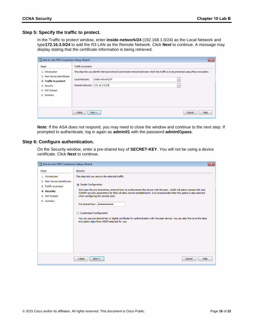
Step 5: Specify the traffic to protect.
In the Traffic to protect window, enter inside-network/24 (192.168.1.0/24) as the Local Network and type172.16.3.0/24 to add the R3 LAN as the Remote Network. Click Next to continue. A message may display stating that the certificate information is being retrieved.
Note: If the ASA does not respond, you may need to close the window and continue to the next step. If prompted to authenticate, log in again as admin01 with the password admin01pass.
Step 6: Configure authentication.
On the Security window, enter a pre-shared key of SECRET-KEY. You will not be using a device certificate. Click Next to continue.
CCNA Security Chapter 10 Lab B
© 2015 Cisco and/or its affiliates. All rights reserved. This document is Cisco Public. Page 17 of 22
Step 7: Configure miscellaneous settings.
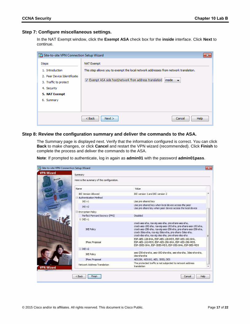
In the NAT Exempt window, click the Exempt ASA check box for the inside interface. Click Next to continue.
Step 8: Review the configuration summary and deliver the commands to the ASA.
The Summary page is displayed next. Verify that the information configured is correct. You can click Back to make changes, or click Cancel and restart the VPN wizard (recommended). Click Finish to complete the process and deliver the commands to the ASA.
Note: If prompted to authenticate, log in again as admin01 with the password admin01pass.
CCNA Security Chapter 10 Lab B
© 2015 Cisco and/or its affiliates. All rights reserved. This document is Cisco Public. Page 18 of 22
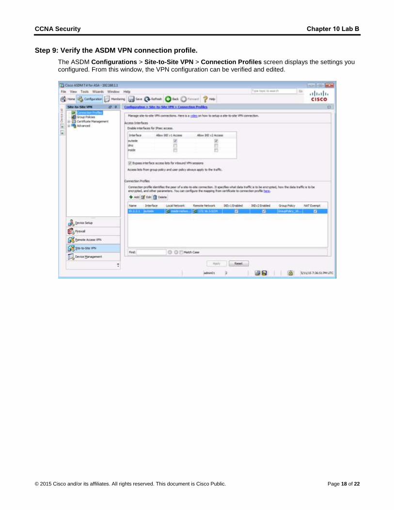
Step 9: Verify the ASDM VPN connection profile.
The ASDM Configurations > Site-to-Site VPN > Connection Profiles screen displays the settings you configured. From this window, the VPN configuration can be verified and edited.

CCNA Security Chapter 10 Lab B
© 2015 Cisco and/or its affiliates. All rights reserved. This document is Cisco Public. Page 19 of 22
Step 10: Use ASDM monitoring to verify the tunnel.
On the ASDM menu bar, click Monitoring > VPN from the panels at the lower left of the screen. Click VPN Statistics > Sessions. Notice how there is no active session. This is because the VPN tunnel has not been established.
Step 11: Test the VPN configuration from PC-B.
a. To establish the VPN tunnel, interesting traffic must be generated. From PC-B, ping PC-C.
b. This generates interesting traffic. Notice how two pings failed before being successful. This is becausethe tunnel first had to be negotiated and established before the ICMP packets could be successful.
CCNA Security Chapter 10 Lab B
© 2015 Cisco and/or its affiliates. All rights reserved. This document is Cisco Public. Page 20 of 22
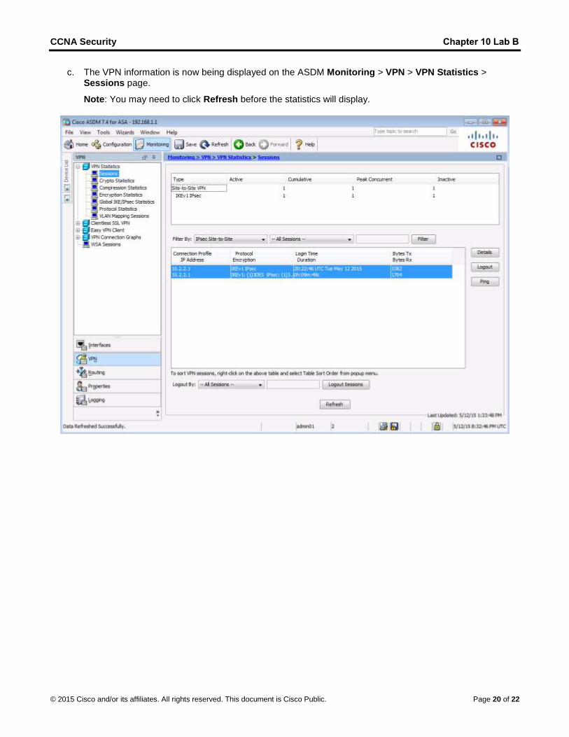
c. The VPN information is now being displayed on the ASDM Monitoring > VPN > VPN Statistics >Sessions page.
Note: You may need to click Refresh before the statistics will display.
CCNA Security Chapter 10 Lab B
© 2015 Cisco and/or its affiliates. All rights reserved. This document is Cisco Public. Page 21 of 22
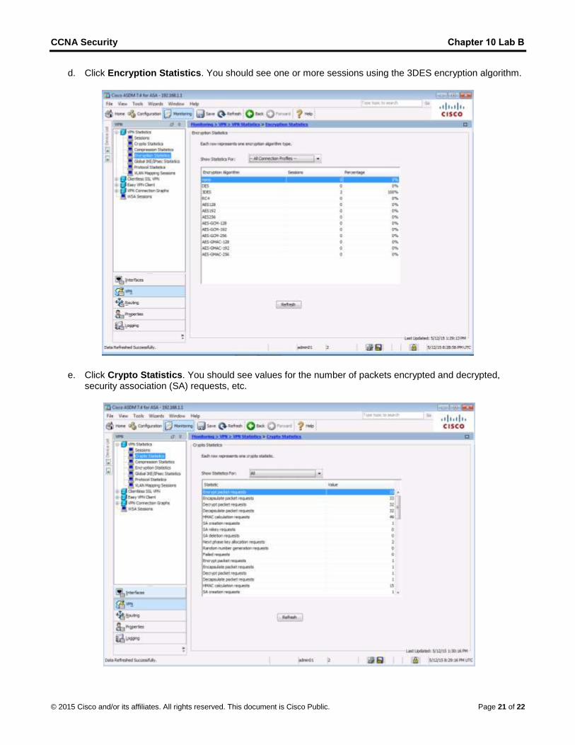
d. Click Encryption Statistics. You should see one or more sessions using the 3DES encryption algorithm.
e. Click Crypto Statistics. You should see values for the number of packets encrypted and decrypted,security association (SA) requests, etc.
CCNA Security Chapter 10 Lab B
© 2015 Cisco and/or its affiliates. All rights reserved. This document is Cisco Public. Page 22 of 22
Reflection
Describe a situation where a site-to-site IPsec VPN would be preferable over other VPN options.
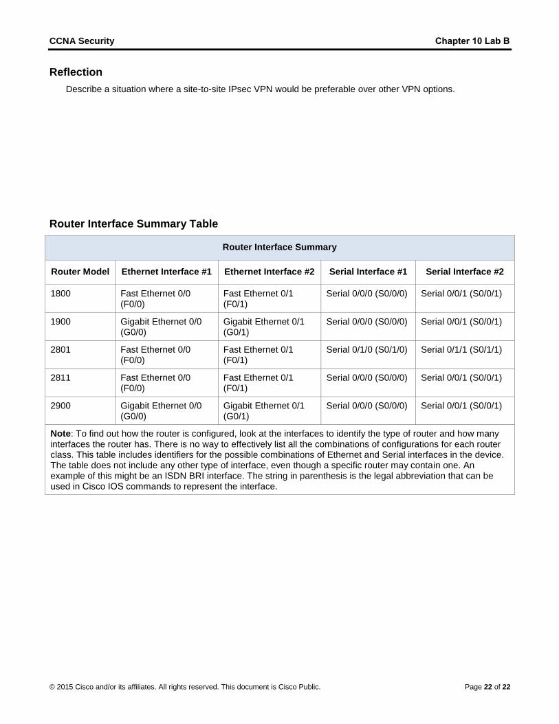
Router Interface Summary Table
Router Interface Summary
Router Model Ethernet Interface #1 Ethernet Interface #2 Serial Interface #1 Serial Interface #2
1800 Fast Ethernet 0/0 (F0/0)
Fast Ethernet 0/1 (F0/1)
Serial 0/0/0 (S0/0/0) Serial 0/0/1 (S0/0/1)
1900 Gigabit Ethernet 0/0 (G0/0)
Gigabit Ethernet 0/1 (G0/1)
Serial 0/0/0 (S0/0/0) Serial 0/0/1 (S0/0/1)
2801 Fast Ethernet 0/0 (F0/0)
Fast Ethernet 0/1 (F0/1)
Serial 0/1/0 (S0/1/0) Serial 0/1/1 (S0/1/1)
2811 Fast Ethernet 0/0 (F0/0)
Fast Ethernet 0/1 (F0/1)
Serial 0/0/0 (S0/0/0) Serial 0/0/1 (S0/0/1)
2900 Gigabit Ethernet 0/0 (G0/0)
Gigabit Ethernet 0/1 (G0/1)
Serial 0/0/0 (S0/0/0) Serial 0/0/1 (S0/0/1)
Note: To find out how the router is configured, look at the interfaces to identify the type of router and how many interfaces the router has. There is no way to effectively list all the combinations of configurations for each router class. This table includes identifiers for the possible combinations of Ethernet and Serial interfaces in the device. The table does not include any other type of interface, even though a specific router may contain one. An example of this might be an ISDN BRI interface. The string in parenthesis is the legal abbreviation that can be used in Cisco IOS commands to represent the interface.