![CURRICULUM VITAE Prof. Dr. Jorge Mateu 1. EDUCATION …mateu/brief-cv-MATEU-sept-2020.pdf · Updated September 2020 CURRICULUM VITAE Prof. Dr. Jorge Mateu 1. EDUCATION-CAREER [1987-92]](https://static.fdocuments.net/doc/165x107/5ff1e57c29b04318e32fd33e/curriculum-vitae-prof-dr-jorge-mateu-1-education-mateubrief-cv-mateu-sept-2020pdf.jpg)
Chapter 10 · PDF fileChapter 10 PDMS Microfluidic Capillary Systems for Patterning Proteins...
18
177 Ali Khademhosseini et al. (eds.), Biological Microarrays: Methods and Protocols, Methods in Molecular Biology, vol. 671, DOI 10.1007/978-1-59745-551-0_10, © Springer Science+Business Media, LLC 2011 Chapter 10 PDMS Microfluidic Capillary Systems for Patterning Proteins on Surfaces and Performing Miniaturized Immunoassays Mateu Pla-Roca and David Juncker Abstract In this chapter, we describe the fabrication and use of microfluidic capillary systems (CSs) made in soft, transparent polydimethylsiloxane (PDMS). Sixteen microfluidic CSs, each containing a loading pad, a microchannel, and a capillary pump are engraved in a single PDMS chip. The CSs are used for two applications, firstly to pattern fibronectin on glass surfaces to locally control the adhesion of cultured cells to the substrate, and secondly to carry out multiplexed miniaturized immunoassays. Key words: Microfluidics, Miniaturizated immunoassays, Micromosaic immunoassays, Protein patterning Microfluidic systems can transport minute amounts on solutions and replace macroscopic tubes, pipettes, vessels, and dishes in a myriad of applications. They help save reagents by reducing sample size from milliliters to microliters, decrease the time to result by enhancing mass transport, and allow many reactions to be carried out simultaneously on a small chip. These characteristics have driven the adoption of microfluidic systems in many different fields and notably in chemistry, biology, and medicine. A microfluidic capillary system (CS) is made of three elements: a loading pad, a microchannel, and a capillary pump, each with a precisely designed geometry. The three elements are structured into a flat substrate, and the recessed (inner) surface is made 1. Introduction 1.1. Microfluidic Capillary Systems
Transcript of Chapter 10 · PDF fileChapter 10 PDMS Microfluidic Capillary Systems for Patterning Proteins...

177
Ali Khademhosseini et al. (eds.), Biological Microarrays: Methods and Protocols, Methods in Molecular Biology, vol. 671,DOI 10.1007/978-1-59745-551-0_10, © Springer Science+Business Media, LLC 2011
Chapter 10
PDMS Microfluidic Capillary Systems for Patterning Proteins on Surfaces and Performing Miniaturized Immunoassays
Mateu Pla-Roca and David Juncker
Abstract
In this chapter, we describe the fabrication and use of microfluidic capillary systems (CSs) made in soft, transparent polydimethylsiloxane (PDMS). Sixteen microfluidic CSs, each containing a loading pad, a microchannel, and a capillary pump are engraved in a single PDMS chip. The CSs are used for two applications, firstly to pattern fibronectin on glass surfaces to locally control the adhesion of cultured cells to the substrate, and secondly to carry out multiplexed miniaturized immunoassays.
Key words: Microfluidics, Miniaturizated immunoassays, Micromosaic immunoassays, Protein patterning
Microfluidic systems can transport minute amounts on solutions and replace macroscopic tubes, pipettes, vessels, and dishes in a myriad of applications. They help save reagents by reducing sample size from milliliters to microliters, decrease the time to result by enhancing mass transport, and allow many reactions to be carried out simultaneously on a small chip. These characteristics have driven the adoption of microfluidic systems in many different fields and notably in chemistry, biology, and medicine.
A microfluidic capillary system (CS) is made of three elements: a loading pad, a microchannel, and a capillary pump, each with a precisely designed geometry. The three elements are structured into a flat substrate, and the recessed (inner) surface is made
1. Introduction
1.1. Microfluidic Capillary Systems
178 Pla-Roca and Juncker
hydrophilic. A liquid delivered to the loading pad of a CS therefore spontaneously fills the microchannel and capillary pump by capillary forces alone. The direction and the flow rate are defined by the capillary forces and the flow resistance, both of which depend on the geometry of the three elements of the CS, and which can therefore be controlled (and preprogrammed) by modifying the geometry. “Capillary systems” and “microfluidic networks” have both been used to describe arrays of microchan-nels that are filled by capillary force and used for immunoassays and surface patterning. In this chapter, we use the word CS to reflect the fact that the microchannels have been designed (via the use of capillary effects) to perform specific microfluidic operations for a particular set of applications.
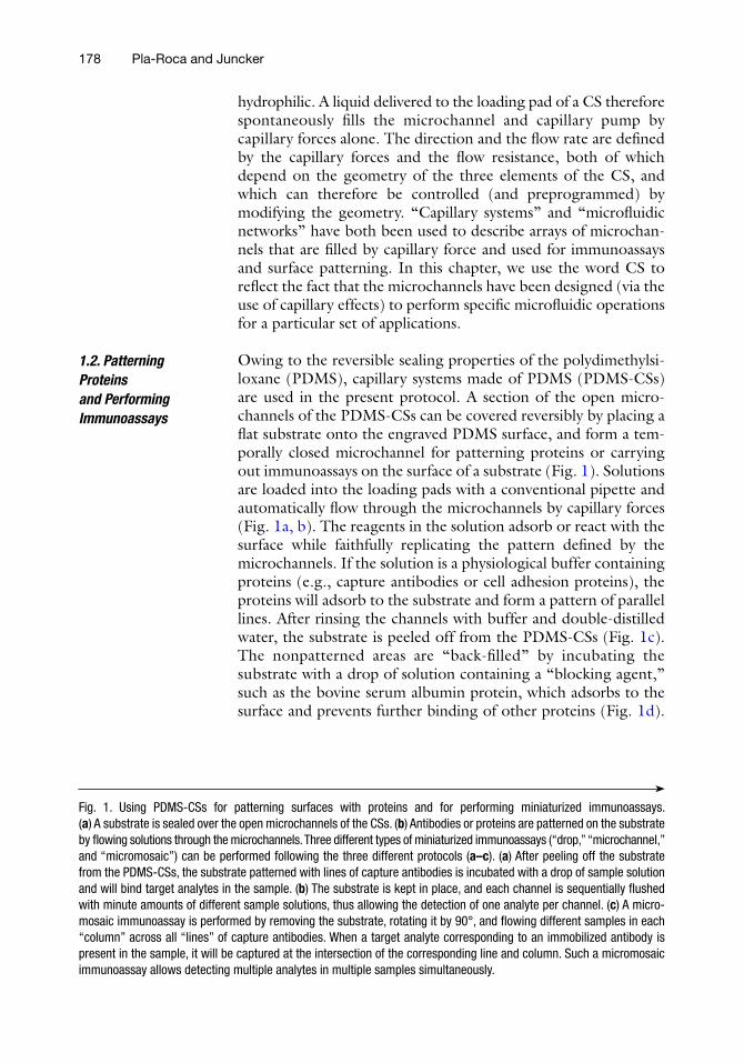
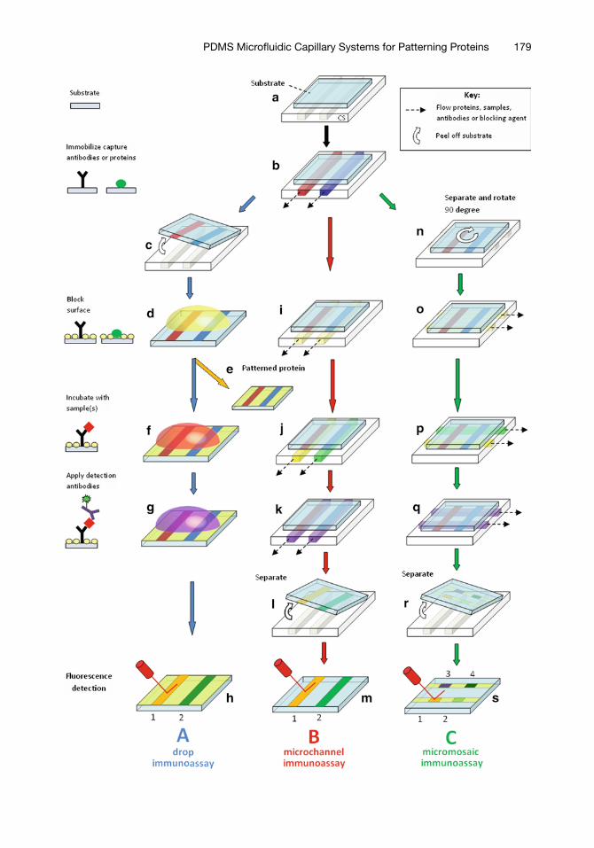
Owing to the reversible sealing properties of the polydimethylsi-loxane (PDMS), capillary systems made of PDMS (PDMS-CSs) are used in the present protocol. A section of the open micro-channels of the PDMS-CSs can be covered reversibly by placing a flat substrate onto the engraved PDMS surface, and form a tem-porally closed microchannel for patterning proteins or carrying out immunoassays on the surface of a substrate (Fig. 1). Solutions are loaded into the loading pads with a conventional pipette and automatically flow through the microchannels by capillary forces (Fig. 1a, b). The reagents in the solution adsorb or react with the surface while faithfully replicating the pattern defined by the microchannels. If the solution is a physiological buffer containing proteins (e.g., capture antibodies or cell adhesion proteins), the proteins will adsorb to the substrate and form a pattern of parallel lines. After rinsing the channels with buffer and double-distilled water, the substrate is peeled off from the PDMS-CSs (Fig. 1c). The nonpatterned areas are “back-filled” by incubating the substrate with a drop of solution containing a “blocking agent,” such as the bovine serum albumin protein, which adsorbs to the surface and prevents further binding of other proteins (Fig. 1d).
1.2. Patterning Proteins and Performing Immunoassays
Fig. 1. Using PDMS-CSs for patterning surfaces with proteins and for performing miniaturized immunoassays. (a) A substrate is sealed over the open microchannels of the CSs. (b) Antibodies or proteins are patterned on the substrate by flowing solutions through the microchannels. Three different types of miniaturized immunoassays (“drop,” “microchannel,” and “micromosaic”) can be performed following the three different protocols (a–c). (a) After peeling off the substrate from the PDMS-CSs, the substrate patterned with lines of capture antibodies is incubated with a drop of sample solution and will bind target analytes in the sample. (b) The substrate is kept in place, and each channel is sequentially flushed with minute amounts of different sample solutions, thus allowing the detection of one analyte per channel. (c) A micro-mosaic immunoassay is performed by removing the substrate, rotating it by 90°, and flowing different samples in each “column” across all “lines” of capture antibodies. When a target analyte corresponding to an immobilized antibody is present in the sample, it will be captured at the intersection of the corresponding line and column. Such a micromosaic immunoassay allows detecting multiple analytes in multiple samples simultaneously.
179PDMS Microfluidic Capillary Systems for Patterning Proteins

180 Pla-Roca and Juncker
The patterned surface can be used for cell cultures (Fig. 1e) if cell adhesion proteins were patterned (1, 2) or for performing immu-noassays if antibodies were patterned. A “drop” immunoassay (Fig. 1a) is performed by incubating the patterned substrate surface with a drop of a sample solution (Fig. 1f). Each line of immobilized capture antibody specifically binds its target analytes in the sample in a concentration-dependent manner. Fluorescent detection antibodies are then delivered over the substrate and bind only to the line where the target analytes have been captured and immobilized (Fig. 1g). The result of the assay is visualized with a fluorescence microarray scanner or a fluorescence micro-scope (Fig. 1h). In one experiment, it is thus possible to detect multiple analytes contained in a small sample (3).
Alternatively, it is possible to perform all the steps of an immunoassay without removing the substrate from the engraved PDMS (Fig. 1b) by sequentially delivering and flowing solu-tions of blocking agent, samples, and labeled detection anti-bodies through the CSs (Fig. 1i–m). We call this approach protocol a “microchannel” immunoassay. Each microchannel corresponds to a single analyte only, and repeated delivery of the sample to multiple channels is necessary to analyze multiple analytes. This protocol further reduces sample consumption and incubation time because a few hundred nanoliters can suffice for tens of minutes of continuous flow and sample replenishment within the microchannels, and thus enable high-sensitivity assays (4, 5).
It is also possible to measure multiple analytes in multiple samples simultaneously by first patterning m) capture antibodies, then removing the substrate, rotating it by 90°, and sealing it against a second microengraved PDMS-CSs (Fig. 1c). The second PDMS-CS is used to flow the blocking agent, (n) different samples and detection antibodies across the capture lines (Fig. 1o–q). In this scenario, each intersection represents a unique combination, and m × n different binding reactions can be performed at once on a single chip. After peeling off the substrate from the CSs (Fig. 1r), the binding is analyzed by fluorescence imaging and each binding event forms a bright square at the intersection (Fig. 1s); because the overall pattern appears as a “mosaic” of squares (Fig. 2), these assays have been dubbed “micromosaic” immunoassays. Such assays have been used to quantify cross-reactivity between antibodies (6), measure DNA hybridization rates (7), detect protein biomarkers (8) (Fig. 2d), viruses, and bacteria analytes (9), and perform com-petitive immunoassays (10).
In the following protocol, we provide some basic design guidelines on how to make and use PDMS-CSs and a step by step description on how to pattern proteins and to carry out the miniaturized immunoassays presented in Fig. 1.

181PDMS Microfluidic Capillary Systems for Patterning Proteins
CSs can be made in silicon (Si), glass, or PDMS. PDMS has spontaneous and reversible sealing properties; therefore,PDMS-CSs are advantageous as they can be sealed to any type of smooth surface. This property allows using glass and gold substrates, coated with silanes and thiols, respectively, or polymer substrates made of polystyrene, polycarbonate, or poly (methylmethacrylate). The glass surfaces used in this protocol are coated with a self-assembled monolayer of a silane with epoxy groups prior to use (11). The epoxy groups on the surface ensure a good attachment of the proteins via a covalent reaction between the epoxy group and their amino groups.
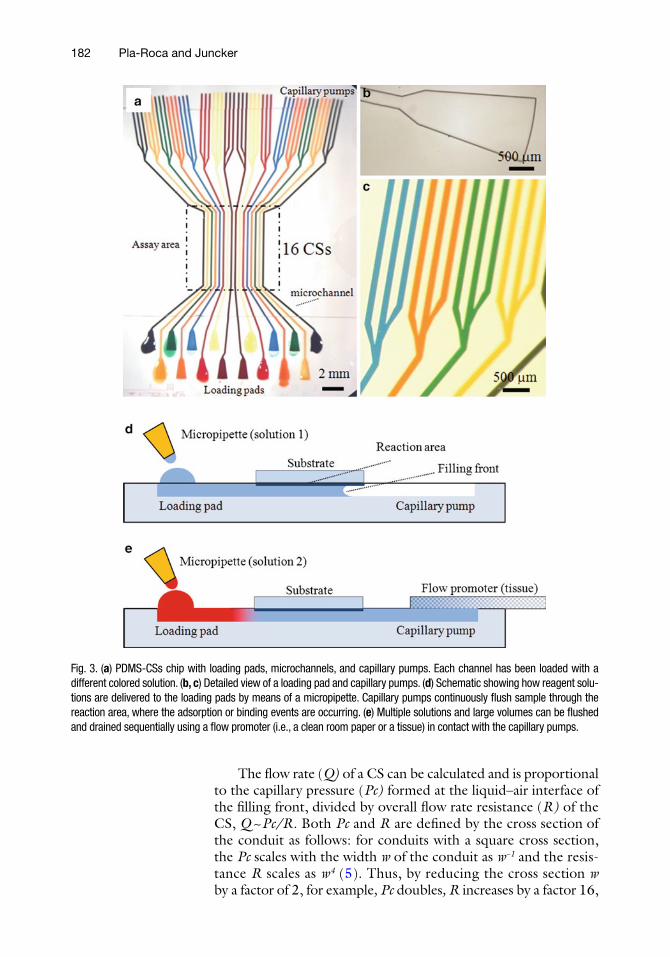
PDMS-CSs are made by replica molding (12) of a master that is typically made of a Si wafer, structured with an inverse pattern of the microchannels. The PDMS-CSs presented here comprise an array of 16 independent CSs, each containing a loading pad, an open microchannel, and a capillary pump (Fig. 3a–c). Once the loading pad is filled with a solution, the negative capillary pressure at the liquid–air interface at the filling front produces a continuous flow, without the need for peripheral pumps, or con-trollers, or connections (Fig. 3d). The key to spontaneous filling is to “activate” the inside surface of the PDMS microchannels and render it hydrophilic, which can be done by exposing the chip to an oxygen plasma or to ozone.
1.3. Designing PDMS-CSs
Fig. 2. Micromosaic immunoassays performed on a PDMS substrate. (a) Fluorescence image of a capture antibody (against goat immunoglobulin) labeled with a green fluorescent dye that was patterned and immobilized as lines. (b) Fluorescence image showing the bound analyte (goat immunoglobulin labeled with a red fluorescent dye), bound at the intersections and forming squares. (c) View of the 16 × 16 intersections of the micromosaic assay. The lanes 8 and 9 were flushed with buffer only and serve as a negative control. The full assay protocol is described in this chapter. (d) Simultaneous detection of the cardiac biomarkers myoglobin (Mb), cardiac Troponin I (cTnI), S100a and C-reactive protein (CRP), and B-type natriuretic peptide (BMP) in human plasma. Four capture antibodies (aMb, acTnI, aS100a, and a CRP) were patterned as horizontal “lines” on a PDMS substrate and used to capture biomarkers spiked into plasma samples (from healthy subjects) delivered in the vertical “columns.” The captured biomarkers were detected by filling the vertical “columns” with a cocktail of fluorescently labeled detection antibodies (reproduced from 8 with permission of Elsevier Science).
182 Pla-Roca and Juncker
The flow rate (Q) of a CS can be calculated and is proportional to the capillary pressure (Pc) formed at the liquid–air interface of the filling front, divided by overall flow rate resistance (R) of the CS, Q ~ Pc/R. Both Pc and R are defined by the cross section of the conduit as follows: for conduits with a square cross section, the Pc scales with the width w of the conduit as w−1 and the resis-tance R scales as w4 (5). Thus, by reducing the cross section w by a factor of 2, for example, Pc doubles, R increases by a factor 16,
Fig. 3. (a) PDMS-CSs chip with loading pads, microchannels, and capillary pumps. Each channel has been loaded with a different colored solution. (b, c) Detailed view of a loading pad and capillary pumps. (d) Schematic showing how reagent solu-tions are delivered to the loading pads by means of a micropipette. Capillary pumps continuously flush sample through the reaction area, where the adsorption or binding events are occurring. (e) Multiple solutions and large volumes can be flushed and drained sequentially using a flow promoter (i.e., a clean room paper or a tissue) in contact with the capillary pumps.

183PDMS Microfluidic Capillary Systems for Patterning Proteins
and Q decreases by a factor of 8. One important parameter that needs to be considered when designing a CS is that as the channel is being filled over an increasing length l, the flow resistance R also continuously increases proportionally to the filled length, R ~ l for a channel with a constant cross section. In addition, the resistance of all upstream sections needs to be added as well. The characteristic dimension of the microstructures in the capillary pumps is made smaller than the one in the loading pad to create a stronger capillary pressure and generate unidirectional flow toward the pump. The arborescent architecture of the capillary pumps provides a high capillary pressure and a large volume while not significantly adding to the overall flow resistance when being filled because all channels run parallel to one another. The capillary pump also serves as a waste or as a sample concentrator. The total volume of each capillary pump is only a few hundred nanoliters, but larger volumes can be loaded in each CS and flowed through each assay area if a tissue (or any kind of wicking material) or evap-oration is used to drain liquid in one or several capillary pumps (Fig. 3e). A capillary retention valve (CRV) can be used as a control element for entirely self-regulated and autonomous CSs. CRVs prevent undesired drainage of the assay area and trapping of bub-bles, and are particularly useful when multiple solutions are added sequentially to many channels, but are beyond the scope of this chapter. Interested readers can find additional information on the design and use of CRVs in 4, 5.
To design a CS, the following parameters need to be taken into account:
1. CS chip. The larger the number of CSs, the more difficult it becomes to load them rapidly without error. The chip shown (Fig. 3a) includes 16 CSs each 30 mm long.
2. Loading pads. The size of the loading pads and the spacing between them have to be sufficiently large in order to allow manual delivery of solutions with a micropipette. In the pre-sented design, the loading pad area is approximately 0.7 mm2.
3. Microchannels. The length (l), width (w), depth (d), and spac-ing (s) are critical parameters to be considered. The assay area is 8 mm long, and each microchannel is 150 mm wide, 30 mm deep, and the channels are arrayed with a pitch of 300 mm. CSs have a high flow rate. For high-sensitivity immunoassays, we recommend 10–30 mm deep channels and aspect ratios between 1:2 and 2:1 (5). The length of the microchannels on the assay area of the CS array should be sufficiently long to allow an easy rotation of the substrate when a “micromosaic” immunoassay is performed.
4. Capillary pumps. A trade-off has to be made between a small pump with a limited capacity and a large pump with a big footprint, which will limit the number of CSs that can be arrayed on a chip.
184 Pla-Roca and Juncker
1. Polystyrene Petri dishes (150 mm × 15 mm and 60 mm × 15 mm, untreated, Corning, MA).
2. Vacuum desiccator and a vacuum line (1 mm Hg). 3. Plasma chamber (Plasma Line 415, Tegal Corporation, CA)
connected to air or oxygen. Alternatively, an ozone produc-tion system can be used.
4. Leveled oven with thermometer. 5. Nitrogen blowgun or duster (ChemTronics, Ultra Jet, GA). 6. Tweezers (SPI, 2A). Round flat tip. 7. Microscope slides (Fisher, 25 cm × 75 cm, precleaned). 8. Powder-free gloves (Fisher). 9. Tape (Scotch Ruban Magic tape). 10. Clean room paper (Perotex 100, Perotech Sciences inc.,
Montreal, Canada). 11. Absorbent paper (Kimwipe, SPI supplies, PA). 12. Nitrogen blowgun or duster (ChemTronics, Ultra Jet, GA). 13. Micropipette (0.5–2 and 100–1,000 mL). 14. Scalpel or cutter. 15. Double-distilled water. 16. 96% ethanol and 75% ethanol.
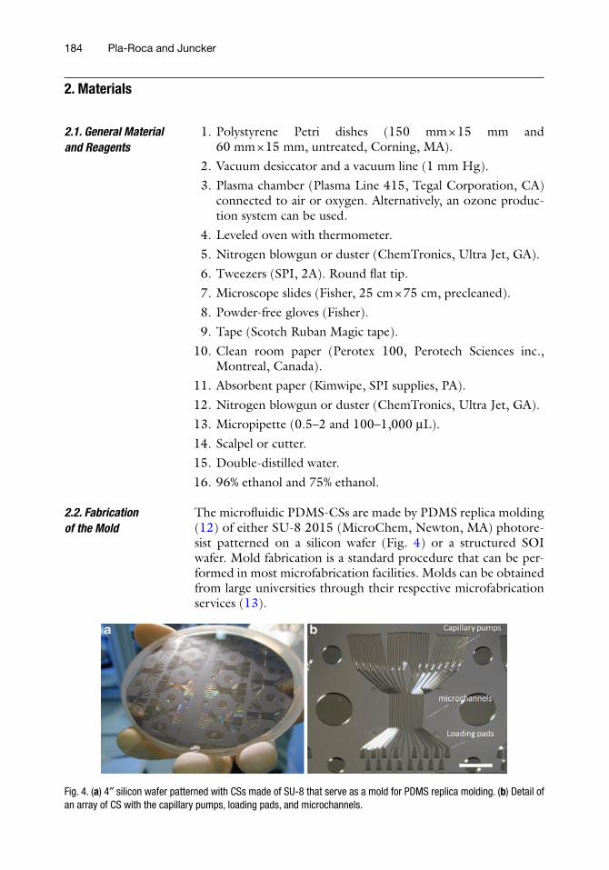
The microfluidic PDMS-CSs are made by PDMS replica molding (12) of either SU-8 2015 (MicroChem, Newton, MA) photore-sist patterned on a silicon wafer (Fig. 4) or a structured SOI wafer. Mold fabrication is a standard procedure that can be per-formed in most microfabrication facilities. Molds can be obtained from large universities through their respective microfabrication services (13).
2. Materials
2.1. General Material and Reagents
2.2. Fabrication of the Mold
Fig. 4. (a) 4″ silicon wafer patterned with CSs made of SU-8 that serve as a mold for PDMS replica molding. (b) Detail of an array of CS with the capillary pumps, loading pads, and microchannels.
185PDMS Microfluidic Capillary Systems for Patterning Proteins
1. Photomask with the design (Fineline Imaging, Colorado Springs, CO) (see Note 1). Patterns have to be clear on the photomask because SU-8 is a negative resist.
2. SU-8 2015 (Microchem, Newton, MA). 3. HMDS, Hexamethyldisilazane (reagent grade 99%, Sigma–
Aldrich). SU-8 adhesion promoter. 4. Spin coater. 5. Photolithographic aligner or collimated UV light source. 6. SU-8 developer (Microchem, Newton, MA). 7. Silicon substrates (4″) (Monto Silicon Technologies). 8. TPFS, Trichloro-1H,1H,2H,2H-perfluorooctylsilane (97%,
Sigma-Aldrich). 9. Digitally controlled hot plate (VWR, 810-HPS). 10. Glass Petri dish (5″).
1. PDMS Sylgard 184 prepolymer (Dow Corning, Midland, MI).
1. Round or rectangular cover slips (Fisher brand). 2. Toluene (97%, Fisher Scientific, ACS reagent). 3. Epoxy silane, 3-Glycidoxypropyldimethoxymethylsilane
(3-GPS, 97%, Sigma-Aldrich). 4. Cover slip staining racks (two units) and staining dishes (two
units) (Fisher Scientific).
1. Phosphate buffered saline (PBS) (Fisher Bioreagents, 1X, pH 7.4) and double-distilled water filtered with syringe filters (FisherBrand, 0.22 mm, 13 mm syringe PVDF sterile).
2. Carbonate–bicarbonate buffer, pH 9.6, prepared following manufacturer’s instructions (Carbonate–bicarbonate buffer capsule, Sigma-Aldrich). Filter the buffer with a syringe filter after preparation.
3. Capture antibody solution: Chicken antigoat immunoglobu-lin labeled with Alexa Fluor 488 dye (AF488, green fluores-cence) from Invitrogen diluted at 100 mg/mL with PBS. Store at 2–8°C and protect from light. Bring to room tempera-ture before using it.
4. Blocking solution: 1% (w/v) bovine serum albumin (BSA) (Sigma-Aldrich) in filtered PBS (Fisher Bioreagents, 1X, pH 7.4).
5. Assay buffer: 0.1% (w/v) BSA (Sigma-Aldrich) and 0.1% (w/v) Tween-20 (Sigma-Aldrich) in PBS.
2.3. Molding of PDMS-CSs and Flat PDMS Substrate
2.4. Coating of Cover Slips with an Epoxy Silane
2.5. Reagents, Proteins, and Antibody Solutions
186 Pla-Roca and Juncker
6. Sample solution: Goat immunoglobulin labeled with Alexa Fluor 647 dye (AF647, red fluorescence) from Invitrogen is diluted at 0.1 mg/mL with assay buffer. Store at 2–8°C and protect from light. Bring to room temperature before using it.
7. Fibronectin solution: Sterile cell culture-tested fibronectin (Sigma-Aldrich) is diluted at 100 mg/mL with carbonate–bicarbonate buffer. No BSA should be added. Store at 2–8 C and bring to room temperature before using it.
1. PDMS microfluidic capillary systems (PDMS-CSs). 2. Epoxy silane-coated cover slips. 3. PBS, fibronectin solution, and blocking solution. The solu-
tions should be used at room temperature. 4. Dulbecco’s Modified Eagle Media (DMEM) and fetal bovine
serum (sterile filtered and cell culture tested) both from Sigma-Aldrich.
5. 4% (w/v) Paraformaldehyde (95% powder, Sigma-Aldrich) solution in PBS.
6. Toluene (97%, Fisher scientific, ACS reagent). 7. Myoblast cells suspension at 1 × 10⁶ cells/mL (C2C12 cell
line, American Type Culture Collection, VA). 8. Microscope with differential interference contrast (DIC) or
phase contrast.
1. PDMS-CSs. 2. Microscope slide (Fisher, 22 cm × 75 cm, precleaned). 3. Square PDMS substrate cut to size (~1 cm2). 4. Blocking, capture antibody, and sample solutions. The solu-
tions should be used at room temperature. 5. Fluorescence scanner with 488 and 633 nm laser excitations
and FITC and Cy5 dyes emission filters or fluorescence microscope with the corresponding filters.
1. Activate the surface of the CSs mold in a plasma chamber for 1 min (see Note 2). Place the activated mold immediately in a desiccator, together with a few drops of TPFS on a cover slip. Connect to vacuum for 1–5 min, close the desiccator valve, and keep the mold for 1 h in the silane atmosphere. The TPFS coating will prevent PDMS from sticking to the mold during replica molding.
2.6. Patterning of Fibronectin on Epoxy-Coated Cover Slips for Cell Culture Applications
2.7. Miniaturized Immunoassay
3. Methods
3.1. Fabrication of PDMS-CSs and Substrates
3.1.1. Fabrication of PDMS-CSs
187PDMS Microfluidic Capillary Systems for Patterning Proteins
2. Transfer the coated mold into a glass Petri dish and place it in an oven at 110°C for 10 min. This will ensure the complete reaction of the silane with the surface.
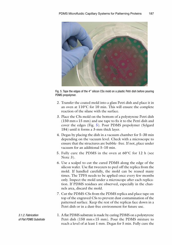
3. Place the CSs mold on the bottom of a polystyrene Petri dish (150 mm × 15 mm) and use tape to fix it to the Petri dish and cover the edges (Fig. 5). Pour PDMS prepolymer (Sylgard 184) until it forms a 3-mm thick layer.
4. Degas by placing the dish in a vacuum chamber for 5–30 min depending on the vacuum level. Check with a microscope to ensure that the structures are bubble- free. If not, place under vacuum for an additional 5–10 min.
5. Fully cure the PDMS in the oven at 60°C for 12 h (see Note 3).
6. Use a scalpel to cut the cured PDMS along the edge of the silicon wafer. Use flat tweezers to peel off the replica from the mold. If handled carefully, the mold can be reused many times. The TPFS needs to be applied once every few months only. Inspect the mold under a microscope after each replica-tion. If PDMS residues are observed, especially in the chan-nels area, discard the mold.
7. Cut the PDMS-CSs from the PDMS replica and place tape on top of the engraved CSs to prevent dust contamination of the patterned surface. Keep the rest of the replicas face down in a Petri dish or in a dust-free environment for future use.
1. A flat PDMS substrate is made by curing PDMS on a polystyrene Petri dish (150 mm × 15 mm). Pour the PDMS mixture to reach a level of at least 1 mm. Degas for 5 min. Fully cure the
3.1.2. Fabrication of Flat PDMS Substrate
Fig. 5. Tape the edges of the 4″ silicon CSs mold on a plastic Petri dish before pouring PDMS prepolymer.

188 Pla-Roca and Juncker
PDMS in the oven at 60°C for 3–12 h and cut out a PDMS block with the desired size. The surface of PDMS cured in contact with the Petri dish is used as assay surface.
1. Fill a staining dish with 99 mL of toluene and cover it with its lid.
2. Place cover slips on the staining rack and plasma treat for 1 min in order to activate the glass surface.
3. Add 1 mL of 3-Glycidoxypropyldimethoxymethylsilane (3-GPS) to the toluene and mix it well. Immediately immerse the activated cover slips for 20 min.
4. Rinse the cover slips with fresh toluene and blow dry with nitrogen (30 s). Place the cover slips on a new staining rack and cure in the oven for 30 min at 110°C.
5. Rinse with ethanol, blow dry, and keep in a dust-free environ-ment for future use.
Fibronectin is a well-characterized multifunctional extracellular matrix protein that mediates cell adhesion, migration, and plays an important role in many cell–surface interactions and wound healing. Fibronectin-coated surfaces promote cell attachment.
To maintain sterility, the following steps should be performed in a cell culture environment or in a biosafety cabinet. Tweezers should be sterilized under a flame or by immersion in a 75% ethanol solution before using them.
1. Use a scalpel to cut out several 2 cm × 5 cm pieces of clean room paper.
2. Use gloves in order to manipulate the PDMS-CSs. Rinse the gloves with ethanol before using them. Peel off the protecting tape from the PDMS-CSs. Rinse the microstructures with ethanol and dry them with nitrogen (1 min).
3. Place the cleaned PDMS-CSs on a glass slide, with the micro-structures facing up. This will allow better handling of the PDMS-CSs during the following steps. Place the PDMS-CSs in the plasma chamber for 1 min in order to render the PDMS-CSs hydrophilic (see Note 4). Stamp the activated PDMS-CSs several times against a flat PDMS surface. This treatment will neutralize the reactive groups on the surface of the CS but will keep the inside of microchannels hydrophilic. This step is important to prevent solution delivered to the loading pads from spreading over the surface, and generally helps minimize leakage and ensure proper function of the CS (e.g., spontaneous filling).
4. Place an epoxy-coated cover slip over the hydrophilized PDMS-CSs. Make sure not to block the loading pads with the cover slip. With a glass scribe, mark a small R (for Rear) near the edge of the cover slip to mark the back side. Slightly
3.1.3. Coating of Cover Slips with Epoxy Silanes
3.2. Patterning Fibronectin on Cover Slips for Cell Culture Applications
189PDMS Microfluidic Capillary Systems for Patterning Proteins
press with the tweezers in order to ensure conformal contact with the PDMS-CSs. Sterilize the setup for a few minutes under UV light and place it in a polystyrene Petri dish (150 mm × 15 mm) along with a wet tissue or paper. This will prevent evaporation during incubation.
5. Load 2 mL of fibronectin solution in the channels, cover the Petri dish with its lid, and incubate for 30 min (see Note 5). Shorter incubation times will result in lower levels of protein attached on the surface.
6. Place the short side of the clean room paper piece (2 cm × 5 cm) over the capillary pumps until all channels are drained. Slightly humidify the paper edge prior to use in order to ensure a better contact with the capillary pumps.
7. Rinse with PBS (3 × 2 mL) and peel off the cover slip. Replace the clean room paper whenever it is saturated.
8. Peel off the PDMS-CSs and place the patterned cover slip with the fibronectin lines facing up in a small Petri dish. Use the previously inscribed small “R” as an orientation mark. Incubate for 2 h at 4°C in order to ensure fibronectin adhe-sion to the surface. Rinse the cover slip with PBS (2 × 2 mL) and add 2 mL of blocking solution. Ensure that the cover slip is perfectly immersed. Incubate for 1 h at room temperature. Remove the blocking solution and rinse several times with filtered PBS (see Note 6).
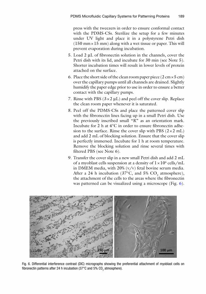
9. Transfer the cover slip in a new small Petri dish and add 2 mL of a myoblast cells suspension at a density of 1 × 10⁶ cells/mL in DMEM media, with 20% (v/v) fetal bovine serum media. After a 24 h incubation (37°C, and 5% CO2 atmosphere), the attachment of the cells to the areas where the fibronectin was patterned can be visualized using a microscope (Fig. 6).
Fig. 6. Differential interference contrast (DIC) micrographs showing the preferential attachment of myoblast cells on fibronectin patterns after 24 h incubation (37°C and 5% CO2 atmosphere).

190 Pla-Roca and Juncker
For imaging purposes, the cells can be fixed by adding 2 mL of 4% (w/v) paraformaldehyde PBS solution to the Petri dish for 10 min at 37°C. Rinse the cover slips with PBS (3 × 2 mL) and double-distilled water (1 × 2 mL) .
1. Use a scalpel to cut several (2 cm × 5 cm) pieces of clean room paper.
2. Use a scalpel to cut a 1 cm2 piece of PDMS substrate. Before peeling it off from the Petri dish, make a notch in one of the corners. This notch will help proper alignment of the sub-strate in later procedures (see Note 7). Using the tweezers, peel off the substrate, pulling from the edges in order to avoid tearing of the PDMS. Place the PDMS substrate in a Petri dish in order to protect it from dust.
3. Peel off the tape that protects the PDMS-CSs from dust, rinse the microstructures with ethanol, and dry them under a stream of nitrogen for several seconds. Use powder-free gloves to manipulate the PDMS-CSs.
4. Place the cleaned PDMS-CSs chip in a microscope glass slide, with the microstructures facing up. Place the PDMS-CSs in a plasma chamber for 1 min in order to hydrophilize the sur-face (see Note 4). Bring the hydrophilized PDMS-CSs several times into contact with a flat PDMS surface. This treatment will minimize leakages and facilitate the loading of solutions on the microchannels.
5. Place the PDMS substrate on top of the PDMS-CSs channels. Press slightly in order to ensure conformal contact. Make sure not to block the loading pads with the substrate. (Fig. 7a). Place the microscope slide with the immunoassay setup sur-rounded by a wet tissue or paper in a polystyrene Petri dish (150 mm × 15 mm). This will prevent evaporation during incubation procedures.
6. Load 2 mL of PBS buffer in microchannels 8 and 9 as negative controls. Load all other microchannels with 2 mL of capture antibody solutions (chicken antigoat immunoglobulin labeled with AF488 has been used in the present protocol for dem-onstration purposes) (Fig. 7a). Cover the Petri dish with its lid in order to prevent evaporation, and incubate antibodies for 1 min.
7. Place the short side of the clean room paper (2 cm × 5 cm) over the capillary pumps until all channels are drained (Fig. 7b). Do not let dry for an extended time (see Note 8).
Any of the three miniaturized immunoassay variants can be performed at this stage (Fig. 1a–c, see Subheading 1). The pro-tocol for the “drop” immunoassay (Fig. 1, protocol A) follows the same steps as for the “microchannel” (Fig. 1, protocol B)
3.3. Miniaturized Immunoassays

191PDMS Microfluidic Capillary Systems for Patterning Proteins
and the “micromosaic” immunoassay (Fig. 1, protocol C) which are described below, but, with the exception that whenever fill-ing of the microchannels is described, a drop of solution is to be applied to the patterned PDMS surface instead. This drop fur-ther needs to be spread over the entire surface of the substrate using a glass cover slip, and incubated for ten times longer than the time indicated for steps carried out in a microfluidic channel.
8. Remove the wet clean room paper and load the channels with 2 mL of BSA blocking solution. Incubate for 1 min. Unload the channels with a new piece of clean room paper and keep it in place.
9. Rinse the channels (3 × 2 mL) with PBS and (1 × 2 mL) with double-distilled water. Replace the clean room paper if saturated.
10. (C only) Peel off the PDMS substrate and blow it dry with the nitrogen blowgun (10 s). Use the tweezers for this pro-cess. Rotate the PDMS substrate by 90° and place it over a new PDMS-CS previously activated in the plasma chamber. Use the notch for orientation (Fig. 7c).
11. (C only) Load the channels with 2 mL of BSA blocking solu-tion. Incubate for 1 min. Unload the channels with a new piece of clean room paper.
12. Load 2 mL of sample solution into each CS and incubate for 3 min (see Note 9). Drain the channels with clean room paper. The incubation time will be dependent on the binding capacity of the capture antibodies used and the analyte con-centration to be detected. The longer the incubation, the higher the sensitivity.
In the present protocol, a solution containing goat immunoglob-ulin AF 647 was used as the sample, and the corresponding result is shown in Fig. 2a. For a full micromosaic immunoassay as the one shown in Fig. 2b, steps 13 and 14 need to be carried
Fig. 7. (a) Loaded CSs with capture antibody solution. A PDMS substrate with a notch has been placed on the assay area. (b) Draining capture antibody solution by means of the clean room paper placed over the capillary pumps. (c) Microchannels loaded with sample solutions. The notch on the PDMS substrate is used as orientation in the course of the 90º substrate rotation. For visualization purposes, color dye has been added to the loaded solutions. Scale bar 2 mm.

192 Pla-Roca and Juncker
out to deliver the labeled detection antibodies that will bind to the immobilized analyte.
13. Rinse the microchannels (3 × 2 mL) with PBS. Replace the clean room paper whenever it is saturated.
14. Load the microchannels with the corresponding fluorescently labeled detection antibodies in assay buffer and incubate them for 20 min. The recommended concentration is 1 mg/mL (see Note 10).
15. Rinse the microchannels (3 × 2 mL) with PBS and (1 × 2 mL) double-distilled water. Use a clean room paper in order to drain each solution.
16. Peel off the PDMS substrate and dry it under a stream of nitrogen (30 s). The immunoassay result is revealed by imag-ing with a fluorescence microscope or scanner (see Note 11). The result of the demonstration mosaic immunoassay is shown in Fig. 2a (see Subheading 1).
1. The design of the photomask can be made using Inkscape (open source software), CorelDraw (Corel Corporation) or Adobe Illustrator (Adobe systems), or more specialized soft-ware such as Clewin 4.0 (Vieweb, Netherlands) or Autodesk (AutoCAD, Autodesk). The photomask can be made of mylar foil or glass depending on the requirements of the photo-lithographic process (i.e., aligner).
2. Plasma will clean the mold surface and activate it for func-tionalization. Time and power vary depending on the plasma chamber used, and the processing time should be kept short to prevent heating and damaging of the SU-8 features on the mold. Alternatively, an ozone chamber (Ozomax Corporation, http://www.ozomax.com) can be used for activation, but the processing time will need to be increased.
3. Curing of PDMS can be accelerated by using a higher tem-perature up to 90°C. At 90°C, curing takes only 1 h, but shrinkage of PDMS becomes more pronounced and most of the Petri dishes melt at 70°C.
4. PDMS surfaces after plasma treatment remain activated (and hydrophilic) only a few minutes because uncured low-molecular weight PDMS migrates from the bulk to the air–surface interface.
5. Proteins attach covalently to epoxy-coated slides due to the reaction between the protein lysine residues with the 3-GPS epoxy groups at basic pH.
4. Notes

193PDMS Microfluidic Capillary Systems for Patterning Proteins
6. In the present protocol, BSA has been used as the blocking agent in order to reduce the attachment of the cells on the areas where fibronectin is not present. Alternatively, Pluronic® F127 (Ethylene Oxide/Propylene Oxide Block Copolymer, BASF) can also be used to reduce the attachment of the cells (14).
7. Use tape to remove residual PDMS debris. This is a really effective method to clean the PDMS surface.
8. More advanced CSs with a CRV can be designed in order to prevent the drying of the microchannels on the assay area (4).
9. Incubation time of the samples will depend on the concentra-tion of the analytes to be detected and the affinity of the capture antibodies used. An incubation time of 12 min with continuous flow driven by evaporation was used in order to detect tumor necrosis factor a (TNF-a) )at a concentration of 20 pg/mL in cell culture media (15).
10. If the signal is too weak, the concentration can be varied, although problems due to nonspecific adsorptions of detec-tion antibodies over the substrate may increase as well.
11. When using a fluorescence microarray scanner, we recom-mended sticking the substrate to a microscope slide or a cover slip, with the assay substrate surface stuck to the glass to facili-tate focusing and manipulation of the sample. This necessi-tates a scanner that can scan through the glass (e.g., LS Reload Tecan Laser Scanner or Agilent Technologies DNA microar-ray Scanner).
Acknowledgments
The authors would like to thank Emmanuel Delamarche and Ute Drechsler (IBM Research Center, Zurich) for the fabrication of the molds. We are also very grateful to Saravanan Sundararajan and Haig Djambazian (Genome Quebec, McGill University, Montreal) for providing the myoblast cells and the DIC micros-copy imaging of the cells. M. P. acknowledges financial support of the Spanish Ministry of Science postdoctoral fellows.
References
1. Lang, S., von Philipsborn A. C., Bernard, A., Bonhoeffer, F., Bastmeyer, M. (2008) Growth cone response to ephrin gradients produced by microfluidic networks. Anal. Bioanal. Chem. 390, 3, 809–816.
2. Jiang, X., Xu Q., Dertinger, S. K. W., Stroock A. D., Fu, T., Whitesides G. M. A. (2005) General method for patterning gradients of biomolecules on surfaces
using microfluidic networks. Anal. Chem. 77, 2338–2347.
3. Delamarche, E., Bernard, A. (1997) Patterned delivery of immunoglobulins to surfaces using microfluidic networks. Science 276, 779–781.
4. Juncker, D., Schmid H., Drechsler, U, Wolf, H., Wolf, M., Michel, B., Nico de Rooij, Delamarche, E. (2002) Autonomous microfluidic capillary system. Anal. Chem. 74, 6139–6144.

194 Pla-Roca and Juncker
5. Delamarche, E., Juncker, D., Schmid, H. (2005) Microfluidics for processing surfaces and miniaturizing biological assays. Adv. Mater. 17, 2911–2933.
6. Bernard, A., Michel, B., Delamarche, E. (2001) Micromosaic immunoassays. Anal. Chem. 73, 8–12.
7. Benn J. A., Hu, J., Hogan B. J., Fry R. C., Samson L. D., Thorsen T. (2006) Comparative modeling and analysis of microfluidic and conventional DNA microarrays. Anal. Biochem. 348, 284–293.
8. Wolf, M., Juncker, D., Michel, B., Hunziker, P., Delamarche, E. (2004) Simultaneous detection of C-reactive protein and other car-diac markers in human plasma using micro-mosaic immunoassays and self-regulating microfluidic networks. Biosens. Bioelectron. 19, 1193–1202.
9. Rowe, C. A., Tender, L. M., Feldstein, M. J., et al. (1999) Array biosensor for simultaneous identification of bacterial, viral, and protein analytes. Anal. Chem. 71, 3846–3852.
10. Murphy, B. M., He, X., Dandy, D., Henry, C. S. (2008) Competitive immunoassays for
simultaneous detection of metabolites and proteins using micromosaic patterning. Anal. Chem. 80, 444–450.
11. Nam, Y., Branch, D. W., Wheeler, B. C. (2006) Epoxy-silane linking of biomole-cules is simple and effective for patterning neuronal cultures. Biosens. Bioelectron. 22, 589–597.
12. Younan, X., Whitesides, G. M. (1998) Soft lithography. Angew. Chem. Int. Ed. 37, 550–575.
13. http://people.seas.harvard.edu/~jones/lab_arch/nano_facilities/nano_facilities.html, http://microlab.berkeley.edu/, http://snf.stanford.edu/
14. Tan, J. L., Liu, W., Nelson, C. M., Raghavan, S., Chen, C. S. (2004) Simple approach to micropattern cells on common culture sub-strates by tuning substrate wettability. Tissue Eng. 10, 865–872.
15. Cesaro-Tadic, S., Dernick, G., Juncker, D., et al. (2004) High-sensitivity miniaturized immunoassays for tumor necrosis factor alpha using microfluidic systems. Lab on a Chip. 4, 563–569.