Chapter 1 Spinner Propeller - Cudacountry · SOLIDWORKS 15 PROPELLER SPINNER PagE 1-1 Spinner...
46
SOLIDWORKS 15 PROPELLER SPINNER P AGE 1-1 Spinner Propeller A. Extruded Boss/Base. Step 1. Click File Menu > New, click Part and OK. Step 2. Click Top Plane in the Feature Manager and click Sketch on the Context toolbar, Fig. 1. Step 3. Click Circle (S) on the Sketch toolbar. Step 4. Draw a circle starting at the Origin , Fig. 2. Step 5. Click Smart Dimension (S) on the Sketch toolbar. Step 6. Dimension diameter .4, Fig. 2. Step 7. Click Features on the Command Manager toolbar. Step 8. Click Extruded Boss/Base on the Features toolbar. Step 9. In the Property Manager set: under Direction 1, Fig. 3 Depth .625 click OK . Step 10. Click Zoom to Fit (F) on the View toolbar. B. Save as "PROPELLER". Step 1. Click File Menu > Save As. Step 2. Key-in PROPELLER for the filename and press ENTER. Chapter 1 12/3/14 Origin Fig. 3 Fig. 4 Fig. 2 Fig. 1 © Cudacountry.net Tech Ed http://www.cudacountry.net email:[email protected]
Transcript of Chapter 1 Spinner Propeller - Cudacountry · SOLIDWORKS 15 PROPELLER SPINNER PagE 1-1 Spinner...
SOLIDWORKS 15 PROPELLER SPINNER PagE 1-1
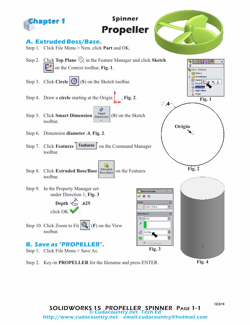
Spinner
Propeller A. Extruded Boss/Base.Step 1. Click File Menu > New, click Part and OK.
Step 2. Click Top Plane in the Feature Manager and click Sketch on the Context toolbar, Fig. 1.
Step 3. Click Circle (S) on the Sketch toolbar.
Step 4. Draw a circle starting at the Origin , Fig. 2.
Step 5. Click Smart Dimension (S) on the Sketch toolbar.
Step 6. Dimension diameter .4, Fig. 2.
Step 7. Click Features on the Command Manager toolbar.
Step 8. Click Extruded Boss/Base on the Features toolbar.
Step 9. In the Property Manager set: under Direction 1, Fig. 3
Depth .625
click OK .
Step 10. Click Zoom to Fit (F) on the View toolbar.
B. Save as "PROPELLER".Step 1. Click File Menu > Save As.
Step 2. Key-in PROPELLER for the filename and press ENTER.
Chapter 1
12/3/14
Origin
Fig. 3
Fig. 4
Fig. 2
Fig. 1
© Cudacountry.net Tech Edhttp://www.cudacountry.net email:[email protected]
SOLIDWORKS 15 PROPELLER SPINNER PagE 1-2
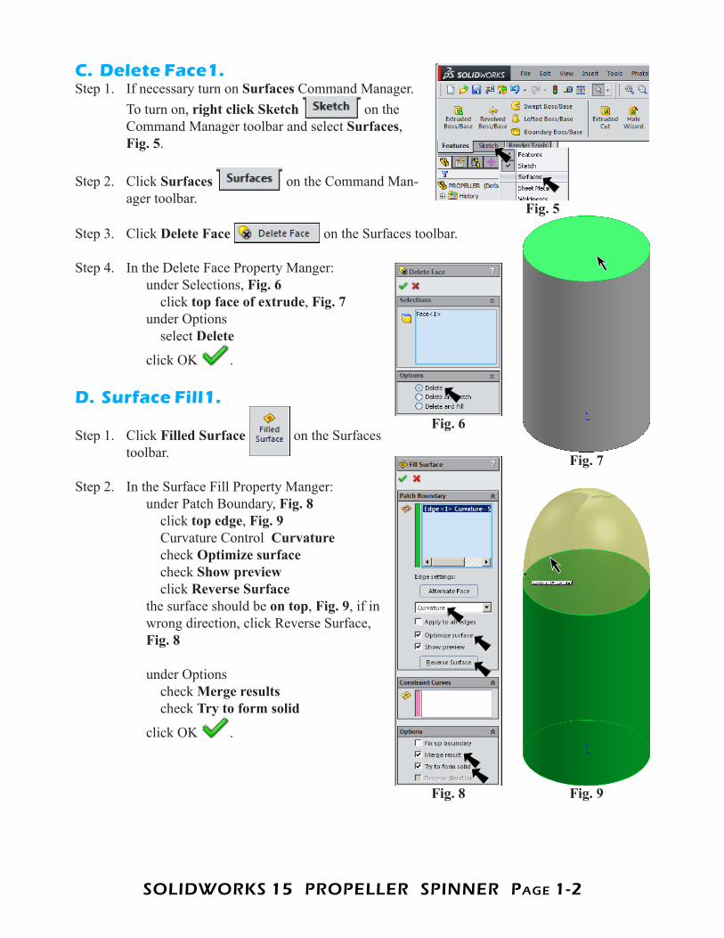
C. Delete Face1.Step 1. If necessary turn on Surfaces Command Manager.
To turn on, right click Sketch on the Command Manager toolbar and select Surfaces, Fig. 5.
Step 2. Click Surfaces on the Command Man-ager toolbar.
Step 3. Click Delete Face on the Surfaces toolbar.
Step 4. In the Delete Face Property Manger: under Selections, Fig. 6 click top face of extrude, Fig. 7 under Options select Delete
click OK .
D. Surface Fill1.
Step 1. Click Filled Surface on the Surfaces toolbar.
Step 2. In the Surface Fill Property Manger: under Patch Boundary, Fig. 8 click top edge, Fig. 9 Curvature Control Curvature check Optimize surface check Show preview click Reverse Surface the surface should be on top, Fig. 9, if in wrong direction, click Reverse Surface, Fig. 8 under Options check Merge results check Try to form solid
click OK .
Fig. 5
Fig. 6
Fig. 7
Fig. 8 Fig. 9
SOLIDWORKS 15 PROPELLER SPINNER PagE 1-3
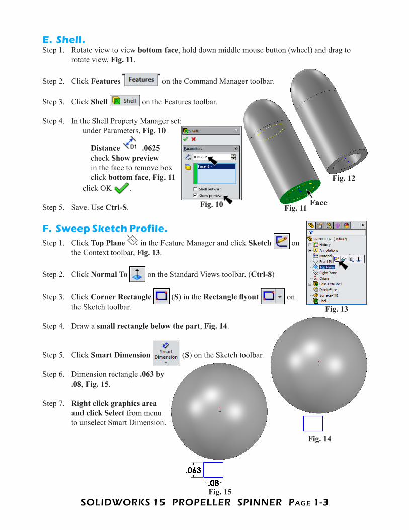
E. Shell.Step 1. Rotate view to view bottom face, hold down middle mouse button (wheel) and drag to
rotate view, Fig. 11.
Step 2. Click Features on the Command Manager toolbar.
Step 3. Click Shell on the Features toolbar.
Step 4. In the Shell Property Manager set: under Parameters, Fig. 10
Distance .0625 check Show preview in the face to remove box click bottom face, Fig. 11 click OK .
Step 5. Save. Use Ctrl-S.
F. Sweep Sketch Profile.Step 1. Click Top Plane in the Feature Manager and click Sketch on
the Context toolbar, Fig. 13.
Step 2. Click Normal To on the Standard Views toolbar. (Ctrl-8)
Step 3. Click Corner Rectangle (S) in the Rectangle flyout on the Sketch toolbar.
Step 4. Draw a small rectangle below the part, Fig. 14.
Step 5. Click Smart Dimension (S) on the Sketch toolbar.
Step 6. Dimension rectangle .063 by .08, Fig. 15.
Step 7. Right click graphics area and click Select from menu to unselect Smart Dimension.
Fig. 10 Fig. 11
Fig. 12
Fig. 13
Fig. 14
Fig. 15
Face
SOLIDWORKS 15 PROPELLER SPINNER PagE 1-4
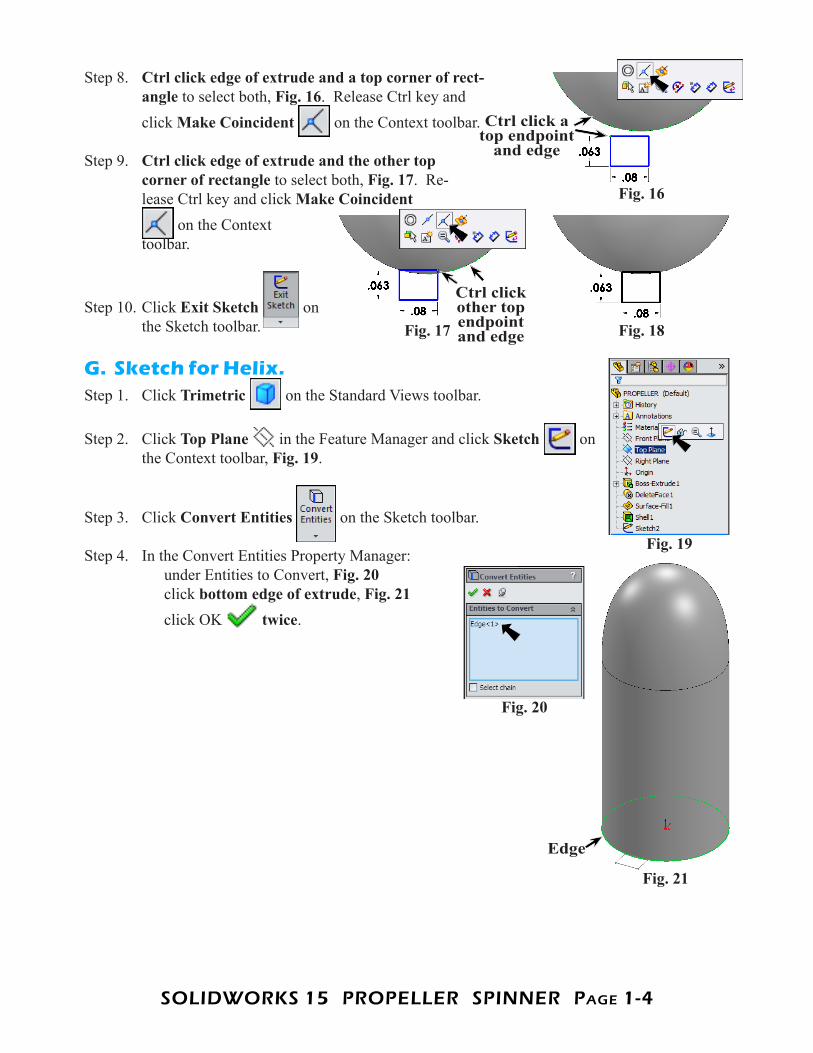
Step 8. Ctrl click edge of extrude and a top corner of rect-angle to select both, Fig. 16. Release Ctrl key and click Make Coincident on the Context toolbar.
Step 9. Ctrl click edge of extrude and the other top corner of rectangle to select both, Fig. 17. Re-lease Ctrl key and click Make Coincident
on the Context toolbar.
Step 10. Click Exit Sketch on the Sketch toolbar.
G. Sketch for Helix.Step 1. Click Trimetric on the Standard Views toolbar.
Step 2. Click Top Plane in the Feature Manager and click Sketch on the Context toolbar, Fig. 19.
Step 3. Click Convert Entities on the Sketch toolbar.
Step 4. In the Convert Entities Property Manager: under Entities to Convert, Fig. 20 click bottom edge of extrude, Fig. 21 click OK twice.
Fig. 16
Ctrl click a top endpoint
and edge
Fig. 17
Ctrl click other top endpoint and edge Fig. 18
Fig. 19
Fig. 20
Fig. 21
Edge
SOLIDWORKS 15 PROPELLER SPINNER PagE 1-5
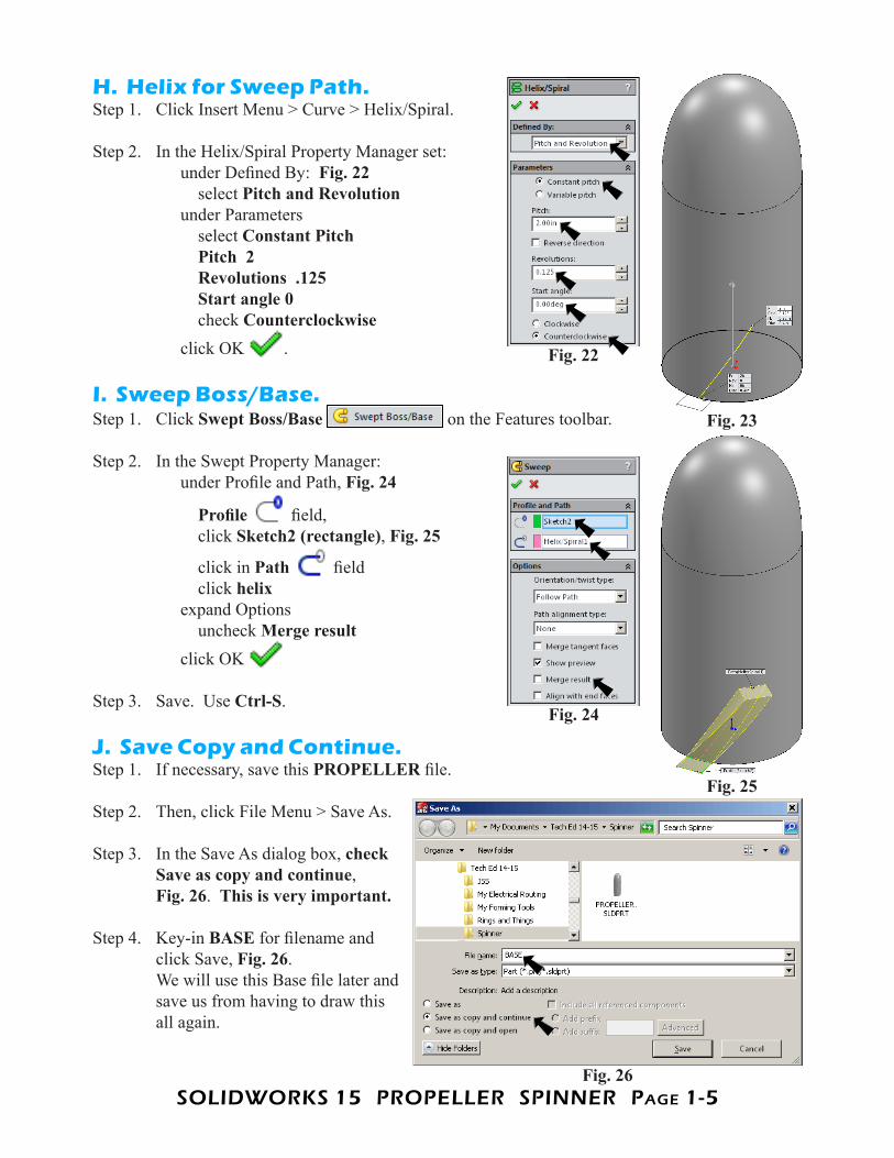
H. Helix for Sweep Path.Step 1. Click Insert Menu > Curve > Helix/Spiral.
Step 2. In the Helix/Spiral Property Manager set: under Defined By: Fig. 22 select Pitch and Revolution under Parameters select Constant Pitch Pitch 2 Revolutions .125 Start angle 0 check Counterclockwise click OK .
I. Sweep Boss/Base.Step 1. Click Swept Boss/Base on the Features toolbar.
Step 2. In the Swept Property Manager: under Profile and Path, Fig. 24
Profile field, click Sketch2 (rectangle), Fig. 25
click in Path field click helix expand Options uncheck Merge result click OK
Step 3. Save. Use Ctrl-S.
J. Save Copy and Continue.Step 1. If necessary, save this PROPELLER file.
Step 2. Then, click File Menu > Save As.
Step 3. In the Save As dialog box, check Save as copy and continue,Fig. 26. This is very important.
Step 4. Key-in BASE for filename and click Save, Fig. 26.We will use this Base file later and save us from having to draw this all again.
Fig. 22
Fig. 23
Fig. 24
Fig. 25
Fig. 26
SOLIDWORKS 15 PROPELLER SPINNER PagE 1-6
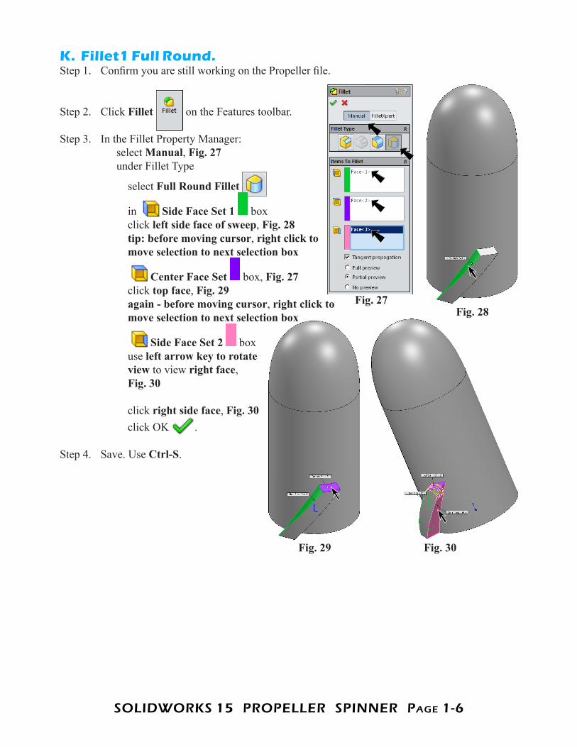
K. Fillet1 Full Round.Step 1. Confirm you are still working on the Propeller file.
Step 2. Click Fillet on the Features toolbar.
Step 3. In the Fillet Property Manager: select Manual, Fig. 27 under Fillet Type
select Full Round Fillet
in Side Face Set 1 box click left side face of sweep, Fig. 28 tip: before moving cursor, right click to move selection to next selection box
Center Face Set box, Fig. 27 click top face, Fig. 29 again - before moving cursor, right click to move selection to next selection box
Side Face Set 2 box use left arrow key to rotate view to view right face, Fig. 30
click right side face, Fig. 30 click OK .
Step 4. Save. Use Ctrl-S.
Fig. 27Fig. 28
Fig. 30Fig. 29
SOLIDWORKS 15 PROPELLER SPINNER PagE 1-7
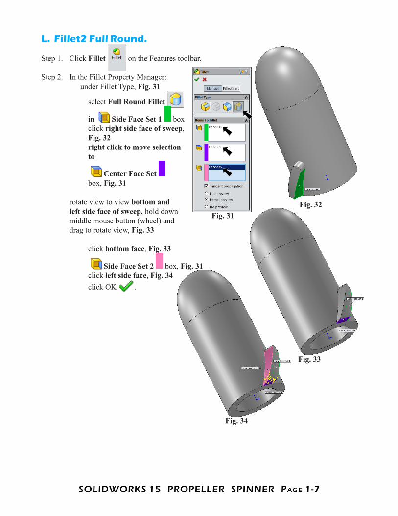
L. Fillet2 Full Round.
Step 1. Click Fillet on the Features toolbar.
Step 2. In the Fillet Property Manager: under Fillet Type, Fig. 31
select Full Round Fillet
in Side Face Set 1 box click right side face of sweep, Fig. 32 right click to move selection to
Center Face Set box, Fig. 31 rotate view to view bottom and left side face of sweep, hold down middle mouse button (wheel) and drag to rotate view, Fig. 33
click bottom face, Fig. 33
Side Face Set 2 box, Fig. 31 click left side face, Fig. 34 click OK .
Fig. 31Fig. 32
Fig. 33
Fig. 34
SOLIDWORKS 15 PROPELLER SPINNER PagE 1-8
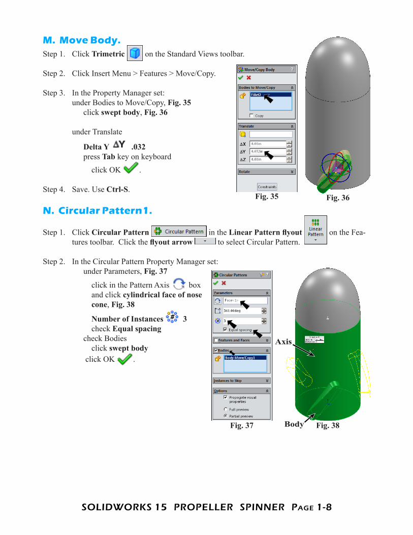
M. Move Body.Step 1. Click Trimetric on the Standard Views toolbar.
Step 2. Click Insert Menu > Features > Move/Copy.
Step 3. In the Property Manager set: under Bodies to Move/Copy, Fig. 35 click swept body, Fig. 36 under Translate
Delta Y .032 press Tab key on keyboard click OK .
Step 4. Save. Use Ctrl-S.
N. Circular Pattern1.
Step 1. Click Circular Pattern in the Linear Pattern flyout on the Fea-tures toolbar. Click the flyout arrow to select Circular Pattern.
Step 2. In the Circular Pattern Property Manager set: under Parameters, Fig. 37
click in the Pattern Axis box and click cylindrical face of nose cone, Fig. 38
Number of Instances 3 check Equal spacing check Bodies click swept body click OK .
Fig. 35 Fig. 36
Fig. 37 Fig. 38
Axis
Body
SOLIDWORKS 15 PROPELLER SPINNER PagE 1-9
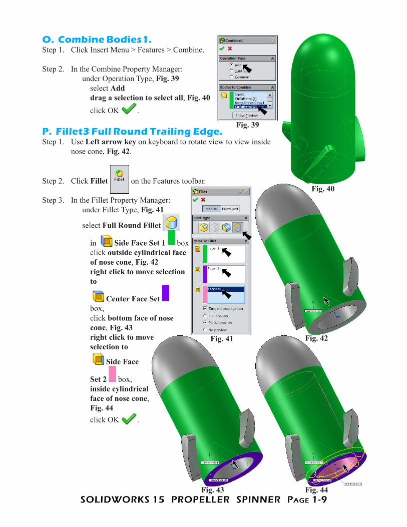
O. Combine Bodies1.Step 1. Click Insert Menu > Features > Combine.
Step 2. In the Combine Property Manager: under Operation Type, Fig. 39 select Add drag a selection to select all, Fig. 40 click OK .
P. Fillet3 Full Round Trailing Edge.Step 1. Use Left arrow key on keyboard to rotate view to view inside
nose cone, Fig. 42.
Step 2. Click Fillet on the Features toolbar.
Step 3. In the Fillet Property Manager: under Fillet Type, Fig. 41
select Full Round Fillet
in Side Face Set 1 box click outside cylindrical face of nose cone, Fig. 42 right click to move selection to
Center Face Set box, click bottom face of nose cone, Fig. 43 right click to move selection to
Side Face
Set 2 box, inside cylindrical face of nose cone, Fig. 44 click OK .
Fig. 39
Fig. 40
Fig. 41 Fig. 42
Fig. 44Fig. 43

SOLIDWORKS 15 PROPELLER SPINNER PagE 1-10
Q. Fillet4 Sweep Edges.
Step 1. Click Fillet on the Features toolbar.
Step 2. In the Fillet Property Manager, under Fillet Type, Fig. 45
select Constant Size Fillet under Fillet Parameters
Radius .02 select Full preview under Items To Fillet click an edge of sweep, Fig. 46
click All, 27 Edges on the Fillet pop-up toolbar, Fig. 47 click OK .
Step 3. Save. Use Ctrl-S.Fig. 45
Fig. 46
Fig. 49
Fig. 48Fig. 47
SOLIDWORKS 15 PROPELLER SPINNER PagE 1-11
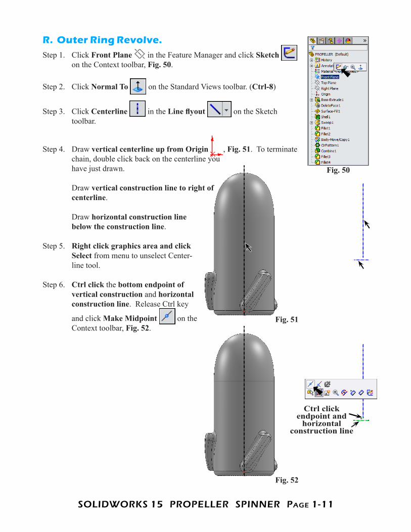
R. Outer Ring Revolve.Step 1. Click Front Plane in the Feature Manager and click Sketch
on the Context toolbar, Fig. 50.
Step 2. Click Normal To on the Standard Views toolbar. (Ctrl-8)
Step 3. Click Centerline in the Line flyout on the Sketch toolbar.
Step 4. Draw vertical centerline up from Origin , Fig. 51. To terminate chain, double click back on the centerline you have just drawn. Draw vertical construction line to right of centerline. Draw horizontal construction line below the construction line.
Step 5. Right click graphics area and click Select from menu to unselect Center-line tool.
Step 6. Ctrl click the bottom endpoint of vertical construction and horizontal construction line. Release Ctrl key
and click Make Midpoint on the Context toolbar, Fig. 52.
Fig. 50
Fig. 51
Fig. 52
Ctrl click endpoint and
horizontal construction line
SOLIDWORKS 15 PROPELLER SPINNER PagE 1-12
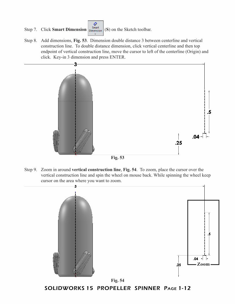
Step 7. Click Smart Dimension (S) on the Sketch toolbar.
Step 8. Add dimensions, Fig. 53. Dimension double distance 3 between centerline and vertical construction line. To double distance dimension, click vertical centerline and then top endpoint of vertical construction line, move the cursor to left of the centerline (Origin) and click. Key-in 3 dimension and press ENTER.
Step 9. Zoom in around vertical construction line, Fig. 54. To zoom, place the cursor over the vertical construction line and spin the wheel on mouse back. While spinning the wheel keep cursor on the area where you want to zoom.
Fig. 53
Fig. 54
Zoom

SOLIDWORKS 15 PROPELLER SPINNER PagE 1-13
Step 10. Click Centerpoint Arc
in the Arc flyout on the Sketch toolbar.
Step 11. Draw centerpoint arc at end of vertical construc-tion line across horizontal construction line, Fig. 55. To draw arc, click bottom endpoint of vertical con-struction line, Position 1 to start arc centerpoint. Click left endpoint of horizon-tal construction line, Position 2 to place first arc endpoint. Then move cursor counter-clockwise to Position 3 on construction line and click to place second arc endpoint.
Step 12. Click Style Spline in the Spline
flyout on the Sketch toolbar.
Step 13. Draw a 6 control vertex point Spline, Fig. 56. Start at left endpoint of arc for 1st control vertex point. Then, draw 2nd control vertex point directly above to create a vertical tangent relations
. Continue and draw the control vertex point as shown in Fig. 56. Press Escape to end spline.
Step 14. Ctrl click top endpoint of centerline and Style Spline to select both, Fig. 57. Release Ctrl key and click Make Coin-cident on the Context toolbar.
Step 15. Click top control polygon segment
and click Make Horizontal on the Context toolbar, Fig. 58.
Step 16. Ctrl click top endpoint of centerline and control vertex points 2 and 5 to select all three,
Fig. 59. Release Ctrl key and click Make Horizontal on the Context toolbar.
Fig. 56Fig. 55
1
2 31
2
3 4
6
5
Fig. 58
Fig. 57
Ctrl click spline and top
endpoint of centerline
Fig. 59
Ctrl click control vertex
points 2 and 5 and top endpoint of
centerline
2 5
SOLIDWORKS 15 PROPELLER SPINNER PagE 1-14
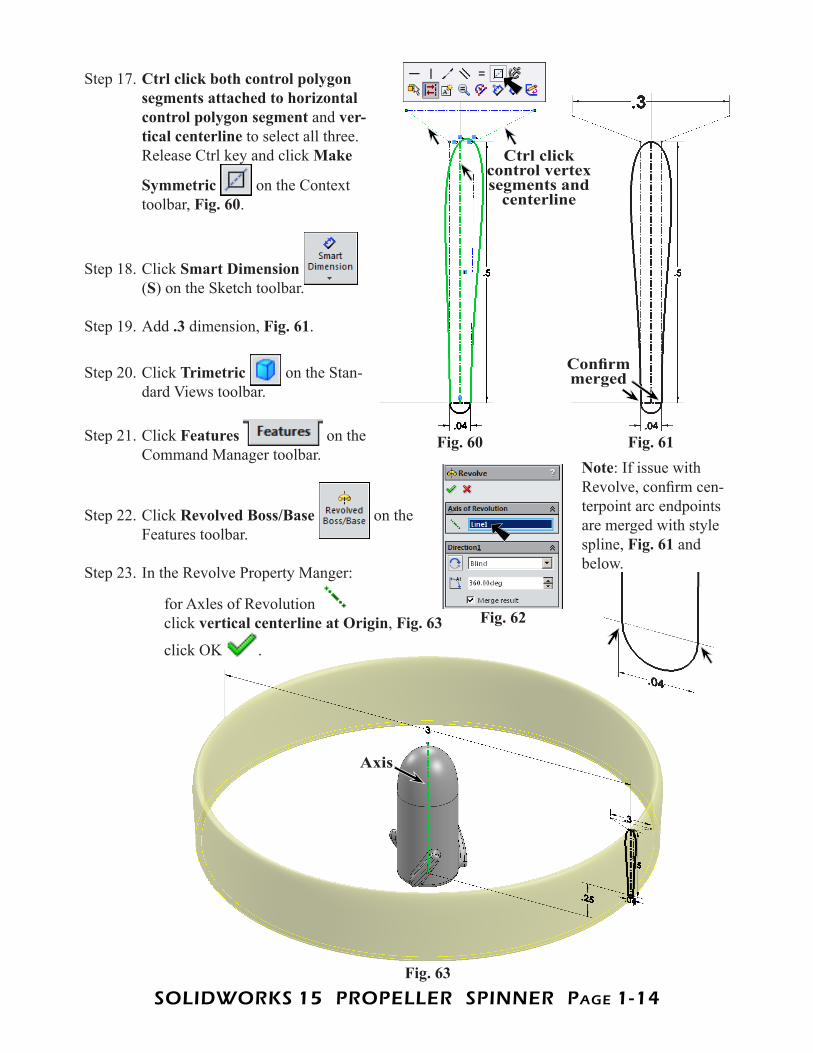
Step 17. Ctrl click both control polygon segments attached to horizontal control polygon segment and ver-tical centerline to select all three. Release Ctrl key and click Make
Symmetric on the Context toolbar, Fig. 60.
Step 18. Click Smart Dimension (S) on the Sketch toolbar.
Step 19. Add .3 dimension, Fig. 61.
Step 20. Click Trimetric on the Stan-dard Views toolbar.
Step 21. Click Features on the Command Manager toolbar.
Step 22. Click Revolved Boss/Base on the Features toolbar.
Step 23. In the Revolve Property Manger:
for Axles of Revolution click vertical centerline at Origin, Fig. 63
click OK .
Fig. 60 Fig. 61
Ctrl click control vertex segments and
centerline
Fig. 62
Fig. 63
Axis
Note: If issue with Revolve, confirm cen-terpoint arc endpoints are merged with style spline, Fig. 61 and below.
Confirm merged
SOLIDWORKS 15 PROPELLER SPINNER PagE 1-15
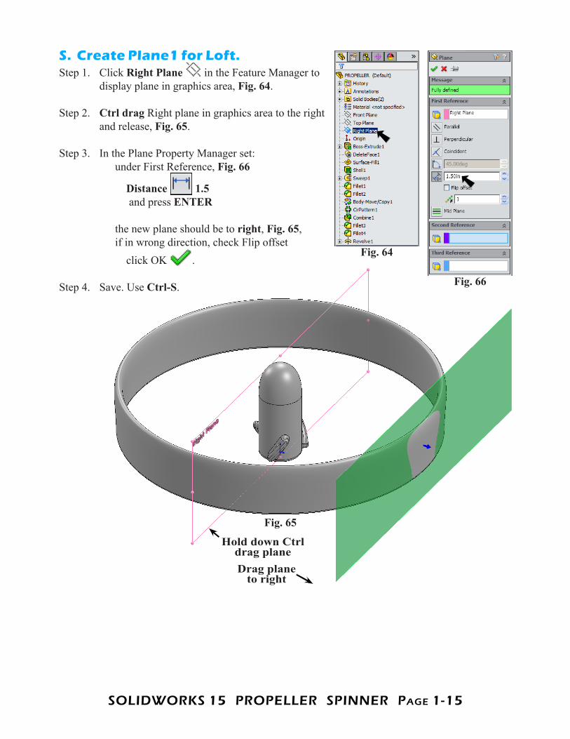
S. Create Plane1 for Loft.Step 1. Click Right Plane in the Feature Manager to
display plane in graphics area, Fig. 64.
Step 2. Ctrl drag Right plane in graphics area to the right and release, Fig. 65.
Step 3. In the Plane Property Manager set: under First Reference, Fig. 66
Distance 1.5 and press ENTER the new plane should be to right, Fig. 65, if in wrong direction, check Flip offset click OK .
Step 4. Save. Use Ctrl-S.
Fig. 64
Fig. 66
Fig. 65
Hold down Ctrl drag plane Drag plane
to right
SOLIDWORKS 15 PROPELLER SPINNER PagE 1-16
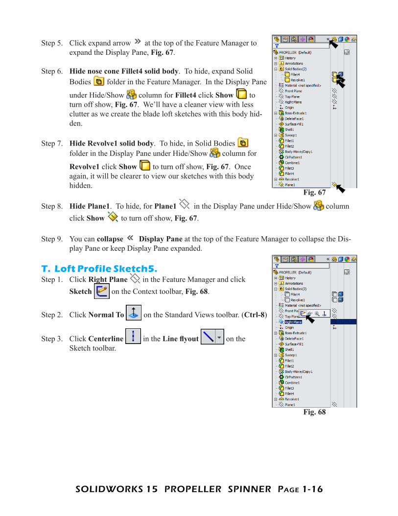
Step 5. Click expand arrow at the top of the Feature Manager to expand the Display Pane, Fig. 67.
Step 6. Hide nose cone Fillet4 solid body. To hide, expand Solid Bodies folder in the Feature Manager. In the Display Pane
under Hide/Show column for Fillet4 click Show to turn off show, Fig. 67. We’ll have a cleaner view with less clutter as we create the blade loft sketches with this body hid-den.
Step 7. Hide Revolve1 solid body. To hide, in Solid Bodies folder in the Display Pane under Hide/Show column for
Revolve1 click Show to turn off show, Fig. 67. Once again, it will be clearer to view our sketches with this body hidden.
Step 8. Hide Plane1. To hide, for Plane1 in the Display Pane under Hide/Show column click Show to turn off show, Fig. 67.
Step 9. You can collapse Display Pane at the top of the Feature Manager to collapse the Dis-play Pane or keep Display Pane expanded.
T. Loft Profile Sketch5.Step 1. Click Right Plane in the Feature Manager and click
Sketch on the Context toolbar, Fig. 68.
Step 2. Click Normal To on the Standard Views toolbar. (Ctrl-8)
Step 3. Click Centerline in the Line flyout on the Sketch toolbar.
Fig. 67
Fig. 68
SOLIDWORKS 15 PROPELLER SPINNER PagE 1-17
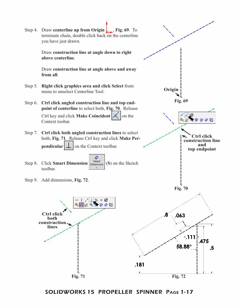
Step 4. Draw centerline up from Origin , Fig. 69. To terminate chain, double click back on the centerline you have just drawn. Draw construction line at angle down to right above centerline. Draw construction line at angle above and away from all.
Step 5. Right click graphics area and click Select from menu to unselect Centerline Tool.
Step 6. Ctrl click angled construction line and top end-point of centerline to select both, Fig. 70. Release Ctrl key and click Make Coincident on the Context toobar.
Step 7. Ctrl click both angled construction lines to select both, Fig. 71. Release Ctrl key and click Make Per-
pendicular on the Context toolbar.
Step 8. Click Smart Dimension (S) on the Sketch toolbar.
Step 9. Add dimensions, Fig. 72.
Fig. 69
Origin
Fig. 70
Fig. 71 Fig. 72
Ctrl click construction line
and top endpoint
Ctrl click both
construction lines
SOLIDWORKS 15 PROPELLER SPINNER PagE 1-18
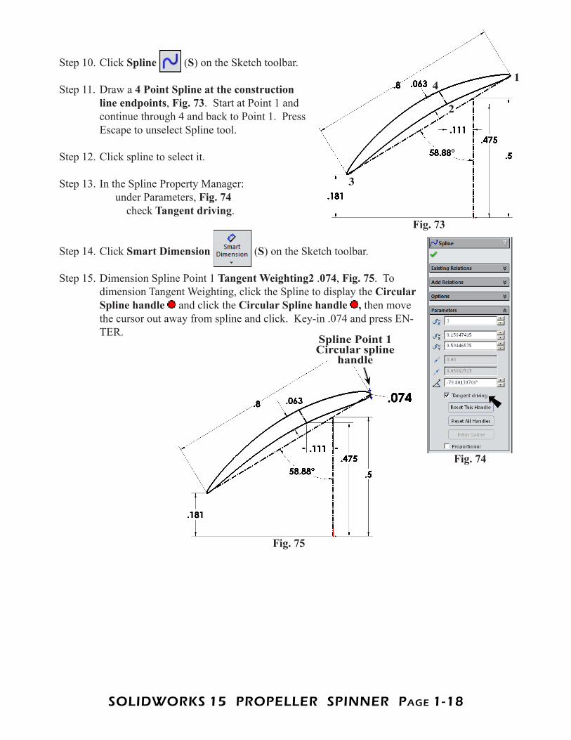
Step 10. Click Spline (S) on the Sketch toolbar.
Step 11. Draw a 4 Point Spline at the construction line endpoints, Fig. 73. Start at Point 1 and continue through 4 and back to Point 1. Press Escape to unselect Spline tool.
Step 12. Click spline to select it.
Step 13. In the Spline Property Manager: under Parameters, Fig. 74 check Tangent driving.
Step 14. Click Smart Dimension (S) on the Sketch toolbar.
Step 15. Dimension Spline Point 1 Tangent Weighting2 .074, Fig. 75. To dimension Tangent Weighting, click the Spline to display the Circular Spline handle and click the Circular Spline handle , then move the cursor out away from spline and click. Key-in .074 and press EN-TER.
Fig. 73
1
2
3
4
Fig. 74
Fig. 75
Spline Point 1 Circular spline
handle
SOLIDWORKS 15 PROPELLER SPINNER PagE 1-19
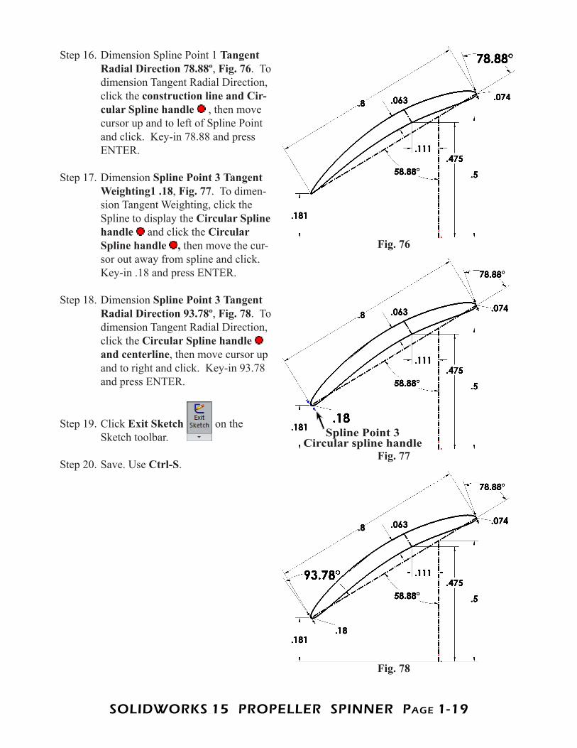
Step 16. Dimension Spline Point 1 Tangent Radial Direction 78.88º, Fig. 76. To dimension Tangent Radial Direction, click the construction line and Cir-cular Spline handle , then move cursor up and to left of Spline Point and click. Key-in 78.88 and press ENTER.
Step 17. Dimension Spline Point 3 Tangent Weighting1 .18, Fig. 77. To dimen-sion Tangent Weighting, click the Spline to display the Circular Spline handle and click the Circular Spline handle , then move the cur-sor out away from spline and click. Key-in .18 and press ENTER.
Step 18. Dimension Spline Point 3 Tangent Radial Direction 93.78º, Fig. 78. To dimension Tangent Radial Direction, click the Circular Spline handle and centerline, then move cursor up and to right and click. Key-in 93.78 and press ENTER.
Step 19. Click Exit Sketch on the Sketch toolbar.
Step 20. Save. Use Ctrl-S.
Fig. 76
Fig. 77
Fig. 78
Spline Point 3 Circular spline handle
SOLIDWORKS 15 PROPELLER SPINNER PagE 1-20
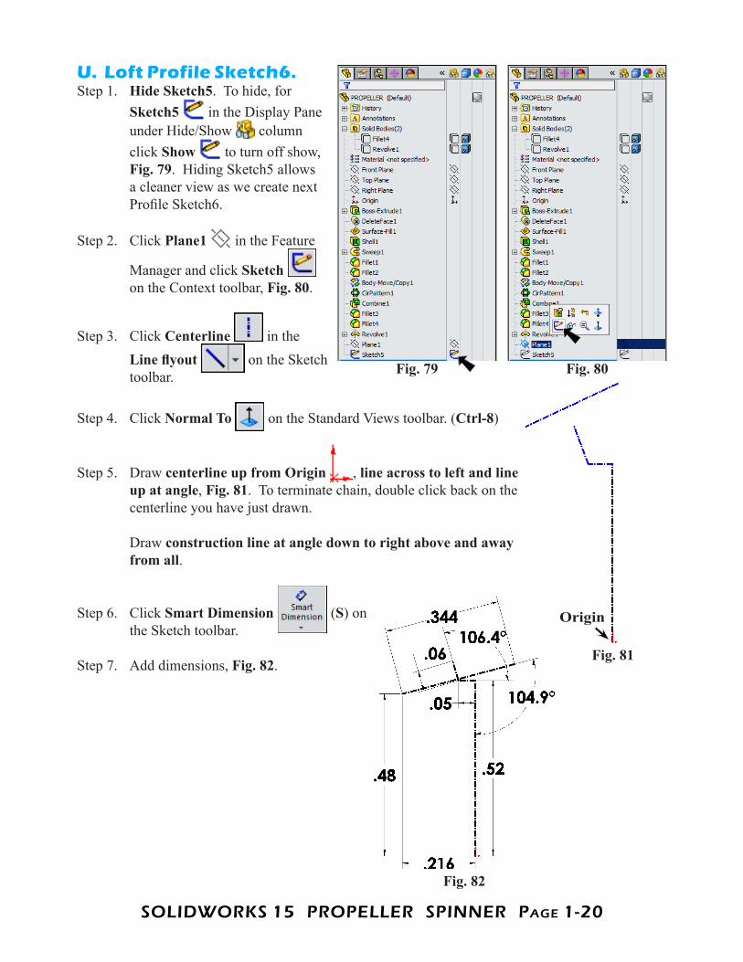
U. Loft Profile Sketch6.Step 1. Hide Sketch5. To hide, for
Sketch5 in the Display Pane under Hide/Show column click Show to turn off show, Fig. 79. Hiding Sketch5 allows a cleaner view as we create next Profile Sketch6.
Step 2. Click Plane1 in the Feature
Manager and click Sketch on the Context toolbar, Fig. 80.
Step 3. Click Centerline in the Line flyout on the Sketch toolbar.
Step 4. Click Normal To on the Standard Views toolbar. (Ctrl-8)
Step 5. Draw centerline up from Origin , line across to left and line up at angle, Fig. 81. To terminate chain, double click back on the centerline you have just drawn. Draw construction line at angle down to right above and away from all.
Step 6. Click Smart Dimension (S) onthe Sketch toolbar.
Step 7. Add dimensions, Fig. 82.
Fig. 80Fig. 79
Fig. 81
Fig. 82
Origin

SOLIDWORKS 15 PROPELLER SPINNER PagE 1-21
Step 8. Click Spline (S) on the Sketch toolbar.
Step 9. Draw a 4 Point Spline at the con-struction line endpoints, Fig. 83. Start at Point 1 and continue through 4 and back to Point 1. Press Escape to unselect Spline tool.
Step 10. Click spline to select it.
Step 11. In the Spline Property Manager: under Parameters check Tangent driving, Fig. 84.
Step 12. Click Smart Dimension (S) on the Sketch toolbar.
Step 13. Dimension Spline Point 1 Tangent Weighting2 .096, Fig. 85. To dimension Tangent Weighting, click the Spline to display the Circular Spline handle and click the Circular Spline handle , then move the cursor out away from spline and click. Key-in .096 and press EN-TER.
Step 14. Dimension Spline Point 1 Tangent Radial Direction 102º, Fig. 86. To dimension Tangent Radial Direction, click the Circular Spline handle and centerline, then move cursor up and to right of Spline Point and click. Key-in 102 and press ENTER.
Fig. 83 Fig. 84
1
2 3
4
Fig. 85
Fig. 86
SOLIDWORKS 15 PROPELLER SPINNER PagE 1-22
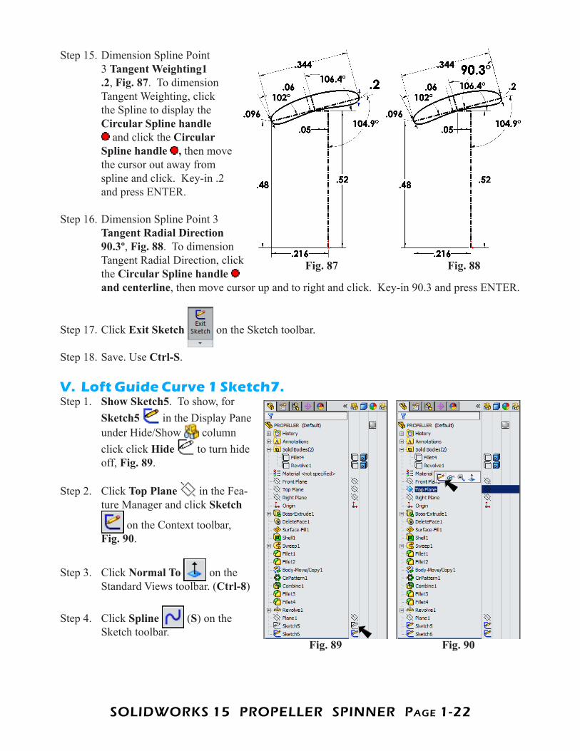
Step 15. Dimension Spline Point 3 Tangent Weighting1 .2, Fig. 87. To dimension Tangent Weighting, click the Spline to display the Circular Spline handle
and click the Circular Spline handle , then move the cursor out away from spline and click. Key-in .2 and press ENTER.
Step 16. Dimension Spline Point 3 Tangent Radial Direction 90.3º, Fig. 88. To dimension Tangent Radial Direction, click the Circular Spline handle and centerline, then move cursor up and to right and click. Key-in 90.3 and press ENTER.
Step 17. Click Exit Sketch on the Sketch toolbar.
Step 18. Save. Use Ctrl-S.
V. Loft Guide Curve 1 Sketch7.Step 1. Show Sketch5. To show, for
Sketch5 in the Display Pane under Hide/Show column click click Hide to turn hide off, Fig. 89.
Step 2. Click Top Plane in the Fea-ture Manager and click Sketch
on the Context toolbar,Fig. 90.
Step 3. Click Normal To on the Standard Views toolbar. (Ctrl-8)
Step 4. Click Spline (S) on the Sketch toolbar.
Fig. 88Fig. 87
Fig. 90Fig. 89
SOLIDWORKS 15 PROPELLER SPINNER PagE 1-23
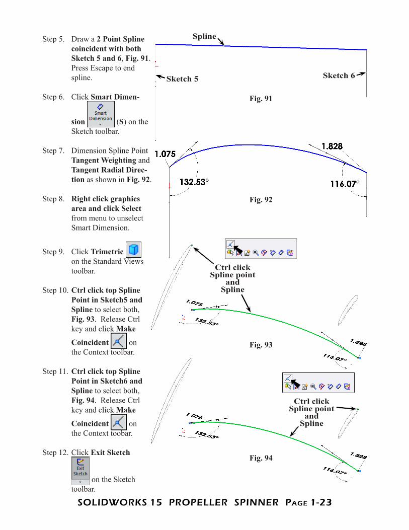
Step 5. Draw a 2 Point Spline coincident with both Sketch 5 and 6, Fig. 91. Press Escape to end spline.
Step 6. Click Smart Dimen-
sion (S) on the Sketch toolbar.
Step 7. Dimension Spline Point Tangent Weighting and Tangent Radial Direc-tion as shown in Fig. 92.
Step 8. Right click graphics area and click Select from menu to unselect Smart Dimension.
Step 9. Click Trimetric on the Standard Views toolbar.
Step 10. Ctrl click top Spline Point in Sketch5 and Spline to select both, Fig. 93. Release Ctrl key and click Make
Coincident on the Context toolbar.
Step 11. Ctrl click top Spline Point in Sketch6 and Spline to select both, Fig. 94. Release Ctrl key and click Make
Coincident on the Context toobar.
Step 12. Click Exit Sketch
on the Sketch toolbar.
Fig. 92
Fig. 91
Spline
Sketch 5 Sketch 6
Fig. 93
Fig. 94
Ctrl click Spline point
and Spline
Ctrl click Spline point
and Spline
SOLIDWORKS 15 PROPELLER SPINNER PagE 1-24
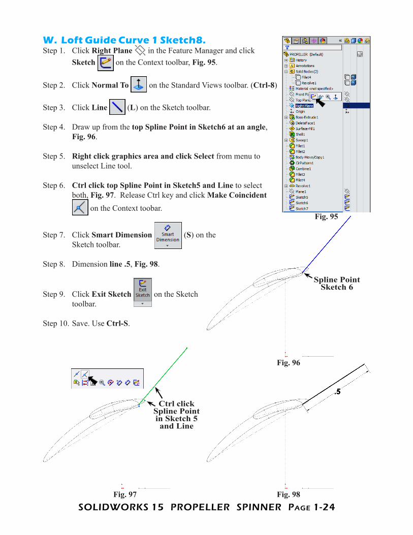
W. Loft Guide Curve 1 Sketch8.Step 1. Click Right Plane in the Feature Manager and click
Sketch on the Context toolbar, Fig. 95.
Step 2. Click Normal To on the Standard Views toolbar. (Ctrl-8)
Step 3. Click Line (L) on the Sketch toolbar.
Step 4. Draw up from the top Spline Point in Sketch6 at an angle, Fig. 96.
Step 5. Right click graphics area and click Select from menu to unselect Line tool.
Step 6. Ctrl click top Spline Point in Sketch5 and Line to select both, Fig. 97. Release Ctrl key and click Make Coincident
on the Context toobar.
Step 7. Click Smart Dimension (S) on the Sketch toolbar.
Step 8. Dimension line .5, Fig. 98.
Step 9. Click Exit Sketch on the Sketch toolbar.
Step 10. Save. Use Ctrl-S.
Fig. 95
Fig. 98Fig. 97
Fig. 96
Spline Point Sketch 6
Ctrl click Spline Point in Sketch 5 and Line
SOLIDWORKS 15 PROPELLER SPINNER PagE 1-25
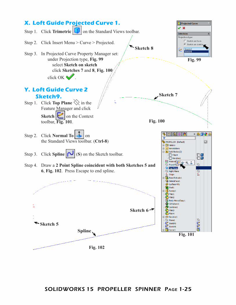
X. Loft Guide Projected Curve 1.Step 1. Click Trimetric on the Standard Views toolbar.
Step 2. Click Insert Menu > Curve > Projected.
Step 3. In Projected Curve Property Manager set: under Projection type, Fig. 99 select Sketch on sketch click Sketches 7 and 8, Fig. 100 click OK .
Y. Loft Guide Curve 2 Sketch9.
Step 1. Click Top Plane in the Feature Manager and click
Sketch on the Context toolbar, Fig. 101.
Step 2. Click Normal To on the Standard Views toolbar. (Ctrl-8)
Step 3. Click Spline (S) on the Sketch toolbar.
Step 4. Draw a 2 Point Spline coincident with both Sketches 5 and 6, Fig. 102. Press Escape to end spline.
Fig. 99
Fig. 100
Sketch 8
Sketch 7
Fig. 101
Fig. 102
SplineSketch 5
Sketch 6
SOLIDWORKS 15 PROPELLER SPINNER PagE 1-26
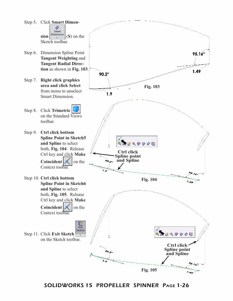
Step 5. Click Smart Dimen-
sion (S) on the Sketch toolbar.
Step 6. Dimension Spline Point Tangent Weighting and Tangent Radial Direc-tion as shown in Fig. 103.
Step 7. Right click graphics area and click Select from menu to unselect Smart Dimension.
Step 8. Click Trimetric on the Standard Views toolbar.
Step 9. Ctrl click bottom Spline Point in Sketch5 and Spline to select both, Fig. 104. Release Ctrl key and click Make Coincident on the Context toobar.
Step 10. Ctrl click bottom Spline Point in Sketch6 and Spline to select both, Fig. 105. Release Ctrl key and click Make Coincident on the Context toolbar.
Step 11. Click Exit Sketch on the Sketch toolbar.
Fig. 103
Fig. 104
Ctrl click Spline point and Spline
Fig. 105
Ctrl click Spline point and Spline
SOLIDWORKS 15 PROPELLER SPINNER PagE 1-27
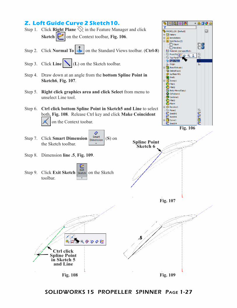
Z. Loft Guide Curve 2 Sketch10.Step 1. Click Right Plane in the Feature Manager and click
Sketch on the Context toolbar, Fig. 106.
Step 2. Click Normal To on the Standard Views toolbar. (Ctrl-8)
Step 3. Click Line (L) on the Sketch toolbar.
Step 4. Draw down at an angle from the bottom Spline Point in Sketch6, Fig. 107.
Step 5. Right click graphics area and click Select from menu to unselect Line tool.
Step 6. Ctrl click bottom Spline Point in Sketch5 and Line to select both, Fig. 108. Release Ctrl key and click Make Coincident
on the Context toobar.
Step 7. Click Smart Dimension (S) on the Sketch toolbar.
Step 8. Dimension line .5, Fig. 109.
Step 9. Click Exit Sketch on the Sketch toolbar.
Fig. 106
Fig. 107
Fig. 109Fig. 108
Spline Point Sketch 6
Ctrl click Spline Point in Sketch 5 and Line
SOLIDWORKS 15 PROPELLER SPINNER PagE 1-28
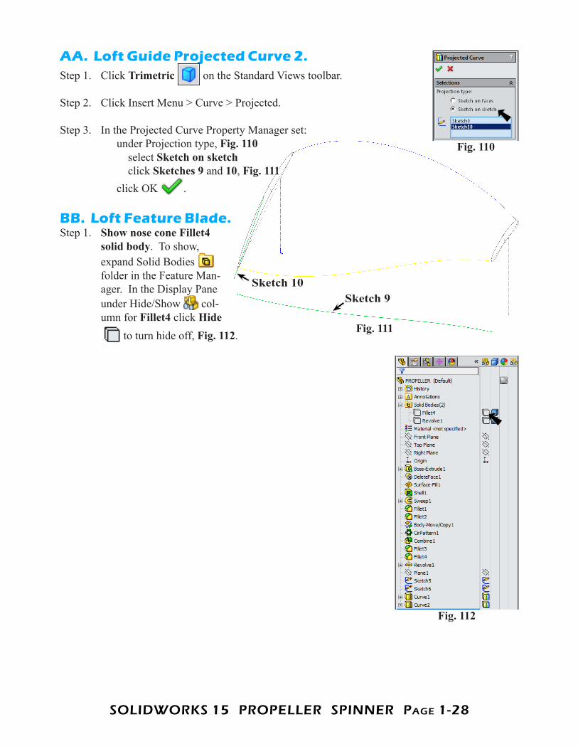
AA. Loft Guide Projected Curve 2.Step 1. Click Trimetric on the Standard Views toolbar.
Step 2. Click Insert Menu > Curve > Projected.
Step 3. In the Projected Curve Property Manager set: under Projection type, Fig. 110 select Sketch on sketch click Sketches 9 and 10, Fig. 111 click OK .
BB. Loft Feature Blade.Step 1. Show nose cone Fillet4
solid body. To show, expand Solid Bodies folder in the Feature Man-ager. In the Display Pane under Hide/Show col-umn for Fillet4 click Hide
to turn hide off, Fig. 112.
Fig. 110
Fig. 111
Sketch 10Sketch 9
Fig. 112
SOLIDWORKS 15 PROPELLER SPINNER PagE 1-29
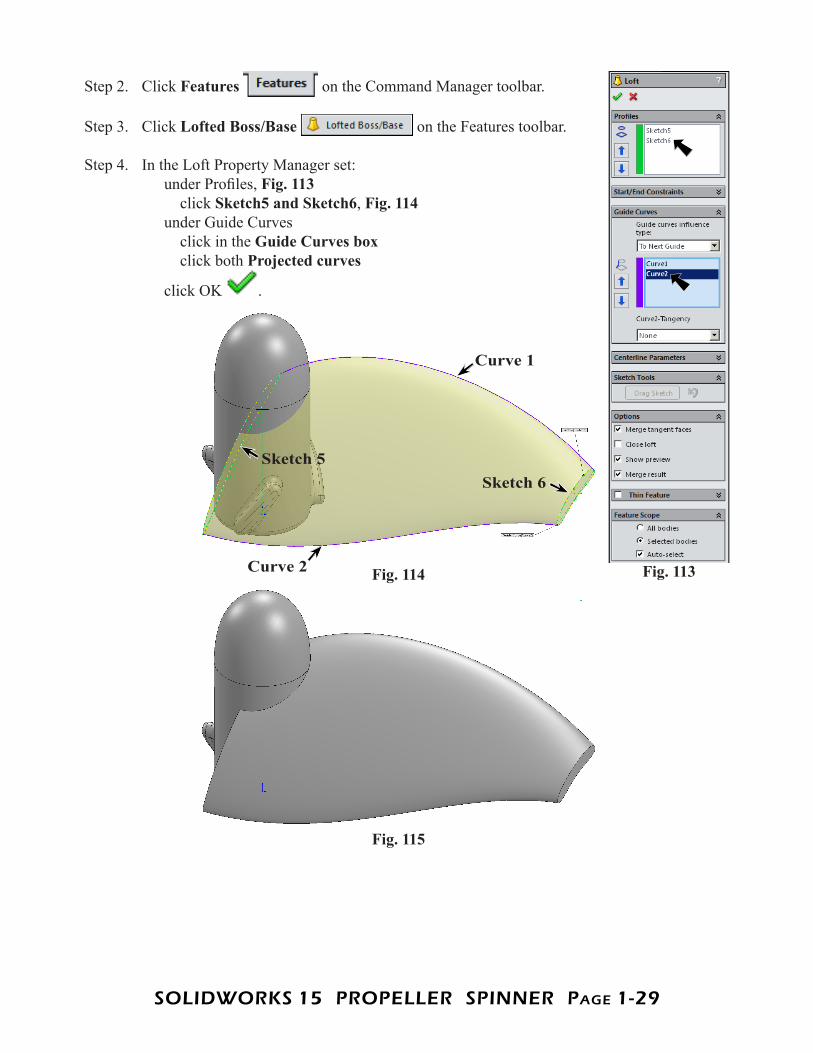
Step 2. Click Features on the Command Manager toolbar.
Step 3. Click Lofted Boss/Base on the Features toolbar.
Step 4. In the Loft Property Manager set: under Profiles, Fig. 113 click Sketch5 and Sketch6, Fig. 114 under Guide Curves click in the Guide Curves box click both Projected curves
click OK .
Fig. 113Fig. 114
Sketch 5Sketch 6
Curve 1
Curve 2
Fig. 115
SOLIDWORKS 15 PROPELLER SPINNER PagE 1-30
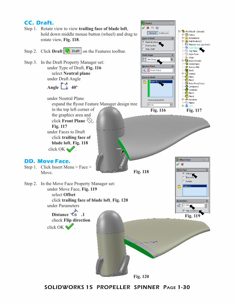
CC. Draft.Step 1. Rotate view to view trailing face of blade loft,
hold down middle mouse button (wheel) and drag to rotate view, Fig. 118.
Step 2. Click Draft on the Features toolbar.
Step 3. In the Draft Property Manager set: under Type of Draft, Fig. 116 select Neutral plane under Draft Angle
Angle 40º
under Neutral Plane expand the flyout Feature Manager design tree in the top left corner of the graphics area and click Front Plane , Fig. 117 under Faces to Draft click trailing face of blade loft, Fig. 118 click OK .
DD. Move Face.Step 1. Click Insert Menu > Face >
Move.
Step 2. In the Move Face Property Manager set: under Move Face, Fig. 119 select Offset click trailing face of blade loft, Fig. 120 under Parameters
Distance .1 check Flip direction click OK .
Fig. 116 Fig. 117
Fig. 118
Fig. 120
Fig. 119
SOLIDWORKS 15 PROPELLER SPINNER PagE 1-31
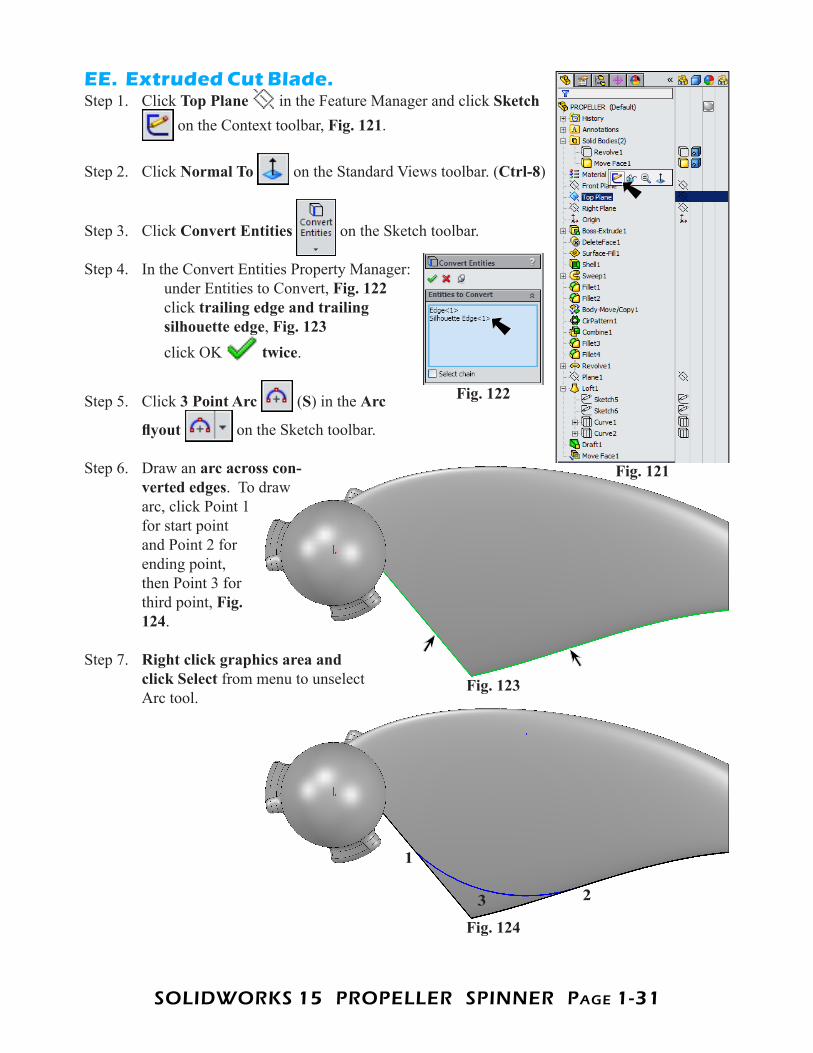
EE. Extruded Cut Blade.Step 1. Click Top Plane in the Feature Manager and click Sketch
on the Context toolbar, Fig. 121.
Step 2. Click Normal To on the Standard Views toolbar. (Ctrl-8)
Step 3. Click Convert Entities on the Sketch toolbar.
Step 4. In the Convert Entities Property Manager: under Entities to Convert, Fig. 122 click trailing edge and trailing silhouette edge, Fig. 123 click OK twice.
Step 5. Click 3 Point Arc (S) in the Arc
flyout on the Sketch toolbar.
Step 6. Draw an arc across con-verted edges. To draw arc, click Point 1 for start point and Point 2 for ending point, then Point 3 for third point, Fig. 124.
Step 7. Right click graphics area and click Select from menu to unselect Arc tool.
Fig. 121
Fig. 122
Fig. 123
Fig. 124
3 2
1
SOLIDWORKS 15 PROPELLER SPINNER PagE 1-32
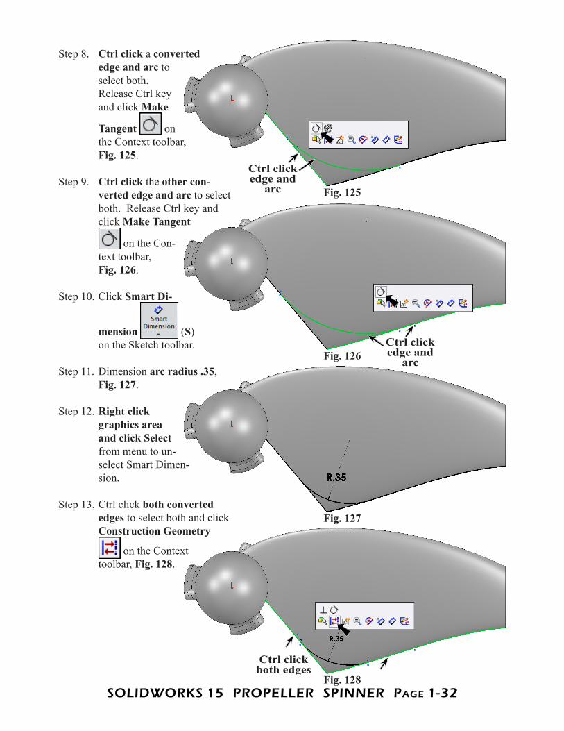
Step 8. Ctrl click a converted edge and arc to select both. Release Ctrl key and click Make
Tangent on the Context toolbar, Fig. 125.
Step 9. Ctrl click the other con-verted edge and arc to select both. Release Ctrl key and click Make Tangent
on the Con-text toolbar, Fig. 126.
Step 10. Click Smart Di-
mension (S) on the Sketch toolbar.
Step 11. Dimension arc radius .35, Fig. 127.
Step 12. Right click graphics area and click Select from menu to un-select Smart Dimen-sion.
Step 13. Ctrl click both converted edges to select both and click Construction Geometry
on the Context toolbar, Fig. 128.
Fig. 125
Fig. 126
Fig. 127
Fig. 128
Ctrl click edge and
arc
Ctrl click edge and
arc
Ctrl click both edges
SOLIDWORKS 15 PROPELLER SPINNER PagE 1-33
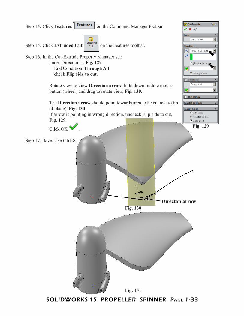
Step 14. Click Features on the Command Manager toolbar.
Step 15. Click Extruded Cut on the Features toolbar.
Step 16. In the Cut-Extrude Property Manager set: under Direction 1, Fig. 129 End Condition Through All check Flip side to cut. Rotate view to view Direction arrow, hold down middle mouse button (wheel) and drag to rotate view, Fig. 130. The Direction arrow should point towards area to be cut away (tip of blade), Fig. 130. If arrow is pointing in wrong direction, uncheck Flip side to cut, Fig. 129.
Click OK .
Step 17. Save. Use Ctrl-S.
Fig. 129
Fig. 130
Fig. 131
Directon arrow
SOLIDWORKS 15 PROPELLER SPINNER PagE 1-34
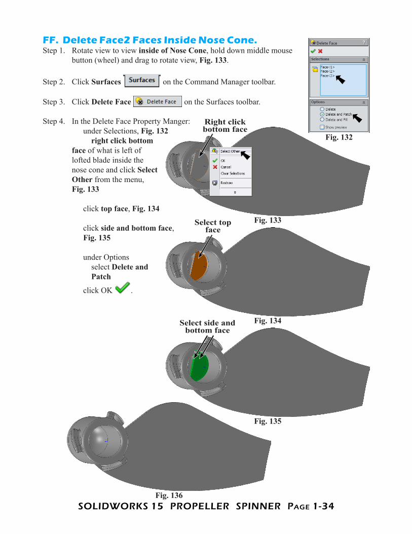
FF. Delete Face2 Faces Inside Nose Cone.Step 1. Rotate view to view inside of Nose Cone, hold down middle mouse
button (wheel) and drag to rotate view, Fig. 133.
Step 2. Click Surfaces on the Command Manager toolbar.
Step 3. Click Delete Face on the Surfaces toolbar.
Step 4. In the Delete Face Property Manger: under Selections, Fig. 132 right click bottom face of what is left of lofted blade inside the nose cone and click Select Other from the menu,Fig. 133 click top face, Fig. 134 click side and bottom face, Fig. 135 under Options select Delete and Patch
click OK .
Fig. 132
Fig. 133
Fig. 134
Fig. 135
Fig. 136
Right click bottom face
Select top face
Select side and bottom face
SOLIDWORKS 15 PROPELLER SPINNER PagE 1-35
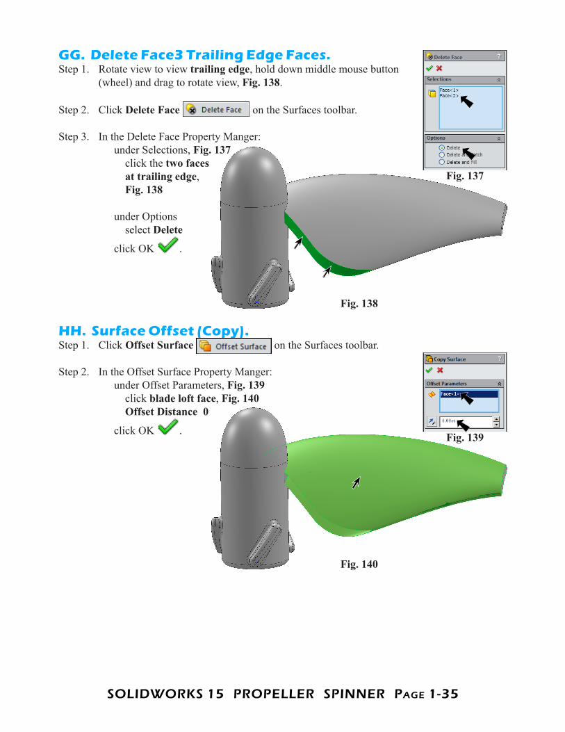
GG. Delete Face3 Trailing Edge Faces.Step 1. Rotate view to view trailing edge, hold down middle mouse button
(wheel) and drag to rotate view, Fig. 138.
Step 2. Click Delete Face on the Surfaces toolbar.
Step 3. In the Delete Face Property Manger: under Selections, Fig. 137 click the two faces at trailing edge, Fig. 138 under Options select Delete
click OK .
HH. Surface Offset (Copy).Step 1. Click Offset Surface on the Surfaces toolbar.
Step 2. In the Offset Surface Property Manger: under Offset Parameters, Fig. 139 click blade loft face, Fig. 140 Offset Distance 0
click OK .
Fig. 137
Fig. 138
Fig. 140
Fig. 139
SOLIDWORKS 15 PROPELLER SPINNER PagE 1-36
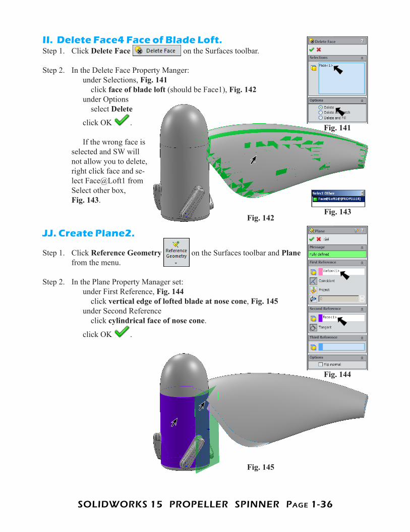
II. Delete Face4 Face of Blade Loft.Step 1. Click Delete Face on the Surfaces toolbar.
Step 2. In the Delete Face Property Manger: under Selections, Fig. 141 click face of blade loft (should be Face1), Fig. 142 under Options select Delete
click OK . If the wrong face is selected and SW will not allow you to delete, right click face and se-lect Face@Loft1 from Select other box, Fig. 143.
JJ. Create Plane2.
Step 1. Click Reference Geometry on the Surfaces toolbar and Plane from the menu.
Step 2. In the Plane Property Manager set: under First Reference, Fig. 144 click vertical edge of lofted blade at nose cone, Fig. 145 under Second Reference click cylindrical face of nose cone.
click OK .
Fig. 142
Fig. 141
Fig. 143
Fig. 145
Fig. 144
SOLIDWORKS 15 PROPELLER SPINNER PagE 1-37
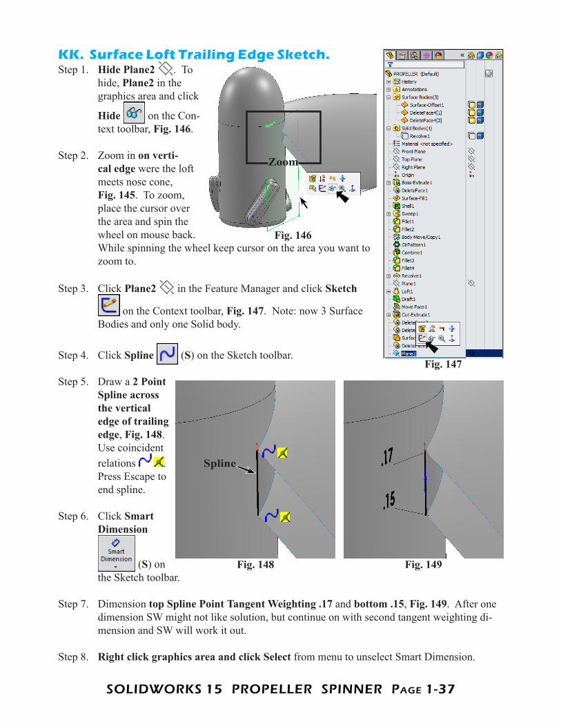
KK. Surface Loft Trailing Edge Sketch.Step 1. Hide Plane2 . To
hide, Plane2 in the graphics area and click
Hide on the Con-text toolbar, Fig. 146.
Step 2. Zoom in on verti-cal edge were the loft meets nose cone, Fig. 145. To zoom, place the cursor over the area and spin the wheel on mouse back. While spinning the wheel keep cursor on the area you want to zoom to.
Step 3. Click Plane2 in the Feature Manager and click Sketch
on the Context toolbar, Fig. 147. Note: now 3 Surface Bodies and only one Solid body.
Step 4. Click Spline (S) on the Sketch toolbar.
Step 5. Draw a 2 Point Spline across the vertical edge of trailing edge, Fig. 148. Use coincident relations . Press Escape to end spline.
Step 6. Click Smart Dimension
(S) on the Sketch toolbar.
Step 7. Dimension top Spline Point Tangent Weighting .17 and bottom .15, Fig. 149. After one dimension SW might not like solution, but continue on with second tangent weighting di-mension and SW will work it out.
Step 8. Right click graphics area and click Select from menu to unselect Smart Dimension.
Fig. 146
Zoom
Fig. 147
Fig. 149Fig. 148
Spline
SOLIDWORKS 15 PROPELLER SPINNER PagE 1-38
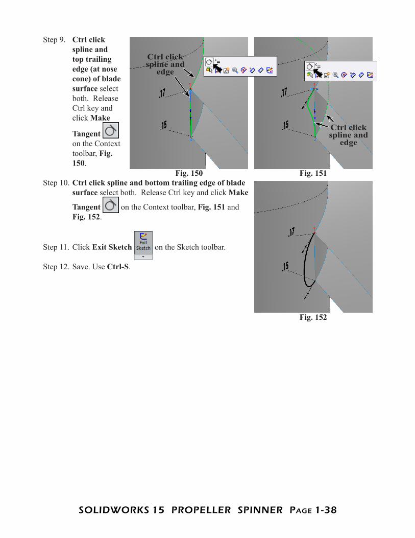
Step 9. Ctrl click spline and top trailing edge (at nose cone) of blade surface select both. Release Ctrl key and click Make
Tangent on the Context toolbar, Fig. 150.
Step 10. Ctrl click spline and bottom trailing edge of blade surface select both. Release Ctrl key and click Make
Tangent on the Context toolbar, Fig. 151 and Fig. 152.
Step 11. Click Exit Sketch on the Sketch toolbar.
Step 12. Save. Use Ctrl-S.
Fig. 151Fig. 150
Fig. 152
Ctrl click spline and
edge
Ctrl click spline and
edge
SOLIDWORKS 15 PROPELLER SPINNER PagE 1-39
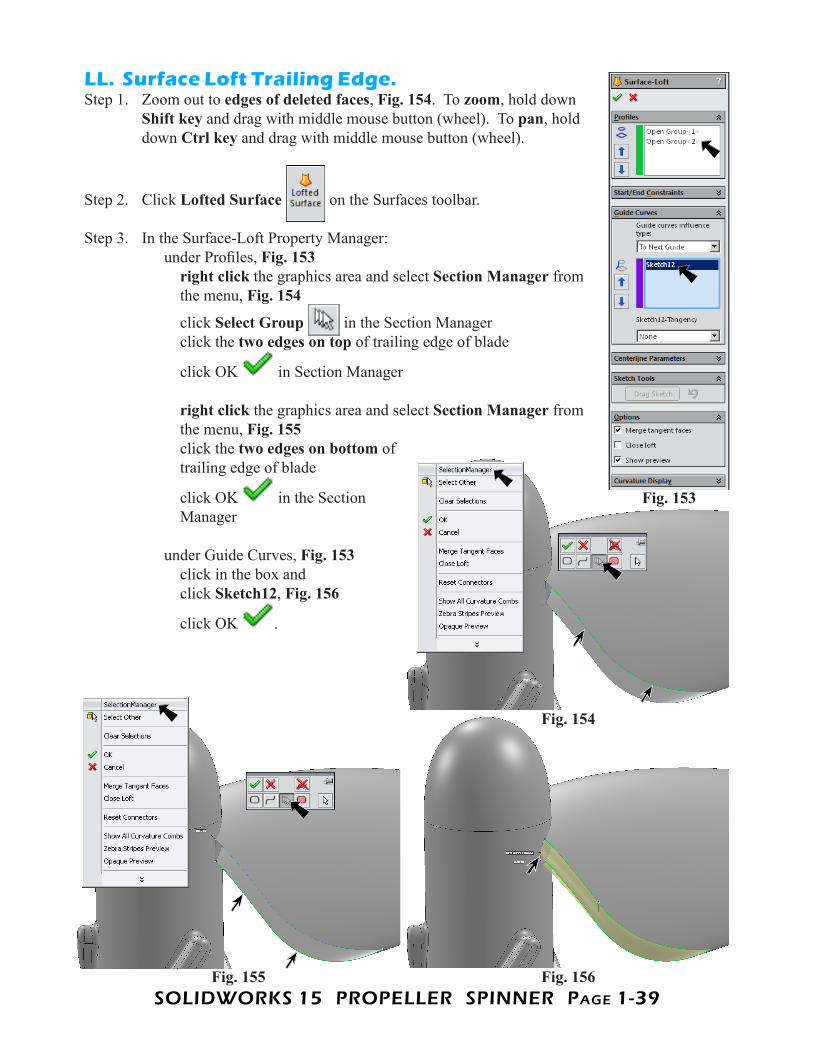
LL. Surface Loft Trailing Edge.Step 1. Zoom out to edges of deleted faces, Fig. 154. To zoom, hold down
Shift key and drag with middle mouse button (wheel). To pan, hold down Ctrl key and drag with middle mouse button (wheel).
Step 2. Click Lofted Surface on the Surfaces toolbar.
Step 3. In the Surface-Loft Property Manager: under Profiles, Fig. 153 right click the graphics area and select Section Manager from the menu, Fig. 154
click Select Group in the Section Manager click the two edges on top of trailing edge of blade
click OK in Section Manager right click the graphics area and select Section Manager from the menu, Fig. 155 click the two edges on bottom of trailing edge of blade
click OK in the Section Manager under Guide Curves, Fig. 153 click in the box and click Sketch12, Fig. 156
click OK .
Fig. 153
Fig. 156Fig. 155
Fig. 154
SOLIDWORKS 15 PROPELLER SPINNER PagE 1-40
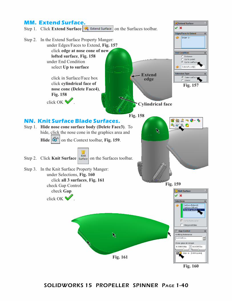
MM. Extend Surface.Step 1. Click Extend Surface on the Surfaces toolbar.
Step 2. In the Extend Surface Property Manger: under Edges/Faces to Extend, Fig. 157 click edge at nose cone of new lofted surface, Fig. 158 under End Condition select Up to surface click in Surface/Face box click cylindrical face of nose cone (Delete Face4), Fig. 158
click OK .
NN. Knit Surface Blade Surfaces.Step 1. Hide nose cone surface body (Delete Face3). To
hide, click the nose cone in the graphics area and
Hide on the Context toolbar, Fig. 159.
Step 2. Click Knit Surface on the Surfaces toolbar.
Step 3. In the Knit Surface Property Manger: under Selections, Fig. 160 click all 3 surfaces, Fig. 161 check Gap Control check Gap
click OK .
Fig. 157
Extend edge
Cylindrical face
Fig. 158
Fig. 159
Fig. 160
Fig. 161
SOLIDWORKS 15 PROPELLER SPINNER PagE 1-41
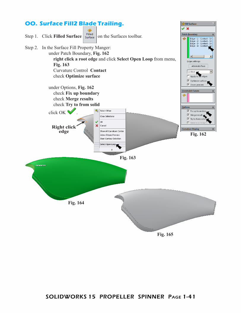
OO. Surface Fill2 Blade Trailing.
Step 1. Click Filled Surface on the Surfaces toolbar.
Step 2. In the Surface Fill Property Manger: under Patch Boundary, Fig. 162 right click a root edge and click Select Open Loop from menu, Fig. 163 Curvature Control Contact check Optimize surface under Options, Fig. 162 check Fix up boundary check Merge results check Try to from solid
click OK .
Fig. 162
Fig. 163
Fig. 165
Fig. 164
Right click edge
SOLIDWORKS 15 PROPELLER SPINNER PagE 1-42
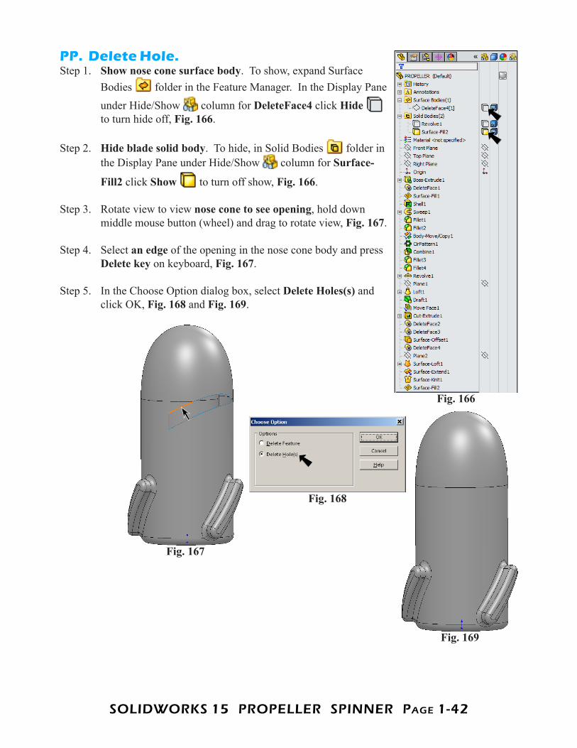
PP. Delete Hole.Step 1. Show nose cone surface body. To show, expand Surface
Bodies folder in the Feature Manager. In the Display Pane under Hide/Show column for DeleteFace4 click Hideto turn hide off, Fig. 166.
Step 2. Hide blade solid body. To hide, in Solid Bodies folder in the Display Pane under Hide/Show column for Surface-
Fill2 click Show to turn off show, Fig. 166.
Step 3. Rotate view to view nose cone to see opening, hold down middle mouse button (wheel) and drag to rotate view, Fig. 167.
Step 4. Select an edge of the opening in the nose cone body and press Delete key on keyboard, Fig. 167.
Step 5. In the Choose Option dialog box, select Delete Holes(s) and click OK, Fig. 168 and Fig. 169.
Fig. 166
Fig. 168
Fig. 167
Fig. 169
SOLIDWORKS 15 PROPELLER SPINNER PagE 1-43
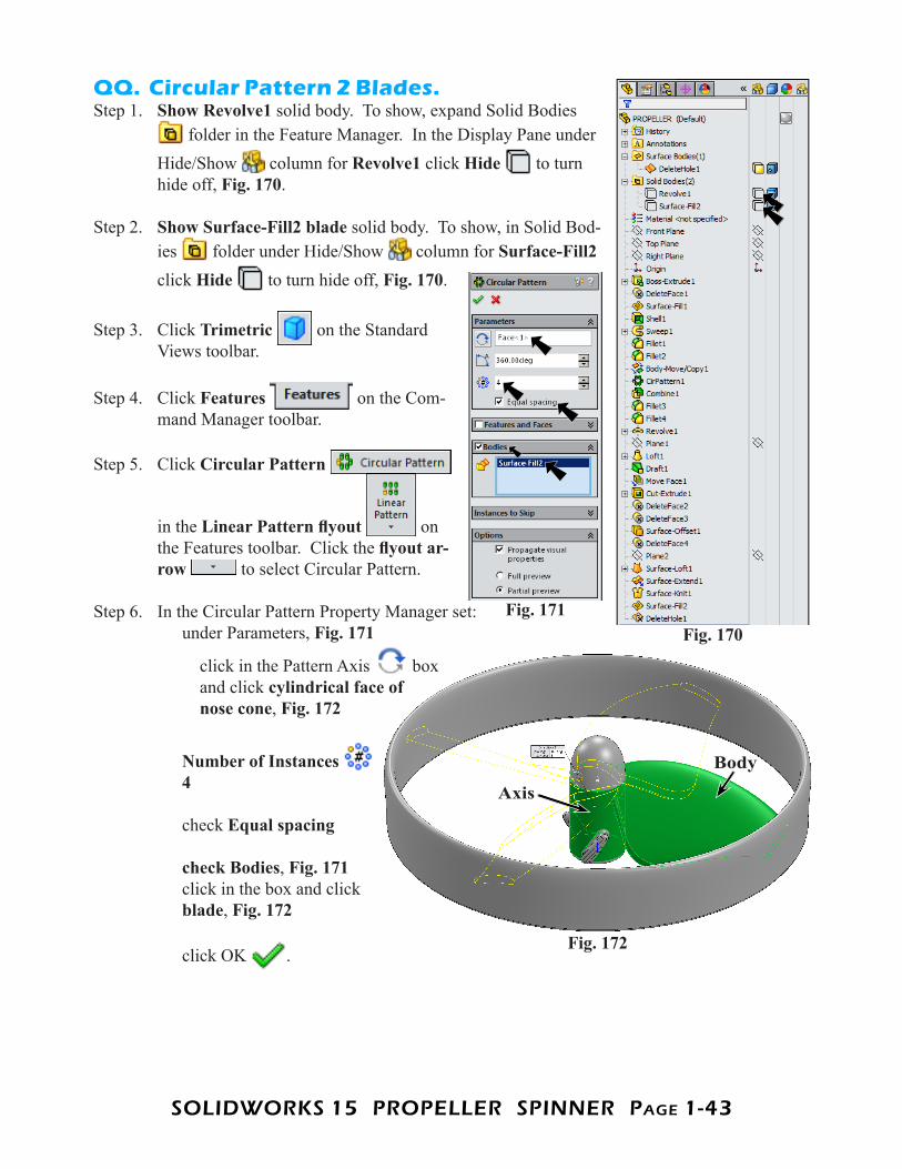
QQ. Circular Pattern 2 Blades.Step 1. Show Revolve1 solid body. To show, expand Solid Bodies
folder in the Feature Manager. In the Display Pane under Hide/Show column for Revolve1 click Hide to turn hide off, Fig. 170.
Step 2. Show Surface-Fill2 blade solid body. To show, in Solid Bod-ies folder under Hide/Show column for Surface-Fill2 click Hide to turn hide off, Fig. 170.
Step 3. Click Trimetric on the Standard Views toolbar.
Step 4. Click Features on the Com-mand Manager toolbar.
Step 5. Click Circular Pattern
in the Linear Pattern flyout on the Features toolbar. Click the flyout ar-row to select Circular Pattern.
Step 6. In the Circular Pattern Property Manager set: under Parameters, Fig. 171
click in the Pattern Axis box and click cylindrical face of nose cone, Fig. 172
Number of Instances 4 check Equal spacing check Bodies, Fig. 171 click in the box and click blade, Fig. 172 click OK .
Fig. 170Fig. 171
Fig. 172
Axis
Body
SOLIDWORKS 15 PROPELLER SPINNER PagE 1-44
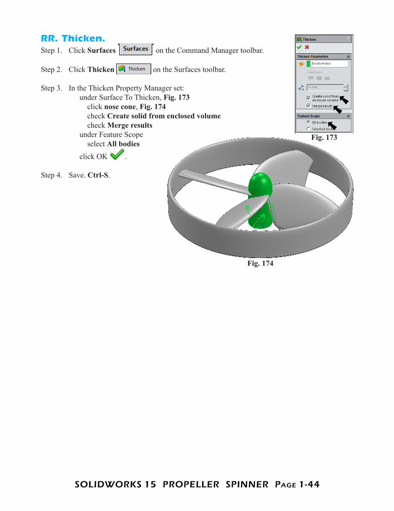
RR. Thicken.Step 1. Click Surfaces on the Command Manager toolbar.
Step 2. Click Thicken on the Surfaces toolbar.
Step 3. In the Thicken Property Manager set: under Surface To Thicken, Fig. 173 click nose cone, Fig. 174 check Create solid from enclosed volume check Merge results under Feature Scope select All bodies click OK .
Step 4. Save. Ctrl-S.
Fig. 174
Fig. 173
SOLIDWORKS 15 PROPELLER SPINNER PagE 1-45
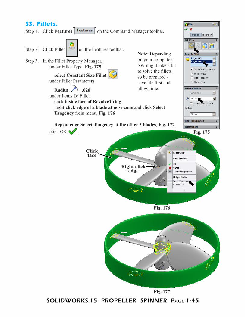
SS. Fillets.Step 1. Click Features on the Command Manager toolbar.
Step 2. Click Fillet on the Features toolbar.
Step 3. In the Fillet Property Manager, under Fillet Type, Fig. 175
select Constant Size Fillet under Fillet Parameters
Radius .028 under Items To Fillet click inside face of Revolve1 ring right click edge of a blade at nose cone and click Select Tangency from menu, Fig. 176 Repeat edge Select Tangency at the other 3 blades, Fig. 177 click OK . Fig. 175
Fig. 176
Fig. 177
Click face
Right click edge
Note: Depending on your computer, SW might take a bit to solve the fillets so be prepared - save file first and allow time.
SOLIDWORKS 15 PROPELLER SPINNER PagE 1-46
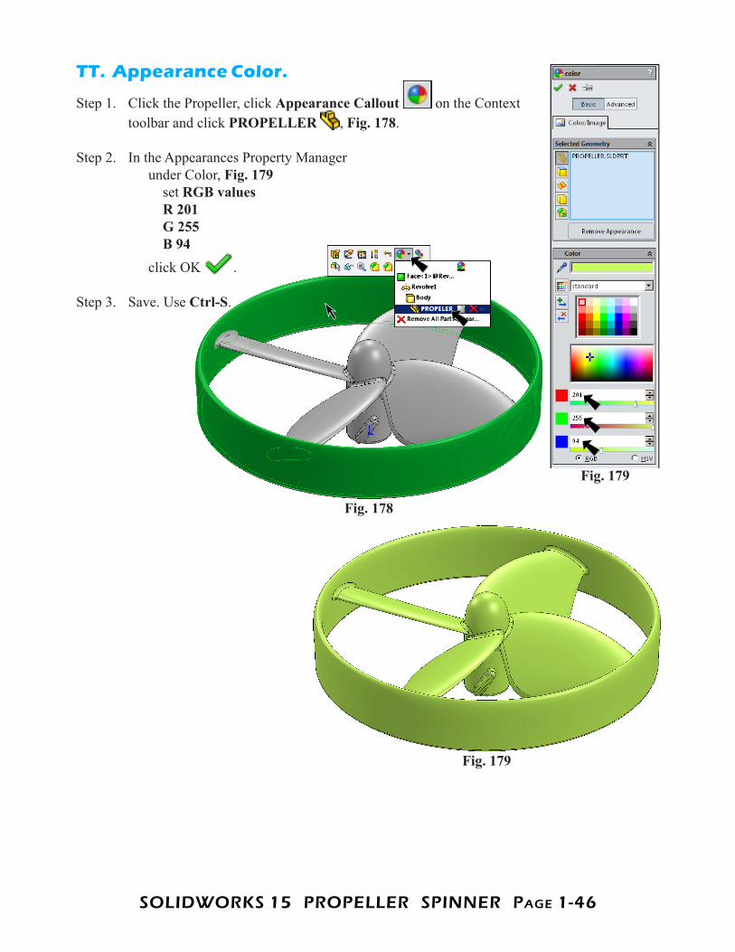
TT. Appearance Color.
Step 1. Click the Propeller, click Appearance Callout on the Context toolbar and click PROPELLER , Fig. 178.
Step 2. In the Appearances Property Manager under Color, Fig. 179 set RGB values R 201 G 255 B 94 click OK .
Step 3. Save. Use Ctrl-S.
Fig. 179
Fig. 178
Fig. 179


![Predictive Modeling of Spinner Dolphin (Stenella ... · spinner), S.l. centroamericana (Central American spinner) and S.l. roseiventris (Dwarf spinner) [19,20]. The Gray’s spinner](https://static.fdocuments.net/doc/165x107/5f87e3e5d2d3037d75174768/predictive-modeling-of-spinner-dolphin-stenella-spinner-sl-centroamericana.jpg)