Chaotic optical communications over 100-km fiber ...
4
Chaotic optical communications over 100-km fiber transmission at 30-Gb/s bit rate JUNXIANG KE, 1 LILIN YI, 1, *GUANGQIONG XIA, 2 AND WEISHENG HU 1 1 State Key Laboratory of Advanced Optical Communication Systems and Networks, Shanghai Institute for Advanced Communication and Data Science, Shanghai Jiao Tong University, Shanghai 200240, China 2 School of Physics, Southwest University, Chongqing 400715, China *Corresponding author: [email protected] Received 27 December 2017; revised 14 February 2018; accepted 19 February 2018; posted 20 February 2018 (Doc. ID 318491); published 12 March 2018 For the first time, to the best of our knowledge, we exper- imentally demonstrate a successful 30-Gb/s signal transmis- sion of a duobinary message hidden in a chaotic optical carrier over 100-km fiber. Thanks to the duobinary modu- lation format with high spectral efficiency, the 30-Gb/s sig- nal can be encrypted by a 10-GHz-wide chaotic carrier. A digital signal processing technique can be used to convert duobinary data into binary data on the receiver side. This proposal lowers the requirement for wideband chaos gen- eration and synchronization in high-speed long-distance chaotic optical communications, and fiber dispersion com- pensation can also be simplified, which has potential to be used in high-speed long-distance secure optical communi- cations. © 2018 Optical Society of America OCIS codes: (140.1540) Chaos; (060.4785) Optical security and encryption; (060.2330) Fiber optics communications. https://doi.org/10.1364/OL.43.001323 Since the first demonstration of chaos synchronization in 1990, the chaos system, used as a hardware encryption method in op- tical communications, has drawn much attention [1]. Many schemes based on the nonlinearity of lasers and modulators have been proposed in optical secure transmission [2–13]. From the viewpoint of practical applications, the modulator- based chaotic system has the benefit of simplified synchroniza- tion. The first field trial of chaotic optical communications based on a Mach–Zehnder modulator (MZM) scheme has been successfully demonstrated to support 2.4-Gb/s bit rate and 120-km transmission distance in Athens ’ metro-network [9]. Further, the first 10-Gb/s field experiment of chaotic optical communication based on a phase modulator and Mach– Zehnder interferometer (MZI) scheme over more than 100 km fiber has been successfully demonstrated [11]. However, chaotic optical communications encounter prob- lems in high-speed and long-distance fiber transmission. First, the modulation formats used in the traditional chaotic optical communication systems are mainly on–off keying (OOK) and differential phase-shift keying (DPSK); therefore, a wideband chaos signal is needed for high-speed binary signal encryption. But the chaotic bandwidth of a laser-based chaotic system is limited by the relaxation oscillation, while the chaotic band- width of a modulator-based chaotic system is limited by the electrical devices. Therefore, many schemes have been pro- posed to generate wideband chaos [14–19]. But it is not easy to realize wideband chaos synchronization. Also, wideband chaos is very sensitive to fiber dispersion [20], which makes the synchronization quality become worse, and a part of the unsynchronized chaos signal is converted to noise, which makes the signal-to-noise ratio (SNR) become worse. Due to the above difficulties, there have been no demonstrations of chaotic optical communications beyond 10 Gb/s until now. In this Letter, the difficulty of high-speed long-distance transmission described above can be solved; a 30-Gb/s secure signal transmission over 100-km single-mode fiber (SMF) based on 10-GHz optical and electrical devices is experimentally demonstrated. The message modulation format is duobinary, while the dispersion compensation fiber (DCF) and tunable dispersion compensation (TDC) module are used for dispersion compensation; an erbium-doped fiber amplifier (EDFA) is used for optical signal amplification. The performance of the system with different mask efficiencies has been studied in back-to-back (BtB) and 100-km transmission. Digital signal processing (DSP) is employed on the receiver side to convert duobinary into binary data for bit-error-rate (BER) measurement, and 30- Gb/s chaotic optical communications over 100-km transmission has been realized with BER less than 3.8 × 10 -3 , which is the hard decision forward error correction (HD-FEC) threshold. We hope the proposed scheme can open a new window for high-speed and long-distance chaotic optical communications. The experiment setup of the proposed scheme is illustrated in Fig. 1. A continuous-wave (CW) light with power of 14 dBm from a 1545-nm laser diode (LD2) with a narrow line- width of 100 kHz is launched into a AVANEX MZM (MZM2) with a 3-dB bandwidth of 10 GHz and a half wave voltage of 3.8 V. The MZM2 provides nonlinear transfer function cos 2 x Ψ, and the optical intensity of the injected light is modulated by the output of the broadband radio-frequency (RF) driver with a 3-dB bandwidth of 30 kHz–10 GHz, a gain of 45 dB, and maximum output peak-to-peak voltage of 10 V. Letter Vol. 43, No. 6 / 15 March 2018 / Optics Letters 1323 0146-9592/18/061323-04 Journal © 2018 Optical Society of America
Transcript of Chaotic optical communications over 100-km fiber ...
Chaotic optical communications over 100-kmfiber transmission at 30-Gb/s bit rateJUNXIANG KE,1 LILIN YI,1,* GUANGQIONG XIA,2 AND WEISHENG HU1
1State Key Laboratory of Advanced Optical Communication Systems and Networks, Shanghai Institute for Advanced Communication andData Science, Shanghai Jiao Tong University, Shanghai 200240, China2School of Physics, Southwest University, Chongqing 400715, China*Corresponding author: [email protected]
Received 27 December 2017; revised 14 February 2018; accepted 19 February 2018; posted 20 February 2018 (Doc. ID 318491);published 12 March 2018
For the first time, to the best of our knowledge, we exper-imentally demonstrate a successful 30-Gb/s signal transmis-sion of a duobinary message hidden in a chaotic opticalcarrier over 100-km fiber. Thanks to the duobinary modu-lation format with high spectral efficiency, the 30-Gb/s sig-nal can be encrypted by a 10-GHz-wide chaotic carrier. Adigital signal processing technique can be used to convertduobinary data into binary data on the receiver side. Thisproposal lowers the requirement for wideband chaos gen-eration and synchronization in high-speed long-distancechaotic optical communications, and fiber dispersion com-pensation can also be simplified, which has potential to beused in high-speed long-distance secure optical communi-cations. © 2018 Optical Society of America
OCIS codes: (140.1540) Chaos; (060.4785) Optical security and
encryption; (060.2330) Fiber optics communications.
https://doi.org/10.1364/OL.43.001323
Since the first demonstration of chaos synchronization in 1990,the chaos system, used as a hardware encryption method in op-tical communications, has drawn much attention [1]. Manyschemes based on the nonlinearity of lasers and modulatorshave been proposed in optical secure transmission [2–13].From the viewpoint of practical applications, the modulator-based chaotic system has the benefit of simplified synchroniza-tion. The first field trial of chaotic optical communicationsbased on a Mach–Zehnder modulator (MZM) scheme has beensuccessfully demonstrated to support 2.4-Gb/s bit rate and120-km transmission distance in Athens’ metro-network [9].Further, the first 10-Gb/s field experiment of chaotic opticalcommunication based on a phase modulator and Mach–Zehnder interferometer (MZI) scheme over more than 100 kmfiber has been successfully demonstrated [11].
However, chaotic optical communications encounter prob-lems in high-speed and long-distance fiber transmission. First,the modulation formats used in the traditional chaotic opticalcommunication systems are mainly on–off keying (OOK) anddifferential phase-shift keying (DPSK); therefore, a wideband
chaos signal is needed for high-speed binary signal encryption.But the chaotic bandwidth of a laser-based chaotic system islimited by the relaxation oscillation, while the chaotic band-width of a modulator-based chaotic system is limited by theelectrical devices. Therefore, many schemes have been pro-posed to generate wideband chaos [14–19]. But it is not easyto realize wideband chaos synchronization. Also, widebandchaos is very sensitive to fiber dispersion [20], which makesthe synchronization quality become worse, and a part of theunsynchronized chaos signal is converted to noise, which makesthe signal-to-noise ratio (SNR) become worse. Due to theabove difficulties, there have been no demonstrations of chaoticoptical communications beyond 10 Gb/s until now.
In this Letter, the difficulty of high-speed long-distancetransmission described above can be solved; a 30-Gb/s securesignal transmission over 100-km single-mode fiber (SMF) basedon 10-GHz optical and electrical devices is experimentallydemonstrated. The message modulation format is duobinary,while the dispersion compensation fiber (DCF) and tunabledispersion compensation (TDC) module are used for dispersioncompensation; an erbium-doped fiber amplifier (EDFA) is usedfor optical signal amplification. The performance of the systemwith different mask efficiencies has been studied in back-to-back(BtB) and 100-km transmission. Digital signal processing (DSP)is employed on the receiver side to convert duobinary intobinary data for bit-error-rate (BER) measurement, and 30-Gb/s chaotic optical communications over 100-km transmissionhas been realized with BER less than 3.8 × 10⁻³, which is thehard decision forward error correction (HD-FEC) threshold.We hope the proposed scheme can open a new window forhigh-speed and long-distance chaotic optical communications.
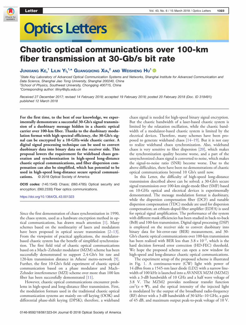
The experiment setup of the proposed scheme is illustratedin Fig. 1. A continuous-wave (CW) light with power of14 dBm from a 1545-nm laser diode (LD2) with a narrow line-width of 100 kHz is launched into a AVANEXMZM (MZM2)with a 3-dB bandwidth of 10 GHz and a half wave voltage of3.8 V. The MZM2 provides nonlinear transfer functioncos2�x �Ψ�, and the optical intensity of the injected lightis modulated by the output of the broadband radio-frequency(RF) driver with a 3-dB bandwidth of 30 kHz–10 GHz, a gainof 45 dB, and maximum output peak-to-peak voltage of 10 V.
Letter Vol. 43, No. 6 / 15 March 2018 / Optics Letters 1323
0146-9592/18/061323-04 Journal © 2018 Optical Society of America
The output light of MZM2 is mixed with the output light froma 1545 nm LD1 with power of 14 dBm modulated by MZM1driven by 30-Gb/s non-return-to-zero OOK (NRZ-OOK)pseudo random binary sequence (PRBS) signal; the 3-dB band-width of MZM1 is 10 GHz. Due to the bandwidth limitationof the modulator, the 30-Gb/s electrical binary data are con-verted to three-level duobinary data. The mixture ratio betweenchaotic carrier and message is controlled by a variable opticalattenuator (VOA1 and VOA2). Through a 50:50 optical cou-pler (OC1), the light after mixture is split into two beams. Onebeam propagates for a few meters of optical fiber until it passesby the VOA3, which is used to control the feedback strength,then it is detected by a broadband amplifier photodiode (PD1)with a 3-dB bandwidth of 10 GHz and a responsivity of125 mV/mW, and the input light power of PD1 is controlledat −5 dBm. The other output light of OC is used for transmis-sion, and the optical isolator (OI) is used to prevent reflectedlight from the SMF, while the VOA4 is used to control theinjection power of the fiber. The encrypted signal is transmittedfor 60-km SMF with 11.7-dB insertion loss (IL), then a DCFwith −936 ps∕nm dispersion value and 3.7-dB IL is used tocompensate the dispersion of SMF, and EDFA1 is used to com-pensate the transmission loss and control the injection power ofthe 40-km SMF with 7.8-dB IL. Then, a TDC with 5.1-dB ILand −764 ps∕nm dispersion value is used for the accuratedispersion compensation, and the output light amplified by
EDFA2 is filtered by a SANTEC optical tunable filter(OTF) with 3-dB bandwidth of 0.4 nm, which is used tosuppress the amplified spontaneous emission (ASE) noise.
On the receiver side, the input light is split into two beams.One branch, consisting of VOA7, PD2, RF Driver2, LD3, andMZM3, is used for chaos republication, then the optical signalattenuated by VOA6 is detected by PD4 with 3-dB bandwidthof 10 GHz, and the physical parameters of PD2, RF Driver2,and MZM3 are the same as PD1, RF Driver1, and MZM2; thebiases of MZM2 and MZM3 are set at π∕4, while the wave-length of LD3 is also set at 1545 nm, and the output power ofLD3 is set at 10 dBm. The other branch attenuated by VOA5 isdirectly detected by the PD3, which has the same physicalparameter as PD4, and the output waveforms of PD3 andPD4 are collected by two 30-GHz bandwidth channels ofan 80-GS/s LECROY SDA 845Zi-A oscilloscope (OSC).Then, the chaos synchronization is achieved in digital domainby calculating the correlation coefficient of two time series col-lected by the two channels of the OSC. After chaos synchro-nization, the decrypted 30-Gb/s duobinary data are convertedto binary data for BER measurement. An Agilent N9010A elec-trical spectrum analyzer (ESA) with the bandwidth of 10 Hz–44 GHz is used to measure the RF spectrum of the signal.
The process of encryption can be represented by a math-ematical model; the output signal I(t) of the emitter can beexpressed as
I�t� � P0 cos2
�πGeSeηeI�t − T � � h�t�
2V π�Ψe
�� αP0m�t�;
(1)
where [*] denotes the convolution operation, h�t� is the im-pulse response of electronic feedback in the emitter, P0 isthe maximum optical power of chaos signal, T is the delay timeof the feedback loop, ηe represents the IL of the feedback loop,Se is the sensitivity of the photodetector, Ge is the gain of theRF driver, V π is the half-wave voltage of MZM2, Ψe is the biasof MZM2, the duobinary signal m�t� can be 0, 0.5, or 1, andαP0 is the adjustable maximum optical power of the duobinarysignal; therefore, the parameter α represents the masking effi-ciency of the message. In the experiment, VOA1 and VOA2 areused to tune the masking efficiency α.
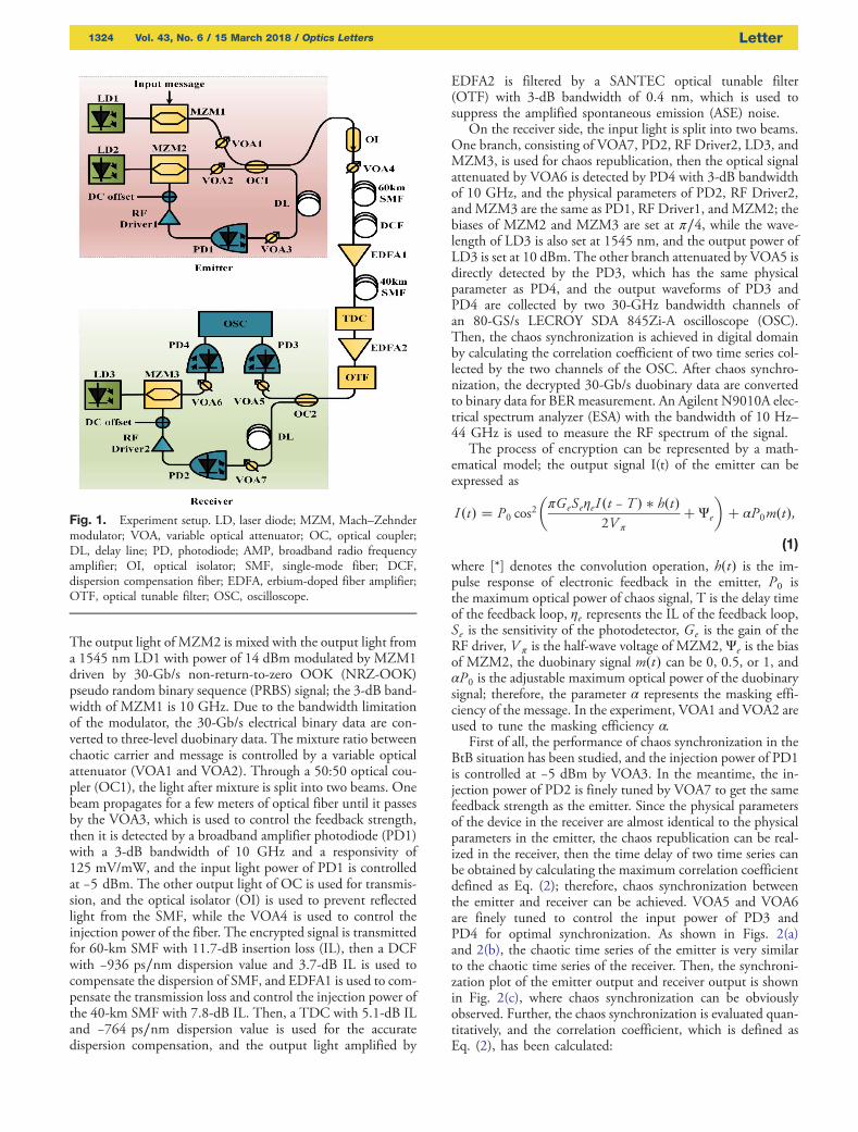
First of all, the performance of chaos synchronization in theBtB situation has been studied, and the injection power of PD1is controlled at −5 dBm by VOA3. In the meantime, the in-jection power of PD2 is finely tuned by VOA7 to get the samefeedback strength as the emitter. Since the physical parametersof the device in the receiver are almost identical to the physicalparameters in the emitter, the chaos republication can be real-ized in the receiver, then the time delay of two time series canbe obtained by calculating the maximum correlation coefficientdefined as Eq. (2); therefore, chaos synchronization betweenthe emitter and receiver can be achieved. VOA5 and VOA6are finely tuned to control the input power of PD3 andPD4 for optimal synchronization. As shown in Figs. 2(a)and 2(b), the chaotic time series of the emitter is very similarto the chaotic time series of the receiver. Then, the synchroni-zation plot of the emitter output and receiver output is shownin Fig. 2(c), where chaos synchronization can be obviouslyobserved. Further, the chaos synchronization is evaluated quan-titatively, and the correlation coefficient, which is defined asEq. (2), has been calculated:
Fig. 1. Experiment setup. LD, laser diode; MZM, Mach–Zehndermodulator; VOA, variable optical attenuator; OC, optical coupler;DL, delay line; PD, photodiode; AMP, broadband radio frequencyamplifier; OI, optical isolator; SMF, single-mode fiber; DCF,dispersion compensation fiber; EDFA, erbium-doped fiber amplifier;OTF, optical tunable filter; OSC, oscilloscope.
1324 Vol. 43, No. 6 / 15 March 2018 / Optics Letters Letter
C � h�x�t� − hx�t�i��y�t� − hy�t�i�iffiffiffiffiffiffiffiffiffiffiffiffiffiffiffiffiffiffiffiffiffiffiffiffiffiffiffiffiffiffiffiffiffiffiffiffiffiffiffiffiffiffiffiffiffiffiffiffiffiffiffiffiffiffiffiffiffiffiffiffiffiffih�x�t� − hx�t�i�2ih�y�t� − hy�t�i�2i
p ; (2)
where x�t� is the time trace of the emitter, y�t� is the time traceof the receiver, and h·i denotes average. The calculated corre-lation coefficient C is 96.44%. Also, The RF spectrum of thechaos signal is measured by ESA, as shown in Fig. 3(a), wherethe 3-dB bandwidth is about 10 GHz.
In order to generate the 30-Gb/s duobinary signal from the30-Gb/s NRZ-OOK signal by the electrical filtering effect ofthe system, the system end-to-end bandwidth has been mea-sured. First, in the BtB case, the electrical feedback loop inthe emitter was disconnected, and a KEYSIGHT PNANetwork Analyzer N5224A with 10 MHz–43.5 GHz was con-nected to the electrical port of MZM1 and the output of PD3.The S21 curve is shown in Fig. 3(b), and the 3-dB bandwidthof the system is about 9 GHz.
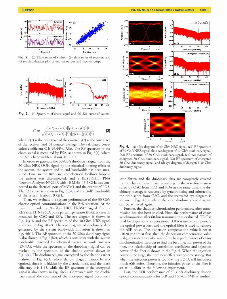
Then, we evaluate the system performance of the 30-Gb/schaotic optical communications in the BtB situation. At thetransmitter side, a 30-Gb/s NRZ PRBS15 signal from aKEYSIGHT N4960A pulse pattern generator (PPG) is directlymeasured by OSC and ESA. The eye diagram is shown inFig. 4(a1), and the RF spectrum of the 30-Gb/s NRZ signalis shown in Fig. 4(a2). The eye diagram of duobinary datagenerated by the system bandwidth limitation is shown inFig. 4(b1). The RF spectrum of the 30-Gb/s duobinary signalis also shown in Fig. 4(b2), which is consistent with the systembandwidth detected by electrical vector network analyzer(EVNA), while the spectrum of the duobinary signal can bemasked by the spectrum of the chaotic carrier shown inFig. 3(a). The duobinary signal encrypted by the chaotic carrieris shown in Fig. 4(c1), where the eye diagram cannot be rec-ognized, since it is hidden by the chaotic noise, and the maskefficiency α is 1.45, while the RF spectrum of the encryptedsignal is also shown in Fig. 4(c2). Compared with the duobi-nary signal, the spectrum of the encrypted signal becomes a
little flatter, and the duobinary data are completely coveredby the chaotic noise. Last, according to the waveforms mea-sured by OSC from PD3 and PD4 at the same time, the du-obinary message is recovered by synchronizing and subtractingthe time series from OSC, and the recovered eye diagram isshown in Fig. 4(d), where the clear duobinary eye diagramcan be achieved again.
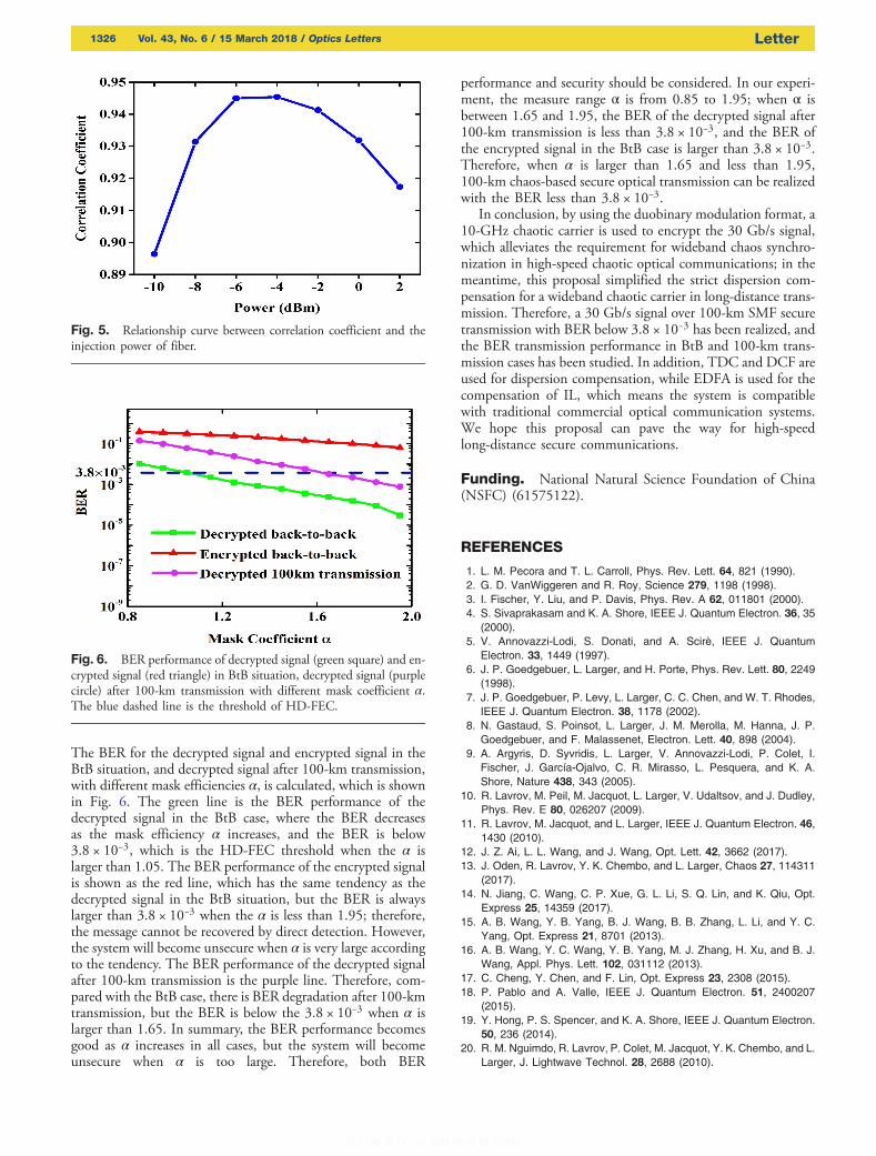
Further, the chaos synchronization performance after trans-mission has also been studied. First, the performance of chaossynchronization after 60-km transmission is evaluated. TDC isused for dispersion compensation, EDFA is used to compensatethe optical power loss, and the optical filter is used to removethe ASE noise. The dispersion compensation value is set at−1020 ps∕nm at first, then the dispersion compensation valueis slightly tuned to make sure of the best performance of chaossynchronization. In order to find the best injection power of thefiber, the relationship of correlation coefficient and injectionpower of the fiber is shown in the Fig. 5. When the injectionpower is too large, the nonlinear effect will become strong. Butwhen the injection power is too low, the EDFA will introducemuch ASE noise. Therefore, the injection power of the fiber isset at −4 dBm in the following experiment.
Last, the BER performance of 30 Gb/s duobinary chaoticoptical communications for BtB and 100-km SMF is studied.
Fig. 2. (a) Time series of emitter; (b) time series of receiver; and(c) synchronization plot of emitter output and receiver output.
Fig. 3. (a) Spectrum of chaos signal and (b) S21 curve of system.
Fig. 4. (a1) Eye diagram of 30-Gb/s NRZ signal, (a2) RF spectrumof 30-Gb/s NRZ signal, (b1) eye diagram of 30-Gb/s duobinary signal,(b2) RF spectrum of 30-Gb/s duobinary signal, (c1) eye diagram ofencrypted 30-Gb/s duobinary signal, (c2) RF spectrum of encrypted30-Gb/s duobinary signal, and (d) eye diagram of decrypted 30-Gb/sduobinary signal.
Letter Vol. 43, No. 6 / 15 March 2018 / Optics Letters 1325
The BER for the decrypted signal and encrypted signal in theBtB situation, and decrypted signal after 100-km transmission,with different mask efficiencies α, is calculated, which is shownin Fig. 6. The green line is the BER performance of thedecrypted signal in the BtB case, where the BER decreasesas the mask efficiency α increases, and the BER is below3.8 × 10−3, which is the HD-FEC threshold when the α islarger than 1.05. The BER performance of the encrypted signalis shown as the red line, which has the same tendency as thedecrypted signal in the BtB situation, but the BER is alwayslarger than 3.8 × 10⁻³ when the α is less than 1.95; therefore,the message cannot be recovered by direct detection. However,the system will become unsecure when α is very large accordingto the tendency. The BER performance of the decrypted signalafter 100-km transmission is the purple line. Therefore, com-pared with the BtB case, there is BER degradation after 100-kmtransmission, but the BER is below the 3.8 × 10⁻³ when α islarger than 1.65. In summary, the BER performance becomesgood as α increases in all cases, but the system will becomeunsecure when α is too large. Therefore, both BER
performance and security should be considered. In our experi-ment, the measure range α is from 0.85 to 1.95; when α isbetween 1.65 and 1.95, the BER of the decrypted signal after100-km transmission is less than 3.8 × 10⁻³, and the BER ofthe encrypted signal in the BtB case is larger than 3.8 × 10⁻³.Therefore, when α is larger than 1.65 and less than 1.95,100-km chaos-based secure optical transmission can be realizedwith the BER less than 3.8 × 10⁻³.
In conclusion, by using the duobinary modulation format, a10-GHz chaotic carrier is used to encrypt the 30 Gb/s signal,which alleviates the requirement for wideband chaos synchro-nization in high-speed chaotic optical communications; in themeantime, this proposal simplified the strict dispersion com-pensation for a wideband chaotic carrier in long-distance trans-mission. Therefore, a 30 Gb/s signal over 100-km SMF securetransmission with BER below 3.8 × 10⁻³ has been realized, andthe BER transmission performance in BtB and 100-km trans-mission cases has been studied. In addition, TDC and DCF areused for dispersion compensation, while EDFA is used for thecompensation of IL, which means the system is compatiblewith traditional commercial optical communication systems.We hope this proposal can pave the way for high-speedlong-distance secure communications.
Funding. National Natural Science Foundation of China(NSFC) (61575122).
REFERENCES
1. L. M. Pecora and T. L. Carroll, Phys. Rev. Lett. 64, 821 (1990).2. G. D. VanWiggeren and R. Roy, Science 279, 1198 (1998).3. I. Fischer, Y. Liu, and P. Davis, Phys. Rev. A 62, 011801 (2000).4. S. Sivaprakasam and K. A. Shore, IEEE J. Quantum Electron. 36, 35
(2000).5. V. Annovazzi-Lodi, S. Donati, and A. Scirè, IEEE J. Quantum
Electron. 33, 1449 (1997).6. J. P. Goedgebuer, L. Larger, and H. Porte, Phys. Rev. Lett. 80, 2249
(1998).7. J. P. Goedgebuer, P. Levy, L. Larger, C. C. Chen, and W. T. Rhodes,
IEEE J. Quantum Electron. 38, 1178 (2002).8. N. Gastaud, S. Poinsot, L. Larger, J. M. Merolla, M. Hanna, J. P.
Goedgebuer, and F. Malassenet, Electron. Lett. 40, 898 (2004).9. A. Argyris, D. Syvridis, L. Larger, V. Annovazzi-Lodi, P. Colet, I.
Fischer, J. García-Ojalvo, C. R. Mirasso, L. Pesquera, and K. A.Shore, Nature 438, 343 (2005).
10. R. Lavrov, M. Peil, M. Jacquot, L. Larger, V. Udaltsov, and J. Dudley,Phys. Rev. E 80, 026207 (2009).
11. R. Lavrov, M. Jacquot, and L. Larger, IEEE J. Quantum Electron. 46,1430 (2010).
12. J. Z. Ai, L. L. Wang, and J. Wang, Opt. Lett. 42, 3662 (2017).13. J. Oden, R. Lavrov, Y. K. Chembo, and L. Larger, Chaos 27, 114311
(2017).14. N. Jiang, C. Wang, C. P. Xue, G. L. Li, S. Q. Lin, and K. Qiu, Opt.
Express 25, 14359 (2017).15. A. B. Wang, Y. B. Yang, B. J. Wang, B. B. Zhang, L. Li, and Y. C.
Yang, Opt. Express 21, 8701 (2013).16. A. B. Wang, Y. C. Wang, Y. B. Yang, M. J. Zhang, H. Xu, and B. J.
Wang, Appl. Phys. Lett. 102, 031112 (2013).17. C. Cheng, Y. Chen, and F. Lin, Opt. Express 23, 2308 (2015).18. P. Pablo and A. Valle, IEEE J. Quantum Electron. 51, 2400207
(2015).19. Y. Hong, P. S. Spencer, and K. A. Shore, IEEE J. Quantum Electron.
50, 236 (2014).20. R. M. Nguimdo, R. Lavrov, P. Colet, M. Jacquot, Y. K. Chembo, and L.
Larger, J. Lightwave Technol. 28, 2688 (2010).
Fig. 5. Relationship curve between correlation coefficient and theinjection power of fiber.
Fig. 6. BER performance of decrypted signal (green square) and en-crypted signal (red triangle) in BtB situation, decrypted signal (purplecircle) after 100-km transmission with different mask coefficient α.The blue dashed line is the threshold of HD-FEC.
1326 Vol. 43, No. 6 / 15 March 2018 / Optics Letters Letter