Channel P2PRUNB Specification: comparison between ...
56
Power Matters IEEE802.3 4P Task Force Channel P2PRUNB Specification: comparison between specification alternatives September 2014 Yair Darshan Microsemi [email protected]
Transcript of Channel P2PRUNB Specification: comparison between ...

Power Matters
IEEE802.3 4P Task Force
Channel P2PRUNB Specification: comparison between specification alternatives
September 2014
Yair Darshan Microsemi

IEEE802.3bt, Channel P2PRUNB Specification: comparison between specification alternatives rev 001. Yair Darshan August 2014,
Supporters
2
David Hess / CORD DATA
Rick Frosch / Phihong
Dinh, Thuyen / Pulse
Christian Biea / ST
Fred Schindler / Seen Simply
Kousalya Balasubramanian / Cisco
IEEE802.3bt, Channel P2PRUNB Specification: comparison between specification alternatives rev 001. Yair Darshan August 2014,
Presenting the facts regarding specification alternatives based on last year work:
• Analysis
• Discussions
• Simulations
• Lab tests.
• 13 Adhoc meetings
• Many technical presentations
Terms:
• Option 1: Specification based on single worst case value as traditionally used in IEEE and TIA specifications.
• Option 2: Using equation form as function of channel parameters
• Other options addressed too.
Objectives
3

IEEE802.3bt, Channel P2PRUNB Specification: comparison between specification alternatives rev 001. Yair Darshan August 2014,
33.1.4.3 4-Pair Operation Channel Requirement for Pair to Pair Resistance Unbalance
4 pair operation requires the specification of resistance unbalance difference between each two pairs of the channel, is not greater than 200 100 milliohms or a resistance unbalance of 6% (TBD) 7.5% whichever is a greater unbalance. Resistance unbalance between the channel pairs is a measure of the difference of resistance of the common mode pairs of conductors used for power delivery. Channel pair to pair resistance unbalance is defined by equation 33-1.1:
33-1.1
Channel pair to pair resistance difference is defined by equation 33-1.2:
33.1.2
Where:
Rch_max is the sum of channel pair elements with highest common mode resistance.
Rch_min is the sum of channel pair elements with lowest common mode resistance.
Common mode resistance is the resistance of the two wires in a pair (including connectors), connected in parallel. Note: 7.5% is the worst case pair to pair resistance unbalance at 100 milliohms of channel pair to pair resistance difference. At 100m channel
length, the cable and connectors ensures 5.5% maximum channel pair to pair resistance unbalance.
• NOTE: The pair-to-pair resistance unbalance values are preliminary working numbers used for characterizing cabling while awaiting input from ISO/IEC SC25 (developing the second edition of ISO/IEC TR 29125) and TIA TR42 (developing a revision of TIA TSB-184). These groups have works in progress that are expected to include pair-to-pair resistance unbalance specifications suitable for reference.
Current Base Line Text approved on May 2014 with proposed updates.(Now we name it Option 1: Single value form for any unbalance parameter)
4
%100min_max_
min_max_ ×
+
−
chch
chch
RR
RR
min_max_ chch RR −
IEEE802.3bt, Channel P2PRUNB Specification: comparison between specification alternatives rev 001. Yair Darshan August 2014,
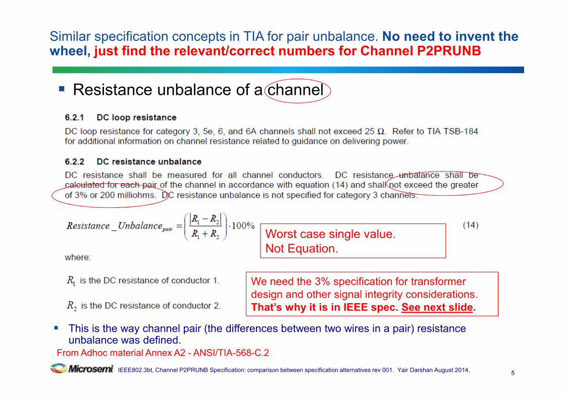
Resistance unbalance of a channel
Similar specification concepts in TIA for pair unbalance. No need to invent the wheel, just find the relevant/correct numbers for Channel P2PRUNB
5
We need the 3% specification for transformer
design and other signal integrity considerations.
That’s why it is in IEEE spec. See next slide.
From Adhoc material Annex A2 - ANSI/TIA-568-C.2
Worst case single value.
Not Equation.
This is the way channel pair (the differences between two wires in a pair) resistance unbalance was defined.

IEEE802.3bt, Channel P2PRUNB Specification: comparison between specification alternatives rev 001. Yair Darshan August 2014,
This is the way channel pair (the differences between two wires in a pair) resistance unbalance was defined.
Similar specification concepts in IEEE for pair unbalance. No need to invent the wheel.
6
From Adhoc material Annex A – IEEE802.3 standard
Worst case single value.
Not Equation!

IEEE802.3bt, Channel P2PRUNB Specification: comparison between specification alternatives rev 001. Yair Darshan August 2014,
Cable Pair unbalance Channel pair Unbalance Ratio Reference
2% 3% +50% IEEE3, TIA4
Cable P2P unbalance1 Channel pair Unbalance2
5% 7.5% +50% Proposed for
IEEE802.3bt
Channel vs. Cable specification.
Interesting comparison.
7
1. http://www.ieee802.org/3/4PPOE/public/nov13/darshan_01_1113.pdf
2. http://www.ieee802.org/3/bt/public/jul14/darshan_01_0714.pdf
3. IEEE802.3 clause 33.1.4.2
4. ANSI/TIA-568-C.2 clause 6.2.2.

IEEE802.3bt, Channel P2PRUNB Specification: comparison between specification alternatives rev 001. Yair Darshan August 2014,
Same reasons why we defined it for pair unbalance in IEEE specification (=3%).
• In addition to data integrity reasons, to allow data transformer design.
• Ibias=It*(1+Runb)/2=1.03*It/2. For PoE effect.
Now we have additional factor. The Channel P2PRUNB
• Transformer design will be depend on End to End C_P2PRUNB
• Ibias=It*(1+E2E_C_P2PRUNB)*Runb/4=Imax*Runb/2
• However End to End C_P2PRUNB will not be part of the spec!
• So we need to have the C_P2PRUNB to be part of the spec to evaluate the worst case point in the E2ECP2PRUNB which happens far below 100m.
• Other alternative is to define Imax however, C_P2PRUNB will be required for:
– Testing PSEs and PDs for meeting Imax, PSE and PD behavior at:
– Short channel (0.1 Ω or 7.5% which ever is greater). Channel lowest resistance is embedded in this definition
– 100m, 12.5Ω round loop for PSE/PD per existing requirements.
Conclusion: We need single worst case number for the channel. Otherwise we cannot design the transformer to be interoperable and cost effective for all system installations.
Why we need a definition for the channel in IEEE specification? (1)
8

IEEE802.3bt, Channel P2PRUNB Specification: comparison between specification alternatives rev 001. Yair Darshan August 2014,
Pair maximum current is function of channel, PSE and PD pair to pair resistance unbalance.
Once PSE PI and PD PI are defined, we need to generate channel specification that is:
• Simple
• Installation implementation independent specification
– Interoperable with all systems installations as regard to P2PRUNB
• Testable for all PSEs and PDs
– Based on worst case existing (and new) CABLES and CONNECTORS data in terms of their minimum resistance.
Conclusion:
• The solution for it is: single worst case value specification that can be updated later per statistical analysis or statistical survey of worst case channel pair to pair unbalance
Next slide, see the mathematical proof for the need of channel specification
Why we need a definition for the channel in IEEE specification? (2)
9

IEEE802.3bt, Channel P2PRUNB Specification: comparison between specification alternatives rev 001. Yair Darshan August 2014,
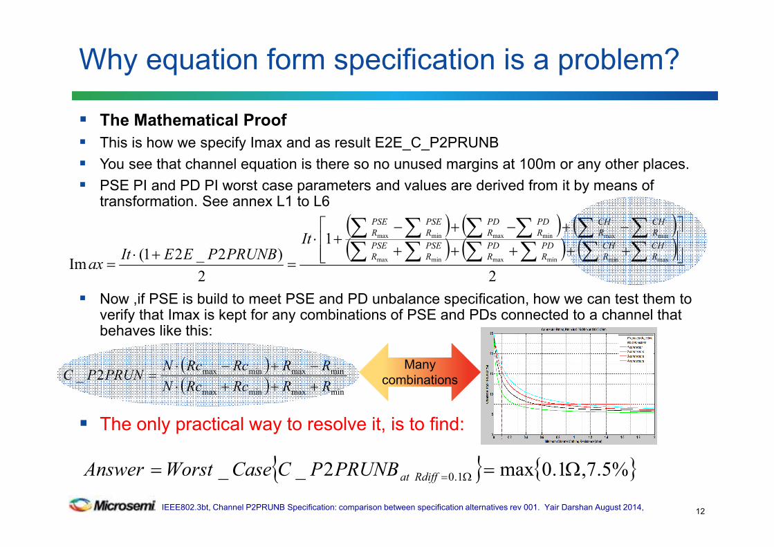
The Mathematical Proof
This is how we specify Imax and as result E2E_C_P2PRUNB
You see that channel equation is there so no unused margins at 100m or any other places.
PSE PI and PD PI worst case parameters and values are derived from it by means of transformation. See annex L1 to L6
Now ,if PSE is build to meet PSE and PD unbalance specification, how we can test them to verify that Imax is kept for any combinations of PSE and PDs connected to a channel that behaves like this:
The only practical way to resolve it, is to find:
Why we need a definition for the channel in IEEE specification? (3)
10
( ) ( ) ( )( ) ( ) ( )
2
1
2
)2_21(Im
maxminminmaxminmax
minmaxminmaxminmax
+++++
−+−+−+⋅
=+⋅
=∑ ∑∑∑∑∑
∑∑∑ ∑∑∑CH
R
CH
R
PD
R
PD
R
PSE
R
PSE
R
CH
R
CH
R
PD
R
PD
R
PSE
R
PSE
RIt
PRUNBPEEItax
( )( ) minmaxminmax
minmaxminmax2_RRRcRcN
RRRcRcNPRUNPC
+++⋅−+−⋅
=
%5.7,1.0max2__ 1.0 Ω== Ω=RdiffatPRUNBPCCaseWorstAnswer
Many
combinations

IEEE802.3bt, Channel P2PRUNB Specification: comparison between specification alternatives rev 001. Yair Darshan August 2014,
Equation AND use case based.
Single 7.5% max accurate worst case limit starting at Rdiff=0.1Ω.
5% is underestimation
Addresses realistic and non-realistic use cases
Use cases peaks creates a trend line presenting the optimum C_PWPRUNB of channel equation
No unused margins at short channel and long channels. E2ECP2PRUNB determine the current NOT the
channel specification
Why option 1 is the optimum accurate specification
11
6.75%
1. C_P2PRUNB peaks happen whenever we have more than 1 connector per meter (No peaks happen when we have at least 1 connector per 4m of channel length). This is good. Peaks belongs to unrealistic use cases located below Rdiff=0.1Ω.
2. At Rdiff=0.1Ω, P2PRUNB=7.5%.
2
6
BC
D
10
5 12
11
8
A
1514
25
%
≤7.5% <0.1 Ω
IEEE802.3bt, Channel P2PRUNB Specification: comparison between specification alternatives rev 001. Yair Darshan August 2014,
The Mathematical Proof
This is how we specify Imax and as result E2E_C_P2PRUNB
You see that channel equation is there so no unused margins at 100m or any other places.
PSE PI and PD PI worst case parameters and values are derived from it by means of transformation. See annex L1 to L6
Now ,if PSE is build to meet PSE and PD unbalance specification, how we can test them to verify that Imax is kept for any combinations of PSE and PDs connected to a channel that behaves like this:
The only practical way to resolve it, is to find:
Why equation form specification is a problem?
12
( ) ( ) ( )( ) ( ) ( )
2
1
2
)2_21(Im
maxminminmaxminmax
minmaxminmaxminmax
+++++
−+−+−+⋅
=+⋅
=∑ ∑∑∑∑∑
∑∑∑ ∑∑∑CH
R
CH
R
PD
R
PD
R
PSE
R
PSE
R
CH
R
CH
R
PD
R
PD
R
PSE
R
PSE
RIt
PRUNBPEEItax
( )( ) minmaxminmax
minmaxminmax2_RRRcRcN
RRRcRcNPRUNPC
+++⋅−+−⋅
=
%5.7,1.0max2__ 1.0 Ω== Ω=RdiffatPRUNBPCCaseWorstAnswer
Many
combinations

IEEE802.3bt, Channel P2PRUNB Specification: comparison between specification alternatives rev 001. Yair Darshan August 2014,
Equation is an implementation dependent specification
• We depend on channel length we don’t know it
• We need channel resistance wire size? we don’t know it
• So PSE and PD need to be designed for worst case unbalance. How designer will do it?
It has huge margins at short channels ~20m (using 4 connectors at 4m channel?)
We have bigger problems at short channels than at 100m
If we use “0.1Ω or 5% which ever is greater” it will be under estimation per the use case analysis
Why Equation Form is a problem
13
Ω++Ω+−
=032.0
08.02_
minmax
minmax
RR
RRPRUNPC
~17% with equation form (option 2) as
opposed to 7.5% in single worst case
value (option 1) due to using 4
connectors for all non-realistic and
realistic use cases.
0.1
( )( ) min_max_minmax
min_max_minmax
2_
cablecable
cablecable
RRRcRcN
RRRcRcN
PRUNBPChannel
+++⋅
−+−⋅=
=

IEEE802.3bt, Channel P2PRUNB Specification: comparison between specification alternatives rev 001. Yair Darshan August 2014,
Irrelevant question. Equation form can’t work so it is not an option.
• It is like comparing a feature between non compliant PD to a compliant PD.
OK we can’t use it. If we will use it what are the possible effects?
Answer: The following is the system equation that controls Imax
Due to the fact that the system equation above is using option 2 equation, there is zero margin in pair current and power at the PD.
If 7.5% flat will be used at the channel part of the system equation at 100m, the effect will be negligible. Why?
• PSE PI and PD PI unbalance>>channel unbalance at 100m
• Imax will happen at channel <100m. See numbers and simulation results on next slides.
• No value for equation form, only problems. No increase current or less power.
Do we have unused margins between single worst case value and equation form
14
( ) ( ) ( )( ) ( ) ( )
2
1
2
)2_21(Im
maxminminmaxminmax
minmaxminmaxminmax
+++++
−+−+−+⋅
=+⋅
=∑ ∑∑∑∑∑
∑∑∑ ∑∑∑CH
R
CH
R
PD
R
PD
R
PSE
R
PSE
R
CH
R
CH
R
PD
R
PD
R
PSE
R
PSE
RIt
PRUNBPEEItax
Option 1:
0.1Ω or 7.5% which ever is greater Option 2:
Equation form: Ω++Ω+−
=032.0
08.02_
minmax
minmax
RR
RRPRUNPC
OR

IEEE802.3bt, Channel P2PRUNB Specification: comparison between specification alternatives rev 001. Yair Darshan August 2014,
Any how, the incentive of the equation supporter is to benefit from the
5.5% at 100m instead of flat 7.5% or to reduce the 7.5% to lower number.
• The above is misunderstanding of the facts. It is not a real 2% margin.
• It was shown that the 2% difference is actually doesn’t exist.
– The channel equation is used in the system equation (E2ECP2PRUNB)
RESULTING WITH 0% unused margin
The channel spec. doesn't affect the end to end channel P2PRUNB.
• The cables and connectors are defined. They set the real behavior.
• You can’t build a channel with 7.5% at 100m if cables and connectors meet their specification.
The 7.5% is the worst case point at 0.1Ω that represents realistic use cases.
In order to have implementation independent spec we must have single point
worst case number and not equation which is implementation depended and its
output is not repeatable for all PSE – CHANNEL – PD combinations
A short summary of the facts shown at the adhoc presentations are
presented in the following slides.
Later it will be shown a fair way to reduce the 7.5% a bit lower.
Option 2: Equation form
15
IEEE802.3bt, Channel P2PRUNB Specification: comparison between specification alternatives rev 001. Yair Darshan August 2014,
There is only one correct equation form that describe the channel that we agreed that we cant
use. The following are examples for equation proposals or other specification forms that
found to be unusable. Moreover, no data shown to support them.
• July 2014 IEEE meeting: 5%+0.1Ω=Equation suggested at Minority report by Jeff Heath/LT.
• Adhoc meeting #11: Dave Dwelley suggested 5% OR 0.1Ω since the previous can’t work. This is similar
to the current base line concept but it is incorrect too, since it underestimate the actual behavior of the
use cases.
A correct equation form was presented by Yair (there is only one the physics) in his work
( May 2014, adhoc meeting #8, and July 2014 plenary, and explain that he chooses not to
use it (marked informative) as a specification due to a long list of problems.
http://www.ieee802.org/3/bt/public/jul14/darshan_01_0714.pdf
http://www.ieee802.org/3/bt/public/unbaladhoc/Comparison%20between%20proposed%20base%20line%20text%20and%20e
quation%20form%20and%20addressing%20FAQ%20rev%20002.pdf
Dave Dwelley presented that there is insignificant differences between equation form and
single number form especially if in the system we use the equaton channel so no unused
margins.
Checking other spec alternatives.Option 2: Equation form and others -1
16

IEEE802.3bt, Channel P2PRUNB Specification: comparison between specification alternatives rev 001. Yair Darshan August 2014,
"4P pair operation requires that the resistance unbalance between each set of pairs in the cabling and cordage shall be 5% or less. In addition, total pair-to-pair resistance difference due to any inline connectors shall not exceed 0.1ohm. The combination of these two unbalance terms gives the total resistance unbalance between the channel pairs used for power delivery. Channel pair to pair resistance unbalance is defined by...”
Response:
We agree that we cannot use the following equation due to
many reasons that are listed below.
Now if we lucky and we know how to generate the accurate
equation from the text above, we will get the following equation
that gives us no knowledge on worst case condition or any condition:
• In order to find the equation we need:
• We have N*(Rcmax-Rc_min)=0.1Ω, We have cable P2PRUNB=5%
• We don’t have Rcmax+Rcmin.
• We don’t have Rcable_min SO WE CANT COMPUTE Rcable_max
• What are the conditions that defines cable Rmin? Wire size, cable length etc.?
• So we don’t have equation. We don’t have nothing! • We don’t know nothing about worst case and how to test PSEs, PDs and design transformers
In addition:
We already agreed that there is zero differences between equation form (if we have all details) to single number form.
Now with text that try to describe equation, it even worsen due to the fact that now we will be depending on interpretations
of what is the equation. • We don’t control end user installation• How this text can be used to generate test set up that will be used by test houses and will end with the same results?• It is not clear what is the worst case number so how we can design our PSE to not exceed Imax? How we can design
our magnetics.• The single worst case number proposal per base line text doesn’t add margins since we agree to use equation at the
system level.
Equation form in a shape of text description -2
17
Ω++Ω+−
=032.0
08.02_
minmax
minmax
RR
RRPRUNPC
( )( ) min_max_minmax
min_max_minmax
2_
cablecable
cablecable
RRRcRcN
RRRcRcN
PRUNBPChannel
+++⋅
−+−⋅=
=

IEEE802.3bt, Channel P2PRUNB Specification: comparison between specification alternatives rev 001. Yair Darshan August 2014,
What if we break the 7.5% point to two or 3 parts for example:
• At Rdiff=0.1Ω, C_P2PRUNB=7.5%
• At TBD1 channel length: 6.5%
• At TBD2 up to 100m channel length: 5.5%
The same problem as in any equation: PSE or PD designer will need to design to the worst case anyway i.e. 7.5% so we gain nothing but confusion..
Why segmentation of Option 1 is a problem too?
18
6.75
%
2
6
B CD
1
0
512
11
8
A
15
14
25
%
<0.1 Ω

IEEE802.3bt, Channel P2PRUNB Specification: comparison between specification alternatives rev 001. Yair Darshan August 2014,
At Rdiff=0.1Ω, C_P2PRUNB=7.5% max.
At 100m C_P2PRUNB= 5.5% max.
The first will be used anyway for single worst case.
The 2nd set a limit cannot be used for worst case design at 100m but it can be used as good informative data point.
The original problem stays: It will create confusion as for what will be the channel P2PRUNB to be used for testing the PSE or PD?
The proposed solution:
• Use the 2nd part as informative note i.e.:
– Note: 7.5% is the worst case pair to pair resistance unbalance at 100 milliohms of channel pair to pair resistance difference. At 100m channel length, the cable and connectors resistance values ensures 5.5% maximum channel pair to pair resistance unbalance.
– Use statistical analysis and reduce the 7.5%. The simplest way.
What if we define the specification at two worst case points?
19

IEEE802.3bt, Channel P2PRUNB Specification: comparison between specification alternatives rev 001. Yair Darshan August 2014,
Q:
Cabling vendors will be confused and will design cables with 7.5% instead of 5% unbalance
Answers:
This is a channel spec. Not a cable specification. It is clear.
In the IEEE standard the channel pair unbalance is defined for 3% and yet cabling vendors design for 2% which is the cable spec.
Interesting to see that at worst case:• Cable pair unbalance =2% Channel pair unbalance=3% 50% ratio
• Cable P2P unbalance=5% (TBD) Channel P2P unbalance = 7.5% 50% ratio
Q&A1- Channel spec "confuse" cabling vendor
20

IEEE802.3bt, Channel P2PRUNB Specification: comparison between specification alternatives rev 001. Yair Darshan August 2014,
Q: We may loose 1W at the PD at 100m due to 2% perceived difference between
the two concepts . See http://www.ieee802.org/3/bt/public/unbaladhoc/dwelley_adhoc_082614b.pdf
Answers:
It is not correct. >1,000,000 systems gets 51W power (and more).
• No issues.
If maximum pair is limited to 600mA AND channel specification
(7.5%) will be used in the End to End C_P2PRUNB then Simulations
shows 0.5W max and not 1W.
So what are the sources of the differences between 1W to 0.5W?
– You need to use E2E_CP2PRUNB and not Channel P2PRUNB. PSE PI and PD
PI are missing. The transfer function from channel to system is <1 !!!.
– Constant power sink effect is not included when 100m channel with 0.09Ω/m.
– Equation should use Imax and not ILIM since at I max everything should work
but this is semantic since I understand your intention to mean Imax.
• But the actual power loss is ZERO. Why? See next slides:
Q&A2 – Less power at PD
21

IEEE802.3bt, Channel P2PRUNB Specification: comparison between specification alternatives rev 001. Yair Darshan August 2014,
Q: We may loose 1W at the PD at 100m due to 2% perceived difference
between the two concepts
• The actual power loss is ZERO.
• The channel specification is not determine the current at 100m. It is a worst
case number at <100m. The current is determined by actual behavior of the
cables and connectors at 100m which are specified controlled by channel
equation used by E2ECP2PRUNB.
In addition: We don’t need to limit pair current to 600mA!
• If P2PRUNB increases ,power loss on cable decreases, more power at the PD
• We can set Icut to any value we want per the current IEEE curve. Wide range
of flexibility we have.
• P2PRUNB after statistical analysis will be much better (>1M samples proof)
• We can keep the same Icut , ILIM with intelligent PSE and PD PI specifications
that are the major contributors to unbalance not at 100m!
Q&A2 – Less power at PD Cont.
22

IEEE802.3bt, Channel P2PRUNB Specification: comparison between specification alternatives rev 001. Yair Darshan August 2014,
Q: Does equation form creates interoperability issues?
A: Yes.
• If C_P2PRUNB EQUATION depends on:
– Channel length
– Its ABS min/max resistance
– Its wire size
• How we can design transformers? We must have one worst case limit.
• In the equation form, the worst case point is implementation dependent
of the channel connected to PSE and PD!
Same as we have 3% unbalance for a pair in the CHANNEL, we need
single worst case number 7.5%, for P2P in the CHANNEL.
Q&A3 – Interoperability
23

IEEE802.3bt, Channel P2PRUNB Specification: comparison between specification alternatives rev 001. Yair Darshan August 2014,
Q: Does 7.5% channel unbalance overestimates the cable unbalance (5%)?
Answers: NO.
If channel pair unbalance of 3% doesn’t overestimates the cable pair unbalance which is 2% (50% margin) then the answer is the same: NO.
It was shown previously that the C_P2PRUNB equation included at the E2ECP2PRUNB which affect the current zero unused margin.
EVEN if you use the channel P2PRUNB 7.5% spec as the channel equation in the E2E_C_P2PRUN you will get the following results:
AT 100m, The 2% margin will be overtaken by the PSE PI and PD PI which are>>5.5%
Example: With system that has E2ECP2PRUN=15% at 100m. Imax=659mA worst case! for 51W PD.
Now Channel unbalance at 100m increased from 5.5% to 7.5%. 2% increase.
The current increased to 668mA. Only 9mA difference =1.4% increase.
The effect on magnetics: 1.4%*3%/2=0.21% 0.21%*9mA=0.0189mA<<1mA.
Magnetic power loss: +2.8% don’t care.
The effect on power loss of the whole magnetic package: -0.2% (improvement).
Q&A4 – Unused margins, Effect on magnetics
24

IEEE802.3bt, Channel P2PRUNB Specification: comparison between specification alternatives rev 001. Yair Darshan August 2014,
Q: We saw that the proposed specification with 7.5% has negligible effect on End to End Channel Current Unbalance performance, transformers , PD available power etc. (See adhoc #11-#12 material and discussion).
What is the sure way reduce unbalance requirement e.g. 7.5% and stay with single worst case value?
A: The way to reduce the overall worse case P2PRUNB in the channel is to use statistical analysis so the 7.5% point that crosses the 0.1Ω point will be reduced.
Any kind of equation that is function of channel parameters or contains more then single maximum worst case value can't be a solution.
Q&A5 – Future improvements
25

IEEE802.3bt, Channel P2PRUNB Specification: comparison between specification alternatives rev 001. Yair Darshan August 2014,
Statistical analysis
Q&A5 – Future improvements Cont.
26
6.75%
2
6
B CD
10
512
11
8
A
15
14
25%
<0.1 Ω <7.5%
Worst case, use case analysis trend line
Proposed spec. Single worst case value.
Statistical Analysis TBD results, single worst case value.

IEEE802.3bt, Channel P2PRUNB Specification: comparison between specification alternatives rev 001. Yair Darshan August 2014,
Single worst case C_P2PRUN value (option 1) guarantees interoperability and channel implementation independent spec.
Equation form is used in the E2E_C_P2PRUNB which limits the maximum pair current and guarantees that actual performance is better than worst-case channel specification.
Cable P2PRUNB (5%) and connectors specifications guarantee that the actual channel behavior will be bellow the channel spec which is the upper limit possible.
Zero value in equation form. In addition: Interoperability issues: worst case points are function of system components PSE, PD and cabling installation details that are beyond our control.
The ONLY way to reduce single value 7.5% is to do statistical analysis and we know this from day one. So let’s continue with our plans and finish the channel P2P specifications without further delays.
Propose to continue with our roadmap i.e.:
Update the TBDs in May 2014 base line text: 7.5% and 0.1Ω numbers per the following slide.
Conclusions
27
IEEE802.3bt, Channel P2PRUNB Specification: comparison between specification alternatives rev 001. Yair Darshan August 2014,
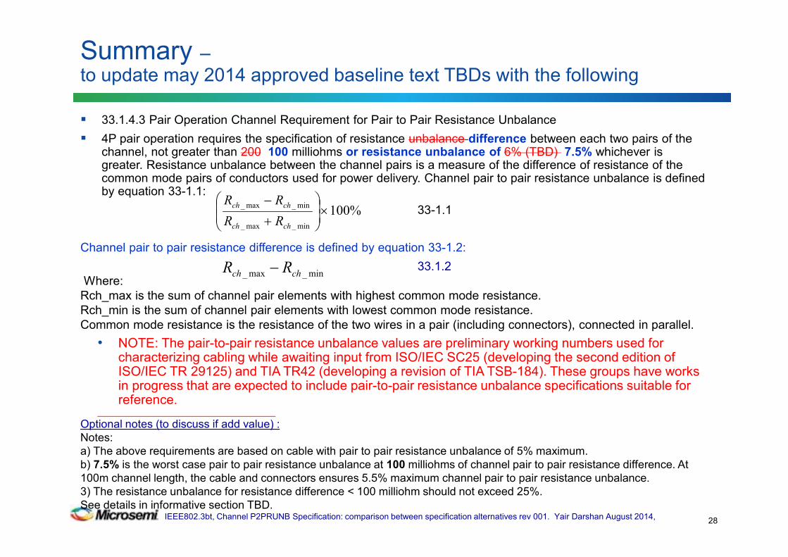
33.1.4.3 Pair Operation Channel Requirement for Pair to Pair Resistance Unbalance
4P pair operation requires the specification of resistance unbalance difference between each two pairs of the channel, not greater than 200 100 milliohms or resistance unbalance of 6% (TBD) 7.5% whichever is greater. Resistance unbalance between the channel pairs is a measure of the difference of resistance of the common mode pairs of conductors used for power delivery. Channel pair to pair resistance unbalance is defined by equation 33-1.1:
33-1.1
Channel pair to pair resistance difference is defined by equation 33-1.2:
33.1.2
Where:
Rch_max is the sum of channel pair elements with highest common mode resistance.
Rch_min is the sum of channel pair elements with lowest common mode resistance.
Common mode resistance is the resistance of the two wires in a pair (including connectors), connected in parallel.
• NOTE: The pair-to-pair resistance unbalance values are preliminary working numbers used for characterizing cabling while awaiting input from ISO/IEC SC25 (developing the second edition of ISO/IEC TR 29125) and TIA TR42 (developing a revision of TIA TSB-184). These groups have works in progress that are expected to include pair-to-pair resistance unbalance specifications suitable for reference.
_____________________________________________________________________
Optional notes (to discuss if add value) :
Notes:
a) The above requirements are based on cable with pair to pair resistance unbalance of 5% maximum.
b) 7.5% is the worst case pair to pair resistance unbalance at 100 milliohms of channel pair to pair resistance difference. At
100m channel length, the cable and connectors ensures 5.5% maximum channel pair to pair resistance unbalance.
3) The resistance unbalance for resistance difference < 100 milliohm should not exceed 25%.
See details in informative section TBD.
Summary –to update may 2014 approved baseline text TBDs with the following
28
%100min_max_
min_max_ ×
+
−
chch
chch
RR
RR
min_max_ chch RR −

IEEE802.3bt, Channel P2PRUNB Specification: comparison between specification alternatives rev 001. Yair Darshan August 2014,
Discussion
29
IEEE802.3bt, Channel P2PRUNB Specification: comparison between specification alternatives rev 001. Yair Darshan August 2014,
Backup Slides
30

IEEE802.3bt, Channel P2PRUNB Specification: comparison between specification alternatives rev 001. Yair Darshan August 2014,
The Channel Only. See Annex F for the entire system
31

IEEE802.3bt, Channel P2PRUNB Specification: comparison between specification alternatives rev 001. Yair Darshan August 2014,
Due to the fact that we cannot force the typical use case, other use cases, that exhibit high number of connectors per channel length, that are considered not typical or unrealistic ones, were analyzed to verify our sensitivity to such use cases.
The results will help us to verify if our channel spec is complete and robust. .
Adhoc proposed channel use cases
32

IEEE802.3bt, Channel P2PRUNB Specification: comparison between specification alternatives rev 001. Yair Darshan August 2014,
Channel P2P RUNB-Addressing TBDs
33
In May 2014 we vote for the following base line text highlighting the TBD areas.
33.1.4.3 Pair Operation Channel Requirement for Pair to Pair Resistance Unbalance
4P pair operation requires the specification of resistance unbalance between each two pairs of the channel, not greater than 200 milliohms or 6%(TBD) whichever is greater. Resistance unbalance between the channel pairs is a measure of the difference of resistance of the common mode pairs of conductors used for power delivery. Channel pair to pair resistance unbalance is defined by [..”
-------------------------------------------------------------------------------------
We need to address two numbers:
C_P2PRUNB=6%(TBD) and Resistance Difference=200milliOhm.

IEEE802.3bt, Channel P2PRUNB Specification: comparison between specification alternatives rev 001. Yair Darshan August 2014,
The 200milliohm in the channel base line text from May 2014 above should be 0.1Ω. Why?
Connector max Rdiff= 0.05Ω. 4 connectors is 4*0.05Ω=0.2Ω on each pair. As a result, a pair of pairs has two connectors in parallel, therefore 0.1Ω
• Connector maximum resistance is 0.2Ω and is not relevant to the discussion here which is pair to pair maximum resistance difference.
The value of channel maximum Rdiff
34
Source: Yair Darshan.
Confirmed by Wayne Larsen

IEEE802.3bt, Channel P2PRUNB Specification: comparison between specification alternatives rev 001. Yair Darshan August 2014,
Presentation Flow
35
Step Analyzing the proposed use cases
1 a) Compare analysis results of proposed use case A,B,C and D
to Channel P2PRUNB=6%
b) Checking other use cases near the proposed use cases to check the
Channel P2PRUNB sensitivity to deviation from the proposed use cases.
2 Understanding the reasons and rationale behind the results from different
angle and as function of channel parameters
3 Checking if P2PRUNB and Rdiff is sufficient to specify the channel for any
use case.
4 Checking if Rdiff alone is sufficient to define the channel
5 Conclusions and information obtained from this work regarding:
-Channel
-Future work on PSE and PD PI.

IEEE802.3bt, Channel P2PRUNB Specification: comparison between specification alternatives rev 001. Yair Darshan August 2014,
Channel Component Data used in this work
36
# Component Value Reference
1 Patch Cord 0.0926Ω/m Adhoc for worst case analysis
(Cable with AWG#24 wire)
0.14Ω/m Adhoc, Standard.
2 Horizontal Cable CAT6A AWG23 1. Adhoc
2. See Annex G1, G2, G3, E1
3. See Slide 27 (was Annex K20)
3 Connector Rmin=0.03Ω
Rdiff_max=0.02Ω
Rmax=0.06Ω
1. Rdiff (TBD) : Adhoc
2. Rmin, Rmax: Adhoc
3. See Annex G1, G2, G3, E1-E6
4. See Slide 27 (was Annex K20)
Questions such:
1. Why not to use 0.098 Ω/m as per standard etc. are answered in annexes above. If more data is needed, please addressee
this question to the reflector.
2. Why not use Rmax=0.2Ω and Rdiff_max=0.05Ω for connector? Answer: It is maximum values and for worst case analysis
we need minimum values for Rmax and Rmin and a maximum practical values for Rdiff.
3. The conclusions that was derived from the analyzed topics in this work topics, will not change dramatically for other
practical data number sets.
Table 1

IEEE802.3bt, Channel P2PRUNB Specification: comparison between specification alternatives rev 001. Yair Darshan August 2014,
From previous ad-hoc meetings decisions: To check use cases A, B, C and D per the table below for Channel P2PRUNB specification derivation.
Additional use cases were added (total 16 at a time) after running the simulations in order to find Channel P2PRUN hidden peaks for specification sensitivity analysis.
Table below provides a summary. See details next slides.
Use cases to be checked during analysis
37
Use
case
Connectors Cordage[m] Cable[m] Max. Channel P2PRUN
A 0 ≥0.15 0 5% (equal to Cable P2PRUNB)
0 0 ≥0.15
B 2 1 3 9.2% (Covered by the Rdiff requirement)
C 4 8 15 6.47%
D 4 10 90 5.45%
2-4,
6-8
10
1
2
4
See curve next slide.
Considered as
unrealistic use cases
10% - 20% (Covered by the Rdiff requirement)

IEEE802.3bt, Channel P2PRUNB Specification: comparison between specification alternatives rev 001. Yair Darshan August 2014,
Use case analysis results and proposed objective
38
• A,B,C and D are considered as Typical use cases. The other
use cases are used for discovering peaks that should be
covered by the specification as well (the Rdiff=0.1Ω max.)
• Use case B is above 7% however it is
covered by the Rdiff. See next slides.
• Use Case C is above 6%. Change to 7%.
A
B
CD
Since we can not force only realistic use cases, the question is how we ensure that channel
will not fail P2PRUNB compliance tests when tested with different use cases than A,B,C and D?

IEEE802.3bt, Channel P2PRUNB Specification: comparison between specification alternatives rev 001. Yair Darshan August 2014,
Channel P2PRUNB vs. Use case parameters
39
A B C D
When cable resistance starts to dominate over the
connectors, Channel P2PRUNB decreases.

IEEE802.3bt, Channel P2PRUNB Specification: comparison between specification alternatives rev 001. Yair Darshan August 2014,
Connector P2PRunb=100%*(50-30)/(50+30)=25%
Cable P2PRUNB=5%.
Channel P2PRUNB: See 5 curves with different connector numbers
Channel P2PRUNB vs. Cable resistance and connectors
40
Checking how the minimum cabling resistance
(P2PRUNB=5%) reduces the connector (P2PRUNB=25%).
Channel P2PRUNB is function of absolute value of the
component resistances and not only resistance
differences! See the math in annex L1-L8.
Informative part
(Round Loop Cable resistance)
Worst case equation form (see slide 35 for details) :

IEEE802.3bt, Channel P2PRUNB Specification: comparison between specification alternatives rev 001. Yair Darshan August 2014,
Unrealistic use cases are now concentrated in minimum cabling resistance region.
0.7Ω minimum cabling resistance for a channel with 4 connectors, is required to reduce all
CP2PRUNB peaks to below 7% (L1+L2~=18m total per use case # 12 in the table above).
We may not need to require minimum channel length of 18m however it is nice to know
that above 18m the channel is acting as ballast resistor to the PSE and PD PI.
Use case analysis results – Sanity Check -1 Zooming on the peaks by Changing X axis for Cabling Minimum resistance
41
2
A
6
B
C
D
10
5
Cable minimum resistance correspond to :Rmin=[(1-0.05)/(1+0.05)]*(L1[m]*0.09262Ω/m+L2*0.0792Ω/m)
L1 and L2 are per the use case table above.
1312
16
11 Informative part
2%
7%
7.5%
5.5%

IEEE802.3bt, Channel P2PRUNB Specification: comparison between specification alternatives rev 001. Yair Darshan August 2014,
The realistic use cases A,B,C, and D looks good. B is below Resistance Difference=0.1Ω
Rdiff is increased as cable total resistance is increased. As a result Rdiff alone cannot be
used for specifying the channel we must have the C_P2PRUNB[%] too as expected.
See Annex L7-L8 for details.
Use case analysis results – Sanity Check -2 Zooming on the peaks by Changing X axis for Channel Resistance Difference
42
1. C_P2PRUNB peaks happen whenever we have more than 1 connector per meter (No peaks happen when we have at least 1 connector per 4m of channel length) or connectors with very short cables. This is good since the peaks are below Rdiff=0.1Ω.
2. These peaks are considered as unrealistic use cases.3. At Rdiff=0.1Ω, P2PRUNB=7.5%. Change to 7.5%.
2
6
B C
D
10
5 12
11
<0.1 Ω < 7%
8
≤7.5% <0.1 Ω
A6% 1514
dx
7.5%
25%
5.5%6.75%
0.117

IEEE802.3bt, Channel P2PRUNB Specification: comparison between specification alternatives rev 001. Yair Darshan August 2014,
We can see that the high C_P2PRUNB peaks happen when:
• There are more than 1 connector per 1m. No peaks obtain when there is ~≤1 connector per 4m of channel length (ratio of 0.22 to 0.25) and/or:
• The cables and patch cords are short and exhibit low resistance compared to total connector resistance
• The above use cases are considered "unrealistic" ones, covered by Rdiff=0.1Ω (was 0.2 Ω).
Use Case B is considered to be realistic, and exceeds the initial proposed 7% but it is covered by Rdiff=0.1Ω (was 0.2 Ω) requirement.
– It has 2 connectors over 4m channel which is 2/4=0.5 ratio which is way different that the general behavior above of 0.25 ratio. So all is good
We saw that:
• Per the Rdiff curve: we can select the specification numbers between:
• (a) Rdiff=0.1Ω, P2PRUNB=7.5%. (b) Rdiff=0.117Ω, P2PRUNB=7%. (c) Rdiff=0.1Ω, P2PRUNB=7%.
• Option (a) is the correct one from worst case analysis point of view.
• Option (b) is not matching the maximum P2P Rdiff per connector standards =0.1 Ω
• Option (c) is possible if counting on the fact that it is worst case analysis and we have design margins for small deviation of 0.5%/0.025Ω. which may be the best optimized cost effective set of parameters.
We may need informative section that says that for 4P operation, it is recommended to use a channel that has ≤1 connector per meter (maximum 4 connectors per standard). Anyway, unrealistic use cases are covered by Rdiff part in the spec.
Conclusions regarding Channel Unbalance Requirements -1
43

IEEE802.3bt, Channel P2PRUNB Specification: comparison between specification alternatives rev 001. Yair Darshan August 2014,
We agree in ad-hoc straw poll to define single number per any unbalance parameter e.g. 7.5% or 0.1Ω which ever is
greater in the channel base line proposal.
This concept is channel implementation independent which is inline with our objectives and simple to test for compliance.
The 7.5% at 100m vs. actual worst case number is at 5.5% at 100m looks like we have wasted 2% margin which is
incorrect due to the fact that the end to end channel P2P unbalance equation do use the channel equation so there is no
2% margin.
Even if we do use the channel proposed specification in the end to end equation, the 2% difference at 100m will be only
9mA increase on maximum pair current (from 659mA to 668mA which is 1.4% ) which is negligible. The effect on
transformer bias current will be even lower <200uA.
We could use equation that represents a curve to specify the channel P2PRUNB limits that tracks the curve in slide 15 so
at 100m we can get 5.5% instead of 7.5%.
The problems with using equation form:
(a) Equation makes the channel use case implementation depended
as opposed to the single number proposal. Since it depends in channel
construction (Cordage, Cables, connectors) to address all use cases.
(b ) we can simplifying it by selecting N=4 (see curve slide 14) and then it will became
even with higher margins at short channel (since 4 connectors will be used even
in unrealistic use cases e.g. 1m channel, increasing the P2PRUN margins, bring
us back to square 1 and it is still implementation dependent of cable combinations and resistance!
(c) The 2% difference between proposals at 100m is negligible in system level were unbalance is 15% - 20% at 100m and 25-
50% at short channel so the 2% at the channel at 100m only, is 0.21% at the transformer bias (1.4%*3%/2) and maximum
of 2%*3%/2=3% < 200uA for PD Type 3.
(d ) the above equation form increase more unbalance margins at short channel where it counts more.
(e) The simplified equation form is not addressing the 0.1 Ω point that addresses connectors resistance per the existing
TIE/EIA standard.
Conclusions regarding Channel Unbalance Requirements -2
44
( ) ( )minminmaxmax
minminmaxmax2RcNRRcNR
RcNRRcNRPRUNBCP
⋅++⋅+⋅+−⋅+
=
( )( ) 32.0
08.02
minmax
minmax
+++−
=RR
RRPRUNBCP
IEEE802.3bt, Channel P2PRUNB Specification: comparison between specification alternatives rev 001. Yair Darshan August 2014,
4P operation with minimum cable resistance help us:
(a) It will reduce some of the burden on PD PI and PSE PI
(b) It helps to reduce overall End to End Channel P2P RUNB and as a
result will reduce the maximum current over the pair with lowest
end to end resistance.
– The implication of the above is equivalent to minimum cable length.
This work shows clearly (by analytical proof and simulations) the following facts:
Only Resistance Difference Requirement for Channel specifications (Rdiff=|Rmax-Rmin|)
is mathematically and practically insufficient. See L1 –L8 for analytical derivation. This
requirement leads to clear interoperability issues. See L7 and L8. In channel, in particular, it
will contradict cable 5% P2PRUNB maximum limit. So we need at least both Rdiff and
P2PRUNB parameters for the channel as we have already in the base line text. Moreover
inexplicitly, for channel Rdif≤0.1Ω , P2PRUNB is bounded by the connector P2PRUNB
(25% per the data used in this work).
Conclusions regarding Channel Unbalance Requirements -3
45
IEEE802.3bt, Channel P2PRUNB Specification: comparison between specification alternatives rev 001. Yair Darshan August 2014,
The proposed unbalanced parameter values for the base line text are:
• Channel P2PRUNB max.: 7.5% (option a) or 7% (option c)
• Resistance Difference max: 0.1Ω
– (P2PRUNB for Rdiff≤ 0.1Ω is bounded by Connectors actual Rmin, Rmax values i.e.
25% in our analysis. Theoretically it can be higher and it will be bounded by system
unbalanced parameters)
Adhoc use cases proposals covers:
• Realistic use cases with short cables and long cables
• "unrealistic" use cases with short and long cables as well that we
actually cannot control or limit their use.
• It is worst case analysis, therefore contain inherent margins
• It is complete.
Summary
46

IEEE802.3bt, Channel P2PRUNB Specification: comparison between specification alternatives rev 001. Yair Darshan August 2014,
Update baseline text approved on IEEE802.3 May 2014 meeting to:
33.1.4.3 Pair Operation Channel Requirement for Pair to Pair Resistance Unbalance
4P pair operation requires the specification of resistance unbalance between each two pairs of the channel, not greater than 200 100 milliohms or 6%(TBD) 7.5% whichever is greater. Resistance unbalance between the channel pairs is a measure of the difference of resistance of the common mode pairs of conductors used for power delivery. Channel pair to pair resistance unbalance is defined by [..”
___________________________________________________________
Notes:
1. 7% is the cost effective choice per the conclusions slides.
2. 7.5% is the accurate solution.
Group to discuss.
Proposed update to Channel base line text
47
IEEE802.3bt, Channel P2PRUNB Specification: comparison between specification alternatives rev 001. Yair Darshan August 2014,
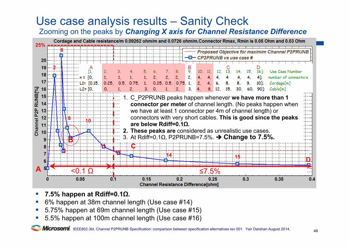
7.5% happen at Rdiff=0.1Ω.
6% happen at 38m channel length (Use case #14)
5.75% happen at 69m channel length (Use case #15)
5.5% happen at 100m channel length (Use case #16)
Use case analysis results – Sanity Check Zooming on the peaks by Changing X axis for Channel Resistance Difference
48
1. C_P2PRUNB peaks happen whenever we have more than 1 connector per meter of channel length. (No peaks happen when we have at least 1 connector per 4m of channel length) or connectors with very short cables. This is good since the peaks are below Rdiff=0.1Ω.
2. These peaks are considered as unrealistic use cases.3. At Rdiff=0.1Ω, P2PRUNB=7.5%. Change to 7.5%.
2
6
BC
D
10
5 12
11
8
≤7.5% <0.1 ΩA
1514
25%
IEEE802.3bt, Channel P2PRUNB Specification: comparison between specification alternatives rev 001. Yair Darshan August 2014,
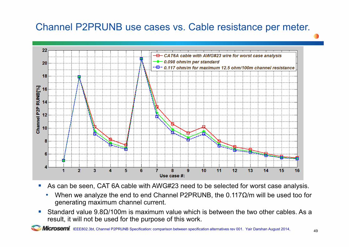
As can be seen, CAT 6A cable with AWG#23 need to be selected for worst case analysis.
• When we analyze the end to end Channel P2PRUNB, the 0.117Ω/m will be used too for generating maximum channel current.
Standard value 9.8Ω/100m is maximum value which is between the two other cables. As a result, it will not be used for the purpose of this work.
Channel P2PRUNB use cases vs. Cable resistance per meter.
49
IEEE802.3bt, Channel P2PRUNB Specification: comparison between specification alternatives rev 001. Yair Darshan August 2014,
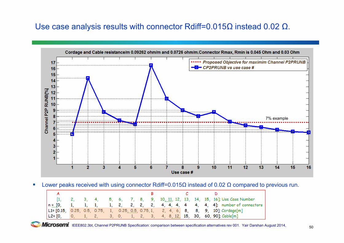
Lower peaks received with using connector Rdiff=0.015Ω instead of 0.02 Ω compared to previous run.
Use case analysis results with connector Rdiff=0.015Ω instead 0.02 Ω.
50
7% example

IEEE802.3bt, Channel P2PRUNB Specification: comparison between specification alternatives rev 001. Yair Darshan August 2014,
This use case is unlikely to happen although it represent connector Rmax and Rdiff maximum values per standard while we are looking for minimum values for worst case analysis.
Peaks are lower than Rmax=0.05Ω and Rdiff=0.02Ω .
See more effective view when It will require higher Rdiff e.g. 0.2 instead of 0.1 to cover all use cases including use case B which is considered to be realistic one.
Use case analysis results with connector Rmax=0.2Ω Rdiff=0.05Ω -1
51
7.5% example

IEEE802.3bt, Channel P2PRUNB Specification: comparison between specification alternatives rev 001. Yair Darshan August 2014,
Confirming that using connector maximum standard numbers contradicts P2P Rdiff=0.1Ω. It generates higher peaks above Rdiff=0.1Ω and requires ~10.5% C_P2PRUNB definition instead of 7.5% at Rdiff=0.1Ω which is highly unlikely to happen per connector data and process evaluation when converting process parameters (mean, sigma etc.) of Rmax=0.2Ω Rdiff=0.05Ω to actual worst case minimum/maximum/Rdiff of connectors used in this work 0.05/0.2 0.02/0.06. See worst case data base)
Use case analysis results with connector Rmax=0.2Ω Rdiff=0.05Ω -2C_P2PRUNB vs Rdiff
52

IEEE802.3bt, Channel P2PRUNB Specification: comparison between specification alternatives rev 001. Yair Darshan August 2014,
With 7.5% C_P2PRUNB limits.
Channel P2PRUNB vs. Cable resistance and connectors
53
IEEE802.3bt, Channel P2PRUNB Specification: comparison between specification alternatives rev 001. Yair Darshan August 2014,
( )( ) minmaxminmax
minmaxminmax2_RRRcRcN
RRRcRcNPRUNPChannel
+++⋅−+−⋅
==α
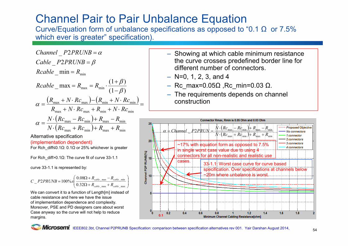
33-1.1: Worst case curve for curve based
specification. Over specifications at channels below
~20m where unbalance is worst.
0.1
~17% with equation form as opposed to 7.5%
in single worst case value due to using 4
connectors for all non-realistic and realistic use
cases.
Channel Pair to Pair Unbalance Equation Curve/Equation form of unbalance specifications as opposed to “0.1 Ω or 7.5% which ever is greater” specification).
54
( ) ( )
( )( ) minmaxminmax
minmaxminmax
minminmaxmax
minminmaxmax
minmax
min
)(1
)(1max_
min_
2_
2_
RRRcRcN
RRRcRcN
RcNRRcNR
RcNRRcNR
RRRcable
RRcable
PRUNBPCable
PRUNBPChannel
+++⋅−+−⋅
=
=⋅++⋅+⋅+−⋅+
=
−+
⋅==
=
=
=
α
α
ββ
βα – Showing at which cable minimum resistance
the curve crosses predefined border line for different number of connectors.
– N=0, 1, 2, 3, and 4
– Rc_max=0.05Ω ,Rc_min=0.03 Ω.
– The requirements depends on channel construction
Alternative specification
(implementation dependent)For Rch_diff≤0.1Ω: 0.1Ω or 25% whichever is greater
For Rch_diff>0.1Ω: The curve fit of curve 33-1.1
curve 33-1.1 is represented by:
We can convert it to a function of Length[m] instead of
cable resistance and here we have the issue
of implementation dependence and complexity.
Moreover, PSE and PD designers care about worst
Case anyway so the curve will not help to reduce
margins.
++Ω
−+Ω=
max_max_
min_max_
32.0
08.0%1002_
cablecable
cablecable
RR
RRxPRUNBPC
IEEE802.3bt, Channel P2PRUNB Specification: comparison between specification alternatives rev 001. Yair Darshan August 2014,
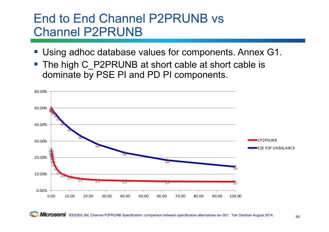
Using adhoc database values for components. Annex G1.
The high C_P2PRUNB at short cable at short cable is dominate by PSE PI and PD PI components.
End to End Channel P2PRUNB vsChannel P2PRUNB
55

IEEE802.3bt, Channel P2PRUNB Specification: comparison between specification alternatives rev 001. Yair Darshan August 2014,
Using adhoc database values for components. Annex G1.
The high C_P2PRUNB at short cable at short cable is dominate by PSE PI and PD PI components.
Maximum pair current
56