
Challenges and pitfalls of time constrained hydraulic projects
10
INTERNATIONAL CONFERENCE FLUID POWER 2021 CONFERENCE PROCEEDINGS D. Lovrec & V. Tič (eds.) Challenges and pitfalls of time constrained hydraulic projects TADEJ TAŠNER & KRISTIAN LES Abstract Almost all projects nowadays are fast paced as all industries are trying to shorten time to market and hydraulics is no exception. In order to compete in such environments all the processes in the company from engineering throughout production have to be streamlined, so they are able to effectively follow the ever-changing project requirements. Moreover, increasing lead-times and disrupted supply chains due to pandemic also influence the workflow, as components may not arrive in time. This article addresses all of the above-mentioned problems on a real world hydraulic project – a hydraulic drive of a forklift. It presents the evolution of hydraulic schematic, hydraulic manifold and control algorithms all the way from the first draft to the latest version. Keywords: • hydraulics • production • manifold • forklift • time to market • CORRESPONDENCE ADDRESS: Tadej Tašner, HAWE Hidravlični sistemi d.o.o., Ob Dragi 7, SI-3220 Štore, Slovenia. Kristian Les, HAWE Hidravlika d.o.o., Ob Dragi 7, SI-3220 Štore, Slovenia, e-mail: [email protected]. DOI https://doi.org/10.18690/978-961-286-513-9.23 ISBN 978-961-286-513-9 Dostopno na: http://press.um.si
Transcript of Challenges and pitfalls of time constrained hydraulic projects
INTERNATIONAL CONFERENCE FLUID POWER 2021 CONFERENCE PROCEEDINGS D. Lovrec & V. Tič (eds.)
Challenges and pitfalls of time constrained hydraulic projects
TADEJ TAŠNER & KRISTIAN LES
Abstract Almost all projects nowadays are fast paced as all industries are trying to shorten time to market and hydraulics is no exception. In order to compete in such environments all the processes in the company from engineering throughout production have to be streamlined, so they are able to effectively follow the ever-changing project requirements. Moreover, increasing lead-times and disrupted supply chains due to pandemic also influence the workflow, as components may not arrive in time. This article addresses all of the above-mentioned problems on a real world hydraulic project – a hydraulic drive of a forklift. It presents the evolution of hydraulic schematic, hydraulic manifold and control algorithms all the way from the first draft to the latest version. Keywords: • hydraulics • production • manifold • forklift • time to market •
CORRESPONDENCE ADDRESS: Tadej Tašner, HAWE Hidravlični sistemi d.o.o., Ob Dragi 7, SI-3220 Štore, Slovenia. Kristian Les, HAWE Hidravlika d.o.o., Ob Dragi 7, SI-3220 Štore, Slovenia, e-mail: [email protected]. DOI https://doi.org/10.18690/978-961-286-513-9.23 ISBN 978-961-286-513-9 Dostopno na: http://press.um.si

276 INTERNATIONAL CONFERENCE FLUID POWER 2021: CONFERENCE PROCEEDINGS.
1 Introduction Nowadays, competitive pressures, dynamic information, and new technologies drive changes in markets. It is crucial that companies respond to these changes. It is often the first to field a new product that captures market share and profits. Time to market defines the period from the conception of a new idea to the release of a product to the marketplace. Time to market varies widely by what is sold: product type, complexity, and industry. A typical time to market for a pharmaceutical is ten years, while a consumer social app could be conceptualized, researched, designed, prototyped, and launched in less than a year [1]. Table 1: Time to market by industry [1]
Industry Time to Market Range (Years) Energy 7-23
Aerospace & Defence 3-22 Healthcare & Pharma 9-19
Industrials 3-7 Automobile 3-5
Semiconductor 1-5 (2 year clock) Consumer Goods 1-5
Mobile Phones 1-3 (3 year clock) Technology 0.5-5
Hydraulic systems are normally subsystems of industrial and mobile applications, but often also fit into technology group, which has relatively short time to market, as seen in Table 1. In order to shorten time to market, our customers, who build our power packs into their products parallelize as much tasks as possible. Therefore, it is not possible to thoroughly test your product on the real application, which can sometimes lead to problems. In order to handle such rapidly changing projects, internal processes of the company have to be very flexible. Firstly, there has to be free engineering capacity, that when a change request is received someone can start working on it immediately. The engineering work should be backed with software tools that enable fast redesigns. Fast transfer to production is possible by using mostly

T. Tašner & Kristian Les: Challenges and Pitfalls of Time Constrained Hydraulic Projects 277
internal standard components pool that are normally in stock. Moreover, there has to be as little internal bureaucracy as possible in order to be able to change all the required documents as quickly as possible and propagate all the changes through the ERP system to purchasing and production [2]. Finally yet importantly, you need flexible and competent (local) suppliers, which are able to follow you at such a fast pace [3]. All of the measures listed above base on the part of lean production methodology, which applies to individual or small series production [4]. This article describes the whole lifecycle of hydraulic project all the way from project specification to finished hydraulic system, which is commissioned into customer’s end product – in our case a self-driving forklift. 2 Project Specification Our power pack lifts the load on the driverless forklifts or forklift automated guided vehicles (AGVs).
Figure 1: Forklift AGV Amadeus Classic and free space for the power pack [5].
278 INTERNATIONAL CONFERENCE FLUID POWER 2021: CONFERENCE PROCEEDINGS.
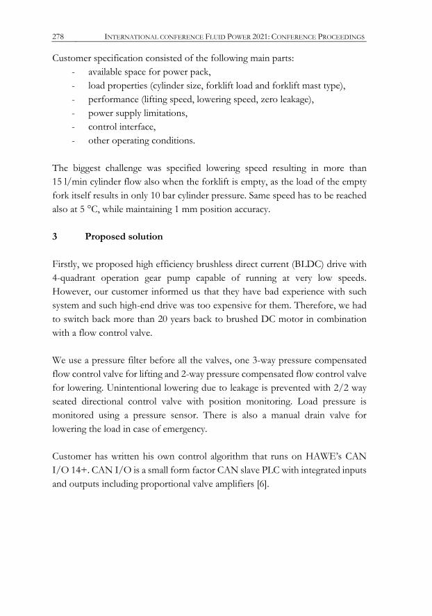
Customer specification consisted of the following main parts: - available space for power pack, - load properties (cylinder size, forklift load and forklift mast type), - performance (lifting speed, lowering speed, zero leakage), - power supply limitations, - control interface, - other operating conditions.
The biggest challenge was specified lowering speed resulting in more than 15 l/min cylinder flow also when the forklift is empty, as the load of the empty fork itself results in only 10 bar cylinder pressure. Same speed has to be reached also at 5 °C, while maintaining 1 mm position accuracy. 3 Proposed solution Firstly, we proposed high efficiency brushless direct current (BLDC) drive with 4-quadrant operation gear pump capable of running at very low speeds. However, our customer informed us that they have bad experience with such system and such high-end drive was too expensive for them. Therefore, we had to switch back more than 20 years back to brushed DC motor in combination with a flow control valve. We use a pressure filter before all the valves, one 3-way pressure compensated flow control valve for lifting and 2-way pressure compensated flow control valve for lowering. Unintentional lowering due to leakage is prevented with 2/2 way seated directional control valve with position monitoring. Load pressure is monitored using a pressure sensor. There is also a manual drain valve for lowering the load in case of emergency. Customer has written his own control algorithm that runs on HAWE’s CAN I/O 14+. CAN I/O is a small form factor CAN slave PLC with integrated inputs and outputs including proportional valve amplifiers [6].

T. Tašner & Kristian Les: Challenges and Pitfalls of Time Constrained Hydraulic Projects 279
4 Test procedure We received a bare forklift mast for testing. For proof of concept pipe mount manifolds for each included component were connected using flexible hoses. Figure 2 shows the test setup. All the components have been tested with different load and speed combinations. The critical part was lowering speed, especially at low temperatures. Results of measured lowering speeds are therefore presented in the next paragraph.
Figure 2: Proof of concept test setup.
We have tested with VG 22 at 24 °C (44 cSt) oil to minimize valve losses and simulated VG 22 oil at 10 °C (96 cSt) using VG 46 oil at 24 °C (105 cSt). All results are displayed in Figure 3, where warm colors represent empty forklift mast with different oils and blue represents loaded forklift mast. It can be seen that we can reach linear (green) flow versus current relationship in our target flow range, that is between 0 and 15 l/min. Cylinder losses, pressure losses in the piping and losses in the flow control valve itself limit higher flow as shown on the right side of the graph (600 mA and up), where curves don’t align any more. That means that not enough load pressure is available to reach the flow set by the flow control valve.

280 INTERNATIONAL CONFERENCE FLUID POWER 2021: CONFERENCE PROCEEDINGS.
Figure 3: Initial test results for 2-way flow control valve used for lowering.
5 Commissioning results After the tests, we designed first version of the manifold that we fit onto a standard compact power pack. Customer himself commissioned power packs at his facility. Soon after the first tests, we received a complaint that the unit is too loud. We thought that it was impossible, as it did not happen at our facility. After a more detailed investigation, we found out that the noise was coming from the oscillating lifting flow control valve at low flows 0-20 % and from 25-100 % loads. The reason why we did not experience the issue is the connection between the power pack and the forklift mast. We used a 4 m long flexible hose and they used a 1 m long rigid pipe.
0,0 l/min
5,0 l/min
10,0 l/min
15,0 l/min
20,0 l/min
25,0 l/min
30,0 l/min
0 mA 200 mA 400 mA 600 mA 800 mA 1000 mA
flow vs. valve currentat different load pressures and temperatures
11,7 bar VG22 20,1 bar VG22
linear part 11,7 bar VG46

T. Tašner & Kristian Les: Challenges and Pitfalls of Time Constrained Hydraulic Projects 281
Figure 4: Initial test results for 2-way flow control valve used for lowering. 5.1 Fixing the problem Because the noise was too loud for the machine to be sent to the end customer, we had to immediately find a solution for the problem. As one of the HAWE subsidiaries manufactures the 3-way valve, we included the design team of the valve for further investigation. They concluded that the valve is meant for systems with different dynamic behaviour mainly with lower inertia; therefore, the dampening in the valve was too small. In order to increase the dampening, the valve should undergo a major change, which would not be completed in time. The noise could be attenuated by using a different spring and metering orifice, but the dampening of the control piston of the valve itself could not be easily increased, so the noise could not be eliminated. Therefore we proposed a new control concept to the customer. We eliminated the 3-way flow control valve for lifting and now lifting is controlled by letting excess flow with flow control valve for lowering into tank. Control algorithm now compensates pump flow variation with pressure, although the variation is quite significant due to brushed DC motors rpm decrease for increasing load . To be able to retrofit all the already shipped units, we prepared a plug for the 3-way flow control valve that plugs the tank line of the valve cavity.

282 INTERNATIONAL CONFERENCE FLUID POWER 2021: CONFERENCE PROCEEDINGS.
6 Project and changes flow The biggest challenge of the project was that there was no prototype order, as the customer’s time to market is very short. The following bullets sum up the order and engineering flow of the project and Figure 5 shows the evolution of the manifold:
- quote and proof of concept made - order for first series received - engineering completed & manufacturing started (initial manifold) - available space specification changed - manifold redesigned (optimized manifold) - further orders received & manufacturing started - first series shipped & commissioned - noise present further tests 3-way flow control valve eliminated - manifold redesigned (one flow control valve) - retrofit plug for all existing systems designed…
Figure 5: Manifold evolution – initial, optimized, one flow control valve.
State of the art digital design and production system enables us to quickly respond to the necessary changes. The Vault PDM system integrates fast version control for all of the design files, but it works especially well with Inventor, which paired with MD Tools add-in offers quick and intuitive manifold design. One

T. Tašner & Kristian Les: Challenges and Pitfalls of Time Constrained Hydraulic Projects 283
advantage of the correctly maintained 3D model library is ability to export bill of material of the power pack directly from Inventor. The bill of material is then semi-automatically synced with our ERP system, which automatically maintains stock levels for all of our standard components. Customer order creates a demand for all materials on the bill of material, which purchasing department buys based on current stock levels. However, tailored components such as manifolds cannot be purchased like ordinary components. Therefore, we have competitive local manifold suppliers that are able to handle small quantities in short times to keep up with our demand. Having local suppliers for such components is for us very important, as they can respond to potential problems on very short notice. With such workflow, we are able to handle projects such as these even during the pandemic, which increased lead times for many products. 7 Conclusion This article presented how to achieve short time-to-market even for small series and individual production with minimal impact on product cost and effective employee utilization. References [1] Carter, J. (2016). Time to Market: What it is, why it’s important, and five ways to reduce it.
https://www.tcgen.com/time-to-market [2] Hou, J., Su, C., Zhu, L., & Wang, W. (2008, August). Integration of the CAD/PDM/ERP
system based on collaborative design. 2008 ISECS International Colloquium on Computing, Communication, Control, and Management (Vol. 1, pp. 561-566). IEEE.
[3] Kojun, H. (2010). Outsourcing versus in-house production: the case of product differentiation with cost uncertainty. Seoul Journal of Economics, 23
[4] Mascitelli, R. (2007). The lean product development guidebook: everything your design team needs to improve efficiency and slash time-to-market. Technology Perspectives
[5] DS Automotion. Amadeus Classic Datasheet. Available: https://www.dsautomotion.com/fileadmin/userdaten/downloadbereich/datenblaetter/en/DS-AUTOMOTION-AMADEUS-EN.pdf
[6] HAWE (2021). CAN-IO valve controller – Product Documentation. https://downloads.hawe.com/7/8/D7845-IO_14-en.pdf

284 INTERNATIONAL CONFERENCE FLUID POWER 2021: CONFERENCE PROCEEDINGS.