Ch09 Notes
22
10/2/2015 1 Iron Carbide Phase Diagram Figure 9.6
-
Upload
adam-redmond -
Category
Documents
-
view
296 -
download
1
description
Notes for IUPUI ME 344
Transcript of Ch09 Notes

10/2/2015
1
Iron Carbide Phase Diagram
Figure 9.6

10/2/2015
2

10/2/2015
3
Creating Pearlite
Figure 9.7
Figure 9.8
After W. F. Smith, “The Structure and Properties of Engineering Alloys,” 2nd ed.,McGraw-Hill, 1981, p.8
Hypoeutectoid Plain Carbon Steel
Figure 9.9 Figure 9.10
Pearlite
After W. F. Smith, “The Structure and Properties of Engineering Alloys,” 2nd ed.,McGraw-Hill, 1981, p.10

10/2/2015
4
Hypereutectoid Plain Carbon Steel
Figure 9.11
After W. F. Smith, “The Structure and Properties of Engineering Alloys,” 2nd ed.,McGraw-Hill, 1981, p.12.
Proeutectoid Cementite (white)
Crystal Structure
Figure 9.17Figure 9.19
After E. R. Parker and V. F. Zackay Strong and Ductile Steels, Sci.Am.,November 1968, p.36; Copyright by Scientific American Inc; all rights reserved
AusteniteFCC
Slightly distorted
MartensiteBCC
Distorted (long in c)BCC- BC Tetragonal
Alpha FerriteBCC <0.2%C
Undistorted

10/2/2015
5
Microstructure of Fe – C Martensites
Figure 9.13
After A. R. Marder and G. Krauss, as presented in “Hardenebility Concepts with Applications to Steel,” AIME, 1978, p. 238.
Bainite
Figure 9.24
After H. E. McGannon(ed.), “The Making Shaping and Treating of Steel,” 9th ed., United States Steel Corp., 1971
Hot quenched 550-350 Hot quenched 350 - 250
10/2/2015
6
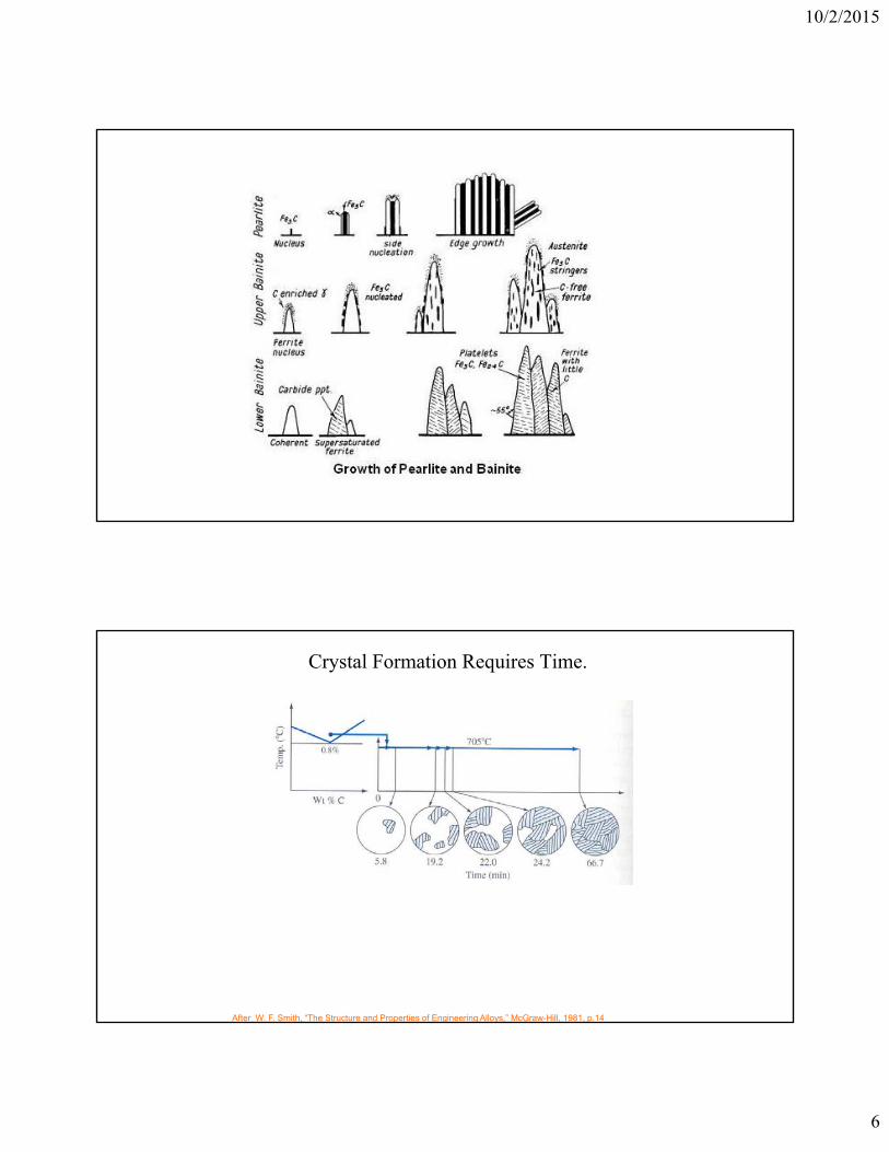
Crystal Formation Requires Time.
After W. F. Smith, “The Structure and Properties of Engineering Alloys,” McGraw-Hill, 1981, p.14

10/2/2015
7
Isothermal Transformation (IT)Diagram
Figure 9.22
After W. F. Smith, “The Structure and Properties of Engineering Alloys,” McGraw-Hill, 1981, p.14

10/2/2015
8
IT Diagrams for Noneutectoid Steels
Figure 9.25
After R. A. Grange, V. E. Lambert, and J. J. Harrington, Trans, ASM, 51:377(1959)

10/2/2015
9
Continuous Cooling-Transformation Diagram
Figure 9.26
After R. A. Grange and J. M. Kiefer, “Alloying Elements in Steel,” ASM 2nd ed., 1966, p.254.
Continuous Cooling-Transformation Diagram
Figure 9.27
After R. A. Grange and J. M. Kiefer, “Alloying Elements in Steel,” ASM 2nd ed., 1966, p.254.

10/2/2015
10
Heat Treatments
Annealing
Normalizing
Quenching
Tempering
Austenitizing

10/2/2015
11
Tempering of Plain Carbon Steel
Tempering Temperature
Below 200 C200 – 700 0C400 – 700 0C
Structure
Epsilon CarbideCementite (rod-like)Cementite (Spheroidite)
Figure 9.31
From “ Suiting the heat Treatment to the job,” United States Steel Corp., 1968, p.34.
Spheroidite – sphere like cementite particlesmost ductile – high energy productionsince keep at 700C for 30 hours or moreresults in softer steel than full anneal
Effects of Tempering
Figure 9.32
After JE. C. Bain, and H. W. Paxton, “Alloying Elements in Steel, “ 2nd ed., American Society for Metals, 1996 p.38.

10/2/2015
12
Classification
Classification of Alloy Steels
• First two digits: Principle alloying element.
• Last two digits: % of carbon.
Source: “Alooy Steel: Semifinished; Hot-Rolled and Cold-Finished Bars,” American Iron and Steel Institute, 1970.

10/2/2015
13
Hardenability
Weldability
Machineability
In General Choose between:
1. Load Bearing member – yield strength & toughness
2. Wear application – 60HRC on surface with required thickness
3. Through hardening (C > 0.3%)
4. High-strength, low-alloy – weldability and structural uses
Typical ranges in alloy steels (%) Principal effects
Aluminum <2 Aids nitriding Restricts grain growth
Adds machinabilityReduces weldability and ductility
Increases resistance to corrosion and oxidation Increases hardenabilityIncreases high-temperature strengthCan combine with carbon to form hard, wear-
resistant microconstituents
Sulfur <0.5
Chromium 0.3–4
spheric corrosion resistance
Increases hardenability Promotes an austenitic structureCombines with sulfur to reduce its adverse
effects
Manganese 0.3–2
tant microconstituents
Nickel 0.3–5 Promotes an austenitic structure
Increases hardenabilityCopper 0.2–0.5 Increases toughness
Promotes tenacious oxide film to aid atmo-
Silicon 0.2–2.5 Removes oxygen in steel making Improves toughnessIncreases hardenability
Molybdenum 0.1–0.5 Promotes grain refinement Increases hardenabilityImproves high-temperature strength
Vanadium 0.1–0.3 Promotes grain refinement Increases hardenabilityWill combine with carbon to form wear-resis-

10/2/2015
14
Mechanical Properties of Low Alloy Steels
4820
Table 9.6
Treatment E (Gpa)
Yield (Mpa)
Ultimate
Elongation
Microstruct
1 Normalized 205 475 793 22.7% Fine Pearlite
2 Annealed 830 C 11C/hr to 650C then air cooled
3 Oil quenched from 845 with 540 C temper
4 Oil quench from 845 with 595 C temper
5 Oil quench from 845 with 650 C temper
5140 Steel

10/2/2015
15
Aluminum

10/2/2015
16
Effects of Aging on Strength
Figure 9.43

10/2/2015
17
Copper
Stainless Steel

10/2/2015
18
Cast Iron
White Cast iron
Iron Carbide
Pearlite
Figure 9.59
Courtesy of central Foundry
10/2/2015
19
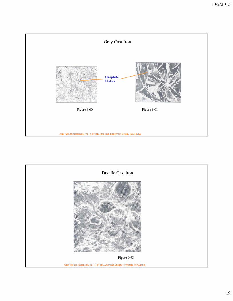
Gray Cast Iron
GraphiteFlakes
Figure 9.60 Figure 9.61
After “Metals Handbook,” vol. 7, 8th ed., American Society for Metals, 1972, p.82.
Ductile Cast iron
Figure 9.63
After “Metals Handbook,” vol. 7, 8th ed., American Society for Metals, 1972, p.88.

10/2/2015
20
Malleable Cast Iron
Figure 9.65
After “Metals Handbook,” vol. 7, 8th ed., American Society for Metals, 1972, p.95.
Magnesium Alloys

10/2/2015
21
Titanium Alloys
Nickel Alloys
Alnico (aluminium, cobalt; used in magnets)Alumel (manganese, aluminium, silicon)Chromel (chromium)Cupronickel (bronze, copper)Ferronickel (iron)German silver (copper, zinc)Hastelloy (molybdenum, chromium, sometimes tungsten)Inconel (chromium, iron)Monel metal (copper, iron, manganese)Nichrome (chromium)Nickel-carbon (carbon)Nicrosil (chromium, silicon, magnesium)Nisil (silicon)Nitinol (titanium, shape memory alloy)

10/2/2015
22
Shape Memory Effect
Heated(Austenite)
Cooled(Martensite)
Deformed(Martensite)
Heated(Austenite)
NiTi
NiTi
Amorphous Metals
crystalline Amorphous