CH08 Routing Power and Signal Cables 8-1 Cisco TelePresence System 3000 OL-14521-01 8 Routing Power...
24
CHAPTER 8-1 Cisco TelePresence System 3000 OL-14521-01 8 Routing Power and Signal Cables Revised: October 31, 2012, OL-14521-01 Parts List Caution Do not power on the PDUs and auxiliary control unit until you connect and route all the cables. Key Part Description Part Number Qty Ctn Notes 1 Power distribution units 74-4787-01 4 1 2 Speaker cable 37-0849-01 3 1 3 8 m DVI-to-VGA + audio cable 37-0848-01 1 1 4 6 m video cable 37-0854-01 1 1 5 3 m (black) Cat6 Ethernet cable 37-0877-01 5 1 6 10 m Cat6 Ethernet cable, blue 37-0901-01 2 1 7 7 m power cord 37-xxxx-xx 1 10 See “Region- and Country-Specific Equipment” for specific part numbers. 8 3 m Jumper cord 37-0833-01 9 1 9 2 m Jumper cord 37-0852-01 1 1 Used for projector. 10 3 m Video-to-DVI cable 37-0853-01 3 1 11 Cable identification stickers 51-4582-01 3 1 12 Cable ties 51-4536-01 75 1 13 Cable tie holders 51-0609-01 75 1 14 Ferrite Core 36-0244-01 12 1 15 Not used Projector-to-Auxiliary Control Unit (DSUB to 8-P MINI DIN) cable 37-0980-01 1 19 Packaged with Auxiliary Control unit Microphone extension cords Included with 74-4743-xx 3 1 Included in Microphone kit
Transcript of CH08 Routing Power and Signal Cables 8-1 Cisco TelePresence System 3000 OL-14521-01 8 Routing Power...

OL-14521-01
C H A P T E R 8
Routing Power and Signal CablesRevised: October 31, 2012, OL-14521-01
Parts List
Caution Do not power on the PDUs and auxiliary control unit until you connect and route all the cables.
Key Part Description Part Number Qty Ctn Notes
1 Power distribution units 74-4787-01 4 1
2 Speaker cable 37-0849-01 3 1
3 8 m DVI-to-VGA + audio cable 37-0848-01 1 1
4 6 m video cable 37-0854-01 1 1
5 3 m (black) Cat6 Ethernet cable 37-0877-01 5 1
6 10 m Cat6 Ethernet cable, blue 37-0901-01 2 1
7 7 m power cord 37-xxxx-xx 1 10 See “Region- and Country-Specific Equipment” for specific part numbers.
8 3 m Jumper cord 37-0833-01 9 1
9 2 m Jumper cord 37-0852-01 1 1 Used for projector.
10 3 m Video-to-DVI cable 37-0853-01 3 1
11 Cable identification stickers 51-4582-01 3 1
12 Cable ties 51-4536-01 75 1
13 Cable tie holders 51-0609-01 75 1
14 Ferrite Core 36-0244-01 12 1
15 Not used
Projector-to-Auxiliary Control Unit (DSUB to 8-P MINI DIN) cable
37-0980-01 1 19 Packaged with Auxiliary Control unit
Microphone extension cords Included with 74-4743-xx
3 1 Included in Microphone kit
8-1Cisco TelePresence System 3000
Chapter 8 Routing Power and Signal Cables Power Requirements for the Cisco TelePresence 3000
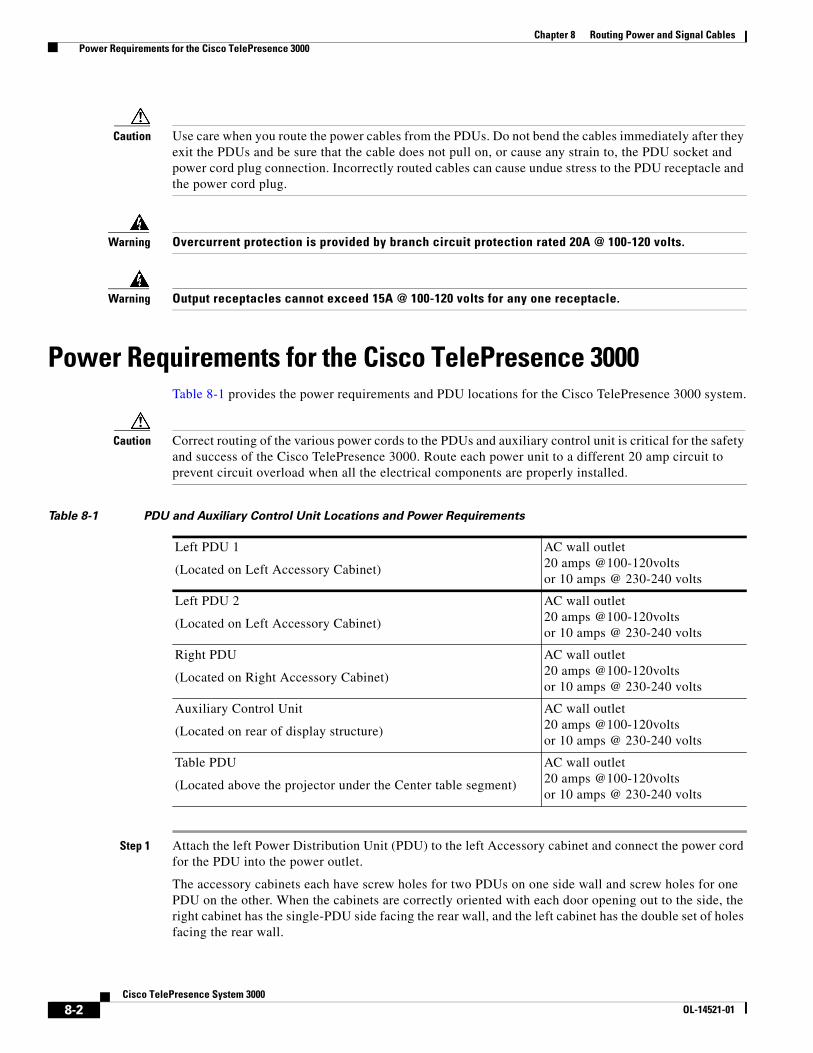
Caution Use care when you route the power cables from the PDUs. Do not bend the cables immediately after they exit the PDUs and be sure that the cable does not pull on, or cause any strain to, the PDU socket and power cord plug connection. Incorrectly routed cables can cause undue stress to the PDU receptacle and the power cord plug.
Warning Overcurrent protection is provided by branch circuit protection rated 20A @ 100-120 volts.
Warning Output receptacles cannot exceed 15A @ 100-120 volts for any one receptacle.
Power Requirements for the Cisco TelePresence 3000Table 8-1 provides the power requirements and PDU locations for the Cisco TelePresence 3000 system.
Caution Correct routing of the various power cords to the PDUs and auxiliary control unit is critical for the safety and success of the Cisco TelePresence 3000. Route each power unit to a different 20 amp circuit to prevent circuit overload when all the electrical components are properly installed.
Step 1 Attach the left Power Distribution Unit (PDU) to the left Accessory cabinet and connect the power cord for the PDU into the power outlet.
The accessory cabinets each have screw holes for two PDUs on one side wall and screw holes for one PDU on the other. When the cabinets are correctly oriented with each door opening out to the side, the right cabinet has the single-PDU side facing the rear wall, and the left cabinet has the double set of holes facing the rear wall.
Table 8-1 PDU and Auxiliary Control Unit Locations and Power Requirements
Left PDU 1
(Located on Left Accessory Cabinet)
AC wall outlet20 amps @100-120voltsor 10 amps @ 230-240 volts
Left PDU 2
(Located on Left Accessory Cabinet)
AC wall outlet20 amps @100-120voltsor 10 amps @ 230-240 volts
Right PDU
(Located on Right Accessory Cabinet)
AC wall outlet20 amps @100-120voltsor 10 amps @ 230-240 volts
Auxiliary Control Unit
(Located on rear of display structure)
AC wall outlet20 amps @100-120voltsor 10 amps @ 230-240 volts
Table PDU
(Located above the projector under the Center table segment)
AC wall outlet20 amps @100-120voltsor 10 amps @ 230-240 volts
8-2Cisco TelePresence System 3000
OL-14521-01

Chapter 8 Routing Power and Signal Cables Power Requirements for the Cisco TelePresence 3000
Figure 8-1 PDU installation to left accessory cabinet
Step 2 Attach the right PDU to the right Accessory cabinet and connect the power cord for the PDU into the power outlet.
2011
82
1
8-3Cisco TelePresence System 3000
OL-14521-01

Chapter 8 Routing Power and Signal Cables Power Requirements for the Cisco TelePresence 3000
Figure 8-2 Right-side PDU installation to right accessory cabinet
Step 3 Attach the center PDU to the center privacy panel and connect the power cord for the PDU into the power outlet.
1
2011
83
8-4Cisco TelePresence System 3000
OL-14521-01

Chapter 8 Routing Power and Signal Cables Power Requirements for the Cisco TelePresence 3000
Figure 8-3 Table assembly PDU attachment to the center Privacy panel
Note The PDU power cable should extend from the right side.
1
2011
84
8-5Cisco TelePresence System 3000
OL-14521-01

Chapter 8 Routing Power and Signal Cables Power Requirements for the Cisco TelePresence 3000
Step 4 Route the power cables for the table leg foam bumper I/O modules and the projector.
Figure 8-4 Routing Power Cables for I/O Modules and Projector
Note The six jumper cords from the I/O modules in the table legs route to the center PDU.
Tip Before plugging the Table leg jumper cords into the Table PDU, label each one. For example, Outer Left Power, Inner Right Power.
2012
04
TelePresence
3DEF
6MNO
9WXYZ
#
2ABC
5JKL
8TUV
0OPER
1
4GHI
7PQRS
CISCO IP PHONE7970
Table Leg Power
Projector Power
8
9
8-6Cisco TelePresence System 3000
OL-14521-01
Chapter 8 Routing Power and Signal Cables Power Requirements for the Cisco TelePresence 3000
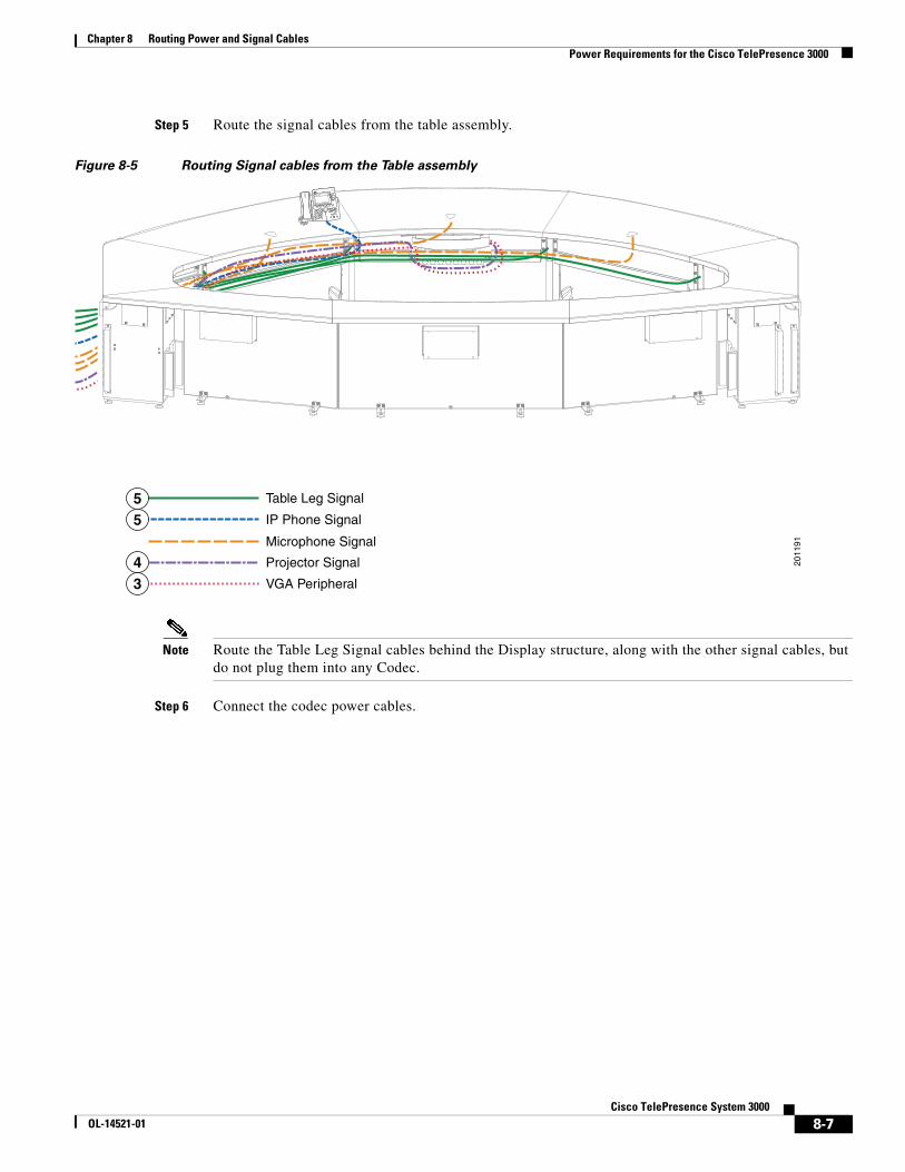
Step 5 Route the signal cables from the table assembly.
Figure 8-5 Routing Signal cables from the Table assembly
Note Route the Table Leg Signal cables behind the Display structure, along with the other signal cables, but do not plug them into any Codec.
Step 6 Connect the codec power cables.
2011
91
TelePresence
3DEF
6MNO
9WXYZ
#
2ABC
5JKL
8TUV
0OPER
1
4GHI
7PQRS
CISCO IP PHONE7970
Table Leg Signal
IP Phone Signal
Microphone Signal
Projector Signal
VGA Peripheral
55
43
8-7Cisco TelePresence System 3000
OL-14521-01

Chapter 8 Routing Power and Signal Cables Power Requirements for the Cisco TelePresence 3000
Figure 8-6 Routing the Codec Power Cables
Step 7 Connect the Cisco Unified IP Phone, VGA peripheral, and projector HD video cables.
Note The VGA Peripheral cable is the free-hanging cable resting in the VGA module attached to the center Table segment.
Note If you encounter any problems with the HD Video cable that runs between the projector and the codec, order the part number CTS-CAB-HDMI-HDMI as a replacement.
Power
2041
67
8-8Cisco TelePresence System 3000
OL-14521-01

Chapter 8 Routing Power and Signal Cables Power Requirements for the Cisco TelePresence 3000
Figure 8-7 Cabling the Cisco Unified IP Phone, DVI-to-VGA, and Projector HD Video Cables
Step 8 Connect the microphones to the microphone cables; then, connect the microphone cables to the codec and audio/video extension unit.
Caution Perform the following steps to prevent damage from electrostatic discharge (ESD) to the microphone, audio/video extension unit, or codec:
a. Discharge each microphone cable by touching the metal cable-connector to the codec or audio/video extension unit cable as shown in Figure 8-8.
b. Hold the cable connector to the codec or audio/video extension unit cable for 3 seconds.
IP Phone Signal
VGA Peripheral
Projector HD Video to Codec 2041
68
TelePresence
3DEF
6MNO
9WXYZ
#
2ABC
5JKL
8TUV
0OPER
1
4GHI
7PQRS
CISCO IP PHONE7970
642
8-9Cisco TelePresence System 3000
OL-14521-01

Chapter 8 Routing Power and Signal Cables Power Requirements for the Cisco TelePresence 3000
c. Immediately connect the microphone to the codec or audio/video extension unit using the diagram in Figure 8-8.
Figure 8-8 Discharging ESD from the Microphone Cables and Connecting the Microphone Cables and Microphones
2083
92
2083
91
8-10Cisco TelePresence System 3000
OL-14521-01
Chapter 8 Routing Power and Signal Cables Power Requirements for the Cisco TelePresence 3000
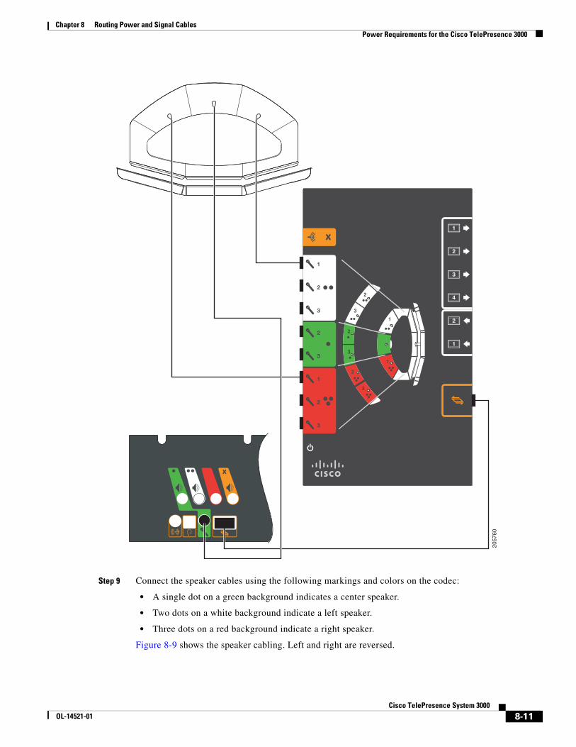
Step 9 Connect the speaker cables using the following markings and colors on the codec:
• A single dot on a green background indicates a center speaker.
• Two dots on a white background indicate a left speaker.
• Three dots on a red background indicate a right speaker.
Figure 8-9 shows the speaker cabling. Left and right are reversed.
2057
60
8-11Cisco TelePresence System 3000
OL-14521-01

Chapter 8 Routing Power and Signal Cables Power Requirements for the Cisco TelePresence 3000
Figure 8-9 Cabling the Speakers
Tip Before plugging cables into the Codec, label each one. For example, Left Speaker, Center Speaker.
Step 10 Connect the following cables:
• Attach and route the power cables for the lighting assembly by connecting the lights to the auxiliary control unit.
• Connect the DSUB to 8-P MINI DIN cable between the projector and the auxiliary control unit.
• Connect the Ethernet cables between the codec and the auxiliary control unit.
• Connect the power cord for the auxiliary control unit to a wall outlet.
Signal
2011
90
2
8-12Cisco TelePresence System 3000
OL-14521-01

Chapter 8 Routing Power and Signal Cables Power Requirements for the Cisco TelePresence 3000
Figure 8-10 Cabling the Lighting Assembly Power Cables and Auxiliary Control Unit-to-Projector Serial Cable
Tip Before plugging the Light fixture power cables into the auxiliary control unit, label each one. For example, 5’ Left light, 4’ Right light.
Primary Codec
1 2 1 2
10/100 NETWORK PORTSRESETSERIAL PORTS
TelePresence
3DEF
6MNO
9WXYZ
#
2ABC
5JKL
8TUV
0OPER
1
4GHI
7PQRS
CISCO IP PHONE7970
Power
Projector20
4158RJ45 Ethernet
Auxiliary Control UnitAuxiliary Control UnitAuxiliary Control Unit
8-13Cisco TelePresence System 3000
OL-14521-01
Chapter 8 Routing Power and Signal Cables Power Requirements for the Cisco TelePresence 3000
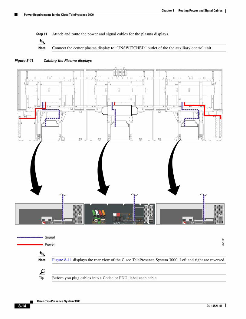
Step 11 Attach and route the power and signal cables for the plasma displays.
Note Connect the center plasma display to “UNSWITCHED” outlet of the the auxiliary control unit.
Figure 8-11 Cabling the Plasma displays
Note Figure 8-11 displays the rear view of the Cisco TelePresence System 3000. Left and right are reversed.
Tip Before you plug cables into a Codec or PDU, label each cable.
Signal
Power 2041
64
8-14Cisco TelePresence System 3000
OL-14521-01

Chapter 8 Routing Power and Signal Cables Power Requirements for the Cisco TelePresence 3000
Step 12 Connect the camera assembly cables.
Figure 8-12 Cabling the Camera assembly
Note The camera cluster can experience radio frequency interference issues if the camera Ethernet and video cables are routed, bundled, or tied together. Cisco recommends that you route the Ethernet and video cables separately and use cable ties to tie them to opposite sides of the frame.
Figure 8-12 displays the rear view of the Cisco TelePresence System 3000. Left and right are reversed.
Tip Before you plug cables into a Codec, label each cable.
RJ45 Power over Ethernet
HDMI connector 2041
65
105
8-15Cisco TelePresence System 3000
OL-14521-01
Chapter 8 Routing Power and Signal Cables Power Requirements for the Cisco TelePresence 3000
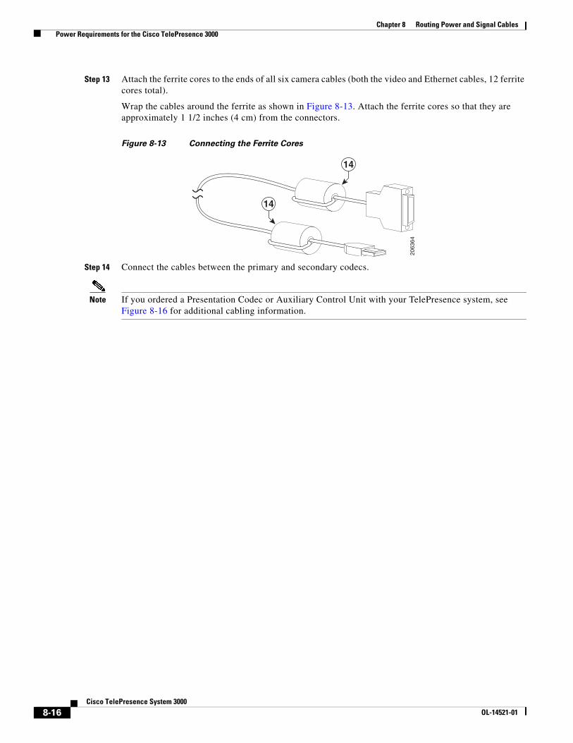
Step 13 Attach the ferrite cores to the ends of all six camera cables (both the video and Ethernet cables, 12 ferrite cores total).
Wrap the cables around the ferrite as shown in Figure 8-13. Attach the ferrite cores so that they are approximately 1 1/2 inches (4 cm) from the connectors.
Figure 8-13 Connecting the Ferrite Cores
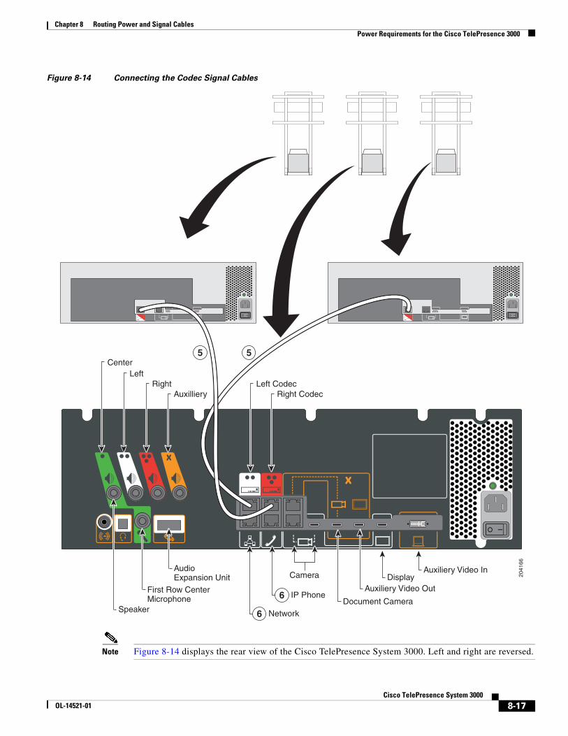
Step 14 Connect the cables between the primary and secondary codecs.
Note If you ordered a Presentation Codec or Auxiliary Control Unit with your TelePresence system, see Figure 8-16 for additional cabling information.
14
14
2063
64
8-16Cisco TelePresence System 3000
OL-14521-01
Chapter 8 Routing Power and Signal Cables Power Requirements for the Cisco TelePresence 3000
Figure 8-14 Connecting the Codec Signal Cables
Note Figure 8-14 displays the rear view of the Cisco TelePresence System 3000. Left and right are reversed.
5 5
6
6
2041
66
Auxiliery Video Out
Camera
IP Phone
Network
LeftRight
Auxilliery
AudioExpansion Unit
Document Camera
Left CodecRight Codec
Center
DisplayAuxiliery Video In
First Row CenterMicrophone
Speaker
8-17Cisco TelePresence System 3000
OL-14521-01

Chapter 8 Routing Power and Signal Cables Power Requirements for the Cisco TelePresence 3000
Cable routing for the auxiliary control unit and projector for a standard CTS 3000 installation is shown in Figure 8-15.
Figure 8-15 Cable Routing for Standard CTS 3000
1 2 1 2
10/100 NETWORK PORTSRESETSERIAL PORTS
Primary Codec
Auxiliary Control UnitProjector
Auxiliary Video Out
Camera
IP Phone
Auxiliarynetworkport
Network
Left Right
Document Camera
Left CodecRight CodecCenter
DisplayAuxiliary Video In
Video InSerial
First RowCenter Microphone
Audio ExpansionUnit
Speaker
Serial 2Serial 1
Ethernet 1Ethernet 2
8-18Cisco TelePresence System 3000
OL-14521-01
Chapter 8 Routing Power and Signal Cables Power Requirements for the Cisco TelePresence 3000
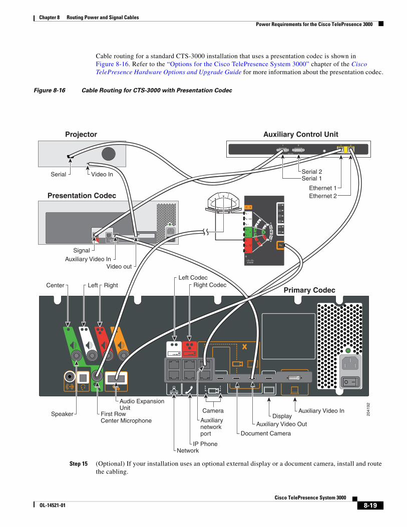
Cable routing for a standard CTS-3000 installation that uses a presentation codec is shown in Figure 8-16. Refer to the “Options for the Cisco TelePresence System 3000” chapter of the Cisco TelePresence Hardware Options and Upgrade Guide for more information about the presentation codec.
Figure 8-16 Cable Routing for CTS-3000 with Presentation Codec
Step 15 (Optional) If your installation uses an optional external display or a document camera, install and route the cabling.
2041
92
1 2 1 2
10/100 NETWORK PORTSRESETSERIAL PORTS
Primary Codec
Auxiliary Control UnitProjector
Presentation Codec
Auxiliary Video Out
Camera
IP Phone
Auxiliarynetworkport
Network
Left Right
Document Camera
Left CodecRight CodecCenter
DisplayAuxiliary Video In
Auxiliary Video InVideo out
Video InSerial
First RowCenter Microphone
Audio ExpansionUnit
Speaker
Serial 2Serial 1
Ethernet 1Ethernet 2
Signal
8-19Cisco TelePresence System 3000
OL-14521-01

Chapter 8 Routing Power and Signal Cables Power Requirements for the Cisco TelePresence 3000
Note Because you need to split the video signal between the projector and any additional video output, you must purchase at least one extra cable to connect optional external display(s). Cables for the external displays and document camera are not included with the standard Cisco TelePresence installation.
Note When you use the audio/video extension unit as a video splitter, connect port 1 of the “Video in” connection from the codec, and port 4 of the “Video out” connection to the projector.
8-20Cisco TelePresence System 3000
OL-14521-01
Chapter 8 Routing Power and Signal Cables Power Requirements for the Cisco TelePresence 3000
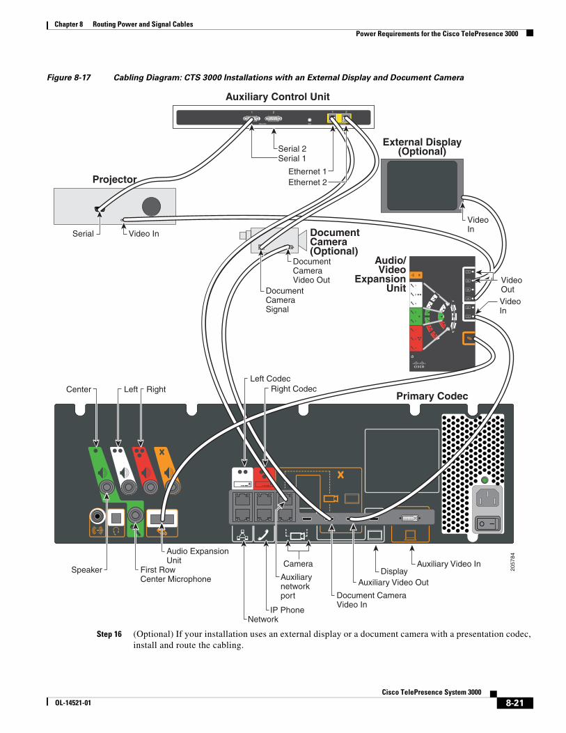
Figure 8-17 Cabling Diagram: CTS 3000 Installations with an External Display and Document Camera
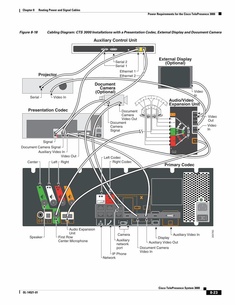
Step 16 (Optional) If your installation uses an external display or a document camera with a presentation codec, install and route the cabling.
2057
84
1 2 1 2
10/100 NETWORK PORTSRESETSERIAL PORTS
DocumentCameraSignal
DocumentCameraVideo Out
Primary Codec
Audio/Video
ExpansionUnit
Projector
External Display(Optional)
DocumentCamera(Optional)
Auxiliary Video Out
Camera
IP Phone
Auxiliarynetworkport
Network
Left Right
First RowCenter Microphone
Document CameraVideo In
Left CodecRight CodecCenter
DisplayAuxiliary Video In
Video In
VideoIn
VideoOutVideoIn
Audio ExpansionUnit
Speaker
Auxiliary Control Unit
Serial 2Serial 1
Ethernet 1Ethernet 2
Serial
8-21Cisco TelePresence System 3000
OL-14521-01
Chapter 8 Routing Power and Signal Cables Power Requirements for the Cisco TelePresence 3000
Refer to the “Options for the Cisco TelePresence System 3000” chapter of the Cisco TelePresence Hardware Options and Upgrade Guide for more information about the presentation codec.
Note Because you need to split the video signal between the projector and any additional video output, you must purchase at least one extra cable to connect optional external display(s). Cables for the external displays and document camera are not included with the standard Cisco TelePresence installation.
Note When you use the audio/video extension unit as a video splitter, connect port 1 of the “Video in” connection from the presentation codec, and port 4 of the “Video out” connection to the projector.
8-22Cisco TelePresence System 3000
OL-14521-01
Chapter 8 Routing Power and Signal Cables Power Requirements for the Cisco TelePresence 3000
Figure 8-18 Cabling Diagram: CTS 3000 Installations with a Presentation Codec, External Display and Document Camera
2057
83
1 2 1 2
10/100 NETWORK PORTSRESETSERIAL PORTS
DocumentCameraSignal
DocumentCameraVideo Out
Primary Codec
Projector
External Display(Optional)
Presentation Codec
Auxiliary Video Out
Camera
IP Phone
Auxiliarynetworkport
Network
Left Right
First RowCenter Microphone
Document CameraVideo In
Left CodecRight CodecCenter
DisplayAuxiliary Video In
Document Camera SignalAuxiliary Video In
Video Out
Video In
Audio ExpansionUnit
Speaker
Auxiliary Control Unit
Serial 2Serial 1
Ethernet 1Ethernet 2
Serial
Signal
Audio/VideoExpansion Unit
DocumentCamera
(Optional) VideoIn
VideoOutVideoIn
8-23Cisco TelePresence System 3000
OL-14521-01

Chapter 8 Routing Power and Signal Cables Power Requirements for the Cisco TelePresence 3000
8-24Cisco TelePresence System 3000
OL-14521-01