Ch07 strengthening-fall2016-sent
12
1 Chapter 7 - 1 Chapter 7: Dislocations & Strengthening Mechanisms Dr. Mir Atiqullah Chapter 7 - 2 Ch7: Do we know these Terms? • Cold Working • Dislocation Density • Grain growth- • Crystal lattice • Re-crystallization • Recovery • Slip • Strain hardening • Solid Solution strengthening • Anisotropy • Resolved Shear Stress Read Thru end of the chapter 7 specially mechanisms of strengthening Study example problems- Practice problems from end of chapter. Chapter 7 - 3 Dislocations & Materials Classes • Covalent Ceramics (Si, diamond): Motion hard. -directional (angular) bonding • Ionic Ceramics (NaCl): Motion hard. -need to avoid ++ and - - neighbors. Which arrow shows best slip direction? + + + + + + + + + + + - - - - - - - - - - • Metals: Disl. motion easier. -non-directional bonding -close-packed directions for slip. electron cloud ion cores + + + + + + + + + + + + + + + + + + + + + + + + Polymers? Chapter 7 - 4 Dislocation Motion Dislocations & plastic deformation • Cubic & hexagonal metals - plastic deformation by plastic shear or slip where one plane of atoms slides over adjacent plane by defect motion (dislocations). • If dislocations don't move, deformation doesn't occur! Adapted from Fig. 7.1, Callister 7e.
-
Upload
savanna-holt -
Category
Engineering
-
view
19 -
download
0
Transcript of Ch07 strengthening-fall2016-sent

1
Chapter 7 - 1
Chapter 7:Dislocations & Strengthening
Mechanisms
Dr. Mir Atiqullah
Chapter 7 - 2
Ch7: Do we know these Terms?
• Cold Working• Dislocation Density• Grain growth-• Crystal lattice• Re-crystallization• Recovery• Slip• Strain hardening• Solid Solution strengthening• Anisotropy• Resolved Shear Stress
Read Thru end of the chapter 7 specially mechanisms of strengthening Study example problems-Practice problems from end of chapter.
Chapter 7 - 3
Dislocations & Materials Classes
• Covalent Ceramics(Si, diamond): Motion hard.-directional (angular) bonding
• Ionic Ceramics (NaCl):Motion hard.-need to avoid ++ and - - neighbors.
Which arrow shows best slip direction?
+ + + +
+++
+ + + +
- - -
----
- - -
• Metals: Disl. motion easier.-non-directional bonding-close-packed directions
for slip.electron cloud ion cores
++
++
++++++++ + + + + +
+++++++
Polymers?Chapter 7 - 4
Dislocation MotionDislocations & plastic deformation• Cubic & hexagonal metals - plastic deformation by
plastic shear or slip where one plane of atoms slides over adjacent plane by defect motion (dislocations).
• If dislocations don't move, deformation doesn't occur!
Adapted from Fig. 7.1, Callister 7e.

2
Chapter 7 -
You tube for you..dislocation• https://www.youtube.com/watch?v=quGSf
mt4V6Y• https://www.google.com/search?q=video+
dislocation+motion&sourceid=ie7&rls=com.microsoft:en-US:IE-Address&ie=&oe=&gws_rd=ssl
5 Chapter 7 - 6
Dislocation Motion-Edge , screw• Dislocation moves along slip plane in slip direction –
WHY?• perpendicular to dislocation line• Slip direction same direction as Burgers vector
Edge dislocation
Screw dislocation
Adapted from Fig. 7.2, Callister 7e.
Chapter 7 - 7
Dislocation Characteristics –local stress, annihilation, repulsion,..
Stress due to an edge dislocation strain fields
Interaction between dislocations-Dislocation annihilation.
Plastic Deformation- causes dramatic increase in dislocation-upto 1010/mm2 Source: existing dislocations, grain boundary, internal defects, surface irregularities etc.
Chapter 7 - 8
Slip System (in planes along some directions)– Slip plane - plane allowing easiest slippage
• 1-Wide interplanar spacings – 2-highest planar densities
– Slip direction - direction of movement - Highest linear densities
– FCC Slip occurs on {111} planes (close-packed) in <110> directions (close-packed)
=> total of 12 slip systems in FCC– in BCC & HCP other slip systems occur
Deformation Mechanisms
Adapted from Fig. 7.6, Callister 7e.
3
Chapter 7 - 9
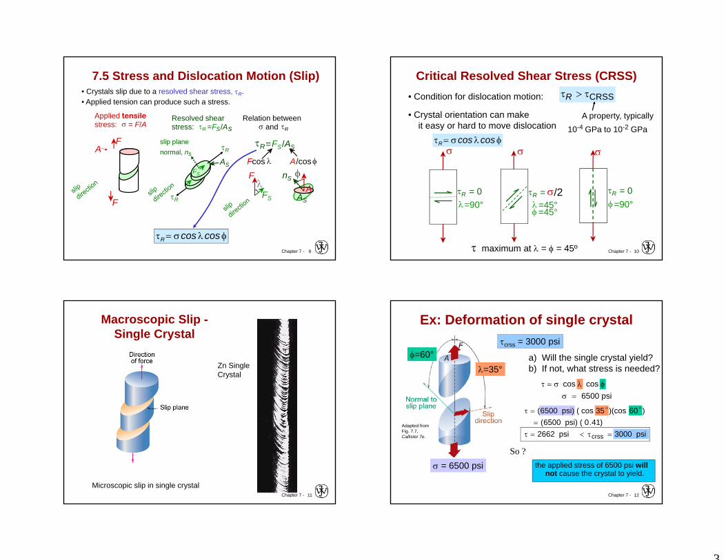
7.5 Stress and Dislocation Motion (Slip)• Crystals slip due to a resolved shear stress, R. • Applied tension can produce such a stress.
slip planenormal, ns
Resolved shear stress: R =Fs/As
AS
R
R
FS
Relation between and R
R=FS/AS
Fcos A/cos
F
FS
nS
AS
A
Applied tensile stress: = F/A
FA
F
coscosR
Chapter 7 - 10
• Condition for dislocation motion: CRSS R
• Crystal orientation can makeit easy or hard to move dislocation 10-4 GPa to 10-2 GPa
A property, typically
coscosR
Critical Resolved Shear Stress (CRSS)
maximum at = = 45º
R = 0=90°
R = /2=45°=45°
R = 0=90°
Chapter 7 - 11
Macroscopic Slip -Single Crystal
Microscopic slip in single crystal
Zn Single Crystal
Chapter 7 - 12
Ex: Deformation of single crystal
the applied stress of 6500 psi will not cause the crystal to yield.
cos cos 6500 psi
=35°=60°
(6500 psi) ( cos 35 )(cos 60 ) (6500 psi) ( 0.41) 2662 psi crss 3000 psi
crss = 3000 psi
a) Will the single crystal yield? b) If not, what stress is needed?
= 6500 psi
Adapted from Fig. 7.7, Callister 7e.
So ?

4
Chapter 7 - 13
Ex: Deformation of single crystal
psi 732541.0
psi 3000coscos
crss
y
Then What stress is necessary to yield (i.e., what is the yield stress, y)?
)41.0(cos cos psi 3000crss yy
psi 7325 y
So for deformation to occur the applied stress must be greater than or equal to the yield stress
Chapter 7 - 14
• Stronger - grain boundariespin deformations
• Slip planes & directions(, ) change from onecrystal to another.
• R will vary from onecrystal to another.
• The crystal with thelargest R yields first.( yield Jogging?)
• Other (less favorablyoriented) crystalsyield later.
Adapted from Fig. 7.10, Callister 7e.(Fig. 7.10 is courtesy of C. Brady, National Bureau of Standards [now the National Institute of Standards and Technology, Gaithersburg, MD].)
Slip Motion in PolycrystalsThe picture can't be displayed.
300 m
Chapter 7 - 15
• Can be induced by rolling a polycrystalline metal - before rolling
235 m- isotropic
since grains areapprox. spherical& randomlyoriented.
- after rolling
- anisotropicsince rolling affects grainorientation and shape.
rolling direction
Adapted from Fig. 7.11, Callister 7e. (Fig. 7.11 is from W.G. Moffatt, G.W. Pearsall, and J. Wulff, The Structure and Properties of Materials, Vol. I, Structure, p. 140, John Wiley and Sons, New York, 1964.)
Anisotropy
Chapter 7 - 16
Technical Term English1. Reduce Grain Size (grain refinement)2. Solid Solution (alloying) (atomic level)3. Precipitation hardening (grain level)4. Cold working – (work hardening)
4 Strategies for Strengthening:

5
Chapter 7 - 17
Strategies for Strengthening:1: Reduce Grain Size
• Grain boundaries arebarriers to slip.
• Barrier "strength"increases withIncreasing angle of misorientation.
• Smaller grain size:more barriers to slip.
• Hall-Petch Equation: (p-189) 21 /yoyield dk
Adapted from Fig. 7.14, Callister 7e.(Fig. 7.14 is from A Textbook of Materials Technology, by Van Vlack, Pearson Education, Inc., Upper Saddle River, NJ.)
St. line on a semi-log plot Fig 7.15 p-189Chapter 7 - 18
Example Problem: Strengthening by Reducing Grain Size
7.22** Given grain Diam. d1= 5E-2 mm, y1=135 Mpa
and at grain Diam. d2= 8E-3 mm y2=260 Mpa
To achieve y= 205 Mpa what should be grain size; d=?
Solution Hints:
1. First determine the co-efficients of Hall-Petch Eqtn.
How: 2 unknowns, use two sets of given data (2 equations).
1. o= ? Ky = ?
2. Then use these and y= 205 Mpa to calc. d = ?
yield o k yd1/2
Can we custom strengthen metals by controlling grain size.
Chapter 7 - 19
• Impurity atoms distort the lattice & generate stress.• Stress can produce a barrier to dislocation motion.
Strategies for Strengthening: 2: Solid Solutions
• Smaller substitutionalimpurity
Impurity generates local stress at Aand B that opposes dislocation motion to the right.
A
B
• Larger substitutionalimpurity
Impurity generates local stress at Cand D that opposes dislocation motion to the right.
C
D
Chapter 7 - 20
Stress Concentration at Dislocations
Adapted from Fig. 7.4, Callister 7e.

6
Chapter 7 - 21
Strengthening by Alloying-how?• small impurities tend to concentrate at dislocations• reduce mobility of dislocation increase strength
Adapted from Fig. 7.17, Callister 7e.
Chapter 7 - 22
Strengthening by alloying• large impurities concentrate at dislocations on low
density side
Adapted from Fig. 7.18, Callister 7e.
Chapter 7 - 23
Ex: Solid SolutionStrengthening in Copper – experimental
• Tensile strength & yield strength increase with wt% Ni.
• Empirical relation:
• Alloying increases y and TS.
21 /y C~
Adapted from Fig. 7.16 (a) and (b), Callister 7e.
Tens
ile s
treng
th (M
Pa)
wt.% Ni, (Concentration C)
200
300
400
0 10 20 30 40 50 Yiel
d st
reng
th (M
Pa)
wt.%Ni, (Concentration C)
60
120
180
0 10 20 30 40 50
Chapter 7 - 24
• Hard precipitates are difficult to shear.Ex: Ceramics in metals (SiC in Iron or Aluminum).
• Result:S
~y1
Strategies for Strengthening: 3: Precipitation Strengthening
Large shear stress needed to move dislocation toward precipitate and shear it.
Dislocation “advances” but
precipitates act as “pinning” sites with S.spacing
Side View
precipitate
Top View
Slipped part of slip plane
Unslipped part of slip plane
Sspacing
From superstuarted solid solution (solution heat treatment) by quenching and then by precipitation (natural aging at room temperature or artificial aging at an elevated temperature). E.g Al-Cu, Cu-Be, Cu-Sn, Mg-Al.

7
Chapter 7 - 25
• Internal wing structure on Boeing 767
• Aluminum is strengthened with precipitates formedby alloying.
Adapted from Fig. 11.26, Callister 7e.(Fig. 11.26 is courtesy of G.H. Narayanan and A.G. Miller, Boeing Commercial Airplane Company.)
1.5m
Application:Precipitation Strengthening
Adapted from chapter-opening photograph, Chapter 11, Callister 5e. (courtesy of G.H. Narayanan and A.G. Miller, Boeing Commercial Airplane Company.)
Chapter 7 - 26
Strategies for Strengthening: 4: Cold Work (%CW)
• Room temperature deformation.• Common forming operations change the cross
sectional area:
Adapted from Fig. 11.8, Callister 7e.
-Forging
Ao Ad
force
dieblank
force-Drawing
tensile force
AoAddie
die
-Extrusion
ram billet
container
containerforce die holder
die
Ao
Adextrusion
100 x %o
doA
AACW
-Rolling
rollAo
Adroll
Chapter 7 - 27
• Ti alloy after cold working:
• Dislocations entanglewith one anotherduring cold work.
• Dislocation motionbecomes more difficult.
Adapted from Fig. 4.6, Callister 7e.(Fig. 4.6 is courtesy of M.R. Plichta, Michigan Technological University.)
Dislocations During Cold Work
0.9 m
Chapter 7 - 28
Result of Cold Work
Dislocation density =
– Carefully grown single crystal ca. 103 mm-2
– Deforming sample increases density 109-1010 mm-2
– Heat treatment reduces density 105-106 mm-2
• Yield stress increasesas d increases:
total dislocation lengthunit volume
large hardeningsmall hardening
y0y1

8
Chapter 7 - 29
Effects of Stress at Dislocations
Adapted from Fig. 7.5, Callister 7e.
Chapter 7 - 30
Impact of Cold Work
Adapted from Fig. 7.20, Low carbon steel
• Yield strength (y) increases.• Tensile strength (TS) increases.• Ductility (%EL or %AR) decreases.
As cold work is increased
Chapter 7 - 31
• Expl7.2: What is the tensile strength &ductility after cold working?
Adapted from Fig. 7.19, Callister 7e. (Fig. 7.19 is adapted from Metals Handbook)
%6.35100 x % 2
22
o
dor
rrCW
Cold Work Analysis
% Cold Work
100
300
500
700
Cu
200 40 60
yield strength (MPa)
y = 300MPa
300MPa
% Cold Work
tensile strength (MPa)
200Cu
0
400
600
800
20 40 60
ductility (%EL)
% Cold Work
20
40
60
20 40 6000
Cu
Do =15.2mm
Cold Work
Dd =12.2mm
Copper
340MPa
TS = 340MPa
7%
%EL = 7%
Chapter 7 - 32
An Example Problem7.28** Two previously undeformed cylindrical specimens of an alloy are to be strainhardened by reducing their cross-sectional areas (maintaining circular shape).Specimen 1: initial and final radii are 15 mm and 12 mm.Specimen 2: initial radius is 11 mm, and must have the same deformed hardness asthe first one.Calc. Final radius of the specimen 2.
In order for these two cylindrical specimens to have the same deformed hardness,they must be deformed to the same percent cold work. For the first specimen
%CW =Ao Ad
Aox 100 =
ro2 rd
2
ro2 x 100
= (15 mm)2 (12 mm)2
(15 mm)2x 100 = 36%CW
rd = ro 1 %CW100
= (11 mm) 1 36%CW
100= 8.80 mm
For the second specimen, the deformed radius is computed using the same% CWequation and solving for rd as

9
Chapter 7 - 33
• Results forpolycrystalline iron:
• y and TS decrease with increasing test temperature.• %EL increases with increasing test temperature.• Why? Vacancies
help dislocationsmove past obstacles.
Adapted from Fig. 6.14, Callister 7e.
- Behavior vs. Temperature
2. vacancies replace atoms on the disl. half plane
3. disl. glides past obstacle
-200C
-100C
25C
800
600
400
200
0
Strain
Stre
ss (M
Pa)
0 0.1 0.2 0.3 0.4 0.5
1. disl. trapped by obstacle
obstacle
Chapter 7 - 34
TR
Adapted from Fig. 7.22, Callister 7e.
º
º
TR = recrystallization temperature
What are the 3 Annealing stages?1.2.3.
Chapter 7 - 35
Annihilation reduces dislocation density.
Recovery
• Scenario 1Results from diffusion
• Scenario 2
4. opposite dislocations meet and annihilate
Dislocations annihilate and form a perfect atomic plane.
extra half-plane of atoms
extra half-plane of atoms
atoms diffuse to regions of tension
2. grey atoms leave by vacancy diffusion allowing disl. to “climb”
R
1. dislocation blocked; can’t move to the right
Obstacle dislocation
3. “Climbed” disl. can now move on new slip plane
Chapter 7 - 36
• New grains are formed that:-- have a small dislocation density-- are small-- consume cold-worked grains.
Adapted from Fig. 7.21 (a),(b), Callister 7e.(Fig. 7.21 (a),(b) are courtesy of J.E. Burke, General Electric Company.)
33% coldworkedbrass
New crystalsnucleate after3 sec. at 580C.
0.6 mm 0.6 mm
Recrystallization

10
Chapter 7 - 37
• All cold-worked grains are consumed.
Adapted from Fig. 7.21 (c),(d), Callister 7e.(Fig. 7.21 (c),(d) are courtesy of J.E. Burke, General Electric Company.)
After 4seconds
After 8seconds
0.6 mm0.6 mm
Further Recrystallization
Chapter 7 - 38
• At longer times, larger grains consume smaller ones. • Why? Grain boundary area (and therefore energy)
is reduced.
After 8 s,580ºC
After 15 min,580ºC
0.6 mm 0.6 mmAdapted from Fig. 7.21 (d),(e), Callister 7e.(Fig. 7.21 (d),(e) are courtesy of J.E. Burke, General Electric Company.)
Grain Growth
• Empirical Relation:
Ktdd no
n elapsed time
coefficient dependenton material and T.
grain diam.at time t.
exponent typ. ~ 2
Ostwald Ripening
Chapter 7 - 39
Recrystallization Temperature, TR
TR = recrystallization temperature = point of highest rate of property change-depends on phase diagram of the alloy. Generally:1. TR 0.3-0.6 Tm (K) - Tm melting temp.2. Due to diffusion annealing time (t) TR = f(t)
shorter annealing time => need higher TR
3. Higher %CW => lower TR – strain hardening4. Pure metals lower TR due to dislocation
movements• Easier to move in pure metals. So lower TR
Chapter 7 - 40
7.D6 CW CalculationsProblem: A cylindrical rod of brass originally 0.40 in (10.2 mm) in diameter is to be cold worked by drawing. The circular cross section will be maintained during deformation. A cold-worked tensile strength in excess of 55,000 psi (380 MPa) and a ductility of at least 15 %EL are desired. Furthermore, the final diameter must be 0.30 in (7.6 mm).
Q: How can this be done?

11
Chapter 7 - 41
CW Calc. Solution
If we directly draw to the final diameter what happens?
%843100 x 4003001100 x
441
100 1100 x %
2
2
2
...
DD
xAA
AAACW
o
f
o
f
o
fo
Do = 0.40 in
BrassCold Work
Df = 0.30 in
Chapter 7 - 42
CW Calc. Solution: Cont.
• For %CW = 43.8% Adapted from Fig. 7.19, Callister 7e.
540420
– y = 420 MPa– TS = 540 MPa > 380 MPa
6
– %EL = 6 < 15• This doesn’t satisfy criteria…… what can we do?
Chapter 7 - 43
Coldwork Calc Solution: Cont.
Adapted from Fig. 7.19, Callister 7e.
380
12
15
27
For %EL > 15For TS > 380 MPa > 12 %CW
< 27 %CW
our working range is limited to %CW = 12-27
Chapter 7 - 44
CW Calc. Soln: RecrystallizationCold draw-anneal-cold draw again• For objective we need a cold work of %CW 12-27
– Let’s try %CW = 20• Diameter after first cold draw (before 2nd cold draw)?
– must be calculated as follows:
100%1 100 1% 2
02
22
202
22 CW
DDx
DDCW ff
50
02
2
100%1
.f CW
DD
50
202
100%1
.f
CWDD
m 3350100201300
50
021 ..DD.
f
Intermediate diameter =
12
Chapter 7 - 45
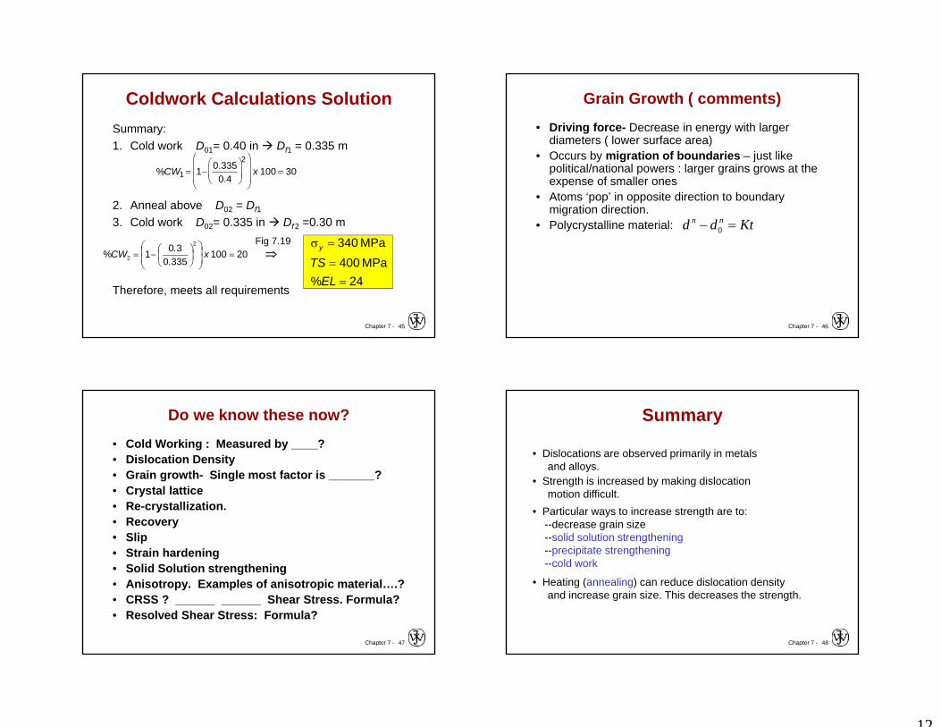
Coldwork Calculations SolutionSummary:1. Cold work D01= 0.40 in Df1 = 0.335 m
2. Anneal above D02 = Df1
3. Cold work D02= 0.335 in Df2 =0.30 m
Therefore, meets all requirements
20100 3350
301%2
2
x
..CW
24%MPa 400MPa 340
ELTS
y
%CW1 1 0.3350.4
2
x 100 30
Fig 7.19
Chapter 7 - 46
Grain Growth ( comments)
• Driving force- Decrease in energy with larger diameters ( lower surface area)
• Occurs by migration of boundaries – just like political/national powers : larger grains grows at the expense of smaller ones
• Atoms ‘pop’ in opposite direction to boundary migration direction.
• Polycrystalline material: Ktdd nn 0
Chapter 7 - 47
Do we know these now?
• Cold Working : Measured by ____?• Dislocation Density • Grain growth- Single most factor is _______?• Crystal lattice• Re-crystallization. • Recovery• Slip• Strain hardening • Solid Solution strengthening• Anisotropy. Examples of anisotropic material….?• CRSS ? ______ ______ Shear Stress. Formula?• Resolved Shear Stress: Formula?
Chapter 7 - 48
• Dislocations are observed primarily in metalsand alloys.
• Strength is increased by making dislocationmotion difficult.
• Particular ways to increase strength are to:--decrease grain size--solid solution strengthening--precipitate strengthening--cold work
• Heating (annealing) can reduce dislocation densityand increase grain size. This decreases the strength.
Summary