Ch. 5 Digital Design with SM Chartcslee/dsd/dsd_vhdl_ch5.pdf · · 2011-06-20Ch. 5 Digital Design...
23
1 Ch. 5 Digital Design with SM Chart ◎ Flowchart for Hardware Design - alternative to state diagram - easier to understand - condition for state graphs are satisfied automatically - direct hardware realization ◎ Examples -multiplier -dice game controller Components of State Machine (Flow) Charts • SM Chart, or ASM(Algorithmic State Machine) Chart • 3 components – 1) State Box 2) Decision Box 3) Conditional Output Box • State box – State_name/output list, output list is optional – Optional state code • Condition: True, False branches • Conditional output box
-
Upload
truongngoc -
Category
Documents
-
view
222 -
download
4
Transcript of Ch. 5 Digital Design with SM Chartcslee/dsd/dsd_vhdl_ch5.pdf · · 2011-06-20Ch. 5 Digital Design...

1
Ch. 5 Digital Design with SM Chart◎ Flowchart for Hardware Design
- alternative to state diagram- easier to understand- condition for state graphs are satisfied automatically- direct hardware realization
◎ Examples-multiplier-dice game controller
Components of State Machine (Flow) Charts
• SM Chart, or ASM(Algorithmic State Machine) Chart• 3 components
– 1) State Box 2) Decision Box 3) Conditional Output Box
• State box– State_name/output list, output list is optional– Optional state code
• Condition: True, False branches• Conditional output box

2
SM Block• Contains only 1 state box +decision +cond. output
– description of one state
– All tests take place in one clock
• 1 Entrance path and one or more exit path
in path 3 z3=z4=0
link path
entrance pathà exit path(s)
Equivalent SM blocks
• (b) is more complex
Next state

3
Equivalent SM Chart for a Combinational Networks
(a) (b)
Z1=1 if (A=1) or (A=0,B=1, and C=1)
i.e. Z1=A+A’BC =A+BC
Rules of SM block
1. For every valid combination of input variables, there must be exactly one exit path defined.
2. Internal feedback is not allowed in SM block
4
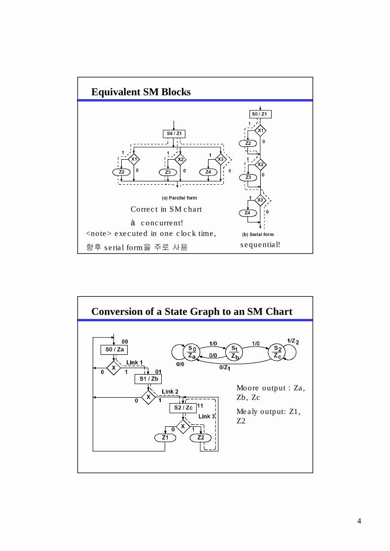
Equivalent SM Blocks
Correct in SM chart
à concurrent!
sequential!
<note> executed in one clock time,
향후 serial form을 주로 사용
Conversion of a State Graph to an SM Chart
Moore output : Za, Zb, Zc
Mealy output: Z1, Z2

5
Timing Chart
5.2 Derivation of SM Charts
• draw block diagram
• define input and output signals
• construct SM chart

6
SM chart for Binary Multiplier
K: completion signal
VHDL for SM Chart of Figure 5-9entity Mult is
port(CLK,St,K,M: in bit;Load,Sh,Ad,Done: out bit);
end mult;architecture SMbehave of Mult is
signal State, Nextstate: integer range 0 to 3;begin
process(St, K, M, State) -- start if state or inputs change
beginLoad <= '0'; Sh <= '0'; Ad <= '0';case State is
when 0 => if St = '1' then -- St (state 0)Load <= '1'; Nextstate <= 1;else Nextstate <= 0; -- St'end if;
when 1 => if M = '1' then -- M (state 1)Ad <= '1'; Nextstate <= 2;else -- M'Sh <= '1'; if K = '1' then Nextstate <= 3;
-- Kelse Nextstate <= 1; -- K'end if;
end if;

7
when 2 => Sh <= '1'; -- (state 2)if K = '1' then Nextstate <= 3; -- Kelse Nextstate <= 1; -- K'end if;
when 3 => Done <= '1'; -- (state 3)Nextstate <= 0;
end case;end process;process(CLK)begin
if CLK = '1' thenState <= Nextstate; -- update state on rising edge
end if;end process;end SMbehave;
Dice Game

8
Flow Chart for Dice Game
SM Chart for Dice Game

9
State Graph for Dice Game Controller
Behavioral Model for Dice Gameentity DiceGame is
port (Rb, Reset, CLK: in bit;Sum: in integer range 2 to 12;Roll, Win, Lose: out bit);
end DiceGame;library BITLIB;use BITLIB.bit_pack.all;architecture DiceBehave of DiceGame is
signal State, Nextstate: integer range 0 to 5;signal Point: integer range 2 to 12;signal Sp: bit;
beginprocess(Rb, Reset, Sum, State)begin
Sp <= '0'; Roll <= '0'; Win <= '0'; Lose <= '0';case State is
when 0 => if Rb = '1' then Nextstate <= 1; end if;when 1 =>
if Rb = '1' then Roll <= '1';elsif Sum = 7 or Sum = 11 then Nextstate <= 2;elsif Sum = 2 or Sum = 3 or Sum =12 then Nextstate <= 3;else Sp <= '1'; Nextstate <= 4;
end if;

10
계속when 2 => Win <= '1';
if Reset = '1' then Nextstate <= 0; end if;when 3 => Lose <= '1';
if Reset = '1' then Nextstate <= 0; end if;when 4 => if Rb = '1' then Nextstate <= 5; end if;when 5 =>
if Rb = '1' then Roll <= '1';elsif Sum = Point then Nextstate <= 2;elsif Sum = 7 then Nextstate <= 3;else Nextstate <= 4;
end if;end case;
end process;process(CLK)begin
if rising_edge(CLK) thenState <= Nextstate;if Sp = '1' then Point <= Sum; end if;
end if;end process;end DiceBehave;
Dice Game with Test Bench

11
SM Chart for Dice Game Test
Dice Game Test Module
entity GameTest is
port(Rb, Reset: out bit; Sum: out integer range 2 to 12;
CLK: inout bit; Roll, Win, Lose: in bit);
end GameTest;
library BITLIB;
use BITLIB.bit_pack.all;
architecture dicetest of GameTest is
signal Tstate, Tnext: integer range 0 to 3;
signal Trig1: bit;
type arr is array(0 to 11) of integer;
constant Sumarray:arr := (7,11,2,4,7,5,6,7,6,8,9,6);
begin
CLK <= not CLK after 20 ns;

12
계속process(Roll, Win, Lose, Tstate)variable i: natural; -- i is initialized to 0begincase Tstate iswhen 0 => Rb <= '1'; -- wait for RollReset <='0';if i>=12 then Tnext <= 3;elsif Roll = '1' thenSum <= Sumarray(i);i:=i+1;Tnext <= 1;end if;when 1 => Rb <= '0'; Tnext <= 2;when 2 => Tnext <= 0;Trig1 <= not Trig1; -- toggle Trig1if (Win or Lose) = '1' then Reset <= '1'; end if;when 3 => null; -- Stop stateend case;end process;process(CLK)beginif CLK = '1' thenTstate <= Tnext;end if;end process;end dicetest;
Tester for Dice Game
entity tester isend tester;architecture test of tester iscomponent GameTestport(Rb, Reset: out bit;Sum: out integer range 2 to 12; CLK: inout bit; Roll, Win, Lose: in bit);end component;component DiceGameport (Rb, Reset, CLK: in bit; Sum: in integer range 2 to 12 ; Roll, Win,
Lose: out bit);end component;signal rb1, reset1, clk1, roll1, win1, lose1: bit; signal sum1: integer
range 2 to 12;beginDice: Dicegame port map(rb1,reset1,clk1,sum1,roll1,win1,lose1);Dicetest: GameTest port map(rb1,reset1,sum1,clk1,roll1,win1,lose1);end test;

13
Simulation and Command File for Dice Game Tester
list /dicetest/ trig1 -NOTrigger sum1 win1 lose1 /dice/pointrun 2000
PLA Table for Multiplier Control
A+ = A'BM'K + A'BM + AB'K = A'B(M + K) + AB'KB+ = A'B'St + A'BM'(K'+K) + AB'(K'+K) = A'B'St + A'BM' + AB'Sh = A'BM'(K'+K) + AB'(K'+K) = A'BM' + AB'Load = A'B'St Ad = A'B M Done = A B

14
PLA Realization of Dice Game Controller
PLA Table for Dice Game

15
Maps Derived from Table 5-2
Data Flow Model for Dice Game
library BITLIB;
use BITLIB.bit_pack.all;
architecture Dice_Eq of DiceGame is
signal Sp,Eq,D7,D711,D2312: bit:='0'; signal DA,DB,DC,A,B,C :bit:='0';
signal Point: integer range 2 to 12;
begin
process(Clk)
begin
if rising_edge(Clk) then
A <= DA; B <= DB; C <= DC;
if Sp = '1' then Point <= Sum; end if;
end if;
end process;

16
계속Win <= B and not C;Lose <= B and C;Roll <= not B and C and Rb;Sp <= not A and not B and C and not Rb and not D711 and not D2312;D7 <= '1' when Sum = 7 else '0';D711 <= '1' when (Sum = 11) or (Sum = 7) else '0';D2312 <= '1' when (Sum = 2) or (Sum = 3) or (Sum = 12) else '0';Eq <= '1' when Point=Sum else '0';DA <= (not A and not B and C and not Rb and not D711 and not
D2312) or(A and not C) or (A and Rb) or (A and not D7 and not Eq);DB <= ( (not A and not B and C and not Rb) and (D711 or D2312) )or (B and not Reset) or ( (A and C and not Rb) and (Eq or D7) );DC <= (not B and Rb) or (not A and not B and C and not D711 and
D2312) or(B and C and not Reset) or (A and C and D7 and not Eq);end Dice_Eq;
Figure 5-24 Counter for Dice Gameentity Counter isport(Clk, Roll: in bit;Sum: out integer range 2 to 12);end Counter;architecture Count of Counter issignal Cnt1,Cnt2: integer range 1 to 6 := 1;begin
process (Clk)beginif Clk='1' then
if Roll='1' thenif Cnt1=6 then Cnt1 <= 1; else Cnt1 <= Cnt1+1; end if;if Cnt1=6 then
if Cnt2=6 then Cnt2 <= 1; else Cnt2 <= Cnt2+1; end if;end if;
end if;end if;end process;Sum <= Cnt1 + Cnt2;end Count;

17
Complete Dice Gameentity Game is
port (Rb, Reset, Clk: in bit;Win, Lose: out bit);
end Game;architecture Play1 of Game is
component Counterport(Clk, Roll: in bit;Sum: out integer range 2 to 12);
end component;component DiceGame
port (Rb, Reset, CLK: in bit;Sum: in integer range 2 to 12;Roll, Win, Lose: out bit);
end component;signal roll1: bit;signal sum1: integer range 2 to 12;
beginDice: Dicegame port map(Rb,Reset,Clk,sum1,roll1,Win,Lose);Count: Counter port map(Clk,roll1,sum1);
end Play1;
Control Network Using an input Muxto Select the Next State

18
PLA/ ROM Table for Figure 5-27

19
MUX for SM Chart of Fig. 5-27
Counter Network using a Counter for State Register

20
SM chart with Serial State Assignment and Added X-states
SM Chart with Serial State Assignment and Added X-state

21
MUX for SM chart of Figure 5-30
PLA Table for Figure 5-31

22
SM Charts for Serially Linked State Machine
Linked SM Charts for Dice Game

23
Linked SM Charts for Dice Game