
Ch 02 (1)
43
ATM –THE WAN PROTOCOL
-
Upload
shraddhabpatel -
Category
Education
-
view
90 -
download
0
Transcript of Ch 02 (1)

ATM –THE WAN PROTOCOL

Introduction• ATM is a flexible and integrated set of transport
services initially designed to transmit all existing type of traffic such as data and multimedia.
• The inherent ability of ATM service is to provide QOS and Traffic engineering characteristics for each traffic make ATM popular and suitable for WAN.
• ATM works on statistical multiplexing that uses the feathers of both the packet switching and circuit switching.
• In cell-relay based network cell consider as a packet and relay as switching, so ATM follow ATM packet switching technology.
• ATM networks are connection orientated and require a connection setup between the sender and receiver prior to the cell transmission,therfore ATM is circuit switching .
• Circuit switching in ATM enable high-speed transmission of data with low delay and packet switching enable utilization of channel bandwidth.

• ATM has two facets:1) Transportation: ATM is neither fast nor slow than
any other technology.2) Switching: ATM is better than other technology
such as x.25 and frame relay.• ATM use fixed and small sized frame that moves
through switches at high speed .• ATM can combine different virtual circuit in virtual
paths which improve its scalability.

Need of ATM• Network would need to accommodate data application as
well as multimedia application.• Initially only text based network could shared by networks
because physical medium used in network provide very slow transmission rate.
• If physical medium based on fiber optic data could be transmitted at higher rate.
• Consequently multimedia services could be shared over the internet. with broadband integrated service Digital Network B-ISDN it is possible to multiplex and prioritize data, voice and video traffic in single interface protocol.
• ATM was consider as a appropriate protocol for WAN services and it was expected that it would enable Qos on LANs.
• Although ATM was an efficient technology ,it is failed to achieve its goals because it could not eliminate other technologies such as frame relay and IP.

Goals of the developers of the ATM• Providing single and integrated carrier
technology that would transmit data related to computer, multimedia and object control simultaneously with the required Qos support .
• Ensuring that technology is compatible and inter connectible with the existing infrastructure and technology without reducing their effectiveness and damaging their replacement.
• Ensuring that technology is fast and economical so that end user can afford it.

Benefits of using ATM• ATM is based on the connection-oriented cell-switching and
multiplexing principle.1) Small Packet size : all packets are equal size so faster in
switching.2) Small header size: allow efficient use of bandwidth3) Dynamic bandwidth: facilitate transfer of bursty traffic
efficiently and fulfill various need of the application4) Fixed size cells: handle various traffic efficiently and swiftly.5) Qos: provide support for integrated service in a network.6) Link speeds: offer wide range of speed due to variety of
supported interfaces. (T1/E1 –(2Mbps) to OC12-(622 Mbps))7) Common LAN/WAN architecture: acts as both LAN and WAN
network Architecture. ATM can be employed in both WAN and LAN.

Faces of ATM• 1) ATM as a economical and integrated services:
– Provide integrated service for data ,voice and video signals.
– It should be inexpensive so that user can afford it
– ATM offer fast alternative to other networks
• 2 )ATM as an architecture and Technology:
– ATM has been the backbone of various infrastructure serving as principle technology for ISP.
– Qos switching and statistical multiplexing are provided by ATM hardware which needed by various network.
– ATM offer scalable infrastructure in both LAN and WAN.
• 3) ATM as interface and protocol:
– To switch traffic virtually and statistically through virtual circuit technique.
– ATM is based on B-ISDN so can be merged with existing infrastructure. e.g IP over ATM

• 4) ATM as a WAN Transport service:–ATM utilize high-speed SONET technology to
serve as a core backbone technology for WAN.–ATM is most suitable technology for WANs
because of high-speed and inherent Qos characteristics.

Basic Concepts of ATM Networking• ATM utilize various benefits of packet switching and circuit switching with time division
multiplexing.
• Atm convert all the data sent to the network into fixed sized cells.
• Cell are –sent to > multiplexer-schedules cells->single channel queue.
• This multiplexing is done through asynchronous Time division multiplexing.
• Asynchronous because multiplexing is not synchronous.
• Transmission in asynchronous mode it has own advantage over synchronous.
• In TDM (synchronous multiplexing) node send its cell when its turn comes and during that period it has nothing to send than slot of time on output channel is empty and bandwidth is wasted.
• ATM remove this drawback by availing free time slot to those nodes that have large number of cell to send.
• How?
• by identifying overloaded node by looking into header of the cell and allowing that node to send cells when the slot is free.
• Asynchronous nature of the ATM enables it to provide bandwidth to the nodes when required

Basic building block of ATM• ATM is a connection-oriented service in which
connection between two parties accomplished through • 1) Transmission path : is a physical channel ( coaxial
/fiber optic) through which data is transmitted in form of stream of bits.– TP contain various VP.
• 2) Virtual path: Connect two nodes or a switch in ATM network.– VP contains several VC.
• 3) Virtual circuit: carry the ATM cells.• e.g. A numbers of highways might be
connecting two cities together.• Assume highways as TP• From set TP ,each highway as VP.• Lanes on a highway consider as a VC.

4) virtual connection: • A VC as a lane in a highway which carry single line of
vehicles through it• This VC forms VCC-virtual channel connection that
links two user or devices• VP as highway that has many lanes through it. set of
all VCCs form a path connection –VPC• ATM is VC network to transfer data we need to identify
connection through which data would be sent.• So ATM use pair of identifier
1)virtual circuit identifier VCI2) virtual path identifier VPI
Through which we can identify virtual connection.

• 5) ATM network interface:– 1) user to network interface (UNI) : between user
device (router ,computer ,gateway) and a network termination equipment(ATM switch).
– 2) network to network interface(NMI):between two network equipment(ATM switch).
– UNI and NMI further classified ,depending on whether the switch owned by customer or a public company• 1) public : NMI between two ATM switch within
same public network. » public UNI between user device and public
ATM switch.• 2) private: private UNI between user device and
private ATM switch.» private NMI exist between two ATM switches
within same private network

ATM Cell
• Cells are basic units of ATM protocol, where information to be transferred is loaded in the cells.
• These cells are of equal size 53 bytes, out of 53 bytes 5 bytes are reserved for header and reaming 48 bytes carry the user data.
• These small-sized cell have an advantage of effectively transferring voice and video traffic.
• These cells are transmitted using physical medium with complete uniformity and certainty.
• These cells are multiplexed with other cells by using various multiplexing techniques.
5 byte header 48 byte payload

ATM operation• On input port of a switch the cell is received ,which
has its own VPI and VCI values.• Switch maintain internal translation table that are
updated automatically or manually depending on the connection
• The first task of the ATM switch is to convert logical address into physical outgoing switch port address and outgoing logical VPI/VCI address.
• So based on the VPI/VCI values switch has to find the output port to forward the cell.
• Switch must also identify the new values of VPI/VCI on the new link.
• VCI/VPI only have logical significance across a particular link: therefore switch find the fresh values for these on the new link.
• This process is done at every switch through which cell pass.
• End switch of a network are VP and VC switches that use both identifiers VPI/VCI.
• Intermediate switch in network are VP switches that use only VPI .

How ATM works?• ATM is connection-oriented -- an end-to-end
connection must be established and routing tables setup prior to cell transmission
• Once a connection is established, the ATM network will provide end-to-end Quality of Service (QoS) to the end users
• All traffic, whether voice, video, image, or data is divided into 53-byte cells and routed in sequence across the ATM network
• Routing information is carried in the header of each cell
• Routing decisions and switching are performed by hardware in ATM switches
• Cells are reassembled into voice, video, image, or data at the destination.

ATM NetworkH
H
H H H
H
H
H
Voice Video Data Voice Video Data
BISDNServices
BISDNServices
Reassembly
User Applications User Applications
Workstation Workstation
Multiplexing Demultiplexing
H H HH H
Segmentation

BROADBAND AND B-ISDN• Broadband:
"A service or system requiring transmission channel capable of supporting rates greater than the primary rate.“
• Broadband-Integrated Service Digital Network (B-ISDN):A standard for transmitting voice, video and data at the same time over fiber optic telephone linesThe goal of B-ISDN is to accommodate all existing services along with those that will come in the future. The services that BISDN will support include (1)narrowband services, such as voice, voice band
data, facsimile, telemetry, video , electronic mail .(2)wideband services such as T1. (3)broadband services such as video conference,
high speed data, video on demand. BISDN is also to support point-to-point, point-to-multipoint and multipoint-to-multipoint connectivity.

ISO-OSI and ATM Models

B-ISDN Reference Model

• Reference model represent the following planes• 1) User plane:
– Deal with data transfer ,flow control, and error recovery.
– Provide support to user application.– This plane has stack of the layers.
• 2) Control plane:– Deal with the creation and management of
signalling connection.– This plane initiate virtual connections and– enables switched virtual circuit capability in
connection on behalf of the user plane– manage function of ATM such as addressing and
routing.• 3) Management plane:
– Consist of layer management and plane management.
– Layer management Manage functions such as network devices and failure identification
– plane management deals with the function associate with the entire plane.

Physical layer • Transmit ATM cell over a physical medium by
transform ATM cell to a frames that appropriate to physical carrier.
• And also identify cell limit and boundaries in the frame.
1) PMD sublayer• Synchronize the actual clocking of bit
transmission over a physical medium by sending and receiving continuous stream of bits with related timing information.
• Deals with other information such as Timing recovery and type of connector.
2) TC sublayer • locating ATM cell boundaries on every
received cell using HEC.• Map the cell into TDM frame format known as
transmission adaption.• Maintain and operate board range of variable
speed physical interface by cell rate decoupling.• In cell rate decoupling TC sublayer inserts a
dummy frames when cells are not available.

ATM layer
• Deal with the connection oriented information of the network e.g. creating and terminating connection, transferring and monitoring the cell through network.
• ATM remove and add 5 byte header from cell when 53 byte cell is transported to AAL and received from AAL.
• Multiplexing and demultiplexing the cell of different connection are also carried out by ATM layer.
• Also provide service such as switching ,routing and traffic management.
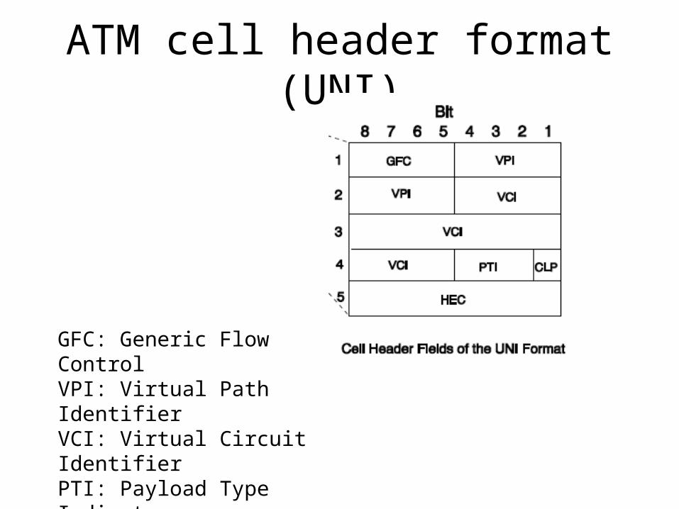
ATM cell header format (UNI)
GFC: Generic Flow ControlVPI: Virtual Path IdentifierVCI: Virtual Circuit IdentifierPTI: Payload Type IndicatorCLP: Cell Loss PriorityHEC: Header Error Control

ATM cell header format (MNI)
VPI: Virtual Path IdentifierVCI: Virtual Circuit IdentifierPTI: Payload Type IndicatorCLP: Cell Loss PriorityHEC: Header Error Control
1) Generic flow control: • provide flow control and shared medium access at
UNI level but currently undefined and thus set to zero• This field is not used at NMI level thus 4 bit allocated
to VPI field that allow defining more paths at the NMI level
2) VPI : • identifies VP of a particular connection and this field is
8 bit long so that total 28 = 256 VPs can be uniquely idetified.In NMI 212=4096
• VPI is first part of the ATM addressing and higher priority than VCI
3) VCI: • identifies VC of a particular connection and this field is
16 bit long so that total 216 = 65536 VCs can be uniquely identified.
• VCI is first part of the ATM addressing and lower priority.
4) Payload Type:1st bit type of the payload cell is carrying ,2nd bit congestion identifier,3rd bit whether this cell is last cell or not

5) Cell Loss priority:• indicate priority of ATM cell• A cell with CLP bit as 0 has high priority and not discarded
by ATM switch.• A cell with CLP bit as 1 has low priority and discarded
when network is congested to provide Qos to high priority cells.
6) HEC:• contain cyclic redundancy of length 8 bit for cell header.• not only detect error but also corrects a large class of
multiple bit errors.• this error checking offer security.
UNI and NMI differ only in the GEC field and size of the VPI field.

Qos parameter• Parameter belonging to a non-negotiate group• 1) Cell Error Ratio (CER): refer to the cell with bit
errors or payload errors to the total number of cells delivered in given transmission.
• Depends on the physical medium used in a network.• 2) Cell Misinsertion Ratio( CMR):cells that are
received by destination node but not sent by the source node to total number of the cell delivered in given transmission.
• Misdelivered cells due to header errors that are not detected at the time of transmission
• 3)Severely Errored Cell Block Ratio (SECBR): severely errored block transmitted to total number of cell block delivered.

• Parameter belonging to negotiable group4) Cell Loss Ratio(CLR) :ratio of number of cell lost to number of cell delivered.• Its value is either network specific or left unspecified.• And extent to which its value can be negotiated depends
on the buffer allocation strategies.5) Cell Transfer Delay(CTD):refer to the time elapsed
between a cell exiting a source UNI and the same cell entering a destination UNI for particular connection.
• This delay in cell transfer timing includes queuing delay, processing delay, propagation delay through multiplexer and switches.
6) Cell Delay Variation (CDV): refer to the variation in delay observed by the cells during transmission.
• CDV= (CTD) max- (CTD)min• Maximum and minimum CTD observed by the cells in a
given transmission.

Traffic parameters• Traffic parameters are the variables that define the capacity of
the network and also the traffic congestion faced by the network.
• 1) Peak Cell Rate (PCR): specifies the maximum rate of data transmission that a source cannot exceed.
• PCR determine how often cells can be transmitted in an ATM network.
• 2)Sustainable Cell Rate (SCR): specifies the maximum average cell transmission rate in a network measured over a long period of time.
• 3) Maximum Burst Size(MBS): refers to the maximum number of the cells that can be sent consecutively at PCR by source end.
• 4)Minimum Cell Rate(MCR) : refers to the minimum average rate of the data transmission that the source generally sends.
• 5)Cell Delay Variation Tolerance (CDVT): specifies the tolerances level of the cell delay variation during a transmission.

ATM Protocol Service Categories• 1) Constant Bit Rate(CBR):
– Required fixed amount of bandwidth as described by PCR.
– Application belonging to this service category can not tolerate any variation in delay.
– Such application deal with voice ,video traffic and circuit emulation and need constant cell transfer rate.
• 2) Real time variable bit rate (rt-VBR) : – Supports traffic whose information rate fluctuates
with time– Application belonging to this service category are
delay sensitive and required synchronization between clocks of sender and receiver.
– Such application deal with bursty traffic• 3) Non Real Time VBR (nrt-VBR) :
– Required constant average data rate as in rt-VBR

– It does not required synchronization between clocks of sender and receiver.
– Application belonging to this service category not affected by cell delay and CDV.
• 4) Available Bit Rate (ABR) : – Supports application that can vary the rate of generated
traffic according to the congestion in the network.– Such application uses available bandwidth dynamically.– And application required congestion control
mechanism to adjust the rate of data transmission in the network.
• 5) Unspecified Bit Rate (UBR) :– Supports application in which there are no Qos
requirement and which do not specifies any data transmission rate.
– It is a best efforts services and does not guarantee any specified information rate or Qos characteristics.

Traffic Contract• Traffic management refer to the set of the control
functions which together provide proper level of the service to connection.
• To ensure required Qos to every connection, network must provide suitable set of the resources to all connections.
• Network should ensure that new VCs are allocated to links that have enough available bandwidth.
• Qos guarantee are applicable to the connection only if user traffic follows a connection contract.
• A connection is considered to be complaint with is contract only if fraction of non conforming cells does not exceed a specified value of the network operators.
• Various traffic control mechanism are used to force the traffic contract on every user.

ATM Adaption Layer
AAL
ATM
User information
User information
AAL
ATM
PHYPHY
ATM
PHY
ATM
PHY
End system End systemNetwork

• AAL accept data from the higher layer protocols and convert them into fixed size ATM cell, which are then available to the lower layers, ATM layer.
• At receiving node the process is reversed: received cell are reassembled to form the message and then delivered to the higher layer.
• Function of the AAL is to provide support to the layer above it.
• 1) Segmentation and Reassembly Sublayer (SAR) : – Segment the message received from the higher
layer into cells at the sending node .– Reassemble the received cells from the network to
form the original message at the receiving node.– Function of the SAR sublayer is similar for all types
of AAL.

• 2) Convergence Sublayer (CS) : • Ensure integrity of the data
that is being sent or received in a network
• For all traffic types that required synchronization between end nodes, CS provide synchronization
• It also manage and correct bit errors in the user data.
• CS further subdivided into two part: – 1) Common specific part
Convergence Sublayer (CPCS) : is to deal with packet framing and error detection in AAL
– 2) Service specific part convergence Sublayer(SSCS): is to look into the requirement of the specific classes of AAL.

• The AAL protocol model depends on the AAL service Classes and their attribute
1) Class A: refer to the connection oriented CBR service.• Service for this class is intended for the traffic
for which rigorous timing is required.2) Class B: refer to the connection oriented VBR service.
• Similar to class A, Service for this class is intended for the traffic for which rigorous timing is required.
3) Class C: refer to the connection oriented VBR service.•Service for this class is intended for the traffic
that does not have rigorous timing is required
4) Class D: refer to the connectionless UBR service.• Similar to class C, Service for this class is intended for the traffic that does not have rigorous timing is required
5) Class X: refer to the ABR service, Service for this class is intended for the traffic that does not have rigorous timing is required

AAL 1• AAL 1 protocol supports Class A traffic CBR , which
required transfer of cells at a constant rate.• Typical services that use AAL1 are digital voice and
video, which are sensitive to delay as well as losses.• Transfer of this type of service via ATM resembles
normal leased digital links.• Payload received through higher layer undergoes the
following processing in AAL.• CS received the data stream and segments it into 47
bytes payload.• Pass it to SAR sublayer.• CS does not add any header to it, but SAR adds 1 byte
of header to 47 byte payload received from CS.• This 1 byte header has 4-bit field

• Sequence Number (SN) : – contains convergence sublayer indicator(CSI) in the
first bit followed by 3-bit SN.– SN used for identifying and observing the loss and
misinsertion of SAR payloads.– Sequence Number Protection (SNP): protects the
first field by using check bits that have correction ability for the SAR header.
Header SN SNP 47 Octets Payload
SAR PDU
CSI SeqCount EPCRC
1 3 3 1

AAL 2• AAL 2 protocol was to transmit Class B traffic that generate
information at VBR and has end-to end timing requirement.• Application that use AAL2 can be compressed video, which
generates a stream of bits that varies broadly depending on the level of details and level of motion in scene.
• AAL 2 protocol for Class B traffic was never completed so removed from ATM protocol stack.
• AAL 2 which was proposed to be bandwidth efficient transfer of low bit rate traffic and short frame traffic that has low delay requirement.
• AAL2 incorporate multiplexing to VP/VC hierarchy of ATM to facilitate sharing of single ATM connection by two or more low bit rate users.
• AAL2 facilitates multiplexing of short packets into one cell.

ATM Physical Interfaces• ATM can operate on variety of physical interface.• Properties of standard physical interface.• 1) Data rate: specifies the information of data rate or
bandwidth of physical medium.• 2)Physical Medium: specifies the type of physical
medium used for the communication and the type of the signal it can carry.
• Physical media is divided into two category– 1) Optical media: includes multimode fiber and
single –mode fiber– 2)Electrical media :include coaxial cable,
unshielded twisted pair, foil twisted pair• 3) Framing Type: defines the specification for the
framing ATM cells to physical medium dependent frames.– Framing type includes:

• 1) ATM 25: denote 25.6 Mbps connection over UTP which is generally used for desktop connection
• 2)Transparent Asynchronous Transmitter/Receiver Interface4B/5B: connection over 100 Mbps over multimode fiber.
• 3)Digital signal level 1(DS-1) :denote 1.544 T1 and 2.108 E1 connections
• 4)Digital signal Level -3 (DS-3) : denote 44.736 T1 and 34.368 E1 connections.
• 5)SONET :used for high speed transmission over optical or electrical media.
• Physical interface on ATM switch must supports all the their characteristics –framing data rate and physical medium.
• Physical interface depends on a number of variables including bandwidth requirement and link distance.
• The usage of UTP are as follows:– Desktop Application– Multimode fiber between wiring closets or building– SM fiber across long distance

Choosing Appropriate ATM Public Service
• Variety of services offered by ATM service providers, which includes ATM cell relay services, IP over ATM , Voice over ATM.
• While selecting service provider following few point must be kept in mind.
• Type and Speed Class of access• Qos and service class offered• Network management support• Consumer premises equipment support• Billing options• When organization purchase an ATM connection first it
has to buy physical interface DS-3 or OC-12 depending on the requirement of the organization
• Then it needs a logical ATM port and VPs/VCs for every location.
• Then Qos requirement for that network can be set according to the class of service desired.


![marketing ch#1[04-02-2011]](https://static.fdocuments.net/doc/165x107/577d2eac1a28ab4e1eafb1dc/marketing-ch104-02-2011.jpg)


![Ch 02-foundations of individual[1]](https://static.fdocuments.net/doc/165x107/559c667d1a28ab84488b4588/ch-02-foundations-of-individual1.jpg)


