CFD Topology Optimization of Automotive Components - Ansys · 2019-10-15 · CFD Topology...
12
CFD Topology Optimization of Automotive Components Dr.-Ing. Markus Stephan, Dr.-Ing. Dipl.-Phys. Pascal Häußler, Dipl.-Math. Michael Böhm FE-DESIGN GmbH, Karlsruhe, Germany Synopsis Automatic CFD optimization methods play a more and more important role in modern prod- uct development processes. In many cases they integrate analysis and design issues and therefore, straight through optimization processes are of significant importance. Conventional optimization techniques like CAD parameter-based schemes are often limited due to their often extensive computing and modelling time as well as their intrinsic limited solution space. This disadvantage can be overcome by a new optimality criteria (OC) based topology optimi- zation method for ANSYS FLUENT. The paper starts with a brief introduction into the OC-based topology optimization methodol- ogy. With this approach for channel flow problems, CFD emerges from an analysis tool to a design tool: Topology optimization “generates” design proposals for channels with low pres- sure drop automatically within a given design space. Further design objectives like flow ho- mogenization or favoured flow velocity profiles are also possible. The optimization process is coupled to the FLUENT solver solution process at runtime and therefore very efficient: Only one CFD solver run is necessary for the complete optimization. The potential of the new method is discussed based on first results for TOSCA Fluid for ANSYS FLUENT with the optimization of different Automotive Components like an Inter- cooler intake duct from GM. Using an existing design as given design space, the new optimi- zation technique is used to improve pressure drop performance significantly within one single CFD calculation. The achieved pressure drop reduction for this example is approx. 20% while the total volumetric change of the design is less than 3 %. 1. INTRODUCTION Computational fluid dynamics (CFD) today is widely used in the process of developing and /or improving new products and solutions in almost every industry. Employing CFD tech- niques facilitates a better product design and allows for possible failure identification in an early stage of the product development process. During the feedback of the simulation result into modified product solutions technical expert knowledge and construction experience still play an important role. To circumvent costly manual work and to allow also a fast identification of effective and fea- sible designs, automatic optimization schemes are used more and more. Different optimiza- tion techniques play a growing role in different stages of modern product development proc- esses and integrate analysis and design since “optimization” always implies a design change based on a specific analysis. EASC 2009 4th European Automotive Simulation Conference Munich, Germany 6-7 July 2009 Copyright ANSYS, Inc.
Transcript of CFD Topology Optimization of Automotive Components - Ansys · 2019-10-15 · CFD Topology...
CFD Topology Optimization of Automotive Components Dr.-Ing. Markus Stephan, Dr.-Ing. Dipl.-Phys. Pascal Häußler, Dipl.-Math. Michael Böhm FE-DESIGN GmbH, Karlsruhe, Germany Synopsis Automatic CFD optimization methods play a more and more important role in modern prod-uct development processes. In many cases they integrate analysis and design issues and therefore, straight through optimization processes are of significant importance. Conventional optimization techniques like CAD parameter-based schemes are often limited due to their often extensive computing and modelling time as well as their intrinsic limited solution space. This disadvantage can be overcome by a new optimality criteria (OC) based topology optimi-zation method for ANSYS FLUENT. The paper starts with a brief introduction into the OC-based topology optimization methodol-ogy. With this approach for channel flow problems, CFD emerges from an analysis tool to a design tool: Topology optimization “generates” design proposals for channels with low pres-sure drop automatically within a given design space. Further design objectives like flow ho-mogenization or favoured flow velocity profiles are also possible. The optimization process is coupled to the FLUENT solver solution process at runtime and therefore very efficient: Only one CFD solver run is necessary for the complete optimization. The potential of the new method is discussed based on first results for TOSCA Fluid for ANSYS FLUENT with the optimization of different Automotive Components like an Inter-cooler intake duct from GM. Using an existing design as given design space, the new optimi-zation technique is used to improve pressure drop performance significantly within one single CFD calculation. The achieved pressure drop reduction for this example is approx. 20% while the total volumetric change of the design is less than 3 %. 1. INTRODUCTION Computational fluid dynamics (CFD) today is widely used in the process of developing and /or improving new products and solutions in almost every industry. Employing CFD tech-niques facilitates a better product design and allows for possible failure identification in an early stage of the product development process. During the feedback of the simulation result into modified product solutions technical expert knowledge and construction experience still play an important role. To circumvent costly manual work and to allow also a fast identification of effective and fea-sible designs, automatic optimization schemes are used more and more. Different optimiza-tion techniques play a growing role in different stages of modern product development proc-esses and integrate analysis and design since “optimization” always implies a design change based on a specific analysis.
EASC 20094th European Automotive Simulation Conference
Munich, Germany6-7 July 2009
Copyright ANSYS, Inc.
Parametrized (CAD-) Model Available Design Space (meshed)
exam
ples
of p
ossi
ble
desi
gn v
aria
nts
exam
ples
of p
ossi
ble
desi
gn v
aria
nts
initi
al d
esig
nin
itial
des
ign
Topology OptimizationTopology OptimizationParametric OptimizationParametric Optimization
... ...
Parametrized (CAD-) Model Available Design Space (meshed)
exam
ples
of p
ossi
ble
desi
gn v
aria
nts
exam
ples
of p
ossi
ble
desi
gn v
aria
nts
initi
al d
esig
nin
itial
des
ign
Topology OptimizationTopology OptimizationParametric OptimizationParametric Optimization
... ...
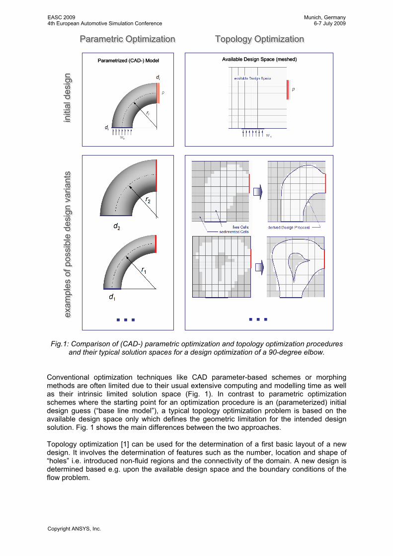
Fig.1: Comparison of (CAD-) parametric optimization and topology optimization procedures
and their typical solution spaces for a design optimization of a 90-degree elbow. Conventional optimization techniques like CAD parameter-based schemes or morphing methods are often limited due to their usual extensive computing and modelling time as well as their intrinsic limited solution space (Fig. 1). In contrast to parametric optimization schemes where the starting point for an optimization procedure is an (parameterized) initial design guess (“base line model”), a typical topology optimization problem is based on the available design space only which defines the geometric limitation for the intended design solution. Fig. 1 shows the main differences between the two approaches. Topology optimization [1] can be used for the determination of a first basic layout of a new design. It involves the determination of features such as the number, location and shape of “holes” i.e. introduced non-fluid regions and the connectivity of the domain. A new design is determined based e.g. upon the available design space and the boundary conditions of the flow problem.
EASC 20094th European Automotive Simulation Conference
Munich, Germany6-7 July 2009
Copyright ANSYS, Inc.
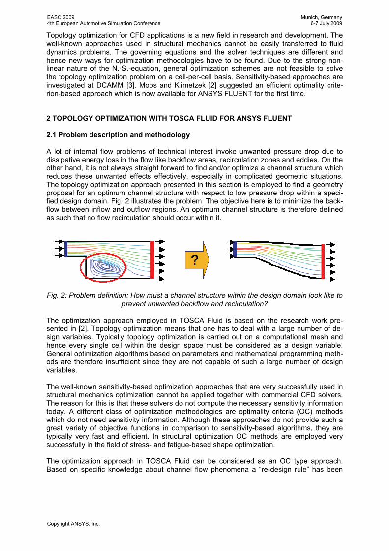
Topology optimization for CFD applications is a new field in research and development. The well-known approaches used in structural mechanics cannot be easily transferred to fluid dynamics problems. The governing equations and the solver techniques are different and hence new ways for optimization methodologies have to be found. Due to the strong non-linear nature of the N.-S.-equation, general optimization schemes are not feasible to solve the topology optimization problem on a cell-per-cell basis. Sensitivity-based approaches are investigated at DCAMM [3]. Moos and Klimetzek [2] suggested an efficient optimality crite-rion-based approach which is now available for ANSYS FLUENT for the first time. 2 TOPOLOGY OPTIMIZATION WITH TOSCA FLUID FOR ANSYS FLUENT 2.1 Problem description and methodology A lot of internal flow problems of technical interest invoke unwanted pressure drop due to dissipative energy loss in the flow like backflow areas, recirculation zones and eddies. On the other hand, it is not always straight forward to find and/or optimize a channel structure which reduces these unwanted effects effectively, especially in complicated geometric situations. The topology optimization approach presented in this section is employed to find a geometry proposal for an optimum channel structure with respect to low pressure drop within a speci-fied design domain. Fig. 2 illustrates the problem. The objective here is to minimize the back-flow between inflow and outflow regions. An optimum channel structure is therefore defined as such that no flow recirculation should occur within it.
Fig. 2: Problem definition: How must a channel structure within the design domain look like to prevent unwanted backflow and recirculation?
The optimization approach employed in TOSCA Fluid is based on the research work pre-sented in [2]. Topology optimization means that one has to deal with a large number of de-sign variables. Typically topology optimization is carried out on a computational mesh and hence every single cell within the design space must be considered as a design variable. General optimization algorithms based on parameters and mathematical programming meth-ods are therefore insufficient since they are not capable of such a large number of design variables. The well-known sensitivity-based optimization approaches that are very successfully used in structural mechanics optimization cannot be applied together with commercial CFD solvers. The reason for this is that these solvers do not compute the necessary sensitivity information today. A different class of optimization methodologies are optimality criteria (OC) methods which do not need sensitivity information. Although these approaches do not provide such a great variety of objective functions in comparison to sensitivity-based algorithms, they are typically very fast and efficient. In structural optimization OC methods are employed very successfully in the field of stress- and fatigue-based shape optimization. The optimization approach in TOSCA Fluid can be considered as an OC type approach. Based on specific knowledge about channel flow phenomena a “re-design rule” has been
EASC 20094th European Automotive Simulation Conference
Munich, Germany6-7 July 2009
Copyright ANSYS, Inc.
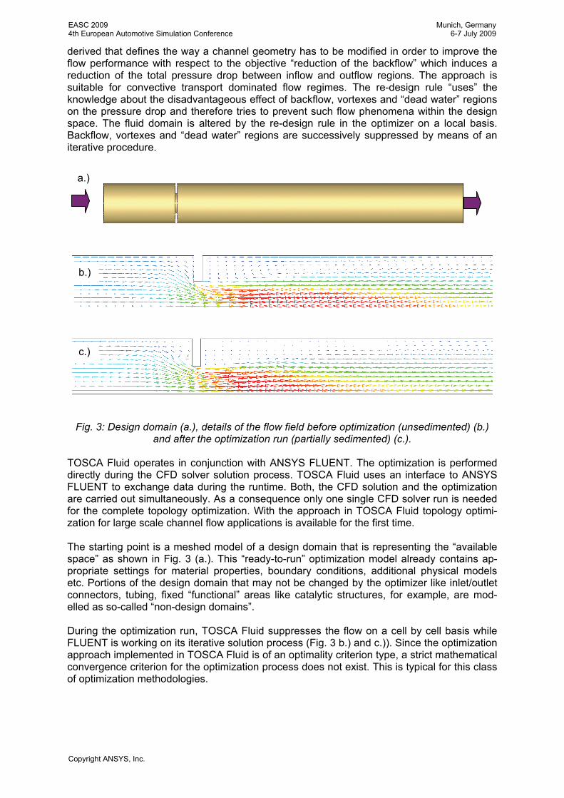
derived that defines the way a channel geometry has to be modified in order to improve the flow performance with respect to the objective “reduction of the backflow” which induces a reduction of the total pressure drop between inflow and outflow regions. The approach is suitable for convective transport dominated flow regimes. The re-design rule “uses” the knowledge about the disadvantageous effect of backflow, vortexes and “dead water” regions on the pressure drop and therefore tries to prevent such flow phenomena within the design space. The fluid domain is altered by the re-design rule in the optimizer on a local basis. Backflow, vortexes and “dead water” regions are successively suppressed by means of an iterative procedure.
Fig. 3: Design domain (a.), details of the flow field before optimization (unsedimented) (b.) and after the optimization run (partially sedimented) (c.).
TOSCA Fluid operates in conjunction with ANSYS FLUENT. The optimization is performed directly during the CFD solver solution process. TOSCA Fluid uses an interface to ANSYS FLUENT to exchange data during the runtime. Both, the CFD solution and the optimization are carried out simultaneously. As a consequence only one single CFD solver run is needed for the complete topology optimization. With the approach in TOSCA Fluid topology optimi-zation for large scale channel flow applications is available for the first time. The starting point is a meshed model of a design domain that is representing the “available space” as shown in Fig. 3 (a.). This “ready-to-run” optimization model already contains ap-propriate settings for material properties, boundary conditions, additional physical models etc. Portions of the design domain that may not be changed by the optimizer like inlet/outlet connectors, tubing, fixed “functional” areas like catalytic structures, for example, are mod-elled as so-called “non-design domains”. During the optimization run, TOSCA Fluid suppresses the flow on a cell by cell basis while FLUENT is working on its iterative solution process (Fig. 3 b.) and c.)). Since the optimization approach implemented in TOSCA Fluid is of an optimality criterion type, a strict mathematical convergence criterion for the optimization process does not exist. This is typical for this class of optimization methodologies.
a.)
b.)
c.)
EASC 20094th European Automotive Simulation Conference
Munich, Germany6-7 July 2009
Copyright ANSYS, Inc.

Convergence of the TOSCA Fluid optimization process can be defined as a state where no significant changes in the flow sedimentation occur anymore. This means that the sedimen-tation distribution introduced by TOSCA Fluid does not change significantly anymore in on-going iterations. A simple measure for this is to monitor the fraction of cells in the design space that are sedimented. If this fraction is almost constant over time within the ongoing iterations, the optimization process can be considered to be converged. Fig. 4 shows a typical development of the fraction of sedimented cells with respect to total number of cells together with the calculated total pressure drop between inlet and outlet against the iteration number.
Fig. 4: Typical development of the fraction of sedimented cells with respect to total number of cells and calculated total pressure drop between inlet and outlet against the iteration number. 2.2 Postprocessing and process integration A TOSCA Fluid optimization ends with a CFD model in which some cells are sedimented and others are not. To extract the geometry proposal for a new channel design several extraction methods are possible. Three extraction methods are currently discussed, namely Velocity, Sedimentation and Particle track filter. The velocity extraction method uses the velocity magnitude of the cells in the model together with a user-defined cut off value to determine, whether or not a cell belongs to the channel structure. The sedimentation extraction method works similar to the velocity extraction method but the sedimentation magnitude of the cells is used instead of the flow velocity. The particle track filer extraction method computes a field of particle tracks based-on the result velocity field in the model. By using the particle runtime of particles on these tracks, the vol-ume made up of the cells penetrated by these tracks and a user-defined cut off value deter-mine a subset of particle tracks. An example result for the particle track filer extraction method and a smoothing result based on this cell set (discussed follows) are shown in Fig 5. The new non-parametric methodology for topology optimization allows the usage of CFD as a „design tool“ in early stages of the product development process. Designs are not only “validated” and investigated with respect to their fluid dynamics properties but are also “de-rived” by means of optimization methodologies.
EASC 20094th European Automotive Simulation Conference
Munich, Germany6-7 July 2009
Copyright ANSYS, Inc.
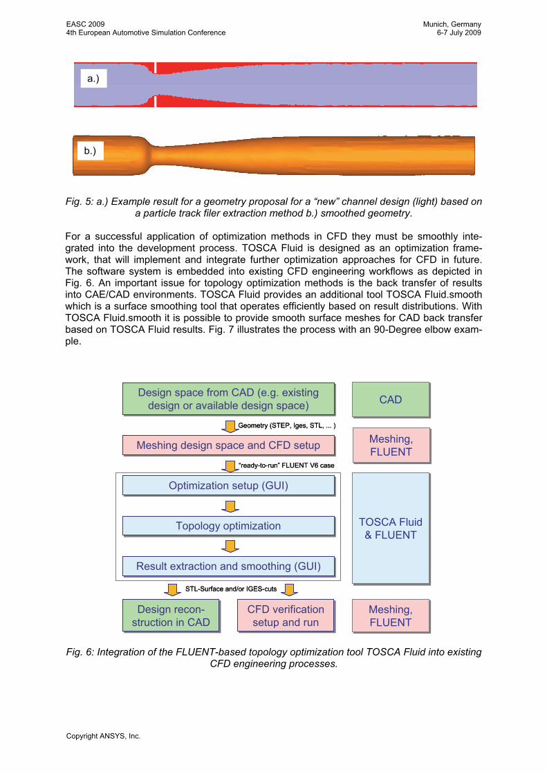
Fig. 5: a.) Example result for a geometry proposal for a “new” channel design (light) based on a particle track filer extraction method b.) smoothed geometry.
For a successful application of optimization methods in CFD they must be smoothly inte-grated into the development process. TOSCA Fluid is designed as an optimization frame-work, that will implement and integrate further optimization approaches for CFD in future. The software system is embedded into existing CFD engineering workflows as depicted in Fig. 6. An important issue for topology optimization methods is the back transfer of results into CAE/CAD environments. TOSCA Fluid provides an additional tool TOSCA Fluid.smooth which is a surface smoothing tool that operates efficiently based on result distributions. With TOSCA Fluid.smooth it is possible to provide smooth surface meshes for CAD back transfer based on TOSCA Fluid results. Fig. 7 illustrates the process with an 90-Degree elbow exam-ple.
Design space from CAD (e.g. existing design or available design space)
Design space from CAD (e.g. existing design or available design space)
Meshing design space and CFD setupMeshing design space and CFD setup
Result extraction and smoothing (GUI)Result extraction and smoothing (GUI)
Design recon-struction in CADDesign recon-
struction in CADCFD verification setup and run
CFD verification setup and run
Topology optimizationTopology optimization
Optimization setup (GUI)Optimization setup (GUI)
CADCAD
TOSCA Fluid & FLUENT
TOSCA Fluid & FLUENT
Meshing, FLUENT Meshing, FLUENT
Meshing, FLUENT Meshing, FLUENT
STL-Surface and/or IGES-cuts
Geometry (STEP, Iges, STL, ... )
“ready-to-run” FLUENT V6 case
Design space from CAD (e.g. existing design or available design space)
Design space from CAD (e.g. existing design or available design space)
Meshing design space and CFD setupMeshing design space and CFD setup
Result extraction and smoothing (GUI)Result extraction and smoothing (GUI)
Design recon-struction in CADDesign recon-
struction in CADCFD verification setup and run
CFD verification setup and run
Topology optimizationTopology optimization
Optimization setup (GUI)Optimization setup (GUI)
CADCAD
TOSCA Fluid & FLUENT
TOSCA Fluid & FLUENT
Meshing, FLUENT Meshing, FLUENT
Meshing, FLUENT Meshing, FLUENT
STL-Surface and/or IGES-cuts
Geometry (STEP, Iges, STL, ... )
“ready-to-run” FLUENT V6 case
Fig. 6: Integration of the FLUENT-based topology optimization tool TOSCA Fluid into existing CFD engineering processes.
a.)
b.)
EASC 20094th European Automotive Simulation Conference
Munich, Germany6-7 July 2009
Copyright ANSYS, Inc.
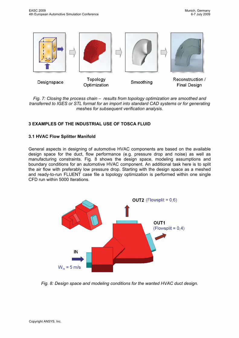
Fig. 7: Closing the process chain – results from topology optimization are smoothed and transferred to IGES or STL format for an import into standard CAD systems or for generating
meshes for subsequent verification analysis.
3 EXAMPLES OF THE INDUSTRIAL USE OF TOSCA FLUID
3.1 HVAC Flow Splitter Manifold General aspects in designing of automotive HVAC components are based on the available design space for the duct, flow performance (e.g. pressure drop and noise) as well as manufacturing constraints. Fig. 8 shows the design space, modeling assumptions and boundary conditions for an automotive HVAC component. An additional task here is to split the air flow with preferably low pressure drop. Starting with the design space as a meshed and ready-to-run FLUENT case file a topology optimization is performed within one single CFD run within 5000 Iterations.
Fig. 8: Design space and modeling conditions for the wanted HVAC duct design.
EASC 20094th European Automotive Simulation Conference
Munich, Germany6-7 July 2009
Copyright ANSYS, Inc.
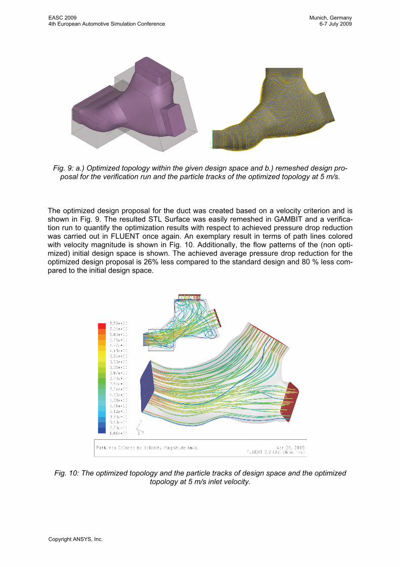
Fig. 9: a.) Optimized topology within the given design space and b.) remeshed design pro-posal for the verification run and the particle tracks of the optimized topology at 5 m/s.
The optimized design proposal for the duct was created based on a velocity criterion and is shown in Fig. 9. The resulted STL Surface was easily remeshed in GAMBIT and a verifica-tion run to quantify the optimization results with respect to achieved pressure drop reduction was carried out in FLUENT once again. An exemplary result in terms of path lines colored with velocity magnitude is shown in Fig. 10. Additionally, the flow patterns of the (non opti-mized) initial design space is shown. The achieved average pressure drop reduction for the optimized design proposal is 26% less compared to the standard design and 80 % less com-pared to the initial design space.
Fig. 10: The optimized topology and the particle tracks of design space and the optimized topology at 5 m/s inlet velocity.
EASC 20094th European Automotive Simulation Conference
Munich, Germany6-7 July 2009
Copyright ANSYS, Inc.
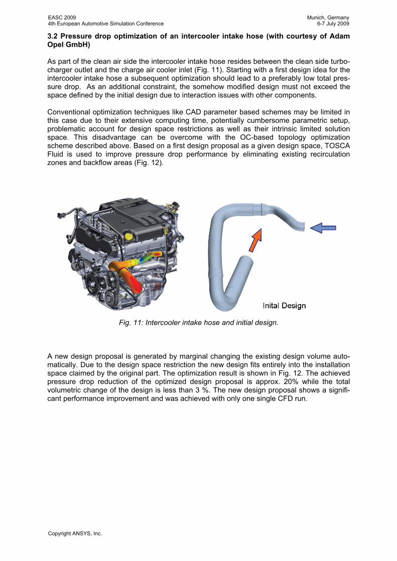
3.2 Pressure drop optimization of an intercooler intake hose (with courtesy of Adam Opel GmbH) As part of the clean air side the intercooler intake hose resides between the clean side turbo-charger outlet and the charge air cooler inlet (Fig. 11). Starting with a first design idea for the intercooler intake hose a subsequent optimization should lead to a preferably low total pres-sure drop. As an additional constraint, the somehow modified design must not exceed the space defined by the initial design due to interaction issues with other components. Conventional optimization techniques like CAD parameter based schemes may be limited in this case due to their extensive computing time, potentially cumbersome parametric setup, problematic account for design space restrictions as well as their intrinsic limited solution space. This disadvantage can be overcome with the OC-based topology optimization scheme described above. Based on a first design proposal as a given design space, TOSCA Fluid is used to improve pressure drop performance by eliminating existing recirculation zones and backflow areas (Fig. 12).
Fig. 11: Intercooler intake hose and initial design.
A new design proposal is generated by marginal changing the existing design volume auto-matically. Due to the design space restriction the new design fits entirely into the installation space claimed by the original part. The optimization result is shown in Fig. 12. The achieved pressure drop reduction of the optimized design proposal is approx. 20% while the total volumetric change of the design is less than 3 %. The new design proposal shows a signifi-cant performance improvement and was achieved with only one single CFD run.
EASC 20094th European Automotive Simulation Conference
Munich, Germany6-7 July 2009
Copyright ANSYS, Inc.
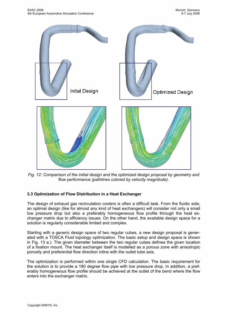
Fig. 12: Comparison of the initial design and the optimized design proposal by geometry and flow performance (pathlines colored by velocity magnitude).
3.3 Optimization of Flow Distribution in a Heat Exchanger The design of exhaust gas recirculation coolers is often a difficult task. From the fluidic side, an optimal design (like for almost any kind of heat exchangers) will consider not only a small low pressure drop but also a preferably homogeneous flow profile through the heat ex-changer matrix due to efficiency issues. On the other hand, the available design space for a solution is regularly considerable limited and complex. Starting with a generic design space of two regular cubes, a new design proposal is gener-ated with a TOSCA Fluid topology optimization. The basic setup and design space is shown in Fig. 13 a.). The given diameter between the two regular cubes defines the given location of a fixation mount. The heat exchanger itself is modelled as a porous zone with anisotropic porosity and preferential flow direction inline with the outlet tube axis. The optimization is performed within one single CFD calculation. The basic requirement for the solution is to provide a 180 degree flow pipe with low pressure drop. In addition, a pref-erably homogeneous flow profile should be achieved at the outlet of the bend where the flow enters into the exchanger matrix.
EASC 20094th European Automotive Simulation Conference
Munich, Germany6-7 July 2009
Copyright ANSYS, Inc.
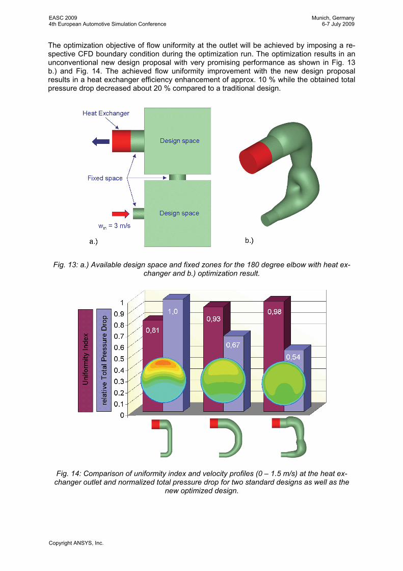
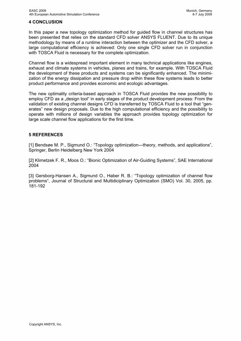
The optimization objective of flow uniformity at the outlet will be achieved by imposing a re-spective CFD boundary condition during the optimization run. The optimization results in an unconventional new design proposal with very promising performance as shown in Fig. 13 b.) and Fig. 14. The achieved flow uniformity improvement with the new design proposal results in a heat exchanger efficiency enhancement of approx. 10 % while the obtained total pressure drop decreased about 20 % compared to a traditional design.
Fig. 13: a.) Available design space and fixed zones for the 180 degree elbow with heat ex-changer and b.) optimization result.
Fig. 14: Comparison of uniformity index and velocity profiles (0 – 1.5 m/s) at the heat ex-changer outlet and normalized total pressure drop for two standard designs as well as the
new optimized design.
EASC 20094th European Automotive Simulation Conference
Munich, Germany6-7 July 2009
Copyright ANSYS, Inc.
4 CONCLUSION In this paper a new topology optimization method for guided flow in channel structures has been presented that relies on the standard CFD solver ANSYS FLUENT. Due to its unique methodology by means of a runtime interaction between the optimizer and the CFD solver, a large computational efficiency is achieved: Only one single CFD solver run in conjunction with TOSCA Fluid is necessary for the complete optimization. Channel flow is a widespread important element in many technical applications like engines, exhaust and climate systems in vehicles, planes and trains, for example. With TOSCA Fluid the development of these products and systems can be significantly enhanced. The minimi-zation of the energy dissipation and pressure drop within these flow systems leads to better product performance and provides economic and ecologic advantages. The new optimality criteria-based approach in TOSCA Fluid provides the new possibility to employ CFD as a „design tool“ in early stages of the product development process: From the validation of existing channel designs CFD is transferred by TOSCA Fluid to a tool that “gen-erates” new design proposals. Due to the high computational efficiency and the possibility to operate with millions of design variables the approach provides topology optimization for large scale channel flow applications for the first time. 5 REFERENCES [1] Bendsøe M. P., Sigmund O.: “Topology optimization—theory, methods, and applications”, Springer, Berlin Heidelberg New York 2004 [2] Klimetzek F. R., Moos O.: “Bionic Optimization of Air-Guiding Systems”, SAE International 2004 [3] Gersborg-Hansen A., Sigmund O., Haber R. B.: “Topology optimization of channel flow problems“, Journal of Structural and Multidiciplinary Optimization (SMO) Vol. 30, 2005, pp. 181-192
EASC 20094th European Automotive Simulation Conference
Munich, Germany6-7 July 2009
Copyright ANSYS, Inc.


![MULTIPHASE SIMULATION OF AUTOMOTIVE HVAC … · 2017. 3. 2. · [18] N. Bhagat and Shashi Kant, Amit Tiwari, Advanced Tool for Fluid Dynamics-CFD and its applications in Automotive,](https://static.fdocuments.net/doc/165x107/60e7b496445933579b25f286/multiphase-simulation-of-automotive-hvac-2017-3-2-18-n-bhagat-and-shashi.jpg)