CFD ANALYSIS OF SMOKE AND TEMPERATURE CONTROL …
15
Conference Extended Article – JTEN – 2014 –17 116 Journal of Thermal Engineering http://eds.yildiz.edu.tr/journal-of-thermal-engineering/Articles Yildiz Technical University Press, Istanbul, Turkey Manuscript Received August 28, 2014; Accepted September 05, 2014 Vol. 1, No. 2, pp. 116-130, April, 2015. This paper was recommended for publication in revised form by Regional Editor Derya Burcu Özkan CFD ANALYSIS OF SMOKE AND TEMPERATURE CONTROL SYSTEM OF AN INDOOR PARKING LOT WITH JET FANS A. Senveli Heat and Thermodynamics Division, Department of Mechanical Engineering, Yildiz Technical University (YTU), Yildiz, Besiktas, Istanbul 34349, Turkey T. Dizman Heat and Thermodynamics Division, Department of Mechanical Engineering, Yildiz Technical University (YTU), Yildiz, Besiktas, Istanbul 34349, Turkey A. Celen Heat and Thermodynamics Division, Department of Mechanical Engineering, Yildiz Technical University (YTU), Yildiz, Besiktas, Istanbul 34349, Turkey D. Bilge Heat and Thermodynamics Division, Department of Mechanical Engineering, Yildiz Technical University (YTU), Yildiz, Besiktas, Istanbul 34349, Turkey A. S. Dalkilic* Heat and Thermodynamics Division, Department of Mechanical Engineering, Yildiz Technical University (YTU), Yildiz, Besiktas, Istanbul 34349, Turkey S. Wongwises Fluid Mechanics, Thermal Engineering and Multiphase Flow Research Lab. (FUTURE), Department of Mechanical Engineering, King Mongkut’s University of Technology Thonburi (KMUTT), Bangmod, Bangkok 10140, Thailand Keywords: Normal Pollution Ventilation (NPV), Computational Fluid Dynamics (CFD), Jet Fans, Impulse Ventilation, Smoke and Heat Control (SHC) * Corresponding author: A.S. Dalkilic, Phone: +90 212 3832819, Fax: +90 212 2616659 E-mail address: [email protected] ABSTRACT The aim of this study is to perform analysis and interpretation of daily emission ventilation and fire ventilation system design in indoor parking lots with jet fans with the help of CFD program. In the study, ventilation of 8-story parking lot of a major business center in Istanbul with jet fans have been carried out, and the analysis on one story of this parking lot is provided as a case study. The airflow in all the regions of parking lot has been examined, the most suitable jet fan placements have been determined for daily emission and fire ventilation, and accuracy of this placement has been proved through the analysis with this study. The performed CFD analysis has enabled us to see correct placement of the jet fans and to intervene and decide the best placement. And for the fire case, the optimal results have been obtained by creating various scenarios in accordance with the international standards. It has been observed that the use of CFD analysis in the solution of the problem has allowed significant savings in time and money. 1. INTRODUCTION In the general overview of the ventilation systems of enclosed spaces in a building, it can be seen that the conditioned fresh air is fed to the atmosphere through many vents or diffusers by transferring via a channeling system from the ceiling level or a relatively higher level. This fresh air flown to the environment through vents and diffusers triggers the air movement in the atmosphere by the induction effect. A homogeneous air distribution and ambient comfort conditions are provided by mixing the fresh air with the ambient air in the area. As a basic principle, the exhausted polluted air is relatively unimportant since the amount of fresh air and supply points are kept under control.
Transcript of CFD ANALYSIS OF SMOKE AND TEMPERATURE CONTROL …

Conference Extended Article – JTEN – 2014 –17
116
Journal of Thermal Engineering http://eds.yildiz.edu.tr/journal-of-thermal-engineering/Articles Yildiz Technical University Press, Istanbul, Turkey Manuscript Received August 28, 2014; Accepted September 05, 2014
Vol. 1, No. 2, pp. 116-130, April, 2015.
This paper was recommended for publication in revised form by Regional Editor Derya Burcu Özkan
CFD ANALYSIS OF SMOKE AND TEMPERATURE CONTROL SYSTEM OF AN
INDOOR PARKING LOT WITH JET FANS
A. Senveli Heat and Thermodynamics
Division, Department of Mechanical Engineering, Yildiz
Technical University (YTU), Yildiz, Besiktas, Istanbul 34349,
Turkey
T. Dizman Heat and Thermodynamics
Division, Department of Mechanical Engineering, Yildiz
Technical University (YTU), Yildiz, Besiktas, Istanbul 34349,
Turkey
A. Celen Heat and Thermodynamics
Division, Department of Mechanical Engineering, Yildiz
Technical University (YTU), Yildiz, Besiktas, Istanbul 34349, Turkey
D. Bilge Heat and Thermodynamics
Division, Department of Mechanical Engineering, Yildiz
Technical University (YTU), Yildiz, Besiktas, Istanbul 34349,
Turkey
A. S. Dalkilic* Heat and Thermodynamics
Division, Department of Mechanical Engineering, Yildiz
Technical University (YTU), Yildiz, Besiktas, Istanbul 34349,
Turkey
S. Wongwises Fluid Mechanics, Thermal
Engineering and Multiphase Flow Research Lab. (FUTURE),
Department of Mechanical Engineering, King Mongkut’s
University of Technology Thonburi (KMUTT), Bangmod,
Bangkok 10140, Thailand
Keywords: Normal Pollution Ventilation (NPV), Computational Fluid Dynamics (CFD), Jet Fans, Impulse Ventilation, Smoke and Heat Control (SHC)
* Corresponding author: A.S. Dalkilic, Phone: +90 212 3832819, Fax: +90 212 2616659 E-mail address: [email protected]
ABSTRACT The aim of this study is to perform analysis and
interpretation of daily emission ventilation and fire ventilation
system design in indoor parking lots with jet fans with the help
of CFD program. In the study, ventilation of 8-story parking lot
of a major business center in Istanbul with jet fans have been
carried out, and the analysis on one story of this parking lot is
provided as a case study. The airflow in all the regions of
parking lot has been examined, the most suitable jet fan
placements have been determined for daily emission and fire
ventilation, and accuracy of this placement has been proved
through the analysis with this study. The performed CFD
analysis has enabled us to see correct placement of the jet fans
and to intervene and decide the best placement. And for the fire
case, the optimal results have been obtained by creating various
scenarios in accordance with the international standards. It has
been observed that the use of CFD analysis in the solution of
the problem has allowed significant savings in time and money.
1. INTRODUCTION In the general overview of the ventilation systems of
enclosed spaces in a building, it can be seen that the
conditioned fresh air is fed to the atmosphere through many
vents or diffusers by transferring via a channeling system from
the ceiling level or a relatively higher level. This fresh air flown
to the environment through vents and diffusers triggers the air
movement in the atmosphere by the induction effect. A
homogeneous air distribution and ambient comfort conditions
are provided by mixing the fresh air with the ambient air in the
area. As a basic principle, the exhausted polluted air is
relatively unimportant since the amount of fresh air and supply
points are kept under control.

Research Article
117
However, the designs and applications of parking lots are
based on obtaining a certain amount of circulation of the
parking lot volume per hour, through an exhaust based channel
system, for the last 20 years. The provision of fresh air to the
parking lots is considered relatively less important than the
exhaust system. The exhaust air volume is kept under control
indirectly for the amount of fresh air, leading to an indirect
control of fresh air. In general, the fresh air is taken from ramps,
openings or air shafts naturally. And in extreme cases, if there
aren’t sufficient natural openings in the parking lot, fresh air is
supplied to the parking lot via limited number of fresh air fans.
Ciro Caliendo et al.[1] studied the numerical simulation of
different HGV fire scenarios in curved bi-directional road
tunnels and safety evaluation. In their papers, the effects of
position of the HGV fire in the tunnel, tunnel geometry,
longitudinal ventilation of jet-fans, and the presence of traffic
flow on hot gas temperatures, air flow velocity, visibility
distance, toxic gases concentrations and the people evacuation
process are investigated deeply.
Nele Tilley et al.[2] executed the CFD study of relation
between ventilation velocity and smoke backlayering distance
in large closed car parks. They used a large set of (more than
350) CFD simulation as ‘numerical experiments’ from
parameter variation in the simulations. Three formulae have
been recommended on these topics as the critical inlet
velocity,the difference between inlet and outlet velocity and the
required ventilation velocity in the car park.
Yuan Jian-ping et al.[3] studied the numerical simulations
on sprinkler system and impulse ventilation in an underground
car park by using FDS code.Two cases with different
combinations of ventilation and sprinkler system have been
simulated to examine the effect of sprinkler system and impulse
ventilation during car park fires. They found that the impulse
ventilation system is very effective to control the smoke during
an underground car park fire.
In B. Merci and M. Shipp’s paper [4], they concentrated on
car park fire safety, more especially on fire and smoke (and
heat) dynamics. They investigated principally on the influence
of horizontal mechanical ventilation, a popular technique, on
the smoke and heat generated by the fire source. They
emphasized that the air flow momentum must be strong enough
to overcome the flow resistance caused by the fire-induced
smoke flow and the air flow must be able to reach the fire
source.
S. Lu et al. [5] investigated the smoke control capacity of
impulse ventilation system (IVS) in an underground car park.
They simulated 10 scenarios in a 80 m long, 40 m wide and 3.2
m height domain with a fire source simulating a car fire with an
peak heat release rate of 4 MW by using Fire Dynamic
Simulator version 5.30. Their results show that the smoke
control capacity of impulse ventilation system is sensitive to jet
fan numbers and increment in extract rate is conductive to relay
jet flows. They emphasized that high jet fan velocity may cause
severe smoke recirculation.
X.G. Zhang et al. [6] studied the fire spread and smoke
movement in a large underground car park under various fire
scenarios by using Fire Dynamic Simulator code. Their
simulated results show that the development of car fire in the
underground car park can be classified into four stages; (1)
initial stage, (2) developed stage, (3) extinction and re-burning
stage (4) fast-developed stage. They simulated the effect of
ventilation on the fire spread and smoke movement in a large
underground car park with 50 cars. They gave heat release rate,
oxygen and soot concentrations as well as temperature
distributions in their paper.
Joao Carlos Viegas [7] applied ventilation system for
covered car parks and used Impulse ventilation systems (IVS)
in order to control the smoke in the event of fire. He displayed
an analytical model for the flow field near the ceiling and
compared with CFD simulations.
X. Deckers et al. [8] benefitted from Computational Fluid
Dynamics (CFD) simulation and performed full-scale car park
fire experiments with smoke and heat control (SHC) by forced
mechanical horizontal ventilation. They investigated the
influence of the SHC system on the smoke movement in fire
conditions. They found that improving the smoke extraction rate
does not assist to take away the smoke if smoke is trapped
inside a recirculation region.
Ran Gao et al. [9] focused on the suggestion of the spread
of smoke in a huge transit terminal subway station in six
different fire-source locations with heat-release rates (HRRs) of
4 and 7.5 MW. They examined the effects of the natural and
mechanical ventilation in correlation with atrium height, roof
window, rate of air change, and fire-source locations. They
investigated the dispersion of fire-induced, buoyancy-driven
smoke in a subway station by applying the Large Eddy
Simulation (LES) simulation.
In case of a fire, the ventilation system has three different
tasks, according to the intended design. These are, supporting
firefighting teams in the evacuation of smoke in the parking lot
during or after fire, creation of smoke-free zones to enable
firefighting teams to step in the starting point of the fire, and to
ensure the safety of escape routes from the parking lot. In
general, natural ventilation, channeled mechanical ventilation
and jet fan systems are widely used in parking lot ventilation.
Although natural ventilation may be sufficient for open and
semi-open parking lots, channeled mechanical or jet fan
ventilation systems should be used in underground and closed
parking lots.
In this study, the ventilation and fire analysis of an 8-story
covered parking lot has been investigated with a CFD program
(Autodesk Simulation CFD) by dividing the area into zones. For
daily ventilation, optimum placements of the jet fans have been
determined thanks to CFD analysis as not to leave any dead
ventilation zones. Fire scenarios have been performed for
different places in the area according to the standards, and
comparisons have been made in terms of the smoke evacuation
time under different working conditions of jet fans (full
capacity/half capacity/off) for different zones. Change of speed,

Research Article
118
temperature, visibility and smoke emissions over time were
given separately for analyzed zones according to different fire
scenarios.
2. PRINCIPLES OF JET FAN VENTILATION SYSTEM In parking lots, after natural ventilation and channeled
mechanical ventilation the most commonly used third method is
known as jet fan ventilation and it's based on change of speed
phenomenon. The jet fan ventilation method is optimized
through continuous testing and integrated into the parking lot
security systems.
All air is drawn through fans and ducts in conventional
ventilation systems. This is performed for both the provided
fresh air and the discharged, used air. The airflow rate is kept as
low as possible to prevent pressure drop. However this means
that the channels should be relatively wide, and therefore
requires a larger area. But a different approach is used in jet
ventilation system. In this system, a small amount of air is
sucked into a fan and then it is discarded at a higher speed.
When the exhausted air hits the air in front of the fan, it pushes
that air forward and pulls the surrounding air at the same time.
In this way, all of the surrounding air is mobilized and moved
by 20-40 meters without using channels. Whole parking lot acts
as an air duct. The principle behind the jet ventilation system is
the same as that used in rockets where a small amount of air
(combustion products) are thrust at higher speeds to push the
rocket upwards. Space-saving, flexible installation, uniform air
distribution, effective ventilation in the parking lot, energy and
cost savings are among the advantages of the fan ventilation
system.
The performance of jet fans is expressed by using thrust.
The thrust, that is the force created by jet fans, is expressed as
Newton [N] and it’s the product of change in speed and mass
flow rate. In practical application, it is usually suggested that
the distance between the closest beams should be 0.5 meters at
the entrance and 2 meters at the exit for the highest yield, in jet
fan ventilation systems. Height of the beams should not be more
than 0.4 meters. Otherwise, the beam height must be
compensated either by hanging down the fans from the ceiling
or by increasing fan's distance between the nearest beam. All
energy is transported in the form of speed from the discharged
air to the environment, since the fan is fastened securely. Fan
remains in place when air is delivered forward. And as a result
of the drag, the amount of moving air will always be greater
than the amount of air passing through the fan. The amount of
moving air is the same in different sections of the facility.
Different speeds can be achieved in particular sections
depending on the size of the system. Not only the size and
number of jet fans depend on the size of the parking lot and its
plan but also the purpose of the system to be used for the CO
evacuation or smoke control.
In case of a fire, jet fans don't start immediately in
accordance with the required smoke evacuation speed, and will
remain off for a certain period of time, and then the fresh air
and exhaust fans run at maximum power. This allows people in
the parking lot to escape. Jet fans start to work after evacuation
of the building or arrival of firefighting, and push the air to
exhausters. This has two benefits. First, the smoke accumulates
within a relatively restricted space, and this allows detecting
fire's location and extinguishing. Second, it ensures that the
temperature is low near the fire, so firefighters can come closer
to the fire.
The smoke management refers to all measures that can be
taken one by one or in combination in order to reduce the
movement of smoke for the benefit of firefighting team and
goods. Certain measures taken with the help of fans during the
smoke evacuation: Control of smoke movements is provided by
making zoning, smoke extraction ducts, gates, chimneys or
using fire or smoke dampers and performing positive
pressurization, in the jet fan systems
3. NUMERICAL SAMPLE APPLICATION ON INDOOR
PARKING LOT OF A BUSINESS CENTER Autodesk Simulation CFD [10] program is used to apply
heat transfer and fluid flow analysis generally. Solution of the
flow and heat transfer problems encountered in industry can
take months via prototype, physical test, and trial-and-error
methods or with traditional (academic) CFD software. The
solution time of the flow and heat transfer problems can be
reduced from months to days, with Autodesk Simulation CFD
[10].
For this, the model or the environment to be analyzed
should be modeled with one of the computer-aided design
programs first. The created model is transferred and run in the
CFD program, and all of the rest of the work is performed and
completed with the CFD program. After opening the model in
the CFD program, a material should be assigned to each fluid
and volume, and there shouldn't be any volume left unassigned.
After this process, the boundary conditions are determined, for
example, all the necessary calculation values are entered such as
air intake and exhaust flow rate values at the point where jet
fans blowing air into the parking lot, zero pressure locations,
temperature inputs and outputs, and so on.
The last step and most important step before the solution is
the process called meshing. We can define mesh as the
following: It's the process of dividing a volume or surface area
into very small sections, to examine the movement of particles.
Meshing has a critical importance. If the number of meshes isn't
set well, we cannot obtain the desired results. For example, if
too much mesh number is given, the computer will have
difficulty in the solution and the solution time becomes longer
unnecessarily. Or if we give too low mesh number, the result of
the analysis may not be accurate as desired. Therefore, the fine-
tune of the number of mesh is an important stage of the analysis
process. Details of the mesh used in the analysis are shown in
Figure 1.
The last step is the solution stage. Values to be entered and
wanted results are selected and the number of iterations is
determined. Determining the correct number of iterations is also
critical in the analysis. Iteration is the process to use previous

Research Article
119
Figure 1 - Proper Mesh Transitions between different parts
output in the calculation as the input in the next calculation in
order to successively converge to the result. Simply, accuracy of
the result directly proportional to the number of iterations, but
too much iteration will increase the analysis time unnecessarily.
The parking lot of the analyzed business center consists of
8 floors, including PB1, PB2A, PB2, PB3, PB4, PB5, PB6 and
PB7. This parking lot has been divided into specific zones and
the CFD simulation has been performed as if these zones are
separate parking lots. The model of the analyzed parking lot is
shown in Figure 2.
The smoke is spread other floors and regions from the fire
location, then it can cause damage and death in these places. In
recent years, zone (region) control methods have been
developed to prevent movement of the smoke. The purpose here
is to divide the building into pressure zones as shown in Figure
3, and control the movement of smoke. Smoke is sucked and
exhausted from the fire area with the help of mechanical
ventilation system; fresh air is pumped into the other areas.
Zones should also be isolated well from air leaks and airflow, in
order to obtain the desired result in the system. In this system,
the exhaust of the smoke from the fire area also prevents the
excessive pressure increases in the fire area caused by thermal
expansion seen before.
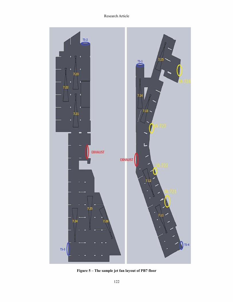
Figures 4 and 5 show an example layout of a jet fan in the
examined parking lot. The discharge unit consists of a screen,
an aspirator and, if necessary, a noise-block in general. When
the set limit is exceeded, the aspirator starts first, and then the
jet fans start to work. In outdoor parking lots, where no
ventilation system is required, it's possible to support natural
ventilation with jet fans. This prevents the formation of "dead"
areas. This is also valid for other parking lots, which cannot
meet the outdoor parking lot requirements with a very small
margin. The relevant conditions can be met by making use of jet
fans only in this type of facilities. In such cases, the best
solution is the use of 100% reversible axial fans. These fans can
provide thrust in both directions. Thus, the direction of flow can
be changed according to wind conditions.
As shown in Figure 6; the exhaust fans are working with a
single exhaust shaft from PB2A to PB7, and this transfer
discharges the exhaust gases. These fans are shown in red on
the CFD model. As shown in Figure 7, the fresh air fans are
working with 3 different fresh air shafts from PB2A to PB7, and
these fans are shown in blue on the CFD model.
Fresh air will be sent to all floors with mechanical
ventilation. However, the fresh air can pass naturally through
gates where the parking lot floors are connected to other floors
and entrance-exit ramps.
4. RESULTS AND DISCUSSION The ventilation of parking lots are usually designed for the
removal of smoke in case of fire, and limiting CO and other
emissions of vehicles. The present ventilation system is used for
both cases usually. The purpose of the ventilation is to
discharge harmful gases as soon as possible or to rarefy their
ratio in the environment.
CFD analysis has been performed for Daily Emission
Ventilation (NPV - Negative Pressure Ventilation) and
Emergency Mode (EM) for all of the floors. 5-air-exchanges
has been used for the Daily Emission Ventilation and 10-air-
exchanges has been used for the Emergency Mode, according to
ASHRAE[11]'sheating, ventilation and air-conditioning
standards. All jet fans are set to perform daily emission
ventilation (NPV) and they start in all zones at the same time to
perform 5 air exchanges per hour. The blowing distances of jet
fans are chosen as to create airflow in the environment and to
transfer the air coming from fresh air fans to the exhaust areas.
A conversion factor is applied for the local pollution caused by
movements of cars in their own area. The adjustment for air
dampers for these local air exchange requirements can be
performed periodically. This local exchange is an entirely
optional decision based on analysis results.
The volumetric flow rates, NPV flow rates, EM volumetric
flow rates, EM flow rates in the exhaust and fresh air shafts
computed by considering the above mentioned air exchange
coefficients for all floors according to usage areas of each floor
is shown in Table 1 and Table 2. The floor height is accepted as
3 m on average in the calculation of these values.
The area has been divided into zones first, and the daily
emission ventilation analysis has been performed for steady
state and the fire analysis has been performed for transient
cases, by designing different scenarios in the zones. The most
appropriate results for analyzing the airflow are air velocities
and LMA (Local Mean Age). In the LMA analysis no
recirculation is desired in any of the zones. The desired
parameter for LMA in Daily Emission Ventilation (NPV)
analysis is 950 seconds. Again for the LMA, this parameter is
360 seconds (approximately 10 air changes) in the Emergency
Mode (EM). The air speeds denote air distribution and air
movement throughout the parking lot. In the analysis of airflow
rate, areas without airflow are not desired in Daily Emission
ventilation (NPV) and Emergency Mode (EM). Desired airflow

Research Article
120
Figure 2 –The model of car-park
Figure 3 – Smoke control zones for PB7 floor

Research Article
121
Figure 4 -Jet fan layout for PB4 Zone-1 and 2
Research Article
122
Figure 5 – The sample jet fan layout of PB7 floor

Research Article
123
rate is 0.1 m/s or at higher speeds, and results suitable to
this have been obtained.
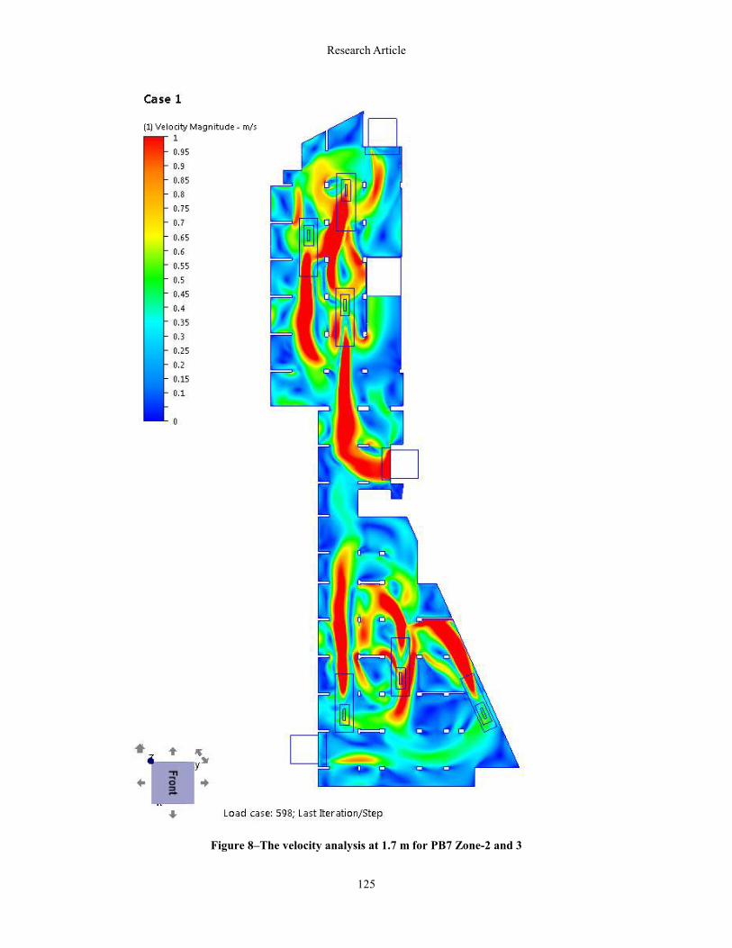
As can be seen in Figure 8, no areas observed with stagnant
airflow in parking lot and walking paths in the daily emission
ventilation. One of the most important results to be examined in
terms of NPV analysis, the LMA (Local Mean Age), that is the
average period of time for air particles to stay in the
environment. This is because; the purpose in NPV ventilation is
to discharge CO particles at certain time intervals. As can be
seen in Figure 9, there were no stationary air particles was
observed, staying more than the optimum period, when looking
at the LMA result of the analyzed floor. These are acceptable
results, since the LMA values are in the desired range.
A fire scenario with a fire sprinkler system having 4MW of
power, 14m length and 2x5 m dimension has been designed, in
accordance with the standards in time-dependent fire analysis.
The fire simulation has been performed for PB7 floor Zone 3. 3
pieces of jet fans is seen in Figure 10, and the size of fire exit is
5x2 m.
It's revealed by our analysis performed for fire cases in parking
lot regions that analysis is required, where we have stopped the
transfer of smoke to the other zones and confined and
discharged the smoke in a single zone. It's very important for
firefighting team to reach the fire area, in order to extinguish the
fire and perform the evacuation of people without any hustle in
those areas, by preventing smoke to spread to other zones
during fire ignition, its growth, flares, fully developed fire, and
extinguishing, in the fire zone. The type of solution to prevent
spreading of smoke to other zones is revealed in the analysis
results.
In order to prevent the spread of fire from the floor in fire
to other floors, the shafts are closed and isolated from this floor,
Table 1 –The details of mechanical exhaust ventilation
shafts
Floors
NPV
flow
rate
(m3/h)
Area
(m2)
NPV
flow
velocity
(m/s)
EM flow
rate (m3/h)
EM
flow
velocity
(m/s)
PB2A 44.928 4,20 2,97 212.000 14,02
PB2 42.912 4,20 2,84 212.000 14,02
PB3 43.584 4,20 2,88 212.000 14,02
PB4 50.285 4,20 3,33 212.000 14,02
36.269 4,20 2,40 212.000 14,02
PB5 63.475 4,20 4,20 212.000 14,02
65.971 4,20 4,36 212.000 14,02
PB6 72.307 4,20 4,78 212.000 14,02
53.626 4,20 3,55 212.000 14,02
PB7 42.232 4,20 2,79 212.000 14,02
32.532 4,20 2,15 212.000 14,02
Table 2 - The properties of fresh air shafts
Floors
Usage
Area
(m2)
NPV
flow
rate
(m3/h)
NPV
flow
velocity
(m/s)
EM flow
rate
(m3/h)
EM
flow
velocity
(m/s)
PB2A 4,20 13.478 0,89 100.000 6,61
4,20 13.478 0,89 100.000 6,61
PB2 4,20 12.874 0,85 100.000 6,61
4,20 12.874 0,85 100.000 6,61
PB3 4,20 13.075 0,86 100.000 6,61
4,20 13.075 0,86 100.000 6,61
PB4 4,20 15.085 1,00 100.000 6,61
4,20 15.085 1,00 100.000 6,61
2,80 21.761 2,16 67.000 6,65
PB5
4,20 18.156 1,20 100.000 6,61
4,20 21.427 1,42 67.000 4,43
4,20 21.496 1,42 100.000 6,61
2,80 16.589 1,65 58.000 5,75
PB6
4,20 17.971 1,19 100.000 6,61
4,20 14.204 0,94 67.000 4,43
4,20 21.335 1,41 100.000 6,61
2,10 22.049 2,92 58.000 7,67
PB7
4,20 18.236 1,21 100.000 6,61
4,20 14.296 0,95 67.000 4,43
4,20 20.229 1,34 100.000 6,61
2,10 22.003 2,91 58.000 7,67
to block spread of smoke in exhaust shafts and fresh air shafts.
And in the floor, working capacities of jet fans, fresh air and
exhaust fans becomes two times the daily emission ventilation
capacity, and all the power is used for the evacuation of smoke,
during the fire. In addition to this, operation of jet fans in the
adjacent zone prevents spread of smoke. In the time-dependent
analysis we've performed at this point we can obtain the ability
to make comments on whether the jet fans and fresh air fans at
the other zones should operate or not. The analysis results we've
obtained from various scenarios show us that we have obtained
the desired results, and the jet fans in the other zones operate at
half capacity and prevent the spread of smoke, by creating
airflow and an air block in the exhaust area used by other zones
in common. The results we've obtained in other scenarios have
presented that smoke is spread to adjacent zone

Research Article
124
Figure 6 - Exhaust shaft
Figure 7–The zones of fresh air shaft
Research Article
125
Figure 8–The velocity analysis at 1.7 m for PB7 Zone-2 and 3

Research Article
126
Figure 9 – Local Mean Age (LMA) analysis at 1.7 m for PB7 Zone-2 and 3

Research Article
127
Figure 10 –The position of fire source
in this case (for example, in cases of nonoperational jet fans in
the other zone or the operation of fresh air fan only, not the jet
fans). Therefore, jet fans and fresh air fans at the neighboring
zones should be operated for the discharge of smoke quickly,
before spreading to the neighboring zones.
4.1 Main Scenario - Evaluations
In this scenario, it's assumed that all the fans are working at full
capacity, since the fire has been started in Zone 1. Fresh air fans
and jet fans are not working in the adjacent zone Zone 2, and
the analysis has been continued by assumed that the fire will
continue for 3 minutes at 4MW of power, and will stop
gradually.
In this scenario, the power has been reached to 4MW in 123
seconds, and continued for 3 minutes at the same power, in the
fire started at Zone 1. Later, the fire has been stopped gradually,
and the analysis results have been obtained.
Development of the fire, temperature, velocity and smoke
distributions is given in the Figure 12 for 60 second after the
start of fire, and in Figure 12 for after 550 seconds.
As a result of this analysis it's seen that smoke and heat
energy of a 3 minutes of fire started in Zone 3 will escape to
Zone 2, at 4MW.
It should be noted that detailed analyses on this subject
can be seen from authors’ publication [12].

Research Article
128
60 s – 1,5MW
Figure 11–Analysis results at 1.75 m (Velocity, Temperature distributions, Smoke spread) – 60s

Research Article
129
550 s – 0 MW
Figure 12 –Analysis results at 1.75 m (Velocity, Temperature distributions, Smoke spread)–550s

Research Article
130
5. CONCLUSION The CFD analysis performed in the study has a great
importance in terms of daily emission ventilation, fire and
smoke control ventilation, in indoor parking lots. It enables to
create safe areas by evacuating smoke as soon as possible and
control of hazards in advance. In addition, temperature, air flow
rate, smoke density and visibility can be checked separately in
any section of the parking lot for any time interval, and it's also
seen that this gives us results in comply with the standards.
According to the analysis results, it's observed that the
airflow has been created effectively by the placement of jet fans
at optimum locations correctly. The dead zones have been
eliminated, where there were no air exchanges, in the daily
emission ventilation including the indented areas in the parking
lot, with the formation of airflow. It is obvious that there will be
economically large returns when the desired results have been
obtained in the analysis by using models of jet fan placements
in tight spaces at different air flow rates.
NOMENCLATURE
LMA Local Mean Age
IVS Impulse Ventilation System
SHEVS Smoke and Heat Exhaust Ventilation System
SHC Smoke and Heat Control
HRR Heat Release Rate
LES Large Eddy Simulation
FDS Fire Dynamics Simulator (Software)
NPV Normal Pollution Ventilation
EM Emergency Mode
ACKNOWLEDGMENTS The authors are grateful to the company of Afs Boru Sanayi
A.Ş. for their contributions to this study.
REFERENCES
1. Caliendo C., Ciambelli P., Guglielmo M., Meo M. and
Russo P., “Numerical simulation of different HGV fire
scenarios in curved bi-directional road tunnels and
safety evaluation’’, Tunnelling and Underground Space
Technology, Vol. 31, pp. 33–50, 2012.
2. Tilley N., Deckers X.. and Merci B., ‘’CFD study of
relation between ventilation velocity and smoke
backlayering distance in large closed car parks,’’ Fire
Safety Journal, Vol. 48, pp. 11–20, (2012).
3. Jian-ping Y., Zheng F., Zhi T. and Jia-yun S.,
‘’Numerical Simulations on Sprinkler System and
Impulse Ventilation in an Underground Car Park’’,
Procedia Engineering, Vol. 11, pp. 634–639, 2011.
4. Merci B. and Shipp M., ‘’Smoke and heat control for
fires in large car parks: Lessons learnt from research’’,
Fire Safety Journal, “Article in Press”.
5. Lu S., Wang Y.H., Zhang R.F. and Zhang H.P.,
‘’Numerical Study on Impulse Ventilation for Smoke
Control in an Underground Car Park’’, Procedia
Engineering, Vol. 11, pp. 369–378, 2011.
6. Zhang X.G., Guo Y.C., Chan C.K. and Lin W.Y.,
‘’Numerical simulations on fire spread and smoke
movement in an underground car park’’, Building and
Environment, Vol. 42, pp. 3466–3475, 2007.
7. Viegas J., ‘’The use of impulse ventilation for smoke
control in underground car parks’’, Tunnelling and
Underground Space Technology, Vol. 25, pp. 42–53,
2010.
8. Deckers X., Haga S., Tilley N. and Merci B., ‘’Smoke
control in case of fire in a large car park: CFD
simulations of full-scale configurations’’, Fire Safety
Journal, “Article in Press”.
9. Gao R., Li A., Hao X., Lei W. and Deng B.,
‘’Prediction of the spread of smoke in a huge transit
terminal subway station under six different fire
scenarios’’, Tunnelling and Underground Space
Technology, Vol. 31, pp. 128–138, 2012.
10. Autodesk Simulation CFD, Autodesk, Inc., 111
McInnis Parkway San Rafael, CA 94903 Available
from: http://usa.autodesk.com/
11. ASHRAE Handbook: HVAC Application 1995.
Atlanta, Ga.,U.S.A.: American Society of Heating,
Refrigeration and Airconditioning Engineers.
12. Dalkilic A.S., Kundu B., Celen A., Atayilmaz S.O.,
Kayaci N. and Wongwises S., ‘’Smoke control of a car
park by means of CFD analyses using jet fans, ASME
2014 Fluids Engineering Summer Meeting August 3-7,
USA, 2014.