CFD ANALYSIS OF DOUBLE HELICAL PIPE PARALLEL& COUNTER …ijpres.com/pdf35/50.pdf · tube, double...
12
INTERNATIONAL JOURNAL OF PROFESSIONAL ENGINEERING STUDIES Volume 9 /Issue 2 / OCT 2017 IJPRES CFD ANALYSIS OF DOUBLE HELICAL PIPE PARALLEL& COUNTER FLOW HEAT EXCHANGER 1 Hepsiba Sudarsanam, 2 Dvsrbm Subhramanyam 1 PG Scholar, Department of MECH, Nalanda Institute of Technology, Kantepudi,Sattenapalli Dist.: Guntur, A.P, India,Pin: 522403 E-Mail Id: [email protected] 2 Asst professor, Department of MECH, Nalanda Institute of Technology, Kantepudi,Sattenapalli Dist.:Guntur,A.P, India,Pin: 522403 E-Mail Id:[email protected] Abstract A heat exchanger is a device that is used to transfer thermal energy (enthalpy) between two or more fluids between a solid surface and a fluid, or between solid particulates and a fluid, at distinctive temperatures and in thermal contact. Heat exchangers are important engineering devices in many process industries since the efficiency and economy of the process largely depend on the performance of the heat exchangers. A helical coil heat exchanger has a wide range of application in industries over the straight and shell type heat exchangers because of its greater heat transfer area, mass transfer coefficient and higher heat transfer capability, etc. The relevance of helical coil heat exchanger has been identified in industrial application like turbine power plants, automobile, aerospace, etc. because of above mentioned factors. Double helical pipe is modeled by using solid works 2016 software & CFD analysis has been done for varying inlet condition keeping the heat flux of outer wall constant. Steel was used as the base metal for both inner and outer pipe and simulation has been done using ANSYS 14.5. The software ANSYS 14.5 work bench was used to plot the temperature contour, velocity contour and total heat dissipation rate taking cold fluid at constant velocity in the outer tube and hot fluid with varying velocity in the inner one. Water was taken as the working fluid for both inner and outer tube. Aim of the Present Work The design of a helical coil tube in tube heat exchanger has been facing problems because of the lack of experimental data available regarding the behavior of the fluid in helical coils and also in case of the required data for heat transfer, unlike the Shell & Tube Heat exchanger. So to the best of our effort, numerical analysis was carried out to determine the heat transfer characteristics for a double-pipe helical heat exchanger by varying the different parameters like different temperatures and diameters of pipe and coil and also to determine the fluid flow pattern in helical coiled heat exchanger. The objective of the project is to obtain a better and more quantitative insight into the heat transfer process that occurs when a fluid flows in a helically coiled tube. The study also covered the different types of fluid flow range extending from laminar flow through transition to turbulent flow. The materials for the study were decided and fluid taken was water and the material for the pipe was taken to be steel for its better conducting properties
Transcript of CFD ANALYSIS OF DOUBLE HELICAL PIPE PARALLEL& COUNTER …ijpres.com/pdf35/50.pdf · tube, double...

INTERNATIONAL JOURNAL OF PROFESSIONAL ENGINEERING STUDIES Volume 9 /Issue 2 / OCT 2017
IJPRES
CFD ANALYSIS OF DOUBLE HELICAL PIPE PARALLEL& COUNTER FLOW
HEAT EXCHANGER 1Hepsiba Sudarsanam, 2Dvsrbm Subhramanyam
1 PG Scholar, Department of MECH, Nalanda Institute of Technology, Kantepudi,Sattenapalli
Dist.: Guntur, A.P, India,Pin: 522403
E-Mail Id: [email protected] 2Asst professor, Department of MECH, Nalanda Institute of Technology, Kantepudi,Sattenapalli
Dist.:Guntur,A.P, India,Pin: 522403
E-Mail Id:[email protected] Abstract
A heat exchanger is a device that is used to transfer
thermal energy (enthalpy) between two or more
fluids between a solid surface and a fluid, or between
solid particulates and a fluid, at distinctive
temperatures and in thermal contact. Heat exchangers
are important engineering devices in many process
industries since the efficiency and economy of the
process largely depend on the performance of the
heat exchangers.
A helical coil heat exchanger has a wide range of
application in industries over the
straight and shell type heat exchangers because of its
greater heat transfer area, mass
transfer coefficient and higher heat transfer
capability, etc. The relevance of helical coil
heat exchanger has been identified in industrial
application like turbine power plants,
automobile, aerospace, etc. because of above
mentioned factors.
Double helical pipe is modeled by using solid works
2016 software & CFD analysis has been done for
varying inlet condition keeping the heat flux of outer
wall constant. Steel was used as the base metal for
both inner and outer pipe and simulation has been
done using ANSYS 14.5. The software ANSYS 14.5
work bench was used to plot the temperature contour,
velocity contour and total heat dissipation rate taking
cold fluid at constant velocity in the outer tube and
hot fluid with varying velocity in the inner one.
Water was taken as the working fluid for both inner
and outer tube.
Aim of the Present Work
The design of a helical coil tube in tube heat
exchanger has been facing problems because of the
lack of experimental data available regarding the
behavior of the fluid in helical coils and also in case
of the required data for heat transfer, unlike the Shell
& Tube Heat exchanger. So to the best of our effort,
numerical analysis was carried out to determine the
heat transfer characteristics for a double-pipe helical
heat exchanger by varying the different parameters
like different temperatures and diameters of pipe and
coil and also to determine the fluid flow pattern in
helical coiled heat exchanger. The objective of the
project is to obtain a better and more quantitative
insight into the heat transfer process that occurs when
a fluid flows in a helically coiled tube. The study also
covered the different types of fluid flow range
extending from laminar flow through transition to
turbulent flow. The materials for the study were
decided and fluid taken was water and the material
for the pipe was taken to be steel for its better
conducting properties
Gurmeet
Typewritten Text
369

INTERNATIONAL JOURNAL OF PROFESSIONAL ENGINEERING STUDIES Volume 9 /Issue 2 / OCT 2017
IJPRES
Boundary conditions
Cold Inlet velocity: 2 m/s
Hot inlet velocity: 1.8 m/s
Cold inlet temperature: 303 k
Hot inlet temperature: 353 k
Cold outlet: pressure outlet
Hot outlet: pressure outlet
Hot & cold fluid: water
Inner & outer Pipe material: steel
Introduction
A heat exchanger is a device used to transfer
heat between one or more fluids. The fluids may be
separated by a solid wall to prevent mixing or they
may be in direct contact. They are widely used in
space heating, refrigeration, air conditioning, power
stations, chemical plants, petrochemical
plants, petroleum refineries, natural-gas processing,
and sewage treatment. The classic example of a heat
exchanger is found in an internal combustion
engine in which a circulating fluid known as engine
coolant flows through radiator coils andair flows past
the coils, which cools the coolant and heats the
incoming air.
Heat exchangers are one of the mostly used
equipment in the process industries. Heat exchangers
are used to transfer heat between two process
streams. One can realize their usage that any process
which involve cooling, heating, condensation, boiling
or evaporation will require a heat exchanger for these
purpose. Process fluids, usually are heated or cooled
before the process or undergo a phase change.
Different heat exchangers are named according to
their application. For example, heat exchangers being
used to condense are known as condensers, similarly
heat exchanger for boiling purposes are called
boilers. Performance and efficiency of heat
exchangers are measured through the amount of heat
transfer using least area of heat transfer and pressure
drop. A better presentation of its efficiency is done
by calculating over all heat transfer coefficient.
Pressure drop and area required for a certain amount
of heat transfer, provides an insight about the capital
cost and power requirements (Running cost) of a heat
exchanger. Usually, there is lots of literature and
theories to design a heat exchanger according to the
requirements.
The most important fluid flow heat exchangers are
HVAC, process industry, refrigeration etc. The
purpose of constructing a heat exchanger is to get an
efficient method of heat transfer from one fluid to
another, by direct contact or by indirect contact.
There are three mode of heat transfer 1.Conduction
2.Convection 3.Radiation.Heat transfer is negligible
in radiation as compare to conduction and
convection. Conduction takes place when the heat
from the high temperature fluid flows through the
surrounding solid wall. The conductive heat transfer
can be maximized by selecting a minimum thickness
of wall of a highly conductive material. But
convection is plays the major role in the performance
of a heat exchanger. Forced convection in a heat
exchanger transfers the heat from one moving stream
to another stream through the wall of the pipe. The
cooler fluid removes heat from the hotter fluid as it
flows along or across it
Heat exchangers are important engineering devices in
many process industries since the efficiency and
economy of the process largely depend on the
performance of the heat exchangers. High
performance heat exchangers are, therefore, very
much required. Improvement in the performance may
result in the reduction in the size of the heat
exchangers of a fixed size can give an increased heat
transfer rate, it might also give a decrease in
Gurmeet
Typewritten Text
370
INTERNATIONAL JOURNAL OF PROFESSIONAL ENGINEERING STUDIES Volume 9 /Issue 2 / OCT 2017
IJPRES
temperature difference between the process fluids
enabling efficient utilization of thermodynamic
availability. This is particularly true for Laminar flow
since the heat transfer coefficients for laminar
straight flow through a plain tube is very low. Forced
convection heat transfer in doubly connected ducts
bounded externally by a circle and internally by a
rectangular polygon of various shapes was analyzed
using a finite element method.
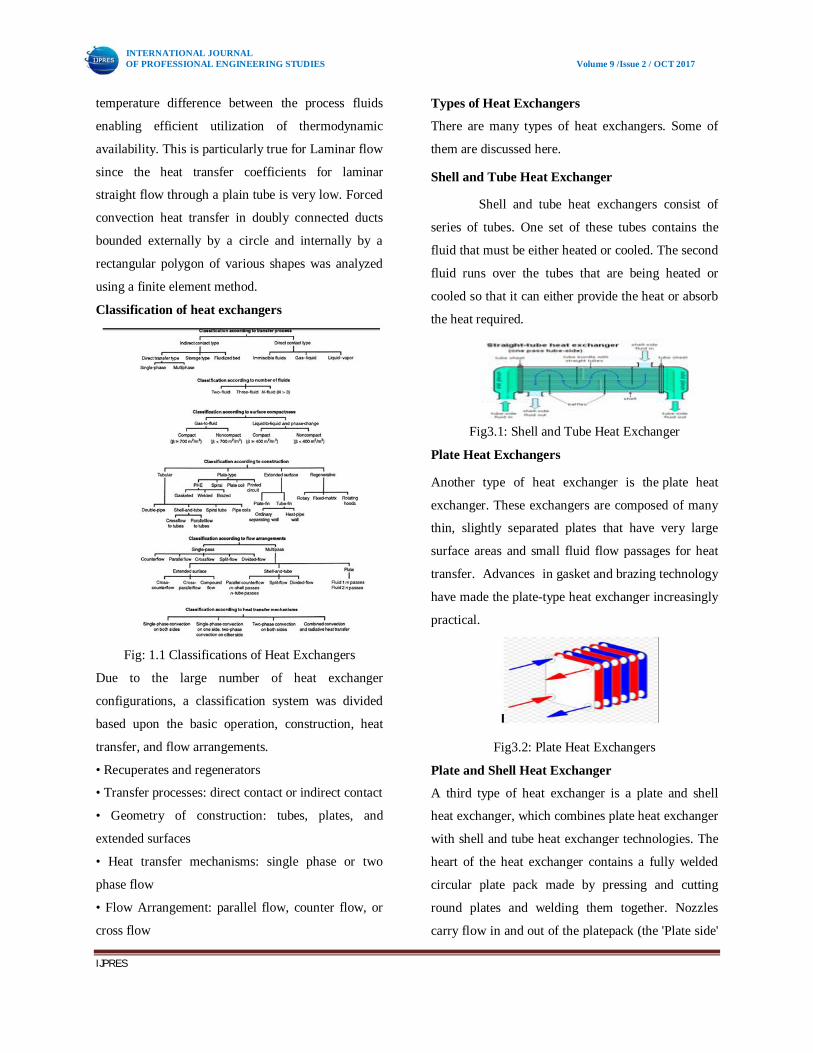
Classification of heat exchangers
Fig: 1.1 Classifications of Heat Exchangers
Due to the large number of heat exchanger
configurations, a classification system was divided
based upon the basic operation, construction, heat
transfer, and flow arrangements.
• Recuperates and regenerators
• Transfer processes: direct contact or indirect contact
• Geometry of construction: tubes, plates, and
extended surfaces
• Heat transfer mechanisms: single phase or two
phase flow
• Flow Arrangement: parallel flow, counter flow, or
cross flow
Types of Heat Exchangers
There are many types of heat exchangers. Some of
them are discussed here.
Shell and Tube Heat Exchanger
Shell and tube heat exchangers consist of
series of tubes. One set of these tubes contains the
fluid that must be either heated or cooled. The second
fluid runs over the tubes that are being heated or
cooled so that it can either provide the heat or absorb
the heat required.
Fig3.1: Shell and Tube Heat Exchanger
Plate Heat Exchangers
Another type of heat exchanger is the plate heat
exchanger. These exchangers are composed of many
thin, slightly separated plates that have very large
surface areas and small fluid flow passages for heat
transfer. Advances in gasket and brazing technology
have made the plate-type heat exchanger increasingly
practical.
Fig3.2: Plate Heat Exchangers
Plate and Shell Heat Exchanger
A third type of heat exchanger is a plate and shell
heat exchanger, which combines plate heat exchanger
with shell and tube heat exchanger technologies. The
heart of the heat exchanger contains a fully welded
circular plate pack made by pressing and cutting
round plates and welding them together. Nozzles
carry flow in and out of the platepack (the 'Plate side'
Gurmeet
Typewritten Text
371
INTERNATIONAL JOURNAL OF PROFESSIONAL ENGINEERING STUDIES Volume 9 /Issue 2 / OCT 2017
IJPRES
flow path). The fully welded plate pack is assembled
into an outer shell that creates a second flow path (
the 'Shell side'). Plate and shell technology offers
high heat transfer, high pressure, high operating
temperature, puling and close approach temperature.
In particular, it does completely without gaskets,
which provides security against leakage at high
pressures and temperatures.
Fig3.3: Plate and Shell Heat Exchanger
Theory of Design and Analysis Design
Considerations
In designing heat exchangers, a number of factors
that need to be considered are:
1. Resistance to heat transfer should be minimized
2.Contingencies should be anticipated via safety
margins; for example, allowance for fouling during
operation.
3. The equipment should be sturdy.
4. Cost and material requirements should be kept
low.
5. Corrosion should be avoided.
6. Pumping cost should be kept low.
7. Space required should be kept low.
8. Required weight should be kept low.
Classification of Heat Exchangers According To
the Flow Direction
a) Parallel flow
b) Cross flow
c) Counter flow
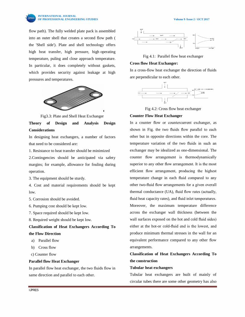
Parallel flow Heat Exchanger
In parallel flow heat exchanger, the two fluids flow in
same direction and parallel to each other.
Fig 4.1: Parallel flow heat exchanger
Cross flow Heat Exchanger:
In a cross-flow heat exchanger the direction of fluids
are perpendicular to each other.
Fig 4.2: Cross flow heat exchanger
Counter Flow Heat Exchanger
In a counter flow or countercurrent exchanger, as
shown in Fig. the two fluids flow parallel to each
other but in opposite directions within the core. The
temperature variation of the two fluids in such an
exchanger may be idealized as one-dimensional. The
counter flow arrangement is thermodynamically
superior to any other flow arrangement. It is the most
efficient flow arrangement, producing the highest
temperature change in each fluid compared to any
other two-fluid flow arrangements for a given overall
thermal conductance (UA), fluid flow rates (actually,
fluid heat capacity rates), and fluid inlet temperatures.
Moreover, the maximum temperature difference
across the exchanger wall thickness (between the
wall surfaces exposed on the hot and cold fluid sides)
either at the hot-or cold-fluid end is the lowest, and
produce minimum thermal stresses in the wall for an
equivalent performance compared to any other flow
arrangements. Classification of Heat Exchangers According To
the construction
Tubular heat exchangers
Tubular heat exchangers are built of mainly of
circular tubes there are some other geometry has also
Gurmeet
Typewritten Text
372

INTERNATIONAL JOURNAL OF PROFESSIONAL ENGINEERING STUDIES Volume 9 /Issue 2 / OCT 2017
IJPRES
been used in different applications. This design can
be modified by length, diameter and physical
arrangement. This type is used for liquid-to-liquid
(phase changing like condensing or evaporation) heat
transfer. Again this type is classified into shell and
tube, double pipe and spiral tube heat exchangers.
Double pipe heat exchanger
The double pipe or the tube in tube type heat
exchanger consists of one pipe placed concentrically
inside another pipe having a greater diameter. The
flow in this configuration can be of two types:
parallel flow and counter-flow. It can be arranged in
a lot of series and parallel configurations to meet the
different heat transfer requirements. Double coil heat
exchanger is widely used; knowledge about the heat
transfer coefficient, pressure drop, and different flow
patterns has been of much importance. The curvature
in the tubes creates a secondary flow, which is
normal to the primary axial direction of flow. This
secondary flow increases the heat transfer between
the wall and the flowing fluid. And they offer a
greater heat transfer area within a small space, with
greater heat transfer coefficients. The two basic
boundary conditions that are faced in the applications
are constant temperature and the constant heat flux of
the wall
Double pipe helical coil Close-up of double pipe
coil
Materials Used For Heat Exchangers
A variety of materials are used in the design
of tube heat exchangers, including carbon steel,
stainless steel, copper, bronze, brass, titanium and
various alloys. Generally, the outer shell is made of a
durable, high strength metal, such as carbon steel or
stainless steel. Inner tubes require an effective
combination of durability, corrosion resistance and
thermal conductivity. Regular materials used in their
construction are copper, stainless steel, and
copper/nickel alloy. Other metals are used in device
fittings, end bonnets and heads.
Heat Transfer Coefficient
Convective heat transfer is the transfer of heat from
one place to another by the movement of fluids due
to the difference in density across a film of the
surrounding fluid over the hot surface. Through this
film heat transfer takes place by thermal conduction
and as thermal conductivity of most fluids is low, the
main resistance lies there. Heat transfer through the
film can be enhanced by increasing the velocity of
the fluid flowing over the surface which results in
reduction in thickness of film. The equation for rate
of heat transfer by convection under steady state is
given by,
Wall convection
Gurmeet
Typewritten Text
373

INTERNATIONAL JOURNAL OF PROFESSIONAL ENGINEERING STUDIES Volume 9 /Issue 2 / OCT 2017
IJPRES
The value of ‘h’ depends upon the properties of fluid
within the film region; hence it
is called ‘Heat Transfer Coefficient’. It depends on
the different properties of fluid, dimensions of the
surface and velocity of the fluid flow (i.e. nature of
flow). The overall heat transfer coefficient is the
overall transfer rate of a series or parallel
combination of convective and conductive walls. The
‘overall Heat Transfer Coefficient’ is expressed in
terms of thermal resistances of each fluid stream. The
summation of individual resistances is the total
thermal resistance and its inverse is the overall heat
transfer coefficient, U.
Where, U = overall heat transfer coefficient based on
outside area of tube all
A = area of tube wall
h = convective heat transfer coefficient
Rf = thermal resistance due to fouling
Rw= thermal resistance due to wall conduction and
suffixes ‘O’ and ‘I’ refer to the outer and inner tubes,
respectively.
Due to existence of the secondary flow, the heat
transfer rates (& the fluid pressure drop) are greater
in the case of a curved tube than in a corresponding
straight tube at the same flow rate and the same
temperature and same boundary conditions.
SOLID WORKS
Solid Works is mechanical design
automation software that takes advantage of the
familiar Microsoft Windows graphical user interface.
It is an easy-to-learn tool which makes it
possible for mechanical designers to quickly sketch
ideas, experiment with features and dimensions, and
produce models and detailed drawings.
Modeling of double helical pipe heat exchanger
Make sketch for helix
Make helix by giving pitch and revolution
Pitch: 40mm
Revolution: 2
Use sweep feature command and generate inner pipe
Use shell command and give thickness to pipe
Gurmeet
Typewritten Text
374
INTERNATIONAL JOURNAL OF PROFESSIONAL ENGINEERING STUDIES Volume 9 /Issue 2 / OCT 2017
IJPRES
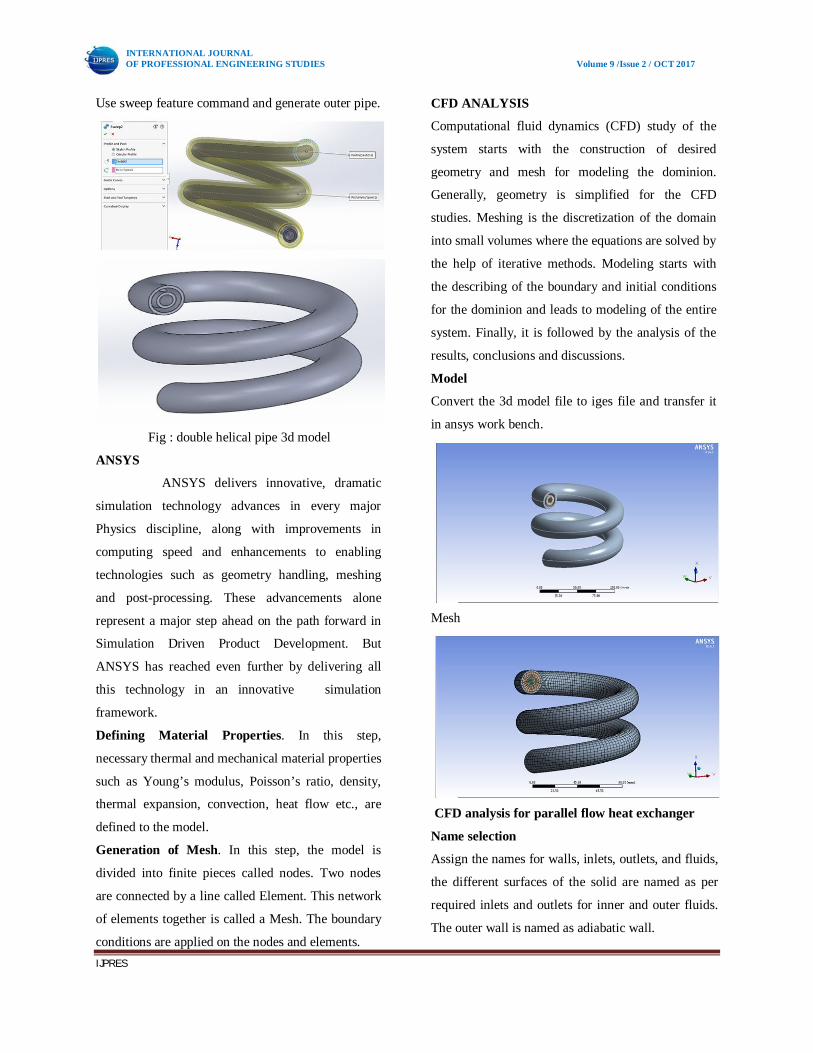
Use sweep feature command and generate outer pipe.
Fig : double helical pipe 3d model
ANSYS
ANSYS delivers innovative, dramatic
simulation technology advances in every major
Physics discipline, along with improvements in
computing speed and enhancements to enabling
technologies such as geometry handling, meshing
and post-processing. These advancements alone
represent a major step ahead on the path forward in
Simulation Driven Product Development. But
ANSYS has reached even further by delivering all
this technology in an innovative simulation
framework.
Defining Material Properties. In this step,
necessary thermal and mechanical material properties
such as Young’s modulus, Poisson’s ratio, density,
thermal expansion, convection, heat flow etc., are
defined to the model.
Generation of Mesh. In this step, the model is
divided into finite pieces called nodes. Two nodes
are connected by a line called Element. This network
of elements together is called a Mesh. The boundary
conditions are applied on the nodes and elements.
CFD ANALYSIS
Computational fluid dynamics (CFD) study of the
system starts with the construction of desired
geometry and mesh for modeling the dominion.
Generally, geometry is simplified for the CFD
studies. Meshing is the discretization of the domain
into small volumes where the equations are solved by
the help of iterative methods. Modeling starts with
the describing of the boundary and initial conditions
for the dominion and leads to modeling of the entire
system. Finally, it is followed by the analysis of the
results, conclusions and discussions.
Model
Convert the 3d model file to iges file and transfer it
in ansys work bench.
Mesh
CFD analysis for parallel flow heat exchanger
Name selection
Assign the names for walls, inlets, outlets, and fluids,
the different surfaces of the solid are named as per
required inlets and outlets for inner and outer fluids.
The outer wall is named as adiabatic wall.
Gurmeet
Typewritten Text
375

INTERNATIONAL JOURNAL OF PROFESSIONAL ENGINEERING STUDIES Volume 9 /Issue 2 / OCT 2017
IJPRES
Flow model
Viscous model
Select K-epsilon flow type
Cell zone condition
Select Fluid as water
Select solid inner & outer pipe as steel
Boundary conditions:
Cold Inlet velocity: 2 m/s
Hot inlet velocity: 1.8 m/s
Cold inlet temperature: 303 k
Hot inlet temperature: 353 k
Cold outlet: pressure outlet
Hot outlet: pressure outlet
Hot & cold fluid: water
Inner & outer Pipe material: steel
Adiabatic wall
Cold inlet
Momentum, velocity: 2 m/s
Thermal, Temperature: 303 k
Hot inlet:
Momentum, velocity: 1.8 m/s
Thermal, Temperature: 353 k
Outer pipe - Cold fluid
Temperature
Pressure
Gurmeet
Typewritten Text
376

INTERNATIONAL JOURNAL OF PROFESSIONAL ENGINEERING STUDIES Volume 9 /Issue 2 / OCT 2017
IJPRES
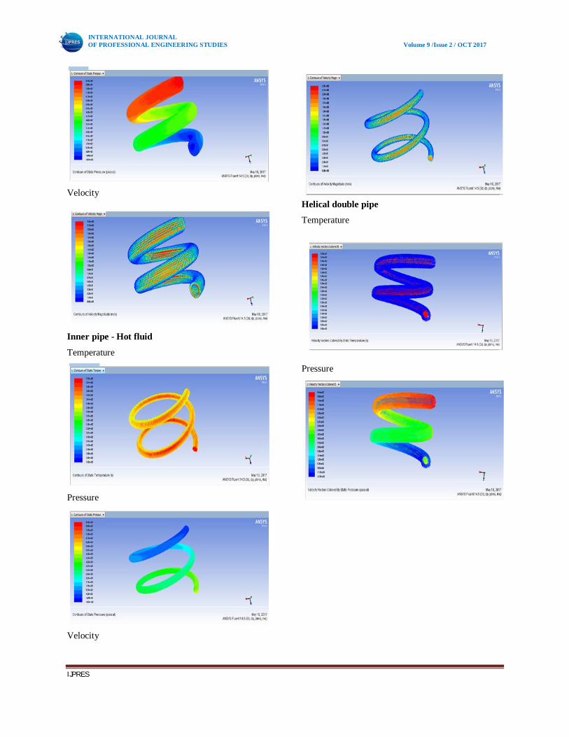
Velocity
Inner pipe - Hot fluid
Temperature
Velocity
Helical double pipe:
Temperature
Pressure
Velocity:
CFD Analysis for Counter Flow Heat Exchanger
Every step will be same as parallel flow heat
exchanger except name selection.
Boundary conditions will be same as parallel flow
heat exchanger.
Name selection
Assign the names for walls, inlets, outlets, and fluids,
the different surfaces of the solid are named as per
Gurmeet
Typewritten Text
377

INTERNATIONAL JOURNAL OF PROFESSIONAL ENGINEERING STUDIES Volume 9 /Issue 2 / OCT 2017
IJPRES
required inlets and outlets for inner and outer fluids
for counter flow heat exchanger. The outer wall is
named as adiabatic wall.
Outer pipe - Cold fluid
Temperature
Pressure
Gurmeet
Typewritten Text
378
INTERNATIONAL JOURNAL OF PROFESSIONAL ENGINEERING STUDIES Volume 9 /Issue 2 / OCT 2017
IJPRES
Velocity
Inner pipe - Hot fluid
Temperature
Pressure
Velocity
Helical double pipe
Temperature
Pressure
Gurmeet
Typewritten Text
379

INTERNATIONAL JOURNAL OF PROFESSIONAL ENGINEERING STUDIES Volume 9 /Issue 2 / OCT 2017
IJPRES
Velocity
Conclusions:
Modeling and analysis of helical double pipe
heat exchangers is done.
Modeling of helical double pipe heat
exchanger is done in solid works 2016
software using various commands.
Model is transfer to ansys 14.5 work bench
by converting it into iges file.
CFD analysis is carried out in Ansys fluent
for both parallel and counter flow of hot and
cold fluid.
Name selection is done as inlet, out let, fluid
solid, walls are assign and mesh the helical
double pipe heat exchanger.
Water is used as hot and cold fluid and steel
is used as material for both inner and outer
pipe
The boundary conditions are assign for
parallel and counter flow type heat
exchanger at inlet and outlet of pipes, outer
wall of outer cold pipe is made as adiabatic.
Temperatures, pressure and velocity of hot
and cold fluid at outlet are found out as
result of CFD analysis.
Temperature, pressure, velocity counters all
over the inner and outer pipe is shown.
Hence the study of temperature ,pressure
and velocity because of parallel and counter
flow in helical double pipe heat exchanger is
done in this project
References:
1. Experimental and CFD study of a single phase
cone-shaped helical coiled heat exchanger: an
empirical correlation. By Daniel Flórez-Orrego,
ECOSJune 26-29, 2012.
2. Helically Coiled Heat Exchangers by
J.S.Jayakumar.
3. Numerical And Experimental Studies of a
Double pipe Helical Heat Exchanger by Timothy
John Rennie, Dept. of Bio-resource Engg.
McGill University, Montreal August 2004.
4. Experimental and CFD estimation of heat transfer in helically coiled heat exchangers by J.S. Jayakumar, S.M. Mahajani, J.C. Mandal, P.K. Vijayan, and Rohidas Bhoi, 2008, Chemical Engg Research and Design 221-232. 5. Heat Transfer Optimization of Shell-and-Tube Heat Exchanger through CFD Studies by Usman Ur Rehman, 2011, Chalmers University of Technology. 6. Structural and Thermal Analysis of Heat Exchanger with Tubes of Elliptical Shape by Nawras H. Mostafa Qusay R. Al-Hagag, IASJ, 2012,Vol-8 Issue-3. 7. Numerical analysis of forced convection heat transfer through helical channels Dr. K. E. Reby Roy, IJEST, July-2012 vol-4. 8. Minton P.E., Designing Spiral Tube Heat Exchangers, Chemical Engineering, May 1970, p. 145. 9. Noble, M.A., Kamlani, J.S., and McKetta, J.J., Heat Transfer in Spiral Coils, Petroleum Engineer, April 1952, p. 723. 10. Heat Transfer Analysis of Helical Coil Heat Exchanger with Circular and Square Coiled Pattern by Ashok B. Korane, P.S. Purandare, K.V. Mali, IJESR, June 2012, vol-2, issue-6.
Gurmeet
Typewritten Text
380