CERTS Test Bed CERTEQUIP-V06-002, CERTS Static Switch, Low ... · Appendix F CERTS Switch Factory...
61
Arnold Schwarzenegger Governor CERTS MICROGRID LABORATORY TEST BED CERTS Test Bed CERTEQUIP-V06-002, CERTS Static Switch, Low Power Factory Acceptance Test Report Prepared For: California Energy Commission Public Interest Energy Research Program Prepared By: Lawrence Berkeley National Laboratory APPENDIX F
Transcript of CERTS Test Bed CERTEQUIP-V06-002, CERTS Static Switch, Low ... · Appendix F CERTS Switch Factory...
Arnold Schwarzenegger Governor
CERTS MICROGRID LABORATORY TEST BED
CERTS Test Bed CERTEQUIP-V06-002, CERTS Static Switch, Low Power
Factory Acceptance Test Report
Prepared For:
California Energy Commission Public Interest Energy Research Program
Prepared By: Lawrence Berkeley National Laboratory
AP
PE
ND
IX F

Prepared By: Lawrence Berkeley National Laboratory Joseph H. Eto, Principal Investigator Berkeley, CA 94720 Ed Linton and Hector Hurtado, Northern Power Systems Commission Contract No. 500-03-024
LBNL-802E
Prepared For: Public Interest Energy Research (PIER)
California Energy Commission
Bernard Treanton
Contract Manager
Mike Gravely
Program Area Lead
ENERGY SYSTEMS INTEGRATION Mike Gravely
Office Manager
ENERGY SYSTEMS RESEARCH
Martha Krebs, Ph.D.
PIER Director
Thom Kelly, Ph.D.
Deputy Director
ENERGY RESEARCH & DEVELOPMENT DIVISION
Melissa Jones
Executive Director
DISCLAIMER
This report was prepared as the result of work sponsored by the California Energy Commission. It does not necessarily represent the views of the Energy Commission, its employees or the State of California. The Energy Commission, the State of California, its employees, contractors and subcontractors make no warrant, express or implied, and assume no legal liability for the information in this report; nor does any party represent that the uses of this information will not infringe upon privately owned rights. This report has not been approved or disapproved by the California Energy Commission nor has the California Energy Commission passed upon the accuracy or adequacy of the information in this report.

Appendix F CERTS Switch Factory Acceptance Test REV.doc
Printed Copies are Uncontrolled
CERTS Test Bed
CERTEQUIP-V06-002
CERTS Switch
Low Power Factory Acceptance Test Report
Printed Copies are Uncontrolled
1
Contents
1 Introduction........................................................................................................................................................3
1.1 References ................................................................................................................................................3
1.2 Summary ...................................................................................................................................................3
2 S&C Power Electronic Switch and NPS DSP Controller Functionality........................................................5
2.1 S&C Power Electronic Switch ...................................................................................................................5
2.2 CERTS Switch Analog and Digital I/O ......................................................................................................6
2.3 CERTS Switch State Machine ..................................................................................................................6
2.4 CERTS Switch Operating Modes..............................................................................................................7
2.5 CERTS Switch System Control Functions ................................................................................................7
3 Test Results .......................................................................................................................................................9
3.1 S&C-DSP Interface Commissioning Test [Test Plan Section 2.1] ..........................................................10
3.1.1 S&C PES and DSP Controller I/O Interface .......................................................................................10
3.1.2 S&C PES Alarms ................................................................................................................................10
3.2 Synchronization [Test Plan Section 3.1] .................................................................................................12
3.2.1 Limits Accuracy (using Omicron CMA256-6 secondary injection test set from NREL) ......................12
3.2.2 Synchronization Time Delay (for Bias Closing) ..................................................................................13
3.2.3 Response to different beat frequencies ..............................................................................................16
3.3 Reverse Power and Anti-Islanding [Test Plan Section 3.3] ....................................................................20
3.3.1 Reverse Power (32) magnitude, time test ..........................................................................................20
3.3.2 Grid islanding and Open Phase [Test Plan Section 3.6] ....................................................................22
3.3.3 Anti-islanding, Microgrid Settings Reset (Lockout) .............................................................................25
3.4 IEEE 1547 Voltage and Frequency Tests...............................................................................................26
3.4.1 Over/Under Voltage tests [Test Plan Section 3.5] ..............................................................................26
3.4.2 Over/Under Frequency tests [Test Plan Section 3.4] .........................................................................28
3.5 SCR Switch Opening Time .....................................................................................................................30
3.6 SEL-351 Relay – DSP Controller Functionality [Test Plan Section 4] ....................................................31
3.6.1 SEL Relay TRIP output logic ..............................................................................................................32
3.6.2 SEL Relay minimum opening time and associated DSP reclosing ....................................................33
3.6.3 Relay to DSP delay.............................................................................................................................34
3.7 Dead Bus Reclosing [Test Plan Section 3.5.3] .......................................................................................35
3.7.1 DG Bus LO (27R) magnitude test .......................................................................................................36
3.7.2 DG Bus LO (27R) time test; “Dead Bus Reclose” operating mode ....................................................36
3.8 Restoration Timers ..................................................................................................................................37
3.9 Energy Manager System (EMS) .............................................................................................................40
3.10 CERTS Switch Full Functionality Test ....................................................................................................42
4 Appendix ..........................................................................................................................................................47
4.1 Appendix 1: IEEE1547 Tests Results with NREL’s Omicron Equipment (Section 3.3)..........................47
4.2 Appendix 2: List of DSP Controller settings in EMS (Section 3.9) ..........................................................54

Printed Copies are Uncontrolled
2
4.3 Appendix 3: Synchronization Tests (Section 3.2) plots...........................................................................56
Printed Copies are Uncontrolled
3
1 Introduction
1.1 References
� Reference 1: CERTEQUIP-T05-004, “CERTS Test Bed, Factory Acceptance Test, Static Switch Low Power Test Plan”
� Reference 2: CERTEQUIP-H03-002, “CERTS Static Switch Operation & Control”
� Reference 3: “Control and Design of CERTS Microgrid”, R. H. Lasseter and Paolo Piagi, Spetember 28,2005
� Reference 4: "Static Switch Test V2" (2/06), R.H. Lasseter
1.2 Summary
The CERTS Test Bed is designed to test advanced microgrid and distributed generation control concepts developed by Professor Robert Lasseter at the University of Wisconsin. It consists of inverter-coupled generators, loads, low-voltage distribution and data gathering equipment and a static switch to separate the microgrid from the utility. Separation allows the microgrid to operate as an island, protecting its loads when there is a problem with the utility supply. The switch implements IEEE-1547 DG interface requirements, protecting the utility from reverse power and the microgrid from utility power quality issues. Disconnection and reconnection are accomplished smoothly with reduced transients presented to either side.
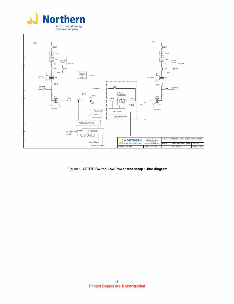
The switch chosen for the Test Bed was supplied by S&C Electric. It is a 480V, 400A thyristor (SCR) switch with controller, a modified Pure-Wave UPS product without the inverter and battery. To implement the required CERTS function we have added Northern Power’s DSP controller and a programmable SEL-351 protective relay. This assembly was tested at reduced power in our lab. A one-line schematic of the test set up is given in Figure 1 below.
We used an existing inverter development test bed to provide controllable Microgrid and utility sources. The utility side inverter was operated as a voltage source with the ability to control voltage and frequency. The microgrid inverter used the University of Wisconsin control method with power / frequency droop. Control code for this method had been developed under an earlier phase of this CERTS contract. Each inverter was capable of 15 kVA output and included controllable load banks.
The test plan is given in Reference1, test results are detailed in this report. Some revisions were made during testing to meet the capacities of the source inverters and to follow up on discovered issues. S&C provided an applications engineer, Rodger Troyer, for three days on site to rectifying problems found during the initial test runs. Also during testing it was decided to add measurements made by NREL using their Omicron test equipment, applying secondary signal injection to test the IEEE1547 voltage and frequency functions of the DSP Controller. Those measurements, made by Chris Pink of NREL, are included in this report. A final round of static switch testing (Power Quality CBEMA and SEMIF47 events) is planned for the Dolan Labs at AEP before the switch is installed at AEP in the CERTS Test Bed.
Printed Copies are Uncontrolled
4
Drawn by: Date: Sheet of
CERTS Test Bed - Static Switch & DPS Control
Ed Linton 02/07/2005 2 2
Rev. BPROJ#:
AB
CD
EF
G
182 Mad River Park
Waitsfield, VT 05673
802-496-2955
www.northernpower.com
file: Drawing3
CB14
PT14
CT14
CT12CB12
CB17
TransientSuppression
CB16
Relay 2
Analog Input Board
TI 2407 DSP
S&C Control
Modbus port to EMS
Engr. HMI port
3
33
3
PT17
Feeder C
Load Bank
R3
20 kW
Low Power Test Fixture
CB13
Cabinet 2a
Utility
CB4R
CB4
XF3
DG Load
R4 20kW
FS4
208V
480V
PR4
Rect 4
CB4L
CB5R
CB5
XF4
Grid Load
R1 20kW
CB4PRG
FS5
208V
PR5
Rect 5
CB5L
3,5,12 kW3,5,12 kW
PES
Open/Close Command
Remote Reset
PES Ready to Close
PES StatusPES Fault
CB4G
208 Y/480 D
480 D/480 Y
XFL1
480 D/480 Y
XFL2
CB3PRG
CB3G
208 Y/480 D
3,5,12 kW
4
3
4
3
275151N
27 59 25 3281
O/U
Figure 1. CERTS Switch Low Power test setup 1-line diagram
Printed Copies are Uncontrolled
5
2 S&C Power Electronic Switch and NPS DSP Controller Functionality
This section is intended to provide a brief description of the control functions that the Northern Power DSP Controller will perform, as well as a description of the interface between the S&C SCR switch control and the DSP Controller. For a complete description of this functionality and Interface, refer to Reference [2].
2.1 S&C Power Electronic Switch
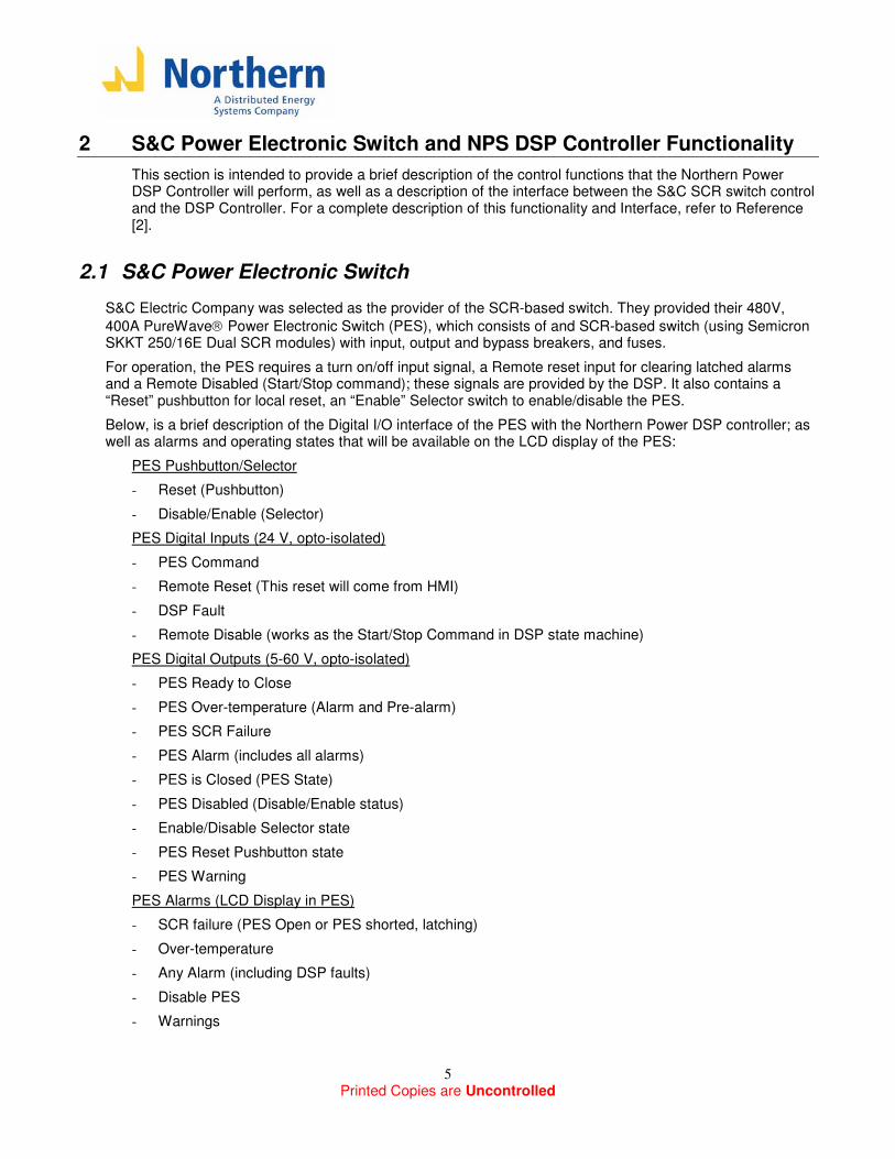
S&C Electric Company was selected as the provider of the SCR-based switch. They provided their 480V,
400A PureWave Power Electronic Switch (PES), which consists of and SCR-based switch (using Semicron SKKT 250/16E Dual SCR modules) with input, output and bypass breakers, and fuses.
For operation, the PES requires a turn on/off input signal, a Remote reset input for clearing latched alarms and a Remote Disabled (Start/Stop command); these signals are provided by the DSP. It also contains a “Reset” pushbutton for local reset, an “Enable” Selector switch to enable/disable the PES.
Below, is a brief description of the Digital I/O interface of the PES with the Northern Power DSP controller; as well as alarms and operating states that will be available on the LCD display of the PES:
PES Pushbutton/Selector
- Reset (Pushbutton)
- Disable/Enable (Selector)
PES Digital Inputs (24 V, opto-isolated)
- PES Command
- Remote Reset (This reset will come from HMI)
- DSP Fault
- Remote Disable (works as the Start/Stop Command in DSP state machine)
PES Digital Outputs (5-60 V, opto-isolated)
- PES Ready to Close
- PES Over-temperature (Alarm and Pre-alarm)
- PES SCR Failure
- PES Alarm (includes all alarms)
- PES is Closed (PES State)
- PES Disabled (Disable/Enable status)
- Enable/Disable Selector state
- PES Reset Pushbutton state
- PES Warning
PES Alarms (LCD Display in PES)
- SCR failure (PES Open or PES shorted, latching)
- Over-temperature
- Any Alarm (including DSP faults)
- Disable PES
- Warnings
Printed Copies are Uncontrolled
6
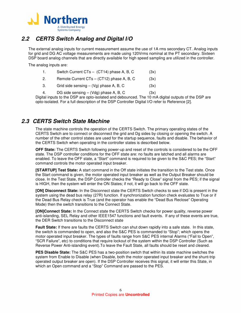
2.2 CERTS Switch Analog and Digital I/O
The external analog inputs for current measurement assume the use of 1A rms secondary CT. Analog inputs for grid and DG AC voltage measurements are made using 120Vrms nominal at the PT secondary. Sixteen DSP board analog channels that are directly available for high speed sampling are utilized in the controller.
The analog inputs are:
1. Switch Current CTs – (CT14) phase A, B, C (3x)
2. Remote Current CTs – (CT12) phase A, B, C (3x)
3. Grid side sensing – (Vg) phase A, B, C (3x)
4. DG side sensing – (Vdg) phase A, B, C (3x) Digital inputs to the DSP are opto-isolated and debounced. The 10 mA digital outputs of the DSP are opto-isolated. For a full description of the DSP Controller Digital I/O refer to Reference [2].
2.3 CERTS Switch State Machine
The state machine controls the operation of the CERTS Switch. The primary operating states of the CERTS Switch are to connect or disconnect the grid and Dg sides by closing or opening the switch. A number of the other control states are used for the startup sequence, faults and disable. The behavior of the CERTS Switch when operating in the controller states is described below.
OFF State: The CERTS Switch following power-up and reset of the controls is considered to be the OFF state. The DSP controller conditions for the OFF state are: no faults are latched and all alarms are enabled. To leave the OFF state, a “Start” command is required to be given to the S&C PES; the “Start” command controls the motor operated input breaker.
[STARTUP] Test State: A start command in the Off state initiates the transition to the Test state. Once the Start command is given, the motor operated input breaker as well as the Output Breaker should be close. In the Test State, the DSP Controller checks the “Ready to Close” signal from the PES; if the signal is HIGH, then the system will enter the ON States; if not, it will go back to the OFF state.
[ON] Disconnect State: In the Disconnect state the CERTS Switch checks to see if DG is present in the system using the dead bus relay (27R) function. If synchronization function check evaluates to True or if the Dead Bus Relay check is True (and the operator has enable the “Dead Bus Reclose” Operating Mode) then the switch transitions to the Connect State.
[ON]Connect State: In the Connect state the CERTS Switch checks for power quality, reverse power anti-islanding, SEL Relay and other IEEE1547 functions and fault events. If any of these events are true, the DER Switch transitions to the Disconnect state
Fault State: If there are faults the CERTS Switch can shut down rapidly into a safe state. In this state, the switch is commanded to open, and also the S&C PES is commanded to “Stop”; which opens the motor operated input breaker. The types of faults range from S&C PES internal Alarms (“Fail to Open”, “SCR Failure”, etc) to conditions that require lockout of the system within the DSP Controller (Such as Reverse Power Anti-islanding event).To leave the Fault State, all faults should be reset and cleared.
PES Disable State: The S&C PES has a two-position switch that within its state machine switches the system from Enable to Disable (when Disable, both the motor operated input breaker and the shunt-trip operated output breaker are open). If the DSP Controller receives this signal, it will enter this State, in which an Open command and a “Stop” Command are passed to the PES.
Printed Copies are Uncontrolled
7
2.4 CERTS Switch Operating Modes
Auto mode: In this mode, when conditions are appropriate synchronized closing of the switch is attempted; also all events are checked.
Manual Connection Mode: In this mode, the switch can be manually controlled to open or close. Also, during this mode, events are not checked (Except for the “External Relay Trip” event, which in any mode will always open the SCR switch).
Sync Test Bypass: If manual connection mode is enabled, it will try to attempt to close when synchronization conditions are appropriate. However, if the Sync Test Bypass option is also enabled at the same time, then it will skip the synchronization test and force a switch close regardless of the grid and DG conditions.
EFVST (Enable Fast Voltage Sag Trip) Mode: If this operating mode is enable, during “Auto” Mode, Power Quality (CBEMA,SEMIF47) events and trips will be enabled. If disabled, the switch will not be commanded to open is these events occur. This mode can be disabled manually through the EMS; also the EMS may disabled it automatically based on wether there is enough microsources available to cover the microgrid load.
Dead Bus Reclose: If this operating mode is enable, when running in “Auto” Mode, reclosing to a DG side dead bus is allowed in order to perform system black starts. Notice that the operating mode simply allows or blocks the dead bus reclosing; the detection of the dead bus is perform by the relay function “Dead Bus Reclose Relay” described in section 2.5
2.5 CERTS Switch System Control Functions
Several protection, IEE1547, Power Quality and control functions are performed by the CERTS switch; they are listed below:
Synchronism Check: The calculation of this algorithm is performed in the Disconnect state. This function checks to verify that the voltage amplitude (for all three phases), frequency and phase angle are within an acceptable window to enable the closing of the DER Switch. Note that other CERTS Switch control functions may also need to be true to enable the closing.
The voltage magnitude and phase comparison is performed at the high speed ISR rate of the DSP. This ensures that any sudden jump in voltage or magnitude on either side of the CERTS Switch does not cause any false synchronization.
IEEE 1547 Voltage and Frequency Events: The recently approved IEEE 1547 standard contains requirements under certain voltage and frequency events. The levels on these events are fully described in section 3.3.3. If any of these events occur when operating in the “Auto” Mode, the switch will transition from the Connect to the Disconnect State, and if it is already in the Disconnect State, it will prevent the switch from closing.
Relay Trip Signal Event: The SEL-351 Relay (Relay 2) associated with the CERTS Switch will perform protection functions that include phase overcurrent, zero sequence overcurrent and line to line undervoltage. When the Relay detects these conditions, it will provide a trip signal to the CERTS controller so it can command the switch to open.
Dead Bus Reclose Relay: This relay function is provided in the CERTS Switch, so that black start of loads is allowed when there are no microsources present on the DG side.
Phase Sequence Error: This function checks for phase rotation direction, missing phase information or lack of signal on the phase voltage. In addition this function checks if the controller’s internal data is

Printed Copies are Uncontrolled
8
synchronized with the grid and DG operating frequencies. This event in the Connect state will make the CERTS Switch to transition to Disconnect state. An event in the Disconnect state will prevent the operation of synchronization function.
Remote Location RMS Reverse Power (32) and Anti-islanding: The CERTS controller evaluates single and three phase power flow at the remote Current transformer (CT12) location, which is located at the PCC (so its measurement includes protected and unprotected loads of the microgrid). The power measurement is compared with an adjustable threshold and time delay for coordination. If the power flow crosses the threshold then an event is set. An event in the Connect state will cause the CERTS Switch to transition to the Disconnect state. Depending on the state of the grid voltage after transitioning to the Disconnect state (which allows the Controller to decide wether the reverse power event was caused due to grid islanding, open phase or Erroneous Microgrid settings), the Switch may be allowed to reclose when conditions are appropriate (grid islanding, open phase) or the system will enter the fault state and require user intervention (Anti-islanding, Microgrid Settings Reset required).
Controller Digital Event: In addition to the above, functions it is possible to set a bit in the CERTS Switch controller to simulate an event. Also it is possible to use the external digital input to simulate an event occurrence in the controller.
Restoration Timers: IEEE 1547 and Power Quality events will have restoration timers, meaning that once the measured parameters (voltage and frequency) return to normal levels, they should stayed within acceptable limits for at least the time specified in these timers. Two separate timers will exist: one for IEEE 1547 events, which will be a longer time (default 5 minutes) while Power Quality Events will have a faster separate timer (2 seconds). Both timers will be adjustable.
Printed Copies are Uncontrolled
9
3 Test Results
This section presents the results of all the tests performed at the Northern Power test facility Below are given some aspects of the general procedure taken in order to perform the low-power test for the CERTS switch. Specific settings for the testing of each kind of event and algorithm are specified in each subsection; notice that some settings used may differ from the original settings in the test plan due to limitations of the source inverters used. The changes are not significant, the intent of the test plan has been maintained.
Figure 1 shows a 1-line diagram of the test setup used for the low-power testing.
Notes about the general test procedure:
1. The CERTS Switch unit was connected to the source inverters and loads, with one inverter and load pair emulating the grid and another pair emulating the DG source. The Grid source operates in open loop mode (Constant voltage magnitude and frequency) while the DG source operates using CERTS microgrid controls (Reference [3]).
2. During the testing of the different types of algorithms, only the event functions under test were enabled, while all other event functions were disabled. The event settings were adjusted to the appropriate values related to the test objective.
3. During the testing of most algorithms and events, the Northern Power Engineering HMI was used as the interface between the user and the DSP. Through this display the operator was able to observe the status of all alarms and events as well as the status of the switch (information from the S&C PES); also the operator was able to adjust any settings on the fly. In section (“EMS testing”) most of these tests are repeated but using the Energy Manager System that will be available at AEP in order to verify required communications.
Printed Copies are Uncontrolled
10
3.1 S&C-DSP Interface Commissioning Test [Test Plan Section 2.1]
3.1.1 S&C PES and DSP Controller I/O Interface
The first sets of tests performed are to verify that basic functionality, wiring and interface between the S&C switch and the DSP Controller were working properly. The following steps were performed, and all of them passed successfully.
- Wiring Check: All wiring was verified for proper connection according to schematics, as well as check for mechanical and electrical integrity (DSP Controller only)
- Power Supply: 24V power supply for DSP Controller and Relay2 was checked successfully.
- Digital Inputs and Outputs: Correct operation and logic polarity of all inputs and outputs was verified by simulating several kind of events.
- State Machine: We loop through the state machine as detailed in section 2 of this report several times, and both the S&C and DSP operate as expected. All desired status are communicated between the S&C and the controller
- Alarms: Some of the S&C Alarms were tested; results are detailed in section 3.1.2
- Analog Inputs: All analog inputs (voltage, current) were checked for correct scaling and response. Some calibration was performed to achieve the following accuracies:
Voltage: < 1% error (2.7 Vrms, measured at rated voltage 277Vrms)
Current < 2 Arms error (maximum current simulated = 20 Arms, switch rating = 400A)
Power error < 1 kW (maximum power simulated = 15 kW, switch rating is 330 kVA)
3.1.2 S&C PES Alarms
Some additional simple tests were attempted in order to verify the functionality of the S&C Internal Alarms. A detail description of each of these alarms can be seen in Reference [2]. The status of these alarms is communicated to the DSP controller by the following digital outputs:
PES Alarm: This output includes toggles HIGH if any of the S&C alarms in enabled (Over temperature, Open PES, Shorted PES, PES Fail to Open) SCR Failure: This output toggles HIGH if either the Open PES or Shorted PES alarms is enabled
3.1.2.1 Fail to Open Alarm
A strategy was devised to test the operation of this alarm. The grid side inverter was set to operate in open loop mode (constant voltage, frequency) while the DG side had only a passive load (5 kW). Also, a single phase contactor across phase A of the SCR switch was connected, but initially left open.
After performing a Manual Connect of the SCR switch with the DSP controller, the single phase contactor was closed. Then, the Manual Connect command was removed; even though the SCR switch opens, the S&C controls will not measure any voltage buildup across the SCR phase A (since the single phase contactor is shorting the connection); thus assuming that the SCR switch has failed to open. When this occurs, the “PES Alarm” digital output goes HIGH, and after the DSP receives this signal, it transfers the CERTS switch to the Fault State and gives a “Stop” command to the S&C PES.
Printed Copies are Uncontrolled
11
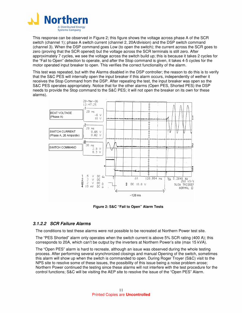
This response can be observed in Figure 2; this figure shows the voltage across phase A of the SCR switch (channel 1); phase A switch current (channel 2, 20A/division) and the DSP switch command (channel 3). When the DSP command goes Low (to open the switch); the current across the SCR goes to zero (proving that the SCR opened) but the voltage across the SCR terminals is still zero. After approximately 7 cycles, we see the voltage across the switch build up; this is because it takes 2 cycles for the “Fail to Open” detection to operate, and after the Stop command is given, it takes 4-5 cycles for the motor operated input breaker to open. This verifies the correct functionality of the alarm.
This test was repeated, but with the Alarms disabled in the DSP controller; the reason to do this is to verify that the S&C PES will internally open the input breaker if this alarm occurs, independently of wether it receives the Stop Command from the DSP. After repeating the test, the input breaker was open so the S&C PES operates appropriately. Notice that for the other alarms (Open PES, Shorted PES) the DSP needs to provide the Stop command to the S&C PES; it will not open the breaker on its own for these alarms).
Figure 2: S&C “Fail to Open” Alarm Tests
3.1.2.2 SCR Failure Alarms
The conditions to test these alarms were not possible to be recreated at Northern Power test site.
The “PES Shorted” alarm only operates when the switch current is above 5% SCR rating (400 A); this corresponds to 20A, which can’t be output by the inverters at Northern Power’s site (max 15 kVA).
The “Open PES” alarm is hard to recreate, although an issue was observed during the whole testing process. After performing several srynchronized closings and manual Opening of the switch, sometimes this alarm will show up when the switch is commanded to open. During Roger Troyer (S&C) visit to the NPS site to resolve some of these issues, the possibility of this issue being a noise problem arose; Northern Power continued the testing since these alarms will not interfere with the test procedure for the control functions; S&C will be visiting the AEP site to resolve the issue of the “Open PES” Alarm.
Printed Copies are Uncontrolled
12
3.2 Synchronization [Test Plan Section 3.1]
The synchronization tests were intended to demonstrate that the CERTS Switch would permit connection between the grid and DG terminals when both systems are synchronized within an allowable window for voltage, frequency and phase.
The following tests were performed to verify the synchronization functionality:
1) Limits Accuracy (using Omicron CMA256-6 secondary injection test set from NREL)
2) Synchronization Time Delay (for Bias Closing)
3) Response to different beat frequencies
3.2.1 Limits Accuracy (using Omicron CMA256-6 secondary injection test set from NREL)
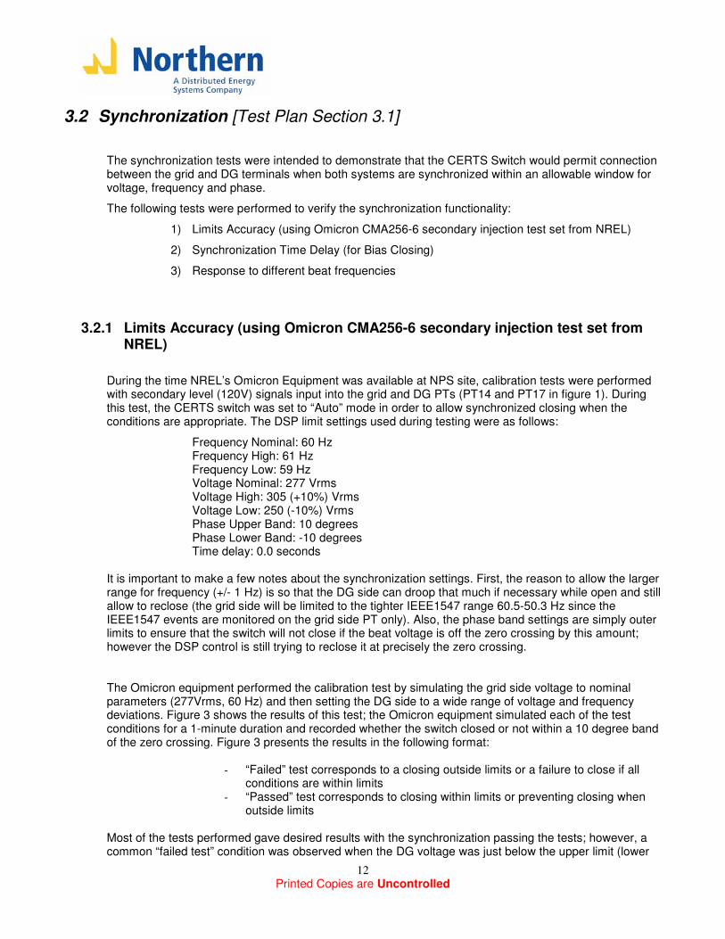
During the time NREL’s Omicron Equipment was available at NPS site, calibration tests were performed with secondary level (120V) signals input into the grid and DG PTs (PT14 and PT17 in figure 1). During this test, the CERTS switch was set to “Auto” mode in order to allow synchronized closing when the conditions are appropriate. The DSP limit settings used during testing were as follows:
Frequency Nominal: 60 Hz Frequency High: 61 Hz Frequency Low: 59 Hz Voltage Nominal: 277 Vrms Voltage High: 305 (+10%) Vrms Voltage Low: 250 (-10%) Vrms Phase Upper Band: 10 degrees Phase Lower Band: -10 degrees Time delay: 0.0 seconds
It is important to make a few notes about the synchronization settings. First, the reason to allow the larger range for frequency (+/- 1 Hz) is so that the DG side can droop that much if necessary while open and still allow to reclose (the grid side will be limited to the tighter IEEE1547 range 60.5-50.3 Hz since the IEEE1547 events are monitored on the grid side PT only). Also, the phase band settings are simply outer limits to ensure that the switch will not close if the beat voltage is off the zero crossing by this amount; however the DSP control is still trying to reclose it at precisely the zero crossing. The Omicron equipment performed the calibration test by simulating the grid side voltage to nominal parameters (277Vrms, 60 Hz) and then setting the DG side to a wide range of voltage and frequency deviations. Figure 3 shows the results of this test; the Omicron equipment simulated each of the test conditions for a 1-minute duration and recorded whether the switch closed or not within a 10 degree band of the zero crossing. Figure 3 presents the results in the following format:
- “Failed” test corresponds to a closing outside limits or a failure to close if all conditions are within limits
- “Passed” test corresponds to closing within limits or preventing closing when outside limits
Most of the tests performed gave desired results with the synchronization passing the tests; however, a common “failed test” condition was observed when the DG voltage was just below the upper limit (lower
Printed Copies are Uncontrolled
13
by 2.7 Vrms (1%)). Is possible that there is a calibration issue with the DG voltage measurements at this level; however, 1% is a relatively acceptable accuracy.
CERTS DSP Synchronization Tests
Grid Nominal Parameters: 277V, 60 Hz
-35
-30
-25
-20
-15
-10
-5
0
5
10
15
20
25
30
35
-1.2 -1 -0.8 -0.6 -0.4 -0.2 0 0.2 0.4 0.6 0.8 1 1.2
DG DeltaF (Hz)
DG
De
ltaV
(V
)
Failed Test
Passed Test
Limits
Figure 3: DSP Synchronization Limits Accuracy Test using NREL’s Omicron Equipment
3.2.2 Synchronization Time Delay (for Bias Closing)
One of the settings available in Northern Power’s DSP Controller is a “time delay” for synchronization closing. The initial purpose of this time delay is to compensate for opening time of devices such as circuit breakers (which typically can take up to 5 cycles to open). However, for the CERTS switch project this time delay can also be used to test the concept of biasing the closing such that switch closes when the fastest rotating voltage must be leading the voltage that rotates slower (check Reference [3]). Without the bias, the controller will try to close when both voltages are on phase (meaning the average phase of the three beat voltages A, B, C is zero). The bias closing can be achieved by using a positive time delay; a negative time delay will perform the opposite effect (switch closes when the fastest rotating voltage is lagging the voltage that rotates slower). In this situation, the initial direction of power flow will be opposite to the expected steady state power flow direction, thus creating a significant transient response. Also notice that the setting in the Engineering HMI is a time value (in seconds); the equivalent phase bias is obtained by multiplying the beat frequency of the voltage across the switch and this time delay value. To examine the effect of the bias closing, the following setup was used: Grid Side:

Printed Copies are Uncontrolled
14
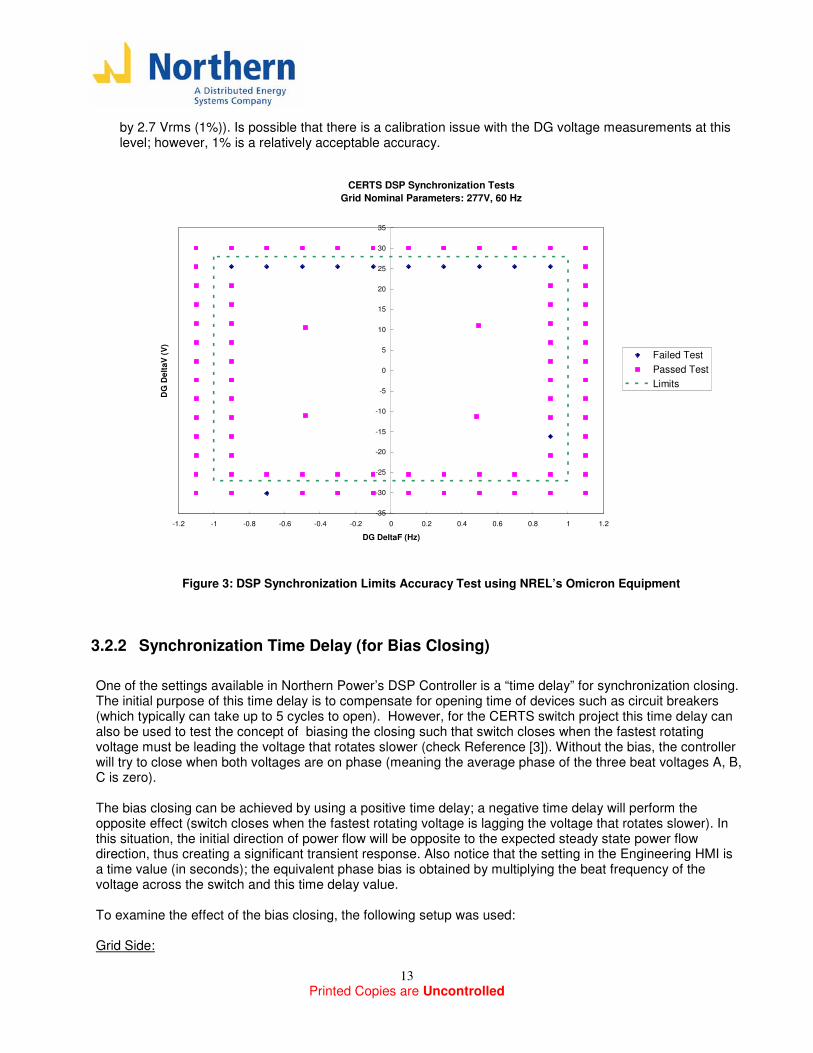
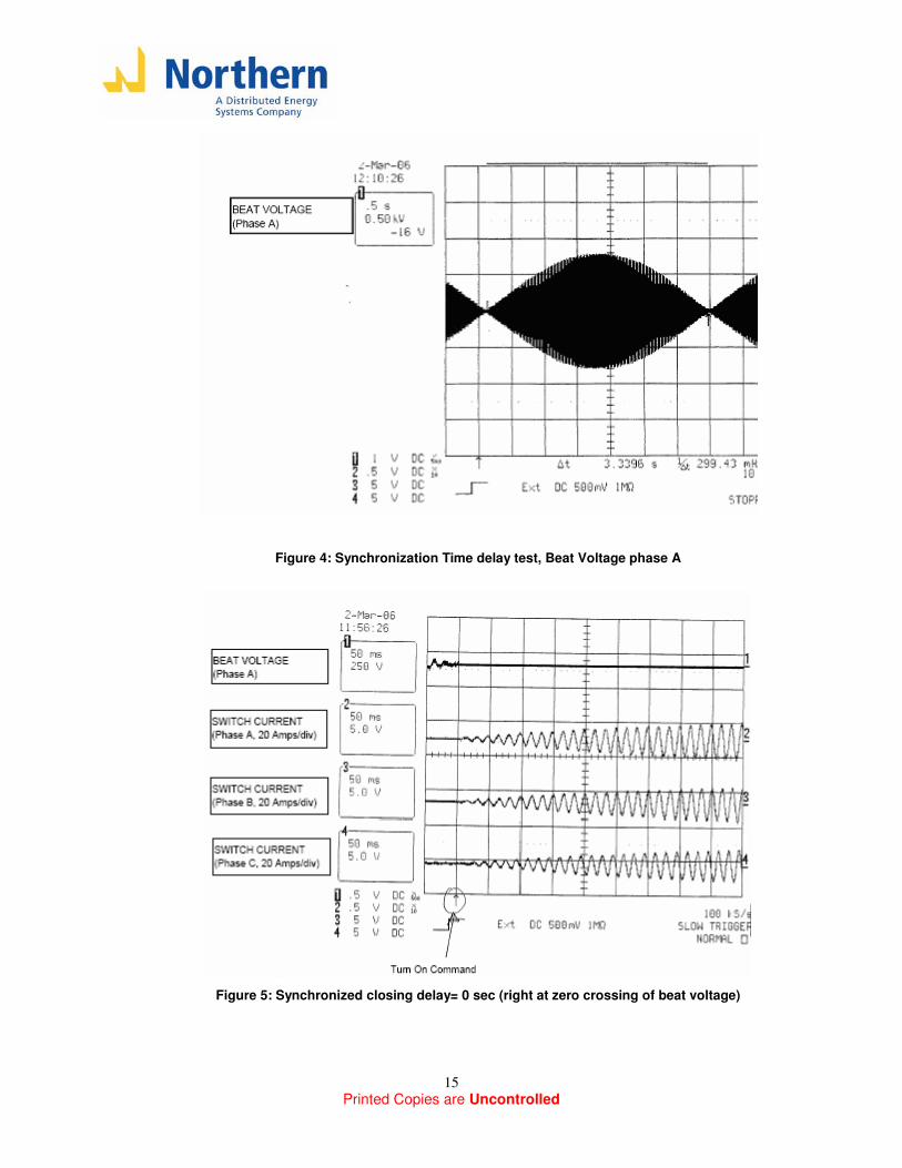
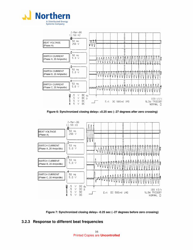
Voltage: 277Vrms Frequency: 60 Hz Grid Load (R1), Feeder C Load (R3) = 0 kW DG side: Psetpoint= 6 kW Dg Load (R4) = 12 kW Droop: 0.025 Hz/kW Frequency Measured (before closing): 59.7 Hz This setup allows us to test an scenario with a beat frequency of 0.3 Hz. When the switch closes, a power flow from the grid side to the DG side of approximately 6 kW results. The following waveforms were recorded: - Figure 4: Beat Voltage - Figure 5: Synchronized closing delay= 0 sec (right at zero crossing of beat voltage) - Figure 6: Synchronized closing delay= +0.25 sec (~27 degrees after zero crossing) - Figure 7: Synchronized closing delay= -0.25 sec (~27 degrees after zero crossing) Figures 5-7 show the following measurements:
- Channel 1: Voltage across the switch phase A (Beat Voltage) - Channel 2: Phase A switch current (20A/division) - Channel 3: Phase B switch current (20A/division) - Channel 4: Phase C switch current (20A/division)
Also, the time axis shows an arrow (trigger) which is where the Switch command (open/close) transition from open to close. These figures show that with a zero delay, the closing transition was very smooth and the current is slowly growing to its steady state value. Also, with the positive time delay, the current is biased in the correct power flow direction, so the transition is also relatively smooth. However, with the negative time delay, we can see that the current in all the phases takes initially the wrong direction, so an unwanted transient is observed. This shows that it is desired to avoid closing of the switch when the fastest voltage is lagging the slower voltage. Since is shown that the DSP can measure phase very accurately, from here on it is expected that synchronized closing will be performed without any bias (time delay). This setting will be available if desired to test on the field for certain conditions where the phase measurement by the DSP may not be as accurate (harmonic content, significant phase unbalance) and thus the bias could smooth out the transitions. An important observation to note during this test is that with no delay, we see the switch current is slowly growing to its steady state and taking 8-10 cycles to reach that point. The reason for this behavior is that what we call the Grid side is not really a stiff voltage source because of the impedance of the two transformers (total X~10% at 15kVA, 480V). If this was a stiff source, the current should take ~1 cycle to reach its steady state when closing at exactly the zero crossing; this kind of response will be observed in future synchronization tests, and as explained here it is very probable it occurs due to impedance of the grid connection in the test setup.
Printed Copies are Uncontrolled
15
Figure 4: Synchronization Time delay test, Beat Voltage phase A
Figure 5: Synchronized closing delay= 0 sec (right at zero crossing of beat voltage)
Printed Copies are Uncontrolled
16
Figure 6: Synchronized closing delay= +0.25 sec (~27 degrees after zero crossing)
Figure 7: Synchronized closing delay= -0.25 sec (~27 degrees before zero crossing)
3.2.3 Response to different beat frequencies
Printed Copies are Uncontrolled
17
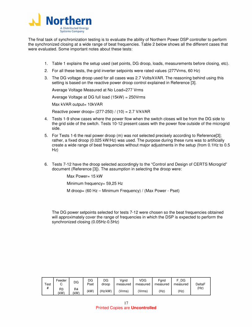
The final task of synchronization testing is to evaluate the ability of Northern Power DSP controller to perform the synchronized closing at a wide range of beat frequencies. Table 2 below shows all the different cases that were evaluated. Some important notes about these tests:
1. Table 1 explains the setup used (set points, DG droop, loads, measurements before closing, etc).
2. For all these tests, the grid inverter setpoints were rated values (277Vrms, 60 Hz)
3. The DG voltage droop used for all cases was 2.7 Volts/kVAR. The reasoning behind using this setting is based on the reactive power droop control explained in Reference [3].
Average Voltage Measured at No Load=277 Vrms
Average Voltage at DG full load (15kW) = 250Vrms
Max kVAR output= 10kVAR
Reactive power droop= (277-250) / (10) = 2.7 V/kVAR
4. Tests 1-9 show cases where the power flow when the switch closes will be from the DG side to the grid side of the switch. Tests 10-12 present cases with the power flow outside of the microgrid side.
5. For Tests 1-6 the real power droop (m) was not selected precisely according to Reference[3]; rather, a fixed droop (0.025 kW/Hz) was used. The purpose during these runs was to artificially create a wide range of beat frequencies without major adjustments in the setup (from 0.1Hz to 0.5 Hz)
6. Tests 7-12 have the droop selected accordingly to the “Control and Design of CERTS Microgrid” document (Reference [3]). The assumption in selecting the droop were:
Max Power= 15 kW
Minimum frequency= 59,25 Hz
M droop= (60 Hz – Minimum Frequency) / (Max Power - Pset)
The DG power setpoints selected for tests 7-12 were chosen so the beat frequencies obtained will approximately cover the range of frequencies in which the DSP is expected to perform the synchronized closing (0.05Hz-0.5Hz)
Feeder C
DG DG Pset
DG droop
Vgrid measured
VDG measured
Fgrid measured
F_DG measured Test
# R3 (kW)
R4 (kW)
(kW) (Hz/kW) (Vrms) (Vrms) (Hz) (Hz)
DeltaF (Hz)
Printed Copies are Uncontrolled
18
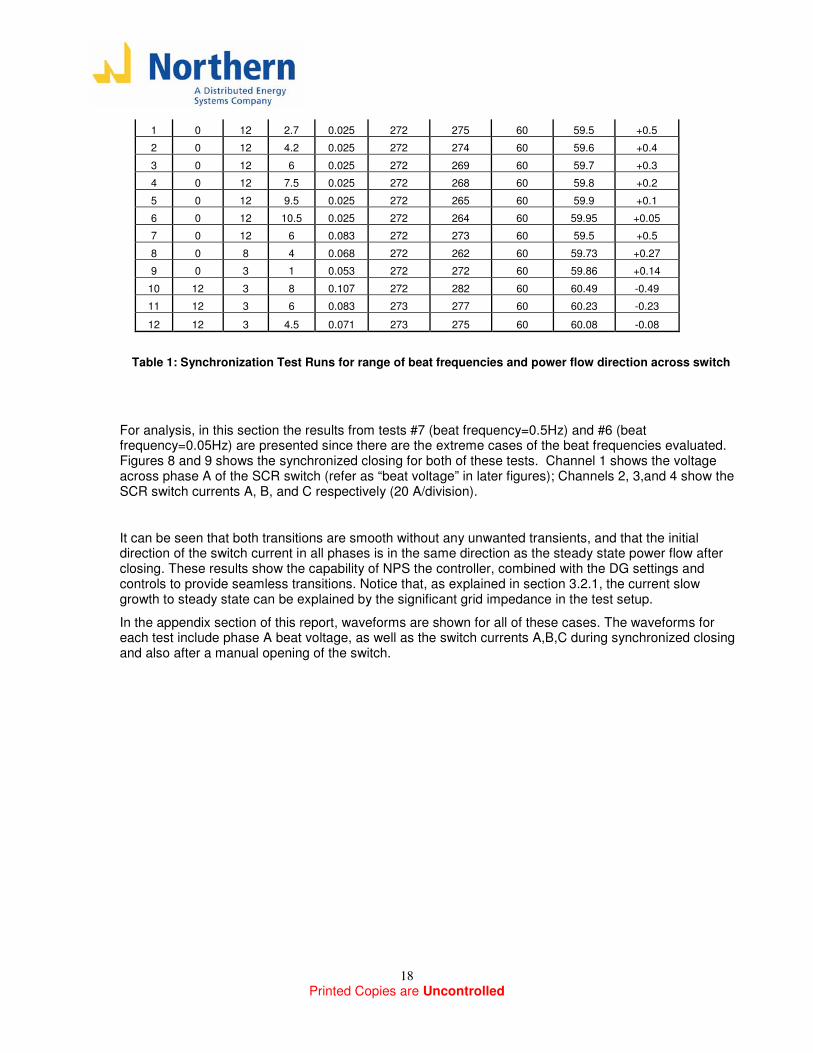
1 0 12 2.7 0.025 272 275 60 59.5 +0.5
2 0 12 4.2 0.025 272 274 60 59.6 +0.4
3 0 12 6 0.025 272 269 60 59.7 +0.3
4 0 12 7.5 0.025 272 268 60 59.8 +0.2
5 0 12 9.5 0.025 272 265 60 59.9 +0.1
6 0 12 10.5 0.025 272 264 60 59.95 +0.05
7 0 12 6 0.083 272 273 60 59.5 +0.5
8 0 8 4 0.068 272 262 60 59.73 +0.27
9 0 3 1 0.053 272 272 60 59.86 +0.14
10 12 3 8 0.107 272 282 60 60.49 -0.49
11 12 3 6 0.083 273 277 60 60.23 -0.23
12 12 3 4.5 0.071 273 275 60 60.08 -0.08
Table 1: Synchronization Test Runs for range of beat frequencies and power flow direction across switch
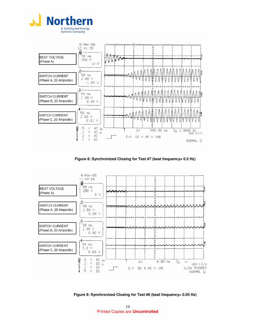
For analysis, in this section the results from tests #7 (beat frequency=0.5Hz) and #6 (beat frequency=0.05Hz) are presented since there are the extreme cases of the beat frequencies evaluated. Figures 8 and 9 shows the synchronized closing for both of these tests. Channel 1 shows the voltage across phase A of the SCR switch (refer as “beat voltage” in later figures); Channels 2, 3,and 4 show the SCR switch currents A, B, and C respectively (20 A/division).
It can be seen that both transitions are smooth without any unwanted transients, and that the initial direction of the switch current in all phases is in the same direction as the steady state power flow after closing. These results show the capability of NPS the controller, combined with the DG settings and controls to provide seamless transitions. Notice that, as explained in section 3.2.1, the current slow growth to steady state can be explained by the significant grid impedance in the test setup.
In the appendix section of this report, waveforms are shown for all of these cases. The waveforms for each test include phase A beat voltage, as well as the switch currents A,B,C during synchronized closing and also after a manual opening of the switch.
Printed Copies are Uncontrolled
19
Figure 8: Synchronized Closing for Test #7 (beat frequency= 0.5 Hz)
Figure 9: Synchronized Closing for Test #6 (beat frequency= 0.05 Hz)
Printed Copies are Uncontrolled
20
3.3 Reverse Power and Anti-Islanding [Test Plan Section 3.3]
In this section, the reverse power algorithm as well as the functionalities that it is part of will be tested. The reverse power algorithm event will be running when operating in the “Auto” Mode, and if the conditions of the power flow make this event true, then the DSP will command the switch to open. Additionally, based on the kind of condition that causes the reverse power event, the DSP will take a decision wether to reclose the switch when conditions are appropriate, or simply lockout the system. This decision will be based on what the grid side voltage is after the switch has opened after a reverse power event:
• If after the switch opens on a reverse power event, any of phases of the grid voltage is low (due to a grid upstream islanding or due to an open phase) then, once conditions are normal for synchronization and all events are cleared, the DSP will try to reclose the switch.
• If after the switch opens on a reverse power event, all phases of the grid voltage is normal, then it means that the reverse power condition was created due to incorrect power setpoints in the DG sources (DG Pset > microgrid load); in this situation, then the DSP should create a fault that will be displayed to the user though the Engineering HMI or EMS as “Reverse Power Anti-islanding = Microgrid Settings Reset” and the switch will be lockout (enter the “OFF” state which opens the SCR switch and the input breaker, thus requiring alarms reset and restarting of the system).
3.3.1 Reverse Power (32) magnitude, time test
The first step in testing the reverse power functionality is to test the accuracy the magnitude and time delay of the relay. The settings associated with the reverse power event (which is monitored at the remote location current transformers CT12) are:
- Remote Reverse Power (per phase): In kW; if the reverse power measured at the remote location in any phase is less than this threshold, the “Remote Power connect delay” timer will be triggered. The sign convention is set so that a positive number corresponds to power flow into the microgrid (minimum import convention). The threshold can be set negative or positive (negative settings will allow power export into the grid). The power is measured in every phase so all conditions (including open phase) can be detected.
- Remote Power connect delay timer: In seconds; once the reverse power measurement in any phase
is below the threshold, a timer will start to run; if this timer reaches the time delay mentioned here, a “Reverse Power” event will be enabled, which in turn will give an Open command to the SCR switch. This time delay will typically be set to 2 seconds as recommended by utilities on their interconnection agreements.
Two sets of magnitude and time tests were performed: a minimum import case (positive setting) and a maximum export case (negative settings). Recall that during all these tests, all other events (Power Quality, IEEE 1547, etc. were disabled; only Remote reverse power (32) was enabled) Minimum Import Test Setup
Printed Copies are Uncontrolled
21
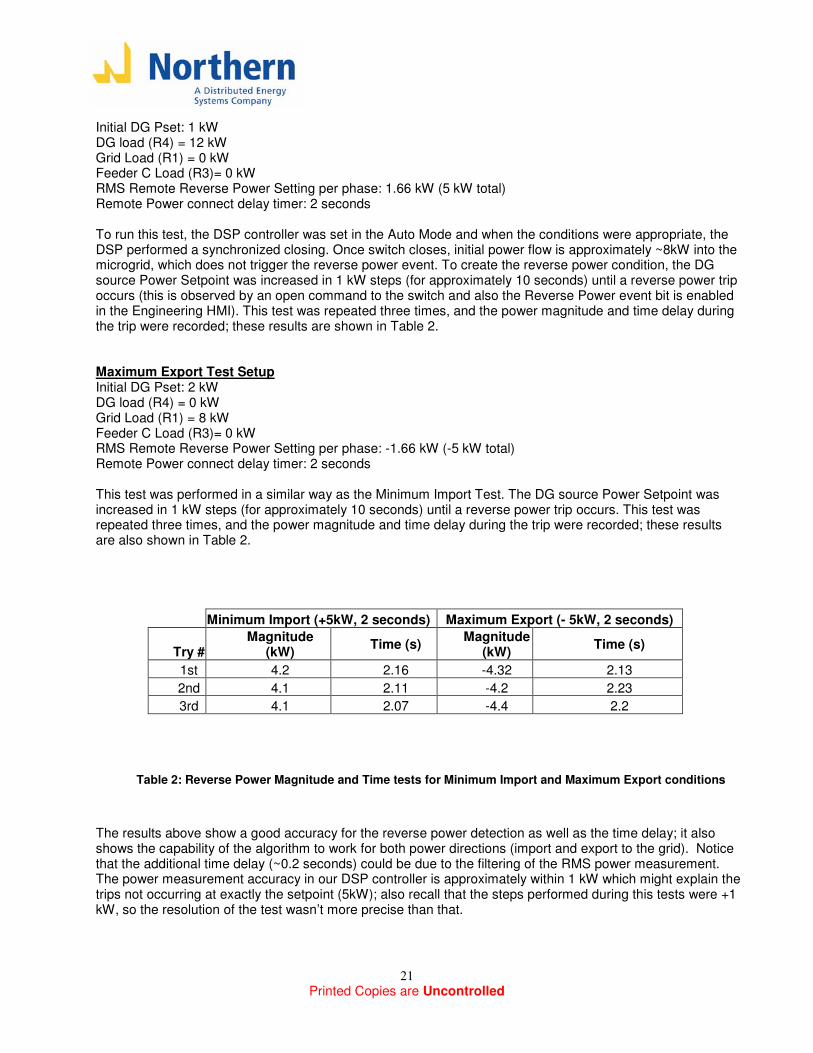
Initial DG Pset: 1 kW DG load (R4) = 12 kW Grid Load (R1) = 0 kW Feeder C Load (R3)= 0 kW RMS Remote Reverse Power Setting per phase: 1.66 kW (5 kW total) Remote Power connect delay timer: 2 seconds To run this test, the DSP controller was set in the Auto Mode and when the conditions were appropriate, the DSP performed a synchronized closing. Once switch closes, initial power flow is approximately ~8kW into the microgrid, which does not trigger the reverse power event. To create the reverse power condition, the DG source Power Setpoint was increased in 1 kW steps (for approximately 10 seconds) until a reverse power trip occurs (this is observed by an open command to the switch and also the Reverse Power event bit is enabled in the Engineering HMI). This test was repeated three times, and the power magnitude and time delay during the trip were recorded; these results are shown in Table 2. Maximum Export Test Setup Initial DG Pset: 2 kW DG load (R4) = 0 kW Grid Load (R1) = 8 kW Feeder C Load (R3)= 0 kW RMS Remote Reverse Power Setting per phase: -1.66 kW (-5 kW total) Remote Power connect delay timer: 2 seconds This test was performed in a similar way as the Minimum Import Test. The DG source Power Setpoint was increased in 1 kW steps (for approximately 10 seconds) until a reverse power trip occurs. This test was repeated three times, and the power magnitude and time delay during the trip were recorded; these results are also shown in Table 2.
Minimum Import (+5kW, 2 seconds) Maximum Export (- 5kW, 2 seconds)
Try # Magnitude
(kW) Time (s)
Magnitude (kW)
Time (s)
1st 4.2 2.16 -4.32 2.13
2nd 4.1 2.11 -4.2 2.23
3rd 4.1 2.07 -4.4 2.2
Table 2: Reverse Power Magnitude and Time tests for Minimum Import and Maximum Export conditions
The results above show a good accuracy for the reverse power detection as well as the time delay; it also shows the capability of the algorithm to work for both power directions (import and export to the grid). Notice that the additional time delay (~0.2 seconds) could be due to the filtering of the RMS power measurement. The power measurement accuracy in our DSP controller is approximately within 1 kW which might explain the trips not occurring at exactly the setpoint (5kW); also recall that the steps performed during this tests were +1 kW, so the resolution of the test wasn’t more precise than that.
Printed Copies are Uncontrolled
22
3.3.2 Grid islanding and Open Phase [Test Plan Section 3.6]
Using the reverse power algorithm tested in 3.3.1, an upstream grid islanding as well as an open phase condition can be detected. If this conditions occurs, it is expected that at least one phase of the grid voltage will be dead after the switch opens on the reverse power event; if the DSP controller observes this condition, then it will decide not to lockout the system, and thus allow to reclose when conditions are appropriate.
For the tests described above, and during normal operation, an additional setting is required:
- Voltage test delay timer: In seconds; once the reverse power event is enable, this new timer starts to run, and after it expires it looks at the voltage on the grid side (the switch should still be open from the reverse power event); if all the three phases voltages are normal, then it will create a fault and lockout the system, requiring user intervention; but if any of the phases voltage is low (grid islanding upstream or open-phase) then it will simply keep the switch open until conditions are appropriate for reclosing. For testing purposes, this timer will be set to 1 second.
Grid islanding and Open Phase Test Setup Initial DG Pset: 1 kW DG load (R4) = 8 kW Grid Load (R1) = 0 kW Feeder C Load= 0 kW RMS Remote Reverse Power Setting per phase: 1.66 kW (5 kW total) Remote Power connect delay timer: 2 seconds
The test setup described above was used for both the grid-islanding and the Open phase test. The grid islanding test condition was created by disconnecting the grid side inverter, thus no power flow exist across the switch which enables the reverse power event. The open-phase condition was created by disconnecting one of the phases on the grid side.
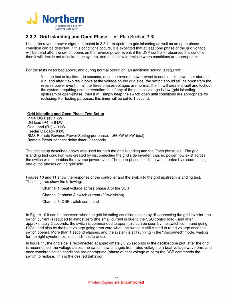
Figures 10 and 11 show the response of the controller and the switch to the grid upstream islanding test. These figures show the following:
Channel 1: beat voltage across phase A of the SCR
Channel 2: phase A switch current (20A/division)
Channel 3: DSP switch command
In Figure 10 it can be observed when the grid islanding condition occurs by disconnecting the grid inverter; the switch current is reduced to almost zero (the small current is due to the S&C control load), and after approximately 2 seconds, the switch is commanded to open (this can be seen by the switch command going HIGH, and also by the beat voltage going from zero when the switch is still closed to rated voltage once the switch opens). More than 1 second elapses, and the system is still running in the “Disconnect” mode, waiting for the right synchronization conditions to close.
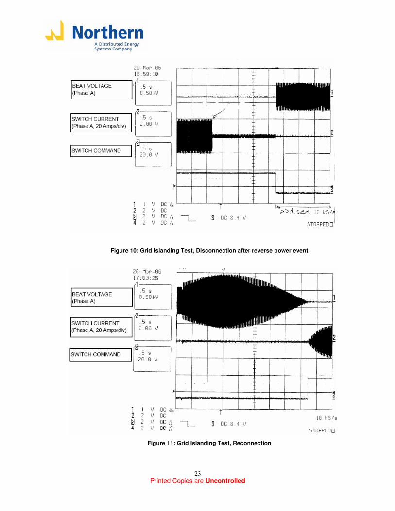
In figure 11, the grid side is reconnected at approximately 0.25 seconds in the oscilloscope plot; after the grid is reconnected, the voltage across the switch now changes from rated voltage to a beat voltage waveform, and once synchronization conditions are appropriate (phase of beat voltage at zero) the DSP commands the switch to reclose. This is the desired behavior.
Printed Copies are Uncontrolled
23
Figure 10: Grid Islanding Test, Disconnection after reverse power event
Figure 11: Grid Islanding Test, Reconnection
Printed Copies are Uncontrolled
24
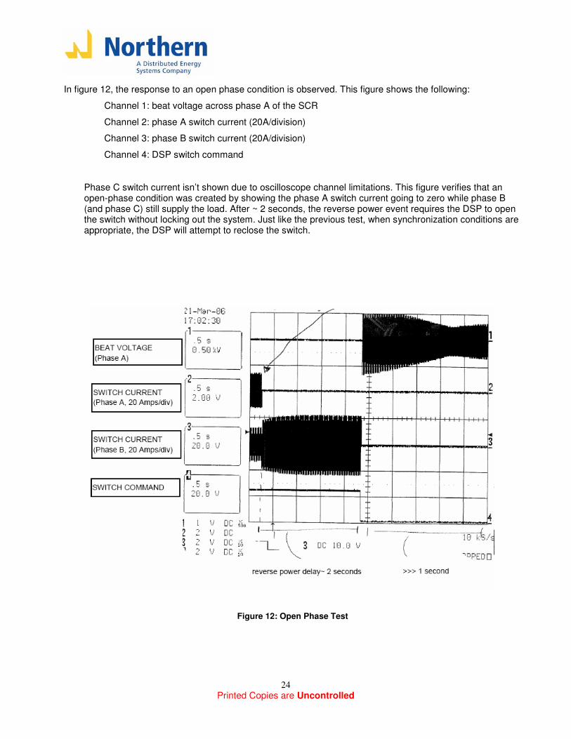
In figure 12, the response to an open phase condition is observed. This figure shows the following:
Channel 1: beat voltage across phase A of the SCR
Channel 2: phase A switch current (20A/division)
Channel 3: phase B switch current (20A/division)
Channel 4: DSP switch command
Phase C switch current isn’t shown due to oscilloscope channel limitations. This figure verifies that an open-phase condition was created by showing the phase A switch current going to zero while phase B (and phase C) still supply the load. After ~ 2 seconds, the reverse power event requires the DSP to open the switch without locking out the system. Just like the previous test, when synchronization conditions are appropriate, the DSP will attempt to reclose the switch.
Figure 12: Open Phase Test
Printed Copies are Uncontrolled
25
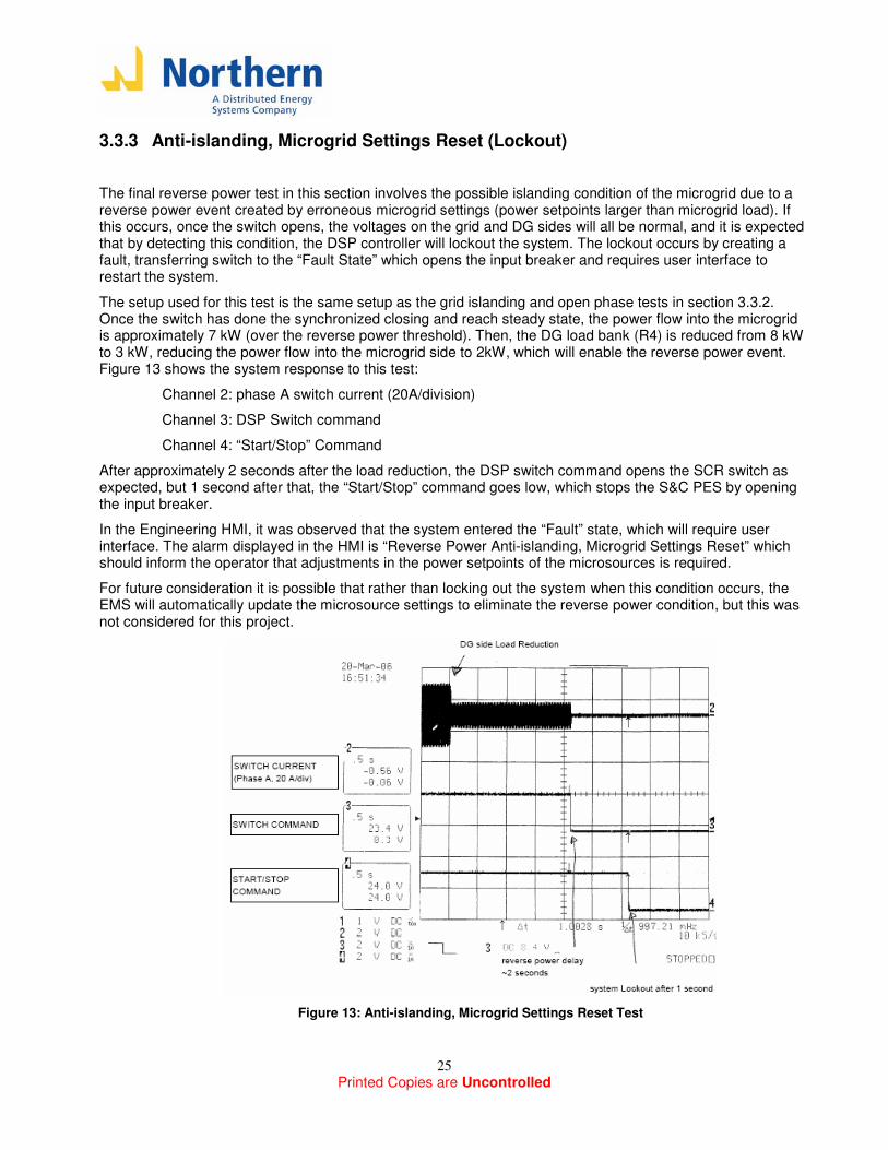
3.3.3 Anti-islanding, Microgrid Settings Reset (Lockout)
The final reverse power test in this section involves the possible islanding condition of the microgrid due to a reverse power event created by erroneous microgrid settings (power setpoints larger than microgrid load). If this occurs, once the switch opens, the voltages on the grid and DG sides will all be normal, and it is expected that by detecting this condition, the DSP controller will lockout the system. The lockout occurs by creating a fault, transferring switch to the “Fault State” which opens the input breaker and requires user interface to restart the system.
The setup used for this test is the same setup as the grid islanding and open phase tests in section 3.3.2. Once the switch has done the synchronized closing and reach steady state, the power flow into the microgrid is approximately 7 kW (over the reverse power threshold). Then, the DG load bank (R4) is reduced from 8 kW to 3 kW, reducing the power flow into the microgrid side to 2kW, which will enable the reverse power event. Figure 13 shows the system response to this test:
Channel 2: phase A switch current (20A/division)
Channel 3: DSP Switch command
Channel 4: “Start/Stop” Command
After approximately 2 seconds after the load reduction, the DSP switch command opens the SCR switch as expected, but 1 second after that, the “Start/Stop” command goes low, which stops the S&C PES by opening the input breaker.
In the Engineering HMI, it was observed that the system entered the “Fault” state, which will require user interface. The alarm displayed in the HMI is “Reverse Power Anti-islanding, Microgrid Settings Reset” which should inform the operator that adjustments in the power setpoints of the microsources is required.
For future consideration it is possible that rather than locking out the system when this condition occurs, the EMS will automatically update the microsource settings to eliminate the reverse power condition, but this was not considered for this project.
Figure 13: Anti-islanding, Microgrid Settings Reset Test
Printed Copies are Uncontrolled
26
3.4 IEEE 1547 Voltage and Frequency Tests
The IEEE 1547 standard specifies the voltage ranges and clearing times for over-voltage, under-voltage, over-frequency and under-frequency events. The values specified in the standard are repeated in each section for reference.
NREL’s Omicron CMA256-6 secondary injection test set was used to perform the IEEE 1547 voltage and frequency tests. These tests closely reflect the method required by the IEEE 1547.1 standard, where tests are repeated 5 times to get more accurate results. Two types of tests are performed:
- Magnitude Test: The Omicron equipment ramps the voltage or frequency up or down (depending on the setpoint tested) at a relatively slow rate, and stays at each level long enough to allow the DSP to give the trip command if necessary. The magnitude at which the trip occurs is recorded.
- Time test: The Omicron equipment ramp the voltage or frequency from rated level to just above or below the magnitude of the setpoint that is tested, and records the time delay of the switch command to trip.
As explained before, all these tests are run in the “Auto” model the Omicron Equipment simulates appropriate synchronization conditions on both the DG and Grid side PT secondary signals. After the DSP switch command goes high (close), it performs the tests mentioned above.
Also, it is important to note that these tests are performed at low power, so the S&C switch is off during this test; the time delays recorded relate to the DSP switch command, and does not include the opening time of the SCR (which is expected to be up to ½ cycles). The next subsection shows some tests that were done to verify the SCR opening time.
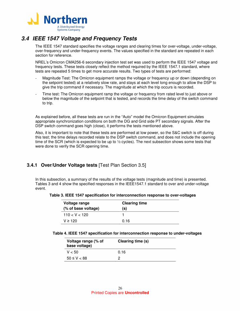
3.4.1 Over/Under Voltage tests [Test Plan Section 3.5]
In this subsection, a summary of the results of the voltage tests (magnitude and time) is presented. Tables 3 and 4 show the specified responses in the IEEE1547.1 standard to over and under-voltage event.
Table 3. IEEE 1547 specification for interconnection response to over-voltages
Voltage range
(% of base voltage)
Clearing time
(s)
110 < V < 120 1
V ≥ 120 0.16
Table 4. IEEE 1547 specification for interconnection response to under-voltages
Voltage range (% of base voltage)
Clearing time (s)
V < 50 0.16
50 ≤ V < 88 2
Printed Copies are Uncontrolled
27
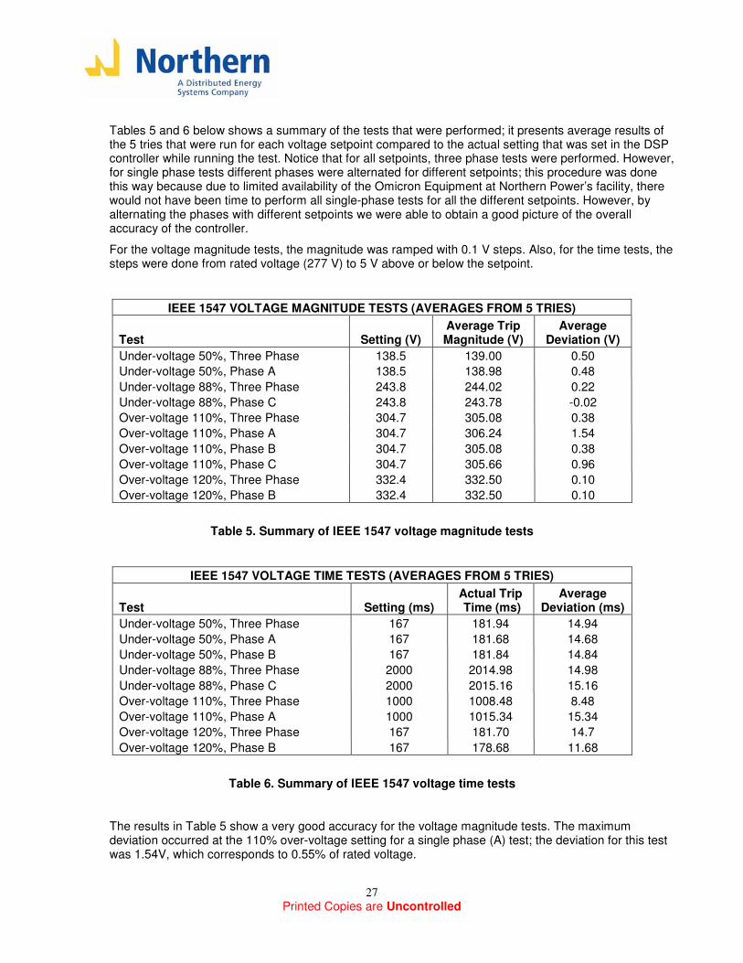
Tables 5 and 6 below shows a summary of the tests that were performed; it presents average results of the 5 tries that were run for each voltage setpoint compared to the actual setting that was set in the DSP controller while running the test. Notice that for all setpoints, three phase tests were performed. However, for single phase tests different phases were alternated for different setpoints; this procedure was done this way because due to limited availability of the Omicron Equipment at Northern Power’s facility, there would not have been time to perform all single-phase tests for all the different setpoints. However, by alternating the phases with different setpoints we were able to obtain a good picture of the overall accuracy of the controller.
For the voltage magnitude tests, the magnitude was ramped with 0.1 V steps. Also, for the time tests, the steps were done from rated voltage (277 V) to 5 V above or below the setpoint.
IEEE 1547 VOLTAGE MAGNITUDE TESTS (AVERAGES FROM 5 TRIES)
Test Setting (V) Average Trip Magnitude (V)
Average Deviation (V)
Under-voltage 50%, Three Phase 138.5 139.00 0.50
Under-voltage 50%, Phase A 138.5 138.98 0.48
Under-voltage 88%, Three Phase 243.8 244.02 0.22
Under-voltage 88%, Phase C 243.8 243.78 -0.02
Over-voltage 110%, Three Phase 304.7 305.08 0.38
Over-voltage 110%, Phase A 304.7 306.24 1.54
Over-voltage 110%, Phase B 304.7 305.08 0.38
Over-voltage 110%, Phase C 304.7 305.66 0.96
Over-voltage 120%, Three Phase 332.4 332.50 0.10
Over-voltage 120%, Phase B 332.4 332.50 0.10
Table 5. Summary of IEEE 1547 voltage magnitude tests
IEEE 1547 VOLTAGE TIME TESTS (AVERAGES FROM 5 TRIES)
Test Setting (ms) Actual Trip Time (ms)
Average Deviation (ms)
Under-voltage 50%, Three Phase 167 181.94 14.94
Under-voltage 50%, Phase A 167 181.68 14.68
Under-voltage 50%, Phase B 167 181.84 14.84
Under-voltage 88%, Three Phase 2000 2014.98 14.98
Under-voltage 88%, Phase C 2000 2015.16 15.16
Over-voltage 110%, Three Phase 1000 1008.48 8.48
Over-voltage 110%, Phase A 1000 1015.34 15.34
Over-voltage 120%, Three Phase 167 181.70 14.7
Over-voltage 120%, Phase B 167 178.68 11.68
Table 6. Summary of IEEE 1547 voltage time tests
The results in Table 5 show a very good accuracy for the voltage magnitude tests. The maximum deviation occurred at the 110% over-voltage setting for a single phase (A) test; the deviation for this test was 1.54V, which corresponds to 0.55% of rated voltage.
Printed Copies are Uncontrolled
28
The results in Table 6 also show good accuracies for the voltage time delays; the maximum deviation for the faster trips (167 ms) was less than 1 cycle (14.98 ms).
The IEEE 1547 under and over-voltage function tests results confirmed that the controller achieved its software programmed functionality.
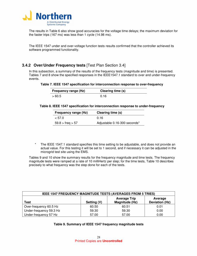
3.4.2 Over/Under Frequency tests [Test Plan Section 3.4]
In this subsection, a summary of the results of the frequency tests (magnitude and time) is presented. Tables 7 and 8 show the specified responses in the IEEE1547.1 standard to over and under-frequency events.
Table 7. IEEE 1547 specification for interconnection response to over-frequency
Frequency range (Hz) Clearing time (s)
> 60.5 0.16
Table 8. IEEE 1547 specification for interconnection response to under-frequency
Frequency range (Hz) Clearing time (s)
< 57.0 0.16
59.8 > freq > 57 Adjustable 0.16-300 seconds*
* The IEEE 1547.1 standard specifies this time setting to be adjustable, and does not provide an actual value. For this testing it will be set to 1 second, and if necessary it can be adjusted in the microgrid test site using the EMS.
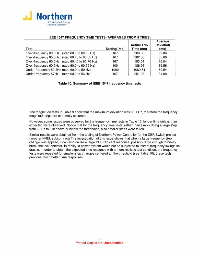
Tables 9 and 10 show the summary results for the frequency magnitude and time tests. The frequency magnitude tests were ramped at a rate of 10 milliHertz per step; for the time tests, Table 10 describes precisely to what frequency was the step done for each of the tests.
IEEE 1547 FREQUENCY MAGNITUDE TESTS (AVERAGES FROM 5 TRIES)
Test Setting (V) Average Trip
Magnitude (Hz) Average
Deviation (Hz)
Over-frequency 60.5 Hz 60.50 60.51 0.01
Under-frequency 59.3 Hz 59.30 59.30 0.00
Under-frequency 57 Hz 57.00 57.00 0.00
Table 9. Summary of IEEE 1547 frequency magnitude tests
Printed Copies are Uncontrolled
29
IEEE 1547 FREQUENCY TIME TESTS (AVERAGES FROM 5 TRIES)
Test Setting (ms) Actual Trip Time (ms)
Average Deviation
(ms)
Over-frequency 60.5Hz (step:60.0 to 60.55 Hz) 167 266.06 99.06
Over-frequency 60.5Hz (step:60.45 to 60.55 Hz) 167 202.66 35.66
Over-frequency 60.5Hz (step:60.40 to 60.70 Hz) 167 183.04 16.04
Over-frequency 60.5Hz (step:60.0 to 60.55 Hz) 100 186.56 86.56
Under-frequency 59.3Hz (step:60.0 to 59 Hz) 1000 1069.54 69.54
Under-frequency 57Hz (step:60.0 to 56 Hz) 167 251.08 84.08
Table 10. Summary of IEEE 1547 frequency time tests
The magnitude tests in Table 9 show that the maximum deviation was 0.01 Hz, therefore the frequency magnitude trips are extremely accurate.
However, some issues were observed for the frequency time tests in Table 10; longer time delays than expected were observed. Notice that for the frequency time tests, rather than simply doing a large step from 60 Hz to just above or below the thresholds, also smaller steps were taken.
Similar results were obtained from the testing of Northern Power Controller for the DER Switch project (another NREL subcontract) The investigation of this issue shows that when a large frequency step change was applied, it can also cause a large PLL transient response, possibly large enough to briefly break the lock detector. In reality, a power system would not be subjected to instant frequency swings so drastic. In order to obtain the expected time response with a more realistic test condition, the frequency tests were repeated for smaller step changes centered at the threshold (see Table 10); these tests provides much better time responses.
Printed Copies are Uncontrolled
30
3.5 SCR Switch Opening Time
In the IEEE 1547 section, the trip time measurement only monitored the opening command from the DSP Controller, and does not include the opening time of the switch (since the S&C PES was not powered). It was considered important to perform some runs and verify that unless an asymmetrical component is present in any of the switch currents, the SCR switch will open on approximately ½ cycles (8 ms).
To perform this test, a very simple test setup was used. The inverter side of the switch was setup as an open-loop source (constant voltage and frequency; 277V,60 Hz) while the other side of the switch was set to an 8 kW resistive load.
The test was operated in the “Manual” mode and “Sync Test Bypass”, so the switch could be manually opened and close. With this setup, the switch was cycled 20 times, and the opening time was recorded (from when the DSP command to open is given until all the phase currents go to zero).
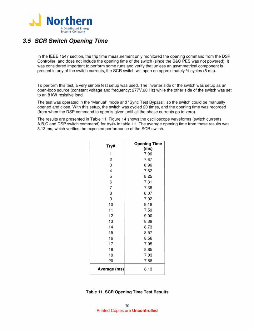
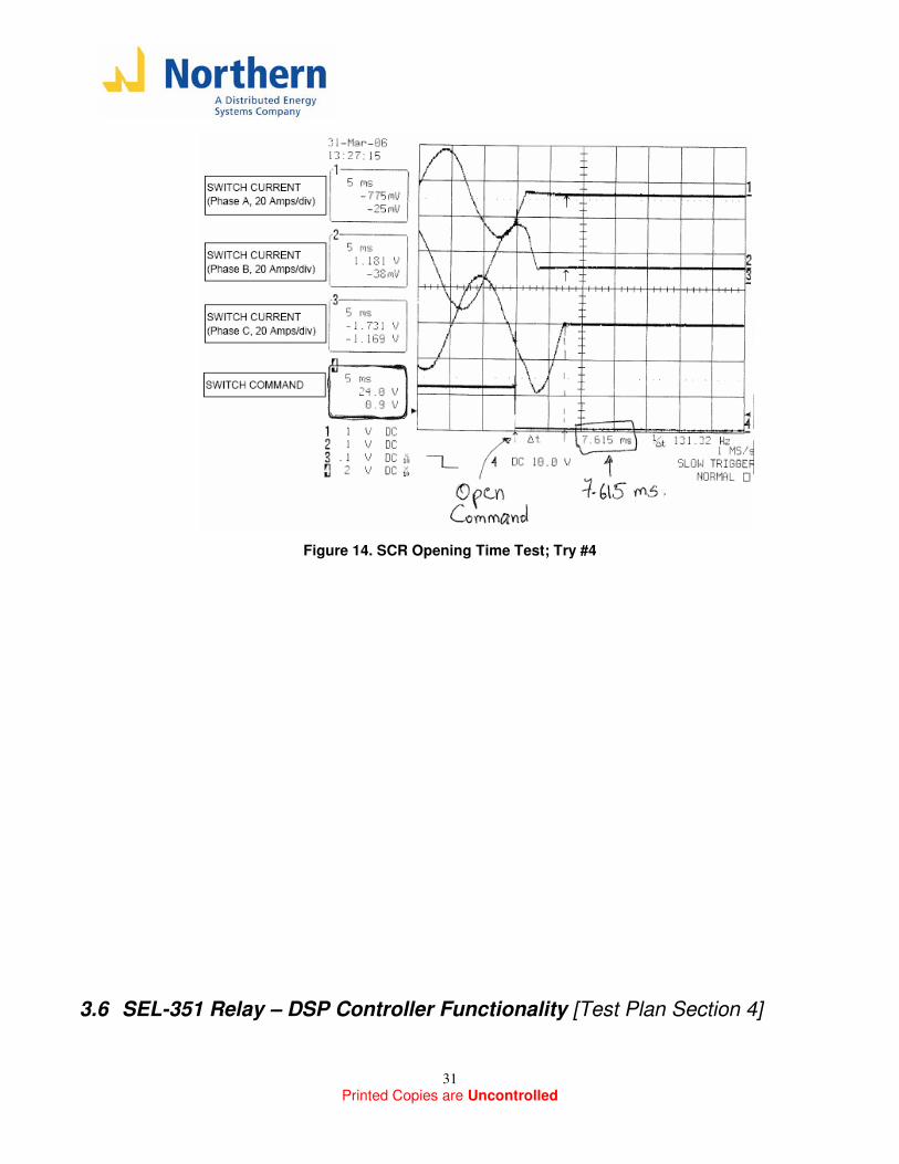
The results are presented in Table 11. Figure 14 shows the oscilloscope waveforms (switch currents A,B,C and DSP switch command) for try#4 in table 11. The average opening time from these results was 8.13 ms, which verifies the expected performance of the SCR switch.
Try# Opening Time
(ms)
1 7.96
2 7.67
3 8.96
4 7.62
5 8.25
6 7.31
7 7.38
8 8.07
9 7.92
10 9.18
11 7.59
12 9.00
13 8.39
14 8.73
15 8.57
16 8.56
17 7.95
18 8.85
19 7.03
20 7.68
Average (ms) 8.13
Table 11. SCR Opening Time Test Results
Printed Copies are Uncontrolled
31
Figure 14. SCR Opening Time Test; Try #4
3.6 SEL-351 Relay – DSP Controller Functionality [Test Plan Section 4]
Printed Copies are Uncontrolled
32
Several tests were performed to verify the basic functionality of the SEL-351 relay and its interaction with the Static Switch DSP control. The Relay input is considered an “Event” in the DSP controller; anytime the Relay communicates a trip to the DSP Controller, the DSP will give an opening command to the switch, no matter what the control mode is (recall that for the other events, such IEEE1547, Power Quality and Reverse Power, the DSP Controller opens the switch only in the “Auto” Mode)
As explained before, the Static Switch SEL 351 Relay (Relay2) is expected to perform the following protection functions:
- Phase overcurrent protection (instantaneous and time-overcurrent)
- Line to Line undervoltage protection (on the grid side of the switch PT14)
- Zero Sequence Current (using the neutral current input)
However, notice that for this set of tests, the programming of the SEL-351 relay was set to very simple trip levels and timers so that the trip conditions could be created based on the capabilities of the NPS test setup. The purpose is to test the interaction of Relay-DSP and not the trip accuracies of the Relay. The accuracies of the SEL-351 Relays can be trusted due to their wide use in the industry.
The tests performed in this section attempted to verify the following:
1) SEL Relay TRIP output logic 2) SEL Relay minimum opening time and associated DSP reconnection timer and reclosing 3) Relay to DSP delay
Settings
To perform the testing of this simple functionality, the Relay was programmed to the following settings (given in primary values):
- 50P1 (Instantaneous overcurrent): 15A - 27PP (Line-Line undervoltage): 50% - SV1 = 27PP (SV1 logic associated with line-line voltage) - SV1 Pickup time: 0 cycles - SV1 Dropout time: 5 seconds - Relay minimum opening time: 20 seconds - TRIP= 50P1+ SV1 - OUT101 =! TRIP (OUT101 is the output that will give the command to DSP)
3.6.1 SEL Relay TRIP output logic
The purpose of this test is to verify the output logic of the SEL-351. The DSP is expected to open the switch whenever the relay gives a trip command to it. There is no reconnection timers in the DSP associated with the Relay input (the final programming of the Relay will have its minimum opening time ~20 seconds in order to allow utility protection equipment to reclose first under fault conditions). OUT101 has been programmed with an inverse logic to the trip condition (!TRIP); also the DSP was programmed to the following logic:
- If input from Relay is HIGH (24V); keep switch closed - If input from Relay is LOW (0V); open switch
Printed Copies are Uncontrolled
33
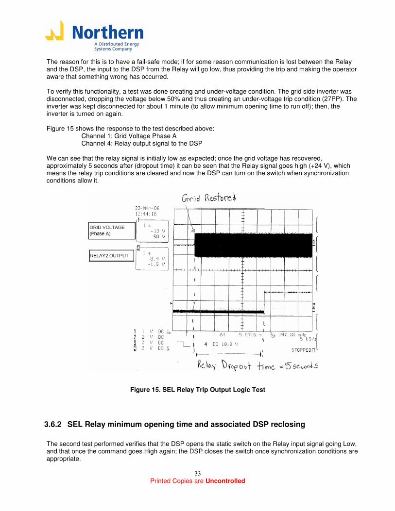
The reason for this is to have a fail-safe mode; if for some reason communication is lost between the Relay and the DSP, the input to the DSP from the Relay will go low, thus providing the trip and making the operator aware that something wrong has occurred. To verify this functionality, a test was done creating and under-voltage condition. The grid side inverter was disconnected, dropping the voltage below 50% and thus creating an under-voltage trip condition (27PP). The inverter was kept disconnected for about 1 minute (to allow minimum opening time to run off); then, the inverter is turned on again. Figure 15 shows the response to the test described above:
Channel 1: Grid Voltage Phase A Channel 4: Relay output signal to the DSP
We can see that the relay signal is initially low as expected; once the grid voltage has recovered, approximately 5 seconds after (dropout time) it can be seen that the Relay signal goes high (+24 V), which means the relay trip conditions are cleared and now the DSP can turn on the switch when synchronization conditions allow it.
Figure 15. SEL Relay Trip Output Logic Test
3.6.2 SEL Relay minimum opening time and associated DSP reclosing
The second test performed verifies that the DSP opens the static switch on the Relay input signal going Low, and that once the command goes High again; the DSP closes the switch once synchronization conditions are appropriate.
Printed Copies are Uncontrolled
34
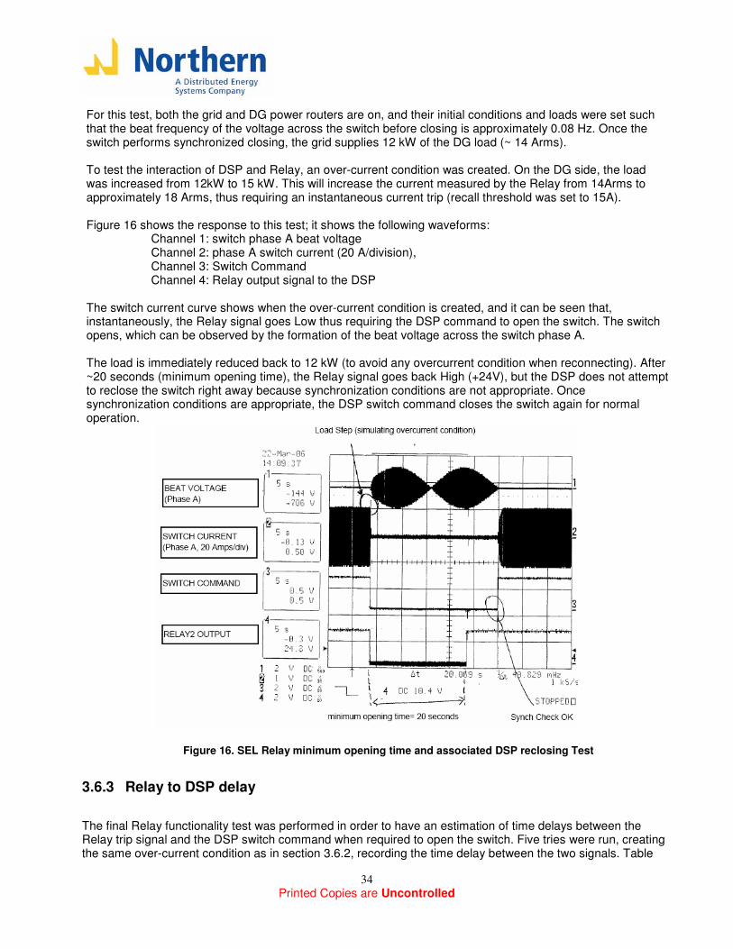
For this test, both the grid and DG power routers are on, and their initial conditions and loads were set such that the beat frequency of the voltage across the switch before closing is approximately 0.08 Hz. Once the switch performs synchronized closing, the grid supplies 12 kW of the DG load (~ 14 Arms). To test the interaction of DSP and Relay, an over-current condition was created. On the DG side, the load was increased from 12kW to 15 kW. This will increase the current measured by the Relay from 14Arms to approximately 18 Arms, thus requiring an instantaneous current trip (recall threshold was set to 15A). Figure 16 shows the response to this test; it shows the following waveforms:
Channel 1: switch phase A beat voltage Channel 2: phase A switch current (20 A/division), Channel 3: Switch Command Channel 4: Relay output signal to the DSP
The switch current curve shows when the over-current condition is created, and it can be seen that, instantaneously, the Relay signal goes Low thus requiring the DSP command to open the switch. The switch opens, which can be observed by the formation of the beat voltage across the switch phase A. The load is immediately reduced back to 12 kW (to avoid any overcurrent condition when reconnecting). After ~20 seconds (minimum opening time), the Relay signal goes back High (+24V), but the DSP does not attempt to reclose the switch right away because synchronization conditions are not appropriate. Once synchronization conditions are appropriate, the DSP switch command closes the switch again for normal operation.
Figure 16. SEL Relay minimum opening time and associated DSP reclosing Test
3.6.3 Relay to DSP delay
The final Relay functionality test was performed in order to have an estimation of time delays between the Relay trip signal and the DSP switch command when required to open the switch. Five tries were run, creating the same over-current condition as in section 3.6.2, recording the time delay between the two signals. Table
Printed Copies are Uncontrolled
35
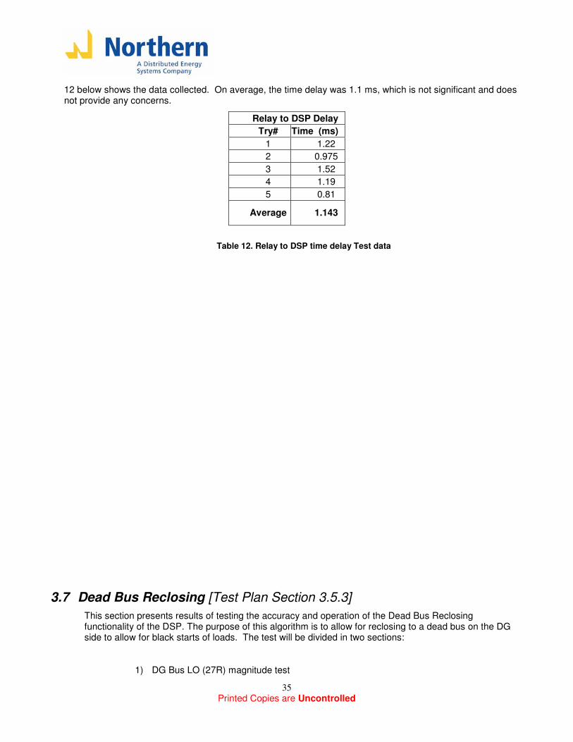
12 below shows the data collected. On average, the time delay was 1.1 ms, which is not significant and does not provide any concerns.
Relay to DSP Delay
Try# Time (ms)
1 1.22
2 0.975
3 1.52
4 1.19
5 0.81
Average 1.143
Table 12. Relay to DSP time delay Test data
3.7 Dead Bus Reclosing [Test Plan Section 3.5.3]
This section presents results of testing the accuracy and operation of the Dead Bus Reclosing functionality of the DSP. The purpose of this algorithm is to allow for reclosing to a dead bus on the DG side to allow for black starts of loads. The test will be divided in two sections:
1) DG Bus LO (27R) magnitude test
Printed Copies are Uncontrolled
36
2) DG Bus LO (27R) time test; “Dead Bus Reclose” operating mode
The settings for the algorithm during this test are:
Dead Bus 27R Magnitude: 15Vrms
Dead Bus 27R Time constant:: 1 second
3.7.1 DG Bus LO (27R) magnitude test
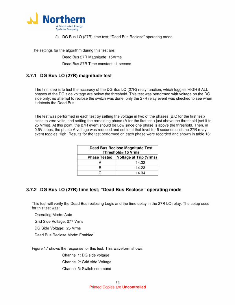
The first step is to test the accuracy of the DG Bus LO (27R) relay function, which toggles HIGH if ALL phases of the DG side voltage are below the threshold. This test was performed with voltage on the DG side only; no attempt to reclose the switch was done, only the 27R relay event was checked to see when it detects the Dead Bus.
The test was performed in each test by setting the voltage in two of the phases (B,C for the first test) close to zero volts, and setting the remaining phase (A for the first test) just above the threshold (set it to 25 Vrms). At this point, the 27R event should be Low since one phase is above the threshold. Then, in 0.5V steps, the phase A voltage was reduced and settle at that level for 5 seconds until the 27R relay event toggles High. Results for the test performed on each phase were recorded and shown in table 13:
Dead Bus Reclose Magnitude Test Threshold= 15 Vrms
Phase Tested Voltage at Trip (Vrms)
A 14.33
B 14.23
C 14.34
3.7.2 DG Bus LO (27R) time test; “Dead Bus Reclose” operating mode
This test will verify the Dead Bus reclosing Logic and the time delay in the 27R LO relay. The setup used for this test was:
Operating Mode: Auto
Grid Side Voltage: 277 Vrms
DG Side Voltage: 25 Vrms
Dead Bus Reclose Mode: Enabled
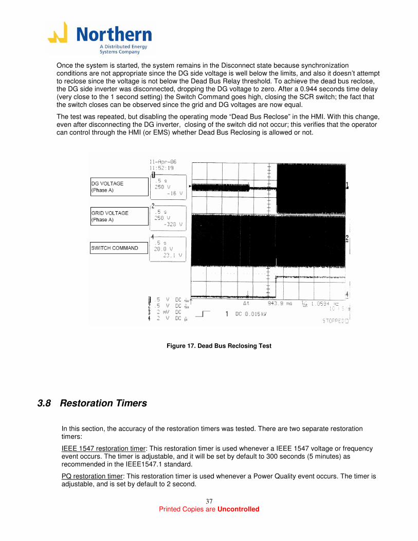
Figure 17 shows the response for this test. This waveform shows:
Channel 1: DG side voltage
Channel 2: Grid side Voltage
Channel 3: Switch command
Printed Copies are Uncontrolled
37
Once the system is started, the system remains in the Disconnect state because synchronization conditions are not appropriate since the DG side voltage is well below the limits, and also it doesn’t attempt to reclose since the voltage is not below the Dead Bus Relay threshold. To achieve the dead bus reclose, the DG side inverter was disconnected, dropping the DG voltage to zero. After a 0.944 seconds time delay (very close to the 1 second setting) the Switch Command goes high, closing the SCR switch; the fact that the switch closes can be observed since the grid and DG voltages are now equal.
The test was repeated, but disabling the operating mode “Dead Bus Reclose” in the HMI. With this change, even after disconnecting the DG inverter, closing of the switch did not occur; this verifies that the operator can control through the HMI (or EMS) whether Dead Bus Reclosing is allowed or not.
Figure 17. Dead Bus Reclosing Test
3.8 Restoration Timers
In this section, the accuracy of the restoration timers was tested. There are two separate restoration timers:
IEEE 1547 restoration timer: This restoration timer is used whenever a IEEE 1547 voltage or frequency event occurs. The timer is adjustable, and it will be set by default to 300 seconds (5 minutes) as recommended in the IEEE1547.1 standard.
PQ restoration timer: This restoration timer is used whenever a Power Quality event occurs. The timer is adjustable, and is set by default to 2 second.
Printed Copies are Uncontrolled
38
Additionally, it is important to mention that a “Disconnect” timer also exist in the DSP controller, this timer is not related to restoration conditions but rather to a minimum opening time for the switch. This timer is set by default to 1 second.
To test the IEEE1547 timer, a reverse power event due to a grid upstream was created (similar to section 3.3.2). Once the switch opens, since there is no voltage in the grid side, an IEEE1547 and a Power Quality event occur (this was verified by observing the alarms displayed in the Engineering HMI).
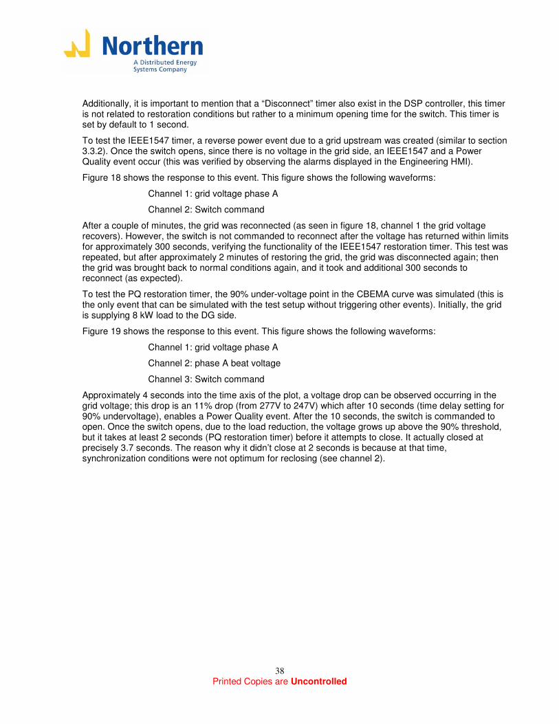
Figure 18 shows the response to this event. This figure shows the following waveforms:
Channel 1: grid voltage phase A
Channel 2: Switch command
After a couple of minutes, the grid was reconnected (as seen in figure 18, channel 1 the grid voltage recovers). However, the switch is not commanded to reconnect after the voltage has returned within limits for approximately 300 seconds, verifying the functionality of the IEEE1547 restoration timer. This test was repeated, but after approximately 2 minutes of restoring the grid, the grid was disconnected again; then the grid was brought back to normal conditions again, and it took and additional 300 seconds to reconnect (as expected).
To test the PQ restoration timer, the 90% under-voltage point in the CBEMA curve was simulated (this is the only event that can be simulated with the test setup without triggering other events). Initially, the grid is supplying 8 kW load to the DG side.
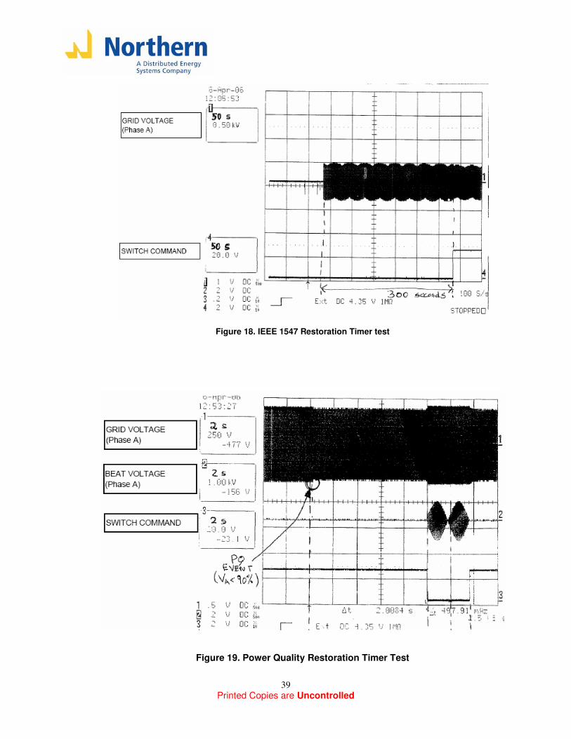
Figure 19 shows the response to this event. This figure shows the following waveforms:
Channel 1: grid voltage phase A
Channel 2: phase A beat voltage
Channel 3: Switch command
Approximately 4 seconds into the time axis of the plot, a voltage drop can be observed occurring in the grid voltage; this drop is an 11% drop (from 277V to 247V) which after 10 seconds (time delay setting for 90% undervoltage), enables a Power Quality event. After the 10 seconds, the switch is commanded to open. Once the switch opens, due to the load reduction, the voltage grows up above the 90% threshold, but it takes at least 2 seconds (PQ restoration timer) before it attempts to close. It actually closed at precisely 3.7 seconds. The reason why it didn’t close at 2 seconds is because at that time, synchronization conditions were not optimum for reclosing (see channel 2).
Printed Copies are Uncontrolled
39
Figure 18. IEEE 1547 Restoration Timer test
Figure 19. Power Quality Restoration Timer Test
Printed Copies are Uncontrolled
40
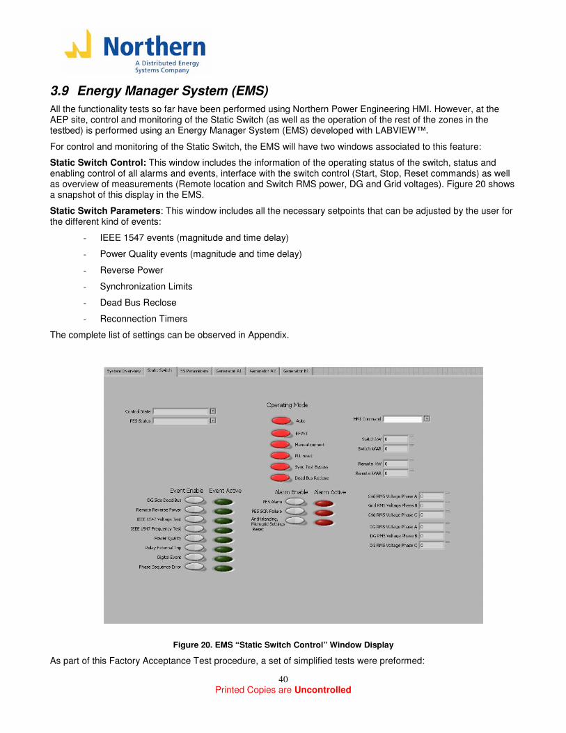
3.9 Energy Manager System (EMS)
All the functionality tests so far have been performed using Northern Power Engineering HMI. However, at the AEP site, control and monitoring of the Static Switch (as well as the operation of the rest of the zones in the testbed) is performed using an Energy Manager System (EMS) developed with LABVIEW™.
For control and monitoring of the Static Switch, the EMS will have two windows associated to this feature:
Static Switch Control: This window includes the information of the operating status of the switch, status and enabling control of all alarms and events, interface with the switch control (Start, Stop, Reset commands) as well as overview of measurements (Remote location and Switch RMS power, DG and Grid voltages). Figure 20 shows a snapshot of this display in the EMS.
Static Switch Parameters: This window includes all the necessary setpoints that can be adjusted by the user for the different kind of events:
- IEEE 1547 events (magnitude and time delay)
- Power Quality events (magnitude and time delay)
- Reverse Power
- Synchronization Limits
- Dead Bus Reclose
- Reconnection Timers
The complete list of settings can be observed in Appendix.
Figure 20. EMS “Static Switch Control” Window Display
As part of this Factory Acceptance Test procedure, a set of simplified tests were preformed:
Printed Copies are Uncontrolled
41
HMI Command: The HMI Command includes the “Start”, “Stop” and “Reset” command. These commands were cycled around about 5 times, and the expected response of switch was observed (by opening and closing the input breaker, or by Resetting any alarms that appear).
Control State: The Control State window display in which state of the DSP Controller State Machine the system is at the moment. These states include:
- OFF
- FAULT
- DISABLE
- TEST
- CONNECT, DISCONNECT
To test this feature, some simple functionality tests from the previous sections were performed, and it was observed that this display will show the correct state in which the switch was at the moment (which was also the case when using the Engineering HMI).
PES Status: The Control State window display in which state of the S&C PES is at the moment. These states include:
- PES OK (running, no alarms, but the switch open)
- PES Closed
- PES Alarm
- PES SCR failure
- PES Warning
To test this feature, several open/close of the switch as well as alarm conditions were created, and the expected display was observed. To understand in full detail the meaning of each of this alarm, check Reference [2].
Events and Alarms: All the events and alarms that the DSP Controller will be monitoring have to bit associated with them:
- Enable: When this event is on, the switch will be checking this event, if not, the event is disabled
- Active: Indicator that tells whether conditions that create this event or alarm are present at the moment.
To test the “Enable” bit, overcurrent condition was created (same as section 3.6.2) which requires and External Relay trip; it was observed that, with the “External Relay Trip” event enabled, the Active indicator for this event was on, and the switch goes to disconnect state on this event. Then, the test was repeated but the “Relay trip event” was disable, and in this condition no opening of the switch occurs as expected.
To test the “Active” bit, a reverse power condition requiring anti-islanding lockout (section 3.3.3); once the switch command the system to “Stop” the “Anti-islanding Microgrid Settings Reset” indicator turns on as expected, communicating the operator that adjustments of power setpoints in the DG sources is required.
Printed Copies are Uncontrolled
42
3.10 CERTS Switch Full Functionality Test
The purpose of these section is to verify the complete functionality of CERTS switch Controller by creating events that will simulate all the conditions tested previously, but while having all the functions Enabled (with all the default functions and settings when the Switch goes to the AEP site). Also, during all these tests, the interface between the operator the DSP controller will be the Energy Manager System (EMS) only. Below, a description of all the tests performed is included. All the tests were run continuously without stopping the system (unless required by the control logic); during all these tests, all signals and alarms are checked in the EMS to see if it operates as expected. In each of the tests below, a brief summary with observations of the CERTS switch response is presented. CERTS Switch Full Functionality Test Initial System Setup Grid side - Grid inverter voltage setpoint: 277V - Grid inverter Frequency: 60 Hz - Grid Load (R1) = 0 kW DG side - DG inverter Power Setpoint= 1 kW - DG inverter droop= 0.05 Hz/kW (assuming Fmin=59.3Hz, Pmax=15 kW) - DG Load (R4)= 12kW - Frequency (before closing) ~ 59.45 Hz DSP Default Setpoints
- Synchronization frequency limits: (Nominal= 60Hz, Freq min= 59Hz, Freq max= 61 Hz) - Synchronization voltage limits: (Nominal = 277V,Voltage min= 305V (110 %), Voltage max= 250V (90%) - Synchronizations phase outer limits: 10, -10 degrees - Reverse power per phase= 3.33 kW (10 kW total) - Reverse power time delay= 2 seconds - Reverse power voltage test delay (for lockout decision) = 0.5 seconds - IEEE 1547 voltage, frequency points: based on IEEE 1547.1 standard (same settings tested in section
3.4; tables 4,5,8,9) - Power Quality: Based on CBEMA, SEMIF47 standard (4 undervoltages and 3 overvoltages; check
Reference [2]). The testpoint that will be tested in this process is:
o Voltage #7 (sag): magnitude=90% (249.3 Vrms), time delay= 10 seconds - Dead Bus reclose test voltage: 15 V - Dead bus reclose test time delay: 1 second
Printed Copies are Uncontrolled
43
- Reconnection timer for PQ events: 2 seconds - Reconnection timer for IEEE1547 events: 300 seconds - Disconnect timer: 1 second SEL 351 Relay2 Settings - 50P1 (Instantaneous overcurrent): 15A - Relay minimum opening time: 20 seconds - TRIP= 50P1+ SV1 - OUT101 =! TRIP (OUT101 is the output that will give the command to DSP) Note: under-voltage protection was not included in the Relay programming for this test so it wouldn’t interfere with the IEE1547 and Power Quality voltage tests.
Test #1: Start up system, Synchronized Closing The initial setup of the DG and grid side will provide a beat frequency of about 0.55 Hz.. Also all voltages should be within the default synchronization limits so system should be ready to automatically performed a synchronized closing.
• Measurements were setup to observe:
• Voltage across phase A of the switch
• Phase A switch current. The following steps were performed: 1) Make sure all alarms are reset on both the S&C PES and DSP, and that system is ready to start. (S&C
PES should be in “Output disconnect” mode) 2) Start the system with the “Start” command. The system should enter the “Disconnect” State on the DSP,
and we should observe the beat voltage with a frequency of approximately ~0.2 Hz. 3) After passing through a zero crossing in the beat voltage, the DSP should provide a “Close” command to
the PES and the switch will close. Should see the beat voltage drop to approximately zero Volts, and the switch current should increase to approximately 14Arms (the Grid needs to supply 12 of the 15kW in the DG side)
Observations: The response of the CERTS switch during this test was as expected; once the system was started, synchronization closing occurred with a very smooth transition. After waiting a few minutes, the switch remaining closed without any alarms or events, meaning the system is in normal operation. When the switch closes, “CONNECT” is displayed in the Control State block of the EMS, and “PES OK” is displayed in the PES Status block.
Test #2: Reverse power due to grid islanding (Check for IEEE1547 voltage event) For this test, monitor:
• Switch command
• Grid side voltage phase A
• Voltage across phase A of the switch
• Switch current phase A 1) Disconnect grid side inverter from system. The switch current should drop from 14Arms to zero since the
grid is gone and won’t be providing any power (in any of the phases) to the DG side of the switch.
Printed Copies are Uncontrolled
44
2) After two seconds, the DSP should provide an open command to the S&C PES due to a reverse power event. The beat voltage in Phase A should change from zero to approximately rated voltage (since DG side: rated voltage and Grid side: 0 V). Switch current remains zero since switch is opened. Observe the “Events Active” list in the EMS. Once the switch opens, verify that the “IEEE1547 voltage type test” turn on, due to the fact that once the switch opens, the voltage on the grid side PT drops to zero.(Notice that the “Power Quality Function” event also should turn on)
3) Wait for ~20-30 seconds, and observe that the “IEEE1547 voltage type test” event remain high. 4) Reconnect the grid inverter to bring the grid voltage back. The “IEEE1547 voltage type test” event should
toggle back low since the grid voltage is back to normal, but switch shouldn’t try to reclose due to IEEE1547 reconnection timer being 300 seconds.
5) Observe the beat voltage of the switch phase A (which should again be a beat waveform with ~0.2Hz frequency). After approximately 5 minutes, once synchronization conditions are appropriate, it should reclose. Switch current should go back to ~14 Arms.
Observations: The response of the CERTS switch during this test was as expected; the switch is disconnected 2.05 seconds after the reverse power event occurs. When the switch opens, “DISCONNECT” is displayed in the Control State block of the EMS, and “PES OPEN” is displayed in the PES Status block. In the Events list, the “IEEE1547 voltage type test” and “Power Quality Function” events are on. Once the grid was reconnected, it took over 300 seconds (~305 seconds) for the switch to reclose. The Control State and PES Status block returned to “CONNECT” and “PES CLOSED” respectively.
Test #3: Reverse power due to open phase (Also check for IEEE1547 voltage event) For this test, monitor:
• Switch command
• Grid side voltage phase A
• Voltage across phase A of the switch
• Switch current phasse A and B 1) Disconnect grid side phase A from system by using a single phase contactor. Phase A current should
drop from ~14Arms to zero while phase B (and C) currents increase a bit. Also, grid Phase A to neutral voltage should drop to zero, but phase B (and C) will remain approximately at rated voltage.
2) After two seconds, the DSP should provide an open command to the PES due to a reverse power event (setting is at 3.3kW per phase). The beat voltage in Phase A should change from zero to approximately rated voltage (since DG=rated voltage and Grid=0 V). Now both phase A and B switch current drop to zero since switch is opened.
3) Observe the “Alarms” menu in the HMI display. Once the switch opens, we should see the “IEEE1547 voltage type test” event go high, due to the fact that one of the phases (phase A) the voltage on the grid side PT drops to zero.
4) Wait for ~20-30 seconds, and observe that the “IEEE1547 voltage type test” event remains high 5) Close the single-phase contactor to bring phase A grid voltage back. The “IEEE1547 voltage type test”
event should toggle back low since the grid voltage is back to normal, but switch shouldn’t try to reclose due to IEEE1547 reconnection timer being 300 seconds.
6) Observe the beat voltage A (which should again be a waveform with ~0.2Hz frequency). After approximately 5 minutes, once synchronization conditions are appropriate, it should reclose. Switch current should go back to ~14 Arms.
Observations: Same as Test #2
Printed Copies are Uncontrolled
45
Test #4: Reverse power Anti-islanding, Microgrid Settings Reset (Check Anti-islanding lockout logic) For this test, monitor:
• Switch command
• Start/Stop Command
• Grid side Voltage phase A
• Switch Current phase A 1) Currently, the grid is supplying ~11 kW to the DG side (monitored by the remote CT12 current
transformers). 2) Change the DG setpoint from 1 kW to 4 kW. This will require the grid to supply a per phase power of
~2.66 kW, just below the threshold (3.3 kW per phase). 3) After 2 seconds, a reverse power event occurs, so the Switch command should open the S&C PES. 4) Approximately 0.5 seconds after the trip, the reverse power voltage test algorithm will see that all the
voltages on the grid side are normal. This will create a fault condition that requires the switch to lockout. The DSP will provide a “Stop” command to the PES, opening the input breaker and keeping the DSP state machine in the “Fault” state.
5) Restart the system. The switch should performed automatically a synchronized closing, but two seconds fter that it will see the reverse power condition again, and lockout the system
6) Change the microgrid setpoint back to 3kW. 7) Restart the system. The system should perform the synchronized close. Wait for 1 minute, and we should
see no alarms or events come on. Observations: The CERTS Switch controller responded as expected; the reverse power event transition the switch to the “DISCONNECT” State, but after 0.5 seconds, the switch was commanded to Stop and the input breaker was Open. The Control State Block display “Fault- Anti-islanding Microgrid Settings Reset”. Faults were cleared and the switch Started. After attempting the first switch reclosing (without adjusting the DG setpoint back to 1 kW) the switch closed by opened and Stop again. Once the DG setpoint was adjusted back to 1 kW, the switch closed and remained in the “CONNECT” State.
Test #5: Power Quality Event
• For this test, monitor:
• Switch command
• Grid side Voltage phase A
• Voltage across switch phase A 1) Drop all phases of the grid side voltage from rated voltage to 91% (252Vrms) 2) Drop phase A by 0.5% (1.38V). Wait for ~ 30 seconds; no events should occur. 3) Repeat step 2 until a PQ event (and no IEEE1547) occurs. The event should occur approximately 10
seconds after the voltage step is performed. 4) Once the event occurs, the Switch Command should open the switch.

Printed Copies are Uncontrolled
46
5) Observe the “Power Quality” event go high. No other events should be enabled at this point. 6) Wait for ~ 1 minute. 7) Step the phase A voltage back to 100% (277Vrms). Approximately two seconds (PQ reconnection timer)
after the step, the switch should attempt to reclose (once synchronization conditions are acceptable) 8) System goes back to normal, no alarms present. Observations: CERTS Switch responded appropriately; in the events list on the EMS, the “Power Quality Function” event turn on, and after 9.7 seconds of the voltage step, the switch was commanded to open and transitioned to the “DISCONNECT” state. The voltage came back within the Power Quality thresholds (>90%) almost immediately (since there is no voltage drop across the grid inverter transformers). The switch reconnected after 3.7 seconds rather than 2 seconds (PQ restoration timer) because synchronization conditions were not appropriate yet.
Test # 6: SEL351 Relay2 Event For this test, monitor:
• Switch command
• Relay Output Signal
• Switch Current Phase A
• Voltage across switch phase A. 1) After the switch recloses in the final step of test #5, the switch current is approximately ~14 A rms (12 kW
supplied by grid). 2) Check the Relay current readings (in the display panel); the three phases should be approximately 14
Arms. 3) Increase the DG side load to 15 kW.. The current now will increase to ~18 Arms. Since the overcurrent
level in the relay was set to 15 Arms, then the relay should provide a trip command to the DSP, and the DSP should command the switch to open instantaneously. Reduce the DG load back to 12 kW.
4) Check that the “Relay Trip event” alarm goes high. 5) After ~20 seconds (relay minimum opening time) the relay trip signal will go off, and the DSP will
immediately try to reclose the switch. Observations: The CERTS Switch controller responded as expected; when the DG side load was increased, the Relay Output signal went Low, and the Switch command immediately opened the switch. At this time, the “Relay External Trip” event turned on, and all other alarms and events remained off. After 20 seconds, the Relay Output signal toggle HIGH again, and after an additional ~1.8 seconds, the DSP reclosed the switch (once synchronization conditions were appropriate).
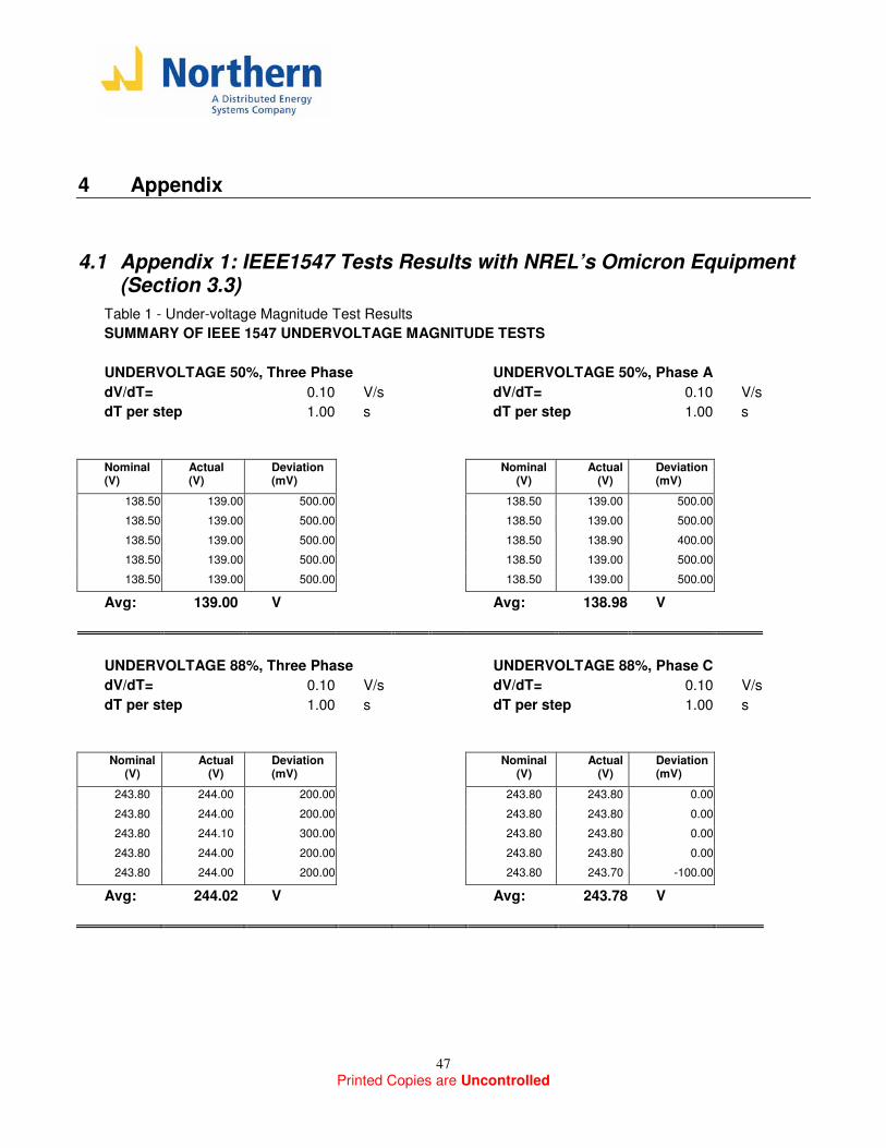
Printed Copies are Uncontrolled
47
4 Appendix
4.1 Appendix 1: IEEE1547 Tests Results with NREL’s Omicron Equipment (Section 3.3)
Table 1 - Under-voltage Magnitude Test Results
SUMMARY OF IEEE 1547 UNDERVOLTAGE MAGNITUDE TESTS
UNDERVOLTAGE 50%, Three Phase UNDERVOLTAGE 50%, Phase A
dV/dT= 0.10 V/s dV/dT= 0.10 V/s
dT per step 1.00 s dT per step 1.00 s
Nominal (V)
Actual (V)
Deviation (mV)
Nominal (V)
Actual (V)
Deviation (mV)
138.50 139.00 500.00 138.50 139.00 500.00 138.50 139.00 500.00 138.50 139.00 500.00 138.50 139.00 500.00 138.50 138.90 400.00 138.50 139.00 500.00 138.50 139.00 500.00 138.50 139.00 500.00 138.50 139.00 500.00
Avg: 139.00 V Avg: 138.98 V
UNDERVOLTAGE 88%, Three Phase UNDERVOLTAGE 88%, Phase C
dV/dT= 0.10 V/s dV/dT= 0.10 V/s
dT per step 1.00 s dT per step 1.00 s
Nominal
(V) Actual
(V) Deviation (mV)
Nominal (V)
Actual (V)
Deviation (mV)
243.80 244.00 200.00 243.80 243.80 0.00 243.80 244.00 200.00 243.80 243.80 0.00 243.80 244.10 300.00 243.80 243.80 0.00 243.80 244.00 200.00 243.80 243.80 0.00 243.80 244.00 200.00 243.80 243.70 -100.00
Avg: 244.02 V Avg: 243.78 V
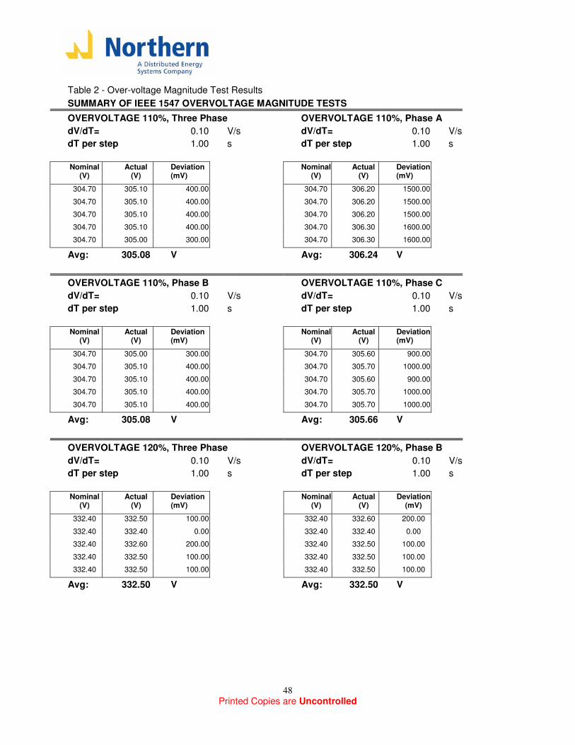
Printed Copies are Uncontrolled
48
Table 2 - Over-voltage Magnitude Test Results
SUMMARY OF IEEE 1547 OVERVOLTAGE MAGNITUDE TESTS
OVERVOLTAGE 110%, Three Phase OVERVOLTAGE 110%, Phase A
dV/dT= 0.10 V/s dV/dT= 0.10 V/s
dT per step 1.00 s dT per step 1.00 s
Nominal
(V) Actual
(V) Deviation (mV)
Nominal (V)
Actual (V)
Deviation (mV)
304.70 305.10 400.00 304.70 306.20 1500.00 304.70 305.10 400.00 304.70 306.20 1500.00 304.70 305.10 400.00 304.70 306.20 1500.00 304.70 305.10 400.00 304.70 306.30 1600.00 304.70 305.00 300.00 304.70 306.30 1600.00
Avg: 305.08 V Avg: 306.24 V
OVERVOLTAGE 110%, Phase B OVERVOLTAGE 110%, Phase C
dV/dT= 0.10 V/s dV/dT= 0.10 V/s
dT per step 1.00 s dT per step 1.00 s
Nominal
(V) Actual
(V) Deviation (mV)
Nominal (V)
Actual (V)
Deviation (mV)
304.70 305.00 300.00 304.70 305.60 900.00 304.70 305.10 400.00 304.70 305.70 1000.00 304.70 305.10 400.00 304.70 305.60 900.00 304.70 305.10 400.00 304.70 305.70 1000.00 304.70 305.10 400.00 304.70 305.70 1000.00
Avg: 305.08 V Avg: 305.66 V
OVERVOLTAGE 120%, Three Phase OVERVOLTAGE 120%, Phase B
dV/dT= 0.10 V/s dV/dT= 0.10 V/s
dT per step 1.00 s dT per step 1.00 s
Nominal
(V) Actual
(V) Deviation (mV)
Nominal (V)
Actual (V)
Deviation (mV)
332.40 332.50 100.00 332.40 332.60 200.00 332.40 332.40 0.00 332.40 332.40 0.00 332.40 332.60 200.00 332.40 332.50 100.00 332.40 332.50 100.00 332.40 332.50 100.00 332.40 332.50 100.00 332.40 332.50 100.00
Avg: 332.50 V Avg: 332.50 V
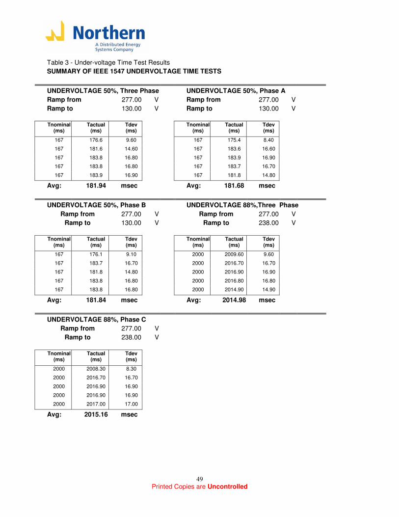
Printed Copies are Uncontrolled
49
Table 3 - Under-voltage Time Test Results
SUMMARY OF IEEE 1547 UNDERVOLTAGE TIME TESTS
UNDERVOLTAGE 50%, Three Phase UNDERVOLTAGE 50%, Phase A
Ramp from 277.00 V Ramp from 277.00 V
Ramp to 130.00 V Ramp to 130.00 V
Tnominal
(ms) Tactual
(ms) Tdev (ms)
Tnominal (ms)
Tactual (ms)
Tdev (ms)
167 176.6 9.60 167 175.4 8.40 167 181.6 14.60 167 183.6 16.60 167 183.8 16.80 167 183.9 16.90 167 183.8 16.80 167 183.7 16.70 167 183.9 16.90 167 181.8 14.80
Avg: 181.94 msec Avg: 181.68 msec
UNDERVOLTAGE 50%, Phase B UNDERVOLTAGE 88%,Three Phase
Ramp from 277.00 V Ramp from 277.00 V
Ramp to 130.00 V Ramp to 238.00 V
Tnominal
(ms) Tactual
(ms) Tdev (ms)
Tnominal (ms)
Tactual (ms)
Tdev (ms)
167 176.1 9.10 2000 2009.60 9.60 167 183.7 16.70 2000 2016.70 16.70 167 181.8 14.80 2000 2016.90 16.90 167 183.8 16.80 2000 2016.80 16.80 167 183.8 16.80 2000 2014.90 14.90
Avg: 181.84 msec Avg: 2014.98 msec
UNDERVOLTAGE 88%, Phase C
Ramp from 277.00 V
Ramp to 238.00 V
Tnominal
(ms) Tactual
(ms) Tdev (ms)
2000 2008.30 8.30 2000 2016.70 16.70 2000 2016.90 16.90 2000 2016.90 16.90 2000 2017.00 17.00
Avg: 2015.16 msec
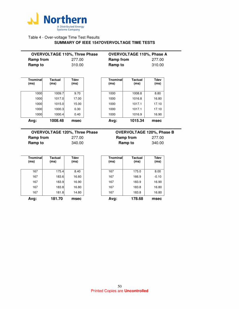
Printed Copies are Uncontrolled
50
Table 4 - Over-voltage Time Test Results
SUMMARY OF IEEE 1547OVERVOLTAGE TIME TESTS
OVERVOLTAGE 110%, Three Phase OVERVOLTAGE 110%, Phase A
Ramp from 277.00 Ramp from 277.00
Ramp to 310.00 Ramp to 310.00
Tnominal (ms)
Tactual (ms)
Tdev (ms)
Tnominal (ms)
Tactual (ms)
Tdev (ms)
1000 1009.7 9.70 1000 1008.8 8.80 1000 1017.0 17.00 1000 1016.8 16.80 1000 1015.0 15.00 1000 1017.1 17.10 1000 1000.3 0.30 1000 1017.1 17.10 1000 1000.4 0.40 1000 1016.9 16.90
Avg: 1008.48 msec Avg: 1015.34 msec
OVERVOLTAGE 120%, Three Phase OVERVOLTAGE 120%, Phase B
Ramp from 277.00 Ramp from 277.00
Ramp to 340.00 Ramp to 340.00
Tnominal (ms)
Tactual (ms)
Tdev (ms)
Tnominal (ms)
Tactual (ms)
Tdev (ms)
167 175.4 8.40 167 175.0 8.00 167 183.6 16.60 167 166.9 -0.10 167 183.9 16.90 167 183.9 16.90 167 183.8 16.80 167 183.8 16.80 167 181.8 14.80 167 183.8 16.80
Avg: 181.70 msec Avg: 178.68 msec
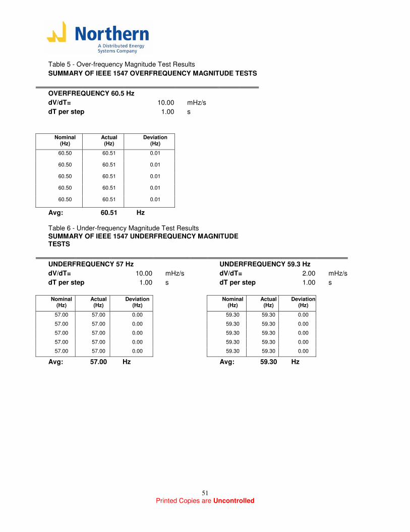
Printed Copies are Uncontrolled
51
Table 5 - Over-frequency Magnitude Test Results
SUMMARY OF IEEE 1547 OVERFREQUENCY MAGNITUDE TESTS
OVERFREQUENCY 60.5 Hz
dV/dT= 10.00 mHz/s
dT per step 1.00 s
Nominal
(Hz) Actual
(Hz) Deviation
(Hz) 60.50 60.51 0.01
60.50 60.51 0.01
60.50 60.51 0.01
60.50 60.51 0.01
60.50 60.51 0.01
Avg: 60.51 Hz Table 6 - Under-frequency Magnitude Test Results
SUMMARY OF IEEE 1547 UNDERFREQUENCY MAGNITUDE TESTS
UNDERFREQUENCY 57 Hz UNDERFREQUENCY 59.3 Hz
dV/dT= 10.00 mHz/s dV/dT= 2.00 mHz/s
dT per step 1.00 s dT per step 1.00 s
Nominal
(Hz) Actual
(Hz) Deviation
(Hz)
Nominal (Hz)
Actual (Hz)
Deviation (Hz)
57.00 57.00 0.00 59.30 59.30 0.00 57.00 57.00 0.00 59.30 59.30 0.00 57.00 57.00 0.00 59.30 59.30 0.00 57.00 57.00 0.00 59.30 59.30 0.00 57.00 57.00 0.00 59.30 59.30 0.00
Avg: 57.00 Hz Avg: 59.30 Hz
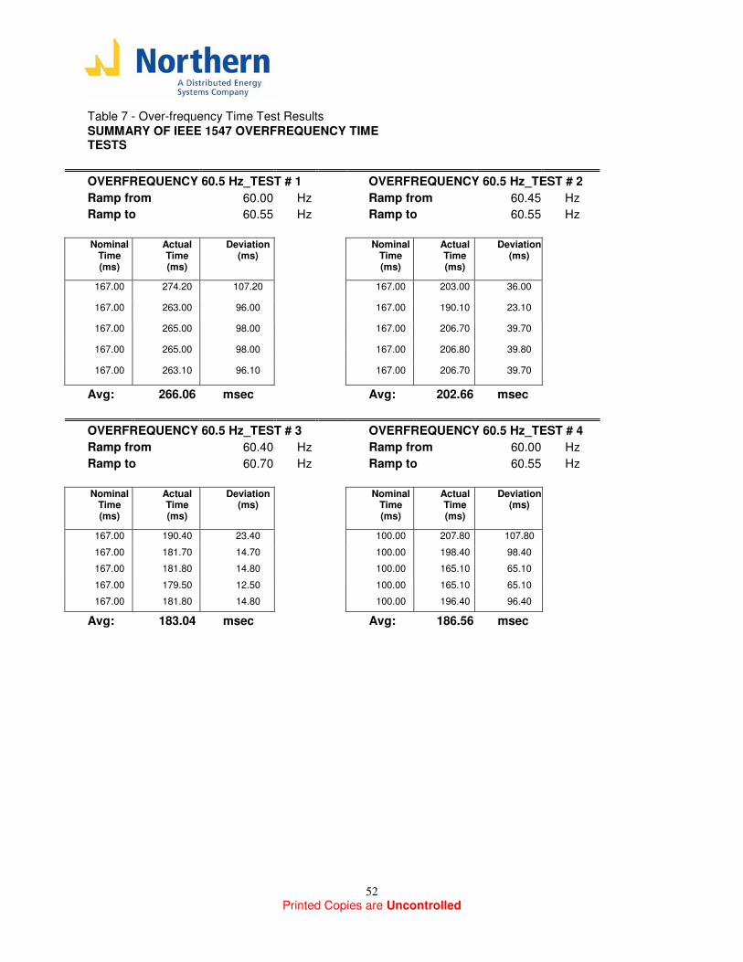
Printed Copies are Uncontrolled
52
Table 7 - Over-frequency Time Test Results
SUMMARY OF IEEE 1547 OVERFREQUENCY TIME TESTS
OVERFREQUENCY 60.5 Hz_TEST # 1 OVERFREQUENCY 60.5 Hz_TEST # 2
Ramp from 60.00 Hz Ramp from 60.45 Hz
Ramp to 60.55 Hz Ramp to 60.55 Hz
Nominal
Time (ms)
Actual Time (ms)
Deviation (ms)
Nominal Time (ms)
Actual Time (ms)
Deviation (ms)
167.00 274.20 107.20
167.00 203.00 36.00
167.00 263.00 96.00
167.00 190.10 23.10
167.00 265.00 98.00
167.00 206.70 39.70
167.00 265.00 98.00
167.00 206.80 39.80
167.00 263.10 96.10
167.00 206.70 39.70
Avg: 266.06 msec Avg: 202.66 msec
OVERFREQUENCY 60.5 Hz_TEST # 3 OVERFREQUENCY 60.5 Hz_TEST # 4
Ramp from 60.40 Hz Ramp from 60.00 Hz
Ramp to 60.70 Hz Ramp to 60.55 Hz
Nominal
Time (ms)
Actual Time (ms)
Deviation (ms)
Nominal Time (ms)
Actual Time (ms)
Deviation (ms)
167.00 190.40 23.40 100.00 207.80 107.80 167.00 181.70 14.70 100.00 198.40 98.40 167.00 181.80 14.80 100.00 165.10 65.10 167.00 179.50 12.50 100.00 165.10 65.10 167.00 181.80 14.80 100.00 196.40 96.40
Avg: 183.04 msec Avg: 186.56 msec
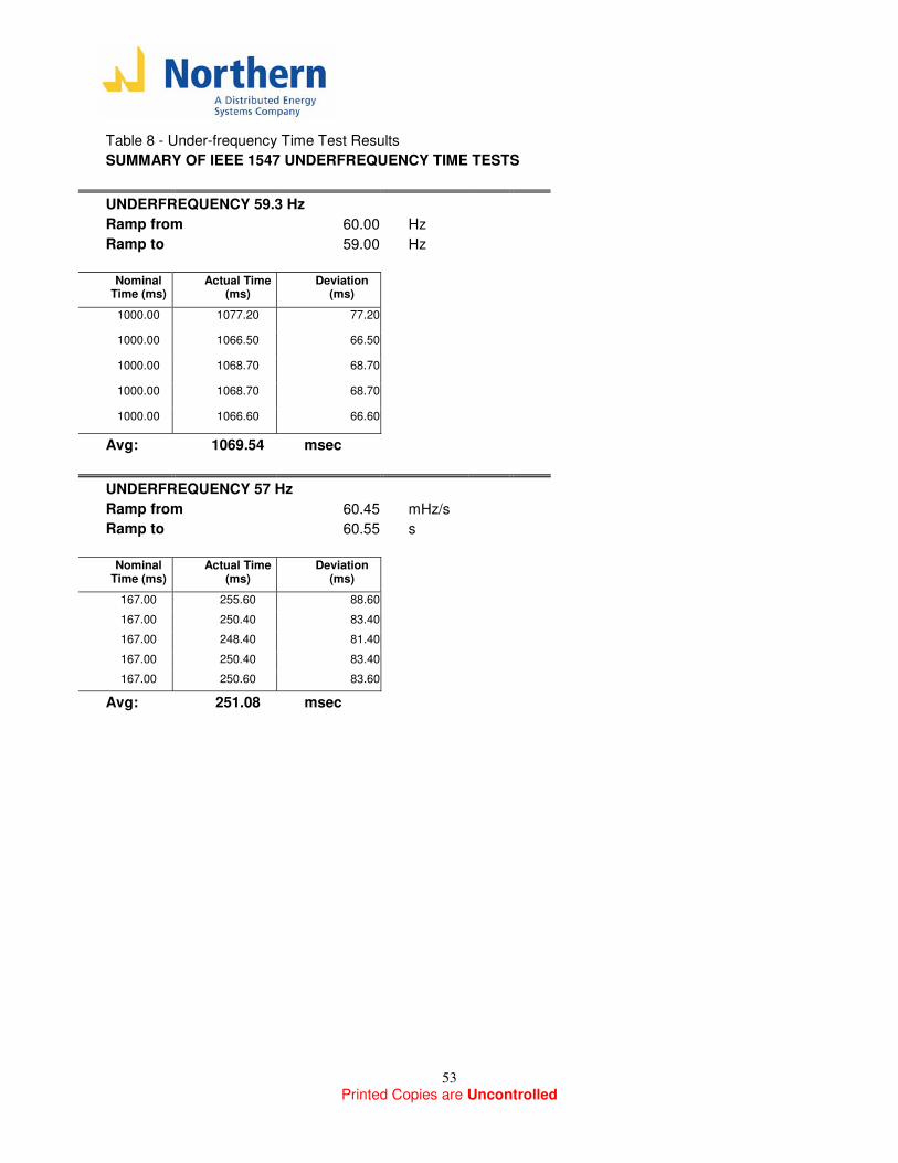
Printed Copies are Uncontrolled
53
Table 8 - Under-frequency Time Test Results
SUMMARY OF IEEE 1547 UNDERFREQUENCY TIME TESTS
UNDERFREQUENCY 59.3 Hz
Ramp from 60.00 Hz
Ramp to 59.00 Hz
Nominal
Time (ms) Actual Time
(ms) Deviation
(ms) 1000.00 1077.20 77.20
1000.00 1066.50 66.50
1000.00 1068.70 68.70
1000.00 1068.70 68.70
1000.00 1066.60 66.60
Avg: 1069.54 msec
UNDERFREQUENCY 57 Hz
Ramp from 60.45 mHz/s
Ramp to 60.55 s
Nominal
Time (ms) Actual Time
(ms) Deviation
(ms) 167.00 255.60 88.60 167.00 250.40 83.40 167.00 248.40 81.40 167.00 250.40 83.40 167.00 250.60 83.60
Avg: 251.08 msec
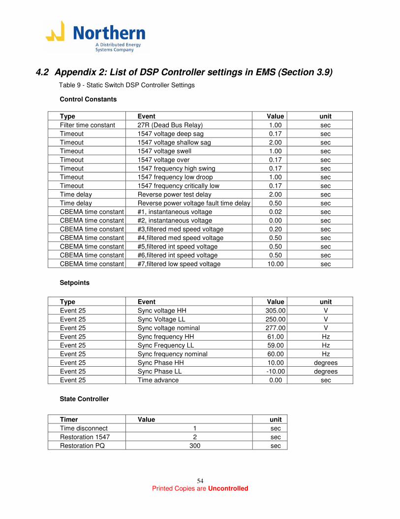
Printed Copies are Uncontrolled
54
4.2 Appendix 2: List of DSP Controller settings in EMS (Section 3.9)
Table 9 - Static Switch DSP Controller Settings
Control Constants
Type Event Value unit
Filter time constant 27R (Dead Bus Relay) 1.00 sec
Timeout 1547 voltage deep sag 0.17 sec
Timeout 1547 voltage shallow sag 2.00 sec
Timeout 1547 voltage swell 1.00 sec
Timeout 1547 voltage over 0.17 sec
Timeout 1547 frequency high swing 0.17 sec
Timeout 1547 frequency low droop 1.00 sec
Timeout 1547 frequency critically low 0.17 sec
Time delay Reverse power test delay 2.00 sec
Time delay Reverse power voltage fault time delay 0.50 sec
CBEMA time constant #1, instantaneous voltage 0.02 sec
CBEMA time constant #2, instantaneous voltage 0.00 sec
CBEMA time constant #3,filtered med speed voltage 0.20 sec
CBEMA time constant #4,filtered med speed voltage 0.50 sec
CBEMA time constant #5,filtered int speed voltage 0.50 sec
CBEMA time constant #6,filtered int speed voltage 0.50 sec
CBEMA time constant #7,filtered low speed voltage 10.00 sec
Setpoints
Type Event Value unit
Event 25 Sync voltage HH 305.00 V
Event 25 Sync Voltage LL 250.00 V
Event 25 Sync voltage nominal 277.00 V
Event 25 Sync frequency HH 61.00 Hz
Event 25 Sync Frequency LL 59.00 Hz
Event 25 Sync frequency nominal 60.00 Hz
Event 25 Sync Phase HH 10.00 degrees
Event 25 Sync Phase LL -10.00 degrees
Event 25 Time advance 0.00 sec
State Controller
Timer Value unit
Time disconnect 1 sec
Restoration 1547 2 sec
Restoration PQ 300 sec
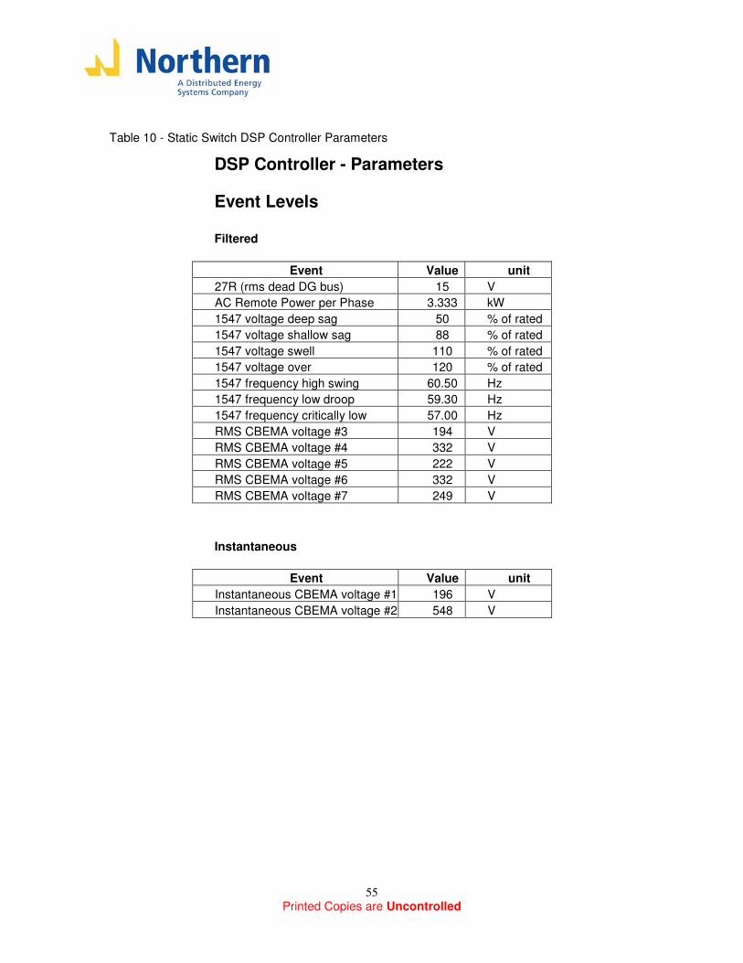
Printed Copies are Uncontrolled
55
Table 10 - Static Switch DSP Controller Parameters
DSP Controller - Parameters
Event Levels
Filtered
Event Value unit
27R (rms dead DG bus) 15 V
AC Remote Power per Phase 3.333 kW
1547 voltage deep sag 50 % of rated
1547 voltage shallow sag 88 % of rated
1547 voltage swell 110 % of rated
1547 voltage over 120 % of rated
1547 frequency high swing 60.50 Hz
1547 frequency low droop 59.30 Hz
1547 frequency critically low 57.00 Hz
RMS CBEMA voltage #3 194 V
RMS CBEMA voltage #4 332 V
RMS CBEMA voltage #5 222 V
RMS CBEMA voltage #6 332 V
RMS CBEMA voltage #7 249 V
Instantaneous
Event Value unit
Instantaneous CBEMA voltage #1 196 V
Instantaneous CBEMA voltage #2 548 V

Printed Copies are Uncontrolled
56
4.3 Appendix 3: Synchronization Tests (Section 3.2) plots
In this appendix, a complete set of waveforms for the synchronization tests that were performed in Section 3.2 is presented. Results in this appendix include all the cases that are described in Table 1 (Section 3.2.3).
The results for each of the 12 tests include three figures:
1) Phase A Voltage Across Switch (Beat Voltage) before closing
2) Response to a “Manual Opening” of the switch
3) Response to a “Synchronized Closing” of the switch
For figures 2) and 3), the following channels represent:
Channel 1: Phase A Switch Current (20 Amps per division)
Channel 2: Phase B Switch Current (20 Amps per division)
Channel 3: Phase C Switch Current (20 Amps per division)
For figures 2) and 3), the vertical arrow in the time axis represents the transition of the switch command from open-to-close or close-to-open (the switch command was used to trigger the oscilloscope plots).