Certification Report of the SmartLine ST 800 HART Pressure ... · SmartLine ST 800 HART Pressure...
24
Certification Report of the SmartLine ST 800 HART Pressure Transmitter Revision No.: 1.0 Date: 2012-Dec-20 Report Number: SEBS-A.091351/12TB Product: SmartLine ST 800 HART Pressure Transmitter Customer: Honeywell International Inc. Honeywell Field Products 512 Virginia, Dr. Fort Washington, PA 19034, USA Order Number: G.SEB.BS.02.006.08.031 Authority: TÜV NORD Systems GmbH & Co. KG Functional Safety Halderstr. 27 86150 Augsburg / Germany Author: Josef Neumann Review: Bianca Pfuff This document is only valid in it’s entirety and separation of any part is not allowed.
Transcript of Certification Report of the SmartLine ST 800 HART Pressure ... · SmartLine ST 800 HART Pressure...

Certification Report
of the
SmartLine ST 800 HART
Pressure Transmitter
Revision No.: 1.0
Date: 2012-Dec-20
Report Number: SEBS-A.091351/12TB
Product: SmartLine ST 800 HART Pressure Transmitter
Customer: Honeywell International Inc.
Honeywell Field Products
512 Virginia, Dr.
Fort Washington, PA 19034, USA
Order Number: G.SEB.BS.02.006.08.031
Authority: TÜV NORD Systems GmbH & Co. KG
Functional Safety
Halderstr. 27
86150 Augsburg / Germany
Author: Josef Neumann
Review: Bianca Pfuff
This document is only valid in it’s entirety and separation of any part is not allowed.

File: SEBS-A.091351_12TB_V1.0_EN_Honeywell_ST800.doc TÜV NORD Systems GmbH & Co. KG Report No.: SEBS-A.091351/12TB Rev.: 1.0 Halderstr. 27 Date: 2012-Dec-20 86150 Augsburg Page 2 of 24
Content Page
1 Subject of certification .................................................................................. 3
2 Basis of certification ...................................................................................... 4
3 Standards ....................................................................................................... 5
4 Definitions ...................................................................................................... 6
5 Overview about the system configuration ................................................... 7
5.1 Primary Safety Functions .................................................................................... 8
5.2 Secondary Safety Functions ............................................................................... 8
5.3 Logic Solver Inputs .............................................................................................. 8
6 Hardware and software identification .......................................................... 9
7 Documentation ............................................................................................... 10
8 Assessment activities and results ............................................................... 15
8.1 Development Process ......................................................................................... 15
8.2 System Architecture ............................................................................................ 18
8.3 Hardware Design and FMEDA ............................................................................ 18
8.4 Software Design and Implementation .................................................................. 21
8.5 Verification and Validation ................................................................................... 22
8.6 Environmental Influences, EMC .......................................................................... 23
8.7 Safety Manual ..................................................................................................... 23
9 Summary ......................................................................................................... 24
History:
Version Date Author Changes
V0.91 2012-12-18 J. Neumann Draft
V1.0 2012-12-20 J. Neumann Final

File: SEBS-A.091351_12TB_V1.0_EN_Honeywell_ST800.doc TÜV NORD Systems GmbH & Co. KG Report No.: SEBS-A.091351/12TB Rev.: 1.0 Halderstr. 27 Date: 2012-Dec-20 86150 Augsburg Page 3 of 24
1 Subject of certification
This report compiles the results of the assessment of the SmartLine ST 800 HART
Pressure Transmitter (thereafter known as SmartLine ST 800) of Honeywell
International Inc. The services of TÜV NORD Systems GmbH & Co. KG (thereafter
known has TÜV NORD Systems) has been ordered by Honeywell International Inc.
to certify the SmartLine ST 800 because of its use in safety-relevant applications by
the process industry (e.g. oil & gas and chemical industry) with the goal of achieving
a successful approval of SmartLine ST 800 in the framework of the certification of
safety-components.
The SmartLine ST 800 is to be certified in accordance with IEC 61508 for single use
in Safety Integrity Level 2 (SIL 2) applications. The development and software
process is to be certified in accordance with SIL 3 requirements allowing the use of
the dual redundant SmartLine ST 800 in SIL 3 applications.

File: SEBS-A.091351_12TB_V1.0_EN_Honeywell_ST800.doc TÜV NORD Systems GmbH & Co. KG Report No.: SEBS-A.091351/12TB Rev.: 1.0 Halderstr. 27 Date: 2012-Dec-20 86150 Augsburg Page 4 of 24
2 Basis of certification
An effective assessment in order to meet all the requirements for a complete
certification requires the following testing segments to be successfully completed:
Functional Safety Management (FSM)
Development process
Architecture
Safety system structure
Hardware design
Software design and implementation
Verification and Validation
Test specification
Including the following principal functional safety considerations:
Hardware failure-behavior
Software failure-avoidance
Probabilistic and Common Cause consideration
Safety Manual

File: SEBS-A.091351_12TB_V1.0_EN_Honeywell_ST800.doc TÜV NORD Systems GmbH & Co. KG Report No.: SEBS-A.091351/12TB Rev.: 1.0 Halderstr. 27 Date: 2012-Dec-20 86150 Augsburg Page 5 of 24
3 Standards
Because of the application area of the SmartLine ST 800, the following standard is
relevant:
Functional Safety
IEC 61508:2010
Ed. 2
Functional safety of electrical/electronic/programmable
electronic safety-related systems
IEC 61508-1 Part 1: General Requirements
General definitions: Type B, Low Demand
IEC 61508-2 Part 2: Requirements for electrical/electronic/programmable
electronic safety-related systems,
Required SIL 2
IEC 61508-3 Part 3: Software requirements
Required SIL 3
File: SEBS-A.091351_12TB_V1.0_EN_Honeywell_ST800.doc TÜV NORD Systems GmbH & Co. KG Report No.: SEBS-A.091351/12TB Rev.: 1.0 Halderstr. 27 Date: 2012-Dec-20 86150 Augsburg Page 6 of 24
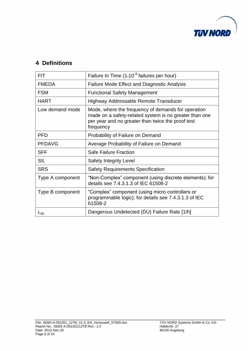
4 Definitions
FIT Failure In Time (1*10-9 failures per hour)
FMEDA Failure Mode Effect and Diagnostic Analysis
FSM Functional Safety Management
HART Highway Addressable Remote Transducer
Low demand mode Mode, where the frequency of demands for operation made on a safety-related system is no greater than one per year and no greater than twice the proof test frequency
PFD Probability of Failure on Demand
PFDAVG Average Probability of Failure on Demand
SFF Safe Failure Fraction
SIL Safety Integrity Level
SRS Safety Requirements Specification
Type A component “Non-Complex” component (using discrete elements); for details see 7.4.3.1.3 of IEC 61508-2
Type B component “Complex” component (using micro controllers or programmable logic); for details see 7.4.3.1.3 of IEC 61508-2
du Dangerous Undetected (DU) Failure Rate [1/h]

File: SEBS-A.091351_12TB_V1.0_EN_Honeywell_ST800.doc TÜV NORD Systems GmbH & Co. KG Report No.: SEBS-A.091351/12TB Rev.: 1.0 Halderstr. 27 Date: 2012-Dec-20 86150 Augsburg Page 7 of 24
5 Overview about the system configuration
The SmartLine ST 800 is a smart device with two-wire 4-20mA HART interface. It
contains self diagnostic and can be programmed to send its output to a specific
failure state, either high or low upon internal detection of a failure. The product has a
modular design with a common sensor board, a HART Communication board and a
Termination board. The SmartLine ST 800 supports an optional local display which is
considered to be non-interfering.
For safety instrumented systems using the HART version it is assumed that the 4-
20mA output is used as the primary safety variable. Although the SmartLine ST 800
series is available with several different output options, no other output variants are
covered by this report.
Figure 1: SmartLine ST 800 Block Diagram
The transmitter can be connected to the process using impulses lines, depending on
the application.

File: SEBS-A.091351_12TB_V1.0_EN_Honeywell_ST800.doc TÜV NORD Systems GmbH & Co. KG Report No.: SEBS-A.091351/12TB Rev.: 1.0 Halderstr. 27 Date: 2012-Dec-20 86150 Augsburg Page 8 of 24
5.1 Primary Safety Functions
The HONEYWELL SmartLine ST 800 measures the (pressure gauge, differential,
absolute) of a process and reports the measurement within a safety accuracy of 2%.
5.2 Secondary Safety Functions
The HONEYWELL SmartLine ST 800 performs automatic diagnostics to detect
internal failures and reports these failures via out of band signals on the 4 – 20 mA
output. The transmitter needs a power cycle for recovery from this condition.
5.3 Logic Solver Inputs
The logic solver must be configured so that the engineering range in the transmitter
matches the expected range of the logic solver.
To take advantage of the internal diagnostics in the SmartLine ST 800, the logic
solver must be configured to annunciate an out of band current reading (greater than
20.8 mA. or less than 3.8 mA.) in standard instrument or (greater than 21.0 mA. or
less than 3.6 mA.) with Namur option as a diagnostic fault. The logic solver
configuration must consider the slew time of the current signal and ensure that
filtering is used to prevent a false diagnostic failure annunciation.

File: SEBS-A.091351_12TB_V1.0_EN_Honeywell_ST800.doc TÜV NORD Systems GmbH & Co. KG Report No.: SEBS-A.091351/12TB Rev.: 1.0 Halderstr. 27 Date: 2012-Dec-20 86150 Augsburg Page 9 of 24
6 Hardware and software identification
The following versions are considered for the certification:
Hardware:
Sensor Assy 50053143 – Rev C
HART/DE Comm Assy 50050919 – Rev C
HART/DE TB Assy 500055716 – Rev C
Software/Firmware:
Sensor board: v1.000000
Comm board: v1.020000

File: SEBS-A.091351_12TB_V1.0_EN_Honeywell_ST800.doc TÜV NORD Systems GmbH & Co. KG Report No.: SEBS-A.091351/12TB Rev.: 1.0 Halderstr. 27 Date: 2012-Dec-20 86150 Augsburg Page 10 of 24
7 Documentation
The evaluation is based on the following documents of the SmartLine ST 800:
[D1] PAR Tracking User Guide
[D2] Management Review Process
[D3] Program Management Plan
[D4] HPS Global Quality Manual
[D5] ISO 9000 Certificate
[D6] Customer Notification Process
[D7] Quality Link proactive field action message
[D8] Return Goods Authorization (RGA) Procedure
[D9] Coding Standards for Embedded C
[D10] HPS GTS Escalation Process
[D11] Part Qualification Procedure
[D12] Manufacturing Qualification Procedure
[D13] Non-Conforming Reporting Procedure
[D14] Corrective Action Procedure
[D15] Corrective Action Procedure Aux
[D16] Test Equipment Master Cal List
[D17] GTS Escalation Flow
[D18] ST6000 r100 Functional Safety Management Plan
[D19] SIL Overview slides
[D20] exida Configuration Management Checklist
[D21] exida Documentation Checklist
[D22] exida Software Tool Checklist
[D23] exida Tool Validation Checklists
[D24] Configuration and Change Management Plan
[D25] HPS Technology Backup Policy
[D26] HFS New Product Development & Introduction Process
[D27] New Product Development Functional Process map

File: SEBS-A.091351_12TB_V1.0_EN_Honeywell_ST800.doc TÜV NORD Systems GmbH & Co. KG Report No.: SEBS-A.091351/12TB Rev.: 1.0 Halderstr. 27 Date: 2012-Dec-20 86150 Augsburg Page 11 of 24
[D28] PWA Design Process Map
[D29] Team Competency Summary
[D30] HIP process overview
[D31] NPI Stage Gate Review Checklist
[D32] Solutions Council Review example
[D33] NPI Stage Gate Review Support
[D34] IEC 61508 Assessment Action Item List
[D35] PROGRAMMABLE DEVICE (PD) PROCESS Flowchart
[D36] exida FSM Planning Phase Verification Checklist
[D37] ST 800 SIL Requirements
[D38] exida SRS Document Checklist
[D39] Marketing Requirements Document
[D40] Product Requirements Specification Document
[D41] ST800 Solution Requirements Spec
[D42] Safety Validation Test Plan
[D43] SIL Requirements Traceability
[D44] System Test plan review
[D45] exida Safety Validation Test Plan Checklist
[D46] HART SW System Test Plan
[D47] HART SW System Test Cases
[D48] Typhoon Test plan- high level definition phase
[D49] ST 6000 Foundation Fieldbus/PROFIBUS-PA Communication Board
Hardware Maintenance Document
[D50] ST6000 HART-DE Communication Board Hardware Maintenance Doc.
[D51] Typhoon protocol to exchange data between the various Typhoon PWAs
[D52] TYPHOON TERMINAL BLOCK MODULE DESIGN REVIEW
[D53] InterProcessor Communication Protocol Review
[D54] exida Integration Test Plan Checklist
[D55] Architecture and Development Process Review
[D56] TYPHOON Pressure Transmitter SIL Review

File: SEBS-A.091351_12TB_V1.0_EN_Honeywell_ST800.doc TÜV NORD Systems GmbH & Co. KG Report No.: SEBS-A.091351/12TB Rev.: 1.0 Halderstr. 27 Date: 2012-Dec-20 86150 Augsburg Page 12 of 24
[D57] ST 6000 CM360 Pressure Sensor Board Hardware Maintenance
Document
[D58] Schematics - combined files
[D59] exida Fault Injection Checklist
[D60] exida HW Fault Injection Test Verification Checklist
[D61] BOM - combined files
[D62] De-rating Analysis
[D63] QA Reliability Plan
[D64] Fault Injection Test Plan
[D65] ST6000 Terminal Block Hardware Maintenance Document
[D66] ST800 HART Terminal Board test results
[D67] ST800 HART HW test plan and results
[D68] ST800 Sensor HW unit test plan
[D69] ST800 HART HW architecture
[D70] ST800 Sensor HW architecture
[D71] ST800 Terminal Board HW architecture
[D72] ST800 Term Bd test plan
[D73] exida Hardware Development Phase Verification Checklist
[D74] ST 6000 Sensor Firmware Maintenance Document
[D75] Typhoon ST6000 (Foundation Fieldbus) Comm SW Maint Doc
[D76] ST6000 Smart Meter Software Maintenance Document
[D77] ST 6000 HART-DE Communication Board SW Maint Doc
[D78] ST800 Sensor SW Criticality Analysis
[D79] ST800 HART SW Criticality Analysis
[D80] ST800 HART stack and interrupt design
[D81] ST800 HART design review
[D82] ST800 SW architecture for HART board- HLD
[D83] ST800 Software architecture for sensor board- HLD
[D84] exida Software Architecture and Design Phase Checklist
[D85] IEC 61508 SIL3 Tables not covered in FSM Plan
[D86] Tools Evaluation and Justification

File: SEBS-A.091351_12TB_V1.0_EN_Honeywell_ST800.doc TÜV NORD Systems GmbH & Co. KG Report No.: SEBS-A.091351/12TB Rev.: 1.0 Halderstr. 27 Date: 2012-Dec-20 86150 Augsburg Page 13 of 24
[D87] ClearCase Issue Resolutions
[D88] Tool Justification Report
[D89] Test Witnessing - HART board
[D90] Test Witnessing - Sensor board
[D91] Example of Field Issues for testing
[D92] Sensor Complexity Metric and Criticality Analysis
[D93] PC Lint Support - sensor
[D94] PC Lint Support - HART board
[D95] Unit Test Records - sensor
[D96] ST800 automated sensor regression test script results
[D97] ST800 sensor automated system testsets
[D98] boundary & equivalence class test examples
[D99] Module ST6KMeasure.c test support for D92b
[D100] Automated test design for HART
[D101] Automated test scripts for HART
[D102] Automated test results for HART
[D103] Code Review example - HART
[D104] Code Review example - Sensor
[D105] Code Review example - data hiding
[D106] ST800 Sensor Unit Test Plan (big file)
[D107] ST800 Sensor Unit Test Plan (part 2)
[D108] ST800 HART board Unit Test Plan for SIL
[D109] ST800 HART board Unit Test Cases and Results for SIL
[D110] ST800 HART unit test, non-SIL, pt1
[D111] ST800 HART unit test, non-SIL, pt2
[D112] ST800 HART unit test results
[D113] exida SW Implementation Phase Verification Checklist
[D114] exida Integration Test Execution Phase Checklist
[D115] EMC Test Results
[D116] Smart Pressure Transmitter Environmental Test Plan.
[D117] Validation Test Results (Performance)

File: SEBS-A.091351_12TB_V1.0_EN_Honeywell_ST800.doc TÜV NORD Systems GmbH & Co. KG Report No.: SEBS-A.091351/12TB Rev.: 1.0 Halderstr. 27 Date: 2012-Dec-20 86150 Augsburg Page 14 of 24
[D118] Performance Validation Test Results (meterbody file)
[D119] Fault Injection Test Results
[D120] FIT witnessing
[D121] ST800 HART sw system test results
[D122] ST800 HART HW Phys Layer test results
[D123] HART system test results (updated)
[D124] HART system test evaluation
[D125] Sensor system test set summary
[D126] exida Functional Safety Assessment Phase Verification Checklist
[D127] Functional Safety Assessment Plan - FSA Plan
[D128] ST800 Safety Manual
[D129] Safety Manual review
[D130] Proof test verification
[D131] ST800 HART SW Release Construction
[D132] ST800 User Manual
[D133] SHA-1 Hash Signature- Sensor
[D134] SHA-1 Hash Signature- HART
[D135] Failure Modes, Effects and Diagnostics Analysis (FMEDA) Report
[D136] exida FMEDA Document Checklist
[D137] Change Control Process
[D138] HW/Elec Change Process Map
[D139] PAR Change Report summary
[D140] HON Safety Impact Analysis Form
[D141] exida Modification Phase Verification Checklist
Documentation from the Auditor:
[D142] SEBS-A 20120518.091351_V1 0Quot_Honeywell_ST800.pdf
[D143] Fault Injection Tests ST800 Pressure Transmitter V1.0
[D144] TUVNORD_review_FMEDA_ST800_V3.0.doc
[D145] TUVNORD_Review_Honeywell_ST800_v0.1.doc
[D146] CL_IEC61508_V1_0_Honeywell_ST800_V1.0

File: SEBS-A.091351_12TB_V1.0_EN_Honeywell_ST800.doc TÜV NORD Systems GmbH & Co. KG Report No.: SEBS-A.091351/12TB Rev.: 1.0 Halderstr. 27 Date: 2012-Dec-20 86150 Augsburg Page 15 of 24
8 Assessment activities and results
8.1 Development Process
General aspects and scope:
In this step of assessment, a safety management audit has been performed to cover
the relevant requirements of the IEC 61508, in respect of the fulfillment of the
requirements to the safety quality procedures.
The scope of the Functional Safety Management Audit covers the specified Safety
Lifecycle Phases of the IEC 61508. The scope for Honeywell International Inc. is as
follows:
For design, developing, manufacturing and integration
of microprocessor based transmitters.
For the Functional Safety Management Audit according to IEC 61508 it was essential
that the functional safety management and the software development process are
designed for the SIL 3 level to allow the set up of a redundant SmartLine ST 800
system in a SIL 3 environment. The FSM procedures are used to reduce the
systematic failure rate. Honeywell International Inc. has created the following
documents to define the FSM activities:
HPS Global Quality Manual [D4]
Program Management Plan [D3]
Functional Safety Management Plan [D18]
PWA Design Process Map [D28]
HFS New Product Development & Introduction Process [D26]
Configuration and Change Management Plan [D24]
HIP process overview [D30]
Within the project all safety relevant definitions are defined by the Functional Safety
Management and the normative requirements.

File: SEBS-A.091351_12TB_V1.0_EN_Honeywell_ST800.doc TÜV NORD Systems GmbH & Co. KG Report No.: SEBS-A.091351/12TB Rev.: 1.0 Halderstr. 27 Date: 2012-Dec-20 86150 Augsburg Page 16 of 24
Structuring of the development process
The documents [D1] to [D36] describe the Honeywell International Inc. development
processes, procedures and work-instructions. TÜV NORD Systems visited the
Honeywell International Inc. development site as an external assessment
department, toured the facilities and interviewed the Safety Design Team in order to
understand all the relevant corporate procedures. They then extracted the most
important functional safety management requirements from the standards and
prepared documents indicating needed enhancements of the standard processes.
TÜV NORD Systems has reviewed this document to discuss the overall FSM
requirement activities for the project with Honeywell International Inc. TÜV NORD
Systems has than discussed the relevant items with Honeywell International Inc. and
reviewed the documents for the safety aspects of the system. Honeywell
International Inc. is covering the following areas:
Functional Safety Management
Quality Management System
Development of Safety Sub-Systems (Realization)
Verification & Validation activities (Testing)
The focus of the interview with Honeywell International Inc. was to demonstrate
compliance with the appropriate sections of the IEC 61508 standard. The following
sections were considered:
Specific Objectives for Functional Safety
Change Management (Modification Process)
Maintenance
The reviews with Honeywell International Inc. were related to the following areas:
Safety Requirement specification
Safety Architectural Constrains

File: SEBS-A.091351_12TB_V1.0_EN_Honeywell_ST800.doc TÜV NORD Systems GmbH & Co. KG Report No.: SEBS-A.091351/12TB Rev.: 1.0 Halderstr. 27 Date: 2012-Dec-20 86150 Augsburg Page 17 of 24
Safety Hardware Requirements
Safety Software Requirements
Verification & Validation of Safety Products
Safety Manual
It was essential for the audit to discuss the safety aspects of the project with the
participants and to ask for the relevant documents and to access all relevant
information. Actual documentation from the SmartLine ST 800 project was partly
reviewed and the statements of the participants were compared with the relevant
parts of the documents.
Verification & Validation activities (Testing)
For verification & validation the independent test engineers are responsible for all
activities within this segment. The definitions out of the tables of the standard are
defined in [D85] to [D92]. They create the test specifications for specific projects used
by the development engineers. The functional tests and integration and validation
testing was done by independent test engineers. The test engineers must have
specific knowledge about safety functions of the specific project. Internal training is
therefore an important method to improve the knowledge of the test engineers. This
could be proved by interviews and with reviews of examples of the corresponding
documents.
Result
The document reviews have shown that the Functional Safety Management System,
defined in the documents [D1] to [D36] complies with the applicable sections of the
IEC 61508.
No major findings were detected in the audit.
If changes to the Safety Management Systems are performed than TÜV NORD
Systems must be informed.

File: SEBS-A.091351_12TB_V1.0_EN_Honeywell_ST800.doc TÜV NORD Systems GmbH & Co. KG Report No.: SEBS-A.091351/12TB Rev.: 1.0 Halderstr. 27 Date: 2012-Dec-20 86150 Augsburg Page 18 of 24
8.2 System Architecture
The system documents [D37] to [D48] have been reviewed to verify compliance of
the system architecture with the standard listed in clause 3 "Standards".
Based on the set of requirements TÜV NORD Systems has evaluated whether the
implemented fault detection and fault control measures which are defined for the
SmartLine ST 800 were sufficient to meet the requirements. The system architecture
was evaluated in regards to completeness and correctness against the hardware and
software requirements specification [D37]. The system architecture have to be
designed for a Type B subsystem according the IEC 61508-2 with a Safe Failure
Fraction of 90% or higher.
The FMEDA verified the defined safe state of the SmartLine ST 800 in the event of
possible malfunctions. Probable deviation from the specified function of the unit was
also considered to be a malfunction.
Result
The review from TÜV NORD Systems has shown that the system architecture of the
SmartLine ST 800 is consistent against the Safety Requirements Specification. The
specifications in the documentation are consistent and complete and clearly
presented. The system concept with the chosen architecture design and the selected
measures of fault detection and fault control is able to fulfill the Safety Integrity Level
2 with a Safe Failure Fraction of >90%.
8.3 Hardware Design and FMEDA
A Failure Modes and Effects Analysis (FMEA) is a systematic way to identify and
evaluate the effects of different component failure modes, to determine what could
eliminate or reduce the chance of failure, and to document the system in
consideration.
A FMEDA (Failure Mode Effect and Diagnostic Analysis) is an extension of the
FMEA. It combines standard FMEA techniques with additional analysis to identify
online diagnostic techniques and the failure modes relevant to safety system design.
It is a technique recommended to generate failure rates for each important category

File: SEBS-A.091351_12TB_V1.0_EN_Honeywell_ST800.doc TÜV NORD Systems GmbH & Co. KG Report No.: SEBS-A.091351/12TB Rev.: 1.0 Halderstr. 27 Date: 2012-Dec-20 86150 Augsburg Page 19 of 24
(detected, dangerous undetected, fail high, fail low, annunciation) in the safety
model.
The following assumptions have been made during the Failure Modes, Effects, and
Diagnostic Analysis of the SmartLine ST 800:
• Only a single component failure will fail the entire SmartLine ST 800
• Failure rates are constant, wear-out mechanisms are not included
• Propagation of failures is not relevant
• All components that are not part of the safety function and cannot influence
the safety function (feedback immune) are excluded
• The stress levels are average for an industrial environment and can be
compared to the exida Profile 2 with temperature limits within the
manufacturer’s rating. Other environmental characteristics are assumed to be
within manufacturer’s rating.
• Practical fault insertion tests can demonstrate the correctness of the failure
effects assumed during the FMEDA and the diagnostic coverage provided by
the online diagnostics
• The HART protocol is only used for setup, calibration, and diagnostics
purposes, not for safety critical operation.
• The application program in the logic solver is constructed in such a way that
Fail High and Fail Low failures are detected regardless of the effect, safe or
dangerous, on the safety function.
• Materials are compatible with process conditions
• The device is installed per manufacturer’s instructions
• The Transmitter is generally applied in relatively clean gas or liquid, therefore
no severe service has been considered in the analysis of the base
Transmitter.
• External power supply failure rates are not included
• Worst-case internal fault detection time is 9 minutes

File: SEBS-A.091351_12TB_V1.0_EN_Honeywell_ST800.doc TÜV NORD Systems GmbH & Co. KG Report No.: SEBS-A.091351/12TB Rev.: 1.0 Halderstr. 27 Date: 2012-Dec-20 86150 Augsburg Page 20 of 24
The following tables show the failure rates resulted from the SmartLine ST 800
FMEDA [D135].
Table 1 and Table 2 list the failure rates for the SmartLine ST 800. These failure
rates do not include failure of the sensing devices.
Failure category Failure rate (in FIT)
Fail Safe Undetected 174.3
Fail Dangerous Detected 222.7
- Fail Detected (detected by internal diagnostics) 153.3
- Fail High (detected by the logic solver) 26.7
- Fail Low (detected by the logic solver) 42.8
Fail Dangerous Undetected 43.9
No Effect 102.4
Annunciation Undetected 1.4
External Leakage 22.5
Table 1 Failure rates SmartLine ST 800
The failure rates that are derived from the FMEDA for the SmartLine ST 800 are in a
format different from the IEC 61508 format. Table 2 lists the failure rates for
SmartLine ST 800 according to IEC 61508, assuming that the logic solver can detect
both over-scale and under-scale currents.
It is assumed that the probability model will correctly account for the Annunciation
Undetected failures. Otherwise the Annunciation Undetected failures have to be
classified as Dangerous Undetected according to IEC 61508 (worst-case
assumption). The No Effect and Annunciation Undetected failures are classified as
safe and therefore need to be considered in the Safe Failure Fraction calculation and
are included in the total failure rate.
According to IEC 61508, also the Safe Failure Fraction (SFF) of the SmartLine ST
800 should be calculated. The SFF is the fraction of the overall failure rate of a
device that results in either a safe fault or a diagnosed unsafe fault. This is reflected
in the following formula for SFF:
SFF = 1 - ּגdu / ּגtotal
Where ּגtotal = ּגsd + ּגsu+ ּגdd+ ּגdu

File: SEBS-A.091351_12TB_V1.0_EN_Honeywell_ST800.doc TÜV NORD Systems GmbH & Co. KG Report No.: SEBS-A.091351/12TB Rev.: 1.0 Halderstr. 27 Date: 2012-Dec-20 86150 Augsburg Page 21 of 24
Device ּגsd ּגsu ּגdd ּגdu SFF
SmartLine ST 800 with 4-20mA 0 FIT 174.3 FIT 222.7 FIT 43.9 FIT 90.0%
Table 2: Failure rates and Safe Failure Fraction according to IEC 61508
The architectural constraint type for the SmartLine ST 800 is B. The SFF and
required SIL determine the level of hardware fault tolerance that is required per
requirements of IEC 61508. The SIS designer is responsible for meeting other
requirements of applicable standards for any given SIL as well.
The expected lifetime of the Honeywell International Inc. SmartLine ST 800 is 50
years. The failure rates of the Honeywell International Inc. SmartLine ST 800 may
increase sometime after this period.
When plant experience indicates a shorter useful lifetime, the number based on plant
experience should be used.
Result:
With these results from the calculation it can be shown, that the SmartLine ST 800
fulfils SIL 2 for the hardware design in a single configuration.
8.4 Software Design and Implementation
The software design is defined in the software design documents [D74] to [D84]. To
provide the necessary internal testing of the hardware module to cover the IEC
61508 requirements for the Safe Failure Fraction (SFF) according SIL 2 various
diagnostics has been implemented. This was done following the IEC 61508-3 SIL 3
process for software developing and implementation. These additional tests includes
RAM and ROM testing and a flow control to reach a sufficient safe failure fraction >
90%. Coding standards are defined [D9] and tested in [D93] and [D94]. The
corresponding documents have been reviewed by TÜV NORD Systems.

File: SEBS-A.091351_12TB_V1.0_EN_Honeywell_ST800.doc TÜV NORD Systems GmbH & Co. KG Report No.: SEBS-A.091351/12TB Rev.: 1.0 Halderstr. 27 Date: 2012-Dec-20 86150 Augsburg Page 22 of 24
Result
The normative requirements out of the techniques and measures according to the
IEC 61508-3 for software have been selected in the high level design of the software
[D83]and considered for the development of the software. The software design and
implementation and implemented measures are compliant to IEC 61508 part 3
according SIL 3.
8.5 Verification and Validation
The verification activities are defined by the reviews of the documentation according
the specific phases of the development model (V-model). The review documentation
has been discussed with responsible engineers from Honeywell International Inc. and
has been reviewed by TÜV NORD Systems.
The test specification defined in the System Test Documentation [D85] to [D92] from
the manufacturer has been reviewed. The list of validation tests are referenced to the
Requirement Specification. The review has shown that the requirements are covered
by the validation plan.
After the execution of the validation tests by the manufacturer [D117], the test results
have been reviewed by TÜV NORD Systems. The test results are also referenced to
the Design Specification.
The definition and results are documented in the Fault Injection Test Reports [D119].
In addition of the Fault Injection Tests from the manufacturer example Tests have
been performed by TÜV NORD Systems together with the test team. The results are
documented in [D143]
Result
The review of the Integration Test Plan and the Test Reports from the manufacturer
and the execution of the sample tests by TÜV NORD Systems have shown that the
defined tests are consistent to the Design Specification and the tested results can be
compared to the tests of the manufacturer. The test definitions are sufficient to prove
compliance with the standard.

File: SEBS-A.091351_12TB_V1.0_EN_Honeywell_ST800.doc TÜV NORD Systems GmbH & Co. KG Report No.: SEBS-A.091351/12TB Rev.: 1.0 Halderstr. 27 Date: 2012-Dec-20 86150 Augsburg Page 23 of 24
8.6 Environmental Influences, EMC
The tests related to the environmental influences and EMC have been carried out
through Honeywell International Inc. to show that the functional safety is not affected.
The test plan and test results for the SmartLine ST 800 environmental and EMC tests
are documented in [D115] and [D116].
Result
The defined requirements with respect to environmental influences and EMC are
met. The tests carried out did not give rise to any safety objections.
8.7 Safety Manual
The Safety Manual [D128] has been reviewed to fulfill the requirements of the
considered standard. Specifically the section about Proof Testing has been checked
according the defined measures to be followed up by the end user to be compliant
with the considered standard according failure detection which are not covered by
the diagnostic of the transmitter.
Result
The review has shown that the Safety Manual meets the requirement of the
considered standard. Detailed descriptions are included for the end user to install,
operate and maintain the transmitter in the required safety level.

File: SEBS-A.091351_12TB_V1.0_EN_Honeywell_ST800.doc TÜV NORD Systems GmbH & Co. KG Report No.: SEBS-A.091351/12TB Rev.: 1.0 Halderstr. 27 Date: 2012-Dec-20 86150 Augsburg Page 24 of 24
9 Summary
The assessment of the SmartLine ST 800 has shown that the system design, the
safety functional management and the system structure are compliant with the IEC
61508, SIL 2 under consideration of the proven in use of the transmitter and the
additional measures implemented to the transmitter. The defined development
process of the software is in accordance with SIL 3 requirements allowing the use of
dual redundant SmartLine ST 800 in SIL 3 applications.
The validation and testing activities has shown compliances between the realized
transmitter implementation and the safety requirements specification.
The actual version of the Safety Manual must be considered for the use in safety
relevant applications.