Certificate of Compliance for the Holtec HI-STAR 100 (MPC-24 ...
67
NRC FORM 651 U.S. NUCLEAR REGULATORY COMMISSION I(3-1999) 10 CFR 72 CERTIFICATE OF COMPLIANCE FOR SPENT FUEL STORAGE CASKS Page 1 of 3 The U.S. Nuclear Regulatory Commission is Issuing this Certificate of Compliance pursuant to Title 10 of the Code of Federal Regulations, Part 72, Licensing Requirements for Independent Storage of Spent Nuclear Fuel and High-Level Radioactive Waste' (10 CFR Part 72). This certificate is issued In accordance with 10 CFR 72.238, certifying that the storage design and contents described below meet the applicable safety standards set forth in 10 CFR Part 72, Subpart L, and on the basis of the Final Safety Analysis Report (FSAR) of the cask design. This certificate Is conditional upon fulfilling the requirements of 10 CFR Part 72, as applicable, and the conditions specified below. Certificate No. Effective Date Expiration Date Docket Number Amendment No. Amendment Date Package Identification No. 1008 1014/1999 10/4/2019 72-1008 USA/72-1008 Issued To: (Name/Address) Holtec International Holtec Center 555 Lincoln Drive West Marlton, NJ 08053 p . *j . : -'.. Safety Analysis Report Title Holtec International Inc., Safety Analysis Report for the HI-STAR 100 Cask System, Revision 10 Holtec Report H-941184 Docket No.72-1008 - 'JDITIONS S " ' .s - - 1. CASK X ~ The HI-STAR 100 Cask System is cErifidas described in the Safety Analysis Report (SAR) and in NRC's Safety Evaluiation Report (SER) accompanying th'e Certificate of Compliance. It is designed for both storage and transfer of irradiated nuclea rfuel.' ; a. Model No.: HI-STAR 100'(MPC-24, MPC-68, MPC-68F); The HI-STAR 100 Cask System is comprised of the multi-purpose'canister (MPC), which contains the fuel, andthe overpack which contains the MPC" The two digits after the MPC designate the number of reactor fuel assemblies for which therespective MPCs are designed. The MPC-24 is designed to contain up to 24 pressurized water reactor (PWR) fuel assemblies. The MPC-68 is designed to contain'up to 68 boiling water reactor (BWR) fuel assemblies. Any MPC-68 containing fuel assemblies with known or suspected defects, such as ruptured fuel rods, severed rods, loose fuel pellets, or.which cannot be handled by normal means due to fuel cladding damage, is designated as MPC-68F. The MPC-24 and the MPC- 68 (including the MPC-68F) are identical in external dimensions and will fit into the same overpack design. PDR ADOCK 07201008 B PDR
-
Upload
nguyenhanh -
Category
Documents
-
view
226 -
download
2
Transcript of Certificate of Compliance for the Holtec HI-STAR 100 (MPC-24 ...
NRC FORM 651 U.S. NUCLEAR REGULATORY COMMISSIONI(3-1999)10 CFR 72 CERTIFICATE OF COMPLIANCE
FOR SPENT FUEL STORAGE CASKS Page 1 of 3
The U.S. Nuclear Regulatory Commission is Issuing this Certificate of Compliance pursuant to Title 10 of the Code of Federal Regulations,Part 72, Licensing Requirements for Independent Storage of Spent Nuclear Fuel and High-Level Radioactive Waste' (10 CFR Part 72).This certificate is issued In accordance with 10 CFR 72.238, certifying that the storage design and contents described below meet theapplicable safety standards set forth in 10 CFR Part 72, Subpart L, and on the basis of the Final Safety Analysis Report (FSAR) of the caskdesign. This certificate Is conditional upon fulfilling the requirements of 10 CFR Part 72, as applicable, and the conditions specified below.
Certificate No. Effective Date Expiration Date Docket Number Amendment No. Amendment Date Package Identification No.
1008 1014/1999 10/4/2019 72-1008 USA/72-1008Issued To: (Name/Address)
Holtec InternationalHoltec Center555 Lincoln Drive WestMarlton, NJ 08053 p . *j .: -'..
Safety Analysis Report Title
Holtec International Inc., Safety Analysis Report for the HI-STAR 100 Cask System, Revision 10Holtec Report H-941184
Docket No.72-1008 -'JDITIONS S " ' .s - -
1. CASK X ~
The HI-STAR 100 Cask System is cErifidas described in the Safety Analysis Report (SAR) and inNRC's Safety Evaluiation Report (SER) accompanying th'e Certificate of Compliance. It is designedfor both storage and transfer of irradiated nuclea rfuel.' ;
a. Model No.: HI-STAR 100'(MPC-24, MPC-68, MPC-68F);
The HI-STAR 100 Cask System is comprised of the multi-purpose'canister (MPC), whichcontains the fuel, andthe overpack which contains the MPC" The two digits after the MPCdesignate the number of reactor fuel assemblies for which therespective MPCs aredesigned. The MPC-24 is designed to contain up to 24 pressurized water reactor (PWR) fuelassemblies. The MPC-68 is designed to contain'up to 68 boiling water reactor (BWR) fuelassemblies. Any MPC-68 containing fuel assemblies with known or suspected defects, suchas ruptured fuel rods, severed rods, loose fuel pellets, or.which cannot be handled by normalmeans due to fuel cladding damage, is designated as MPC-68F. The MPC-24 and the MPC-68 (including the MPC-68F) are identical in external dimensions and will fit into the sameoverpack design.
PDR ADOCK 07201008B PDR
NRC FORM 651A U.S. NUCLEAR REGULATORY COMMISSION(31999) 10CFR72 CERTIFICATE OF COMPLIANCE Certificate No. 1008
FOR SPENT FUEL STORAGE CASKSSupplemental Sheet Page 2 of 3
b. Description
The complete HI-STAR 100 Cask System for storage of spent nuclear fuel is comprised oftwo discrete components: the MPC and the storage/transport overpack. The HI-STAR 100Cask System consists of interchangeable MPCs which constitute the confinement boundaryfor BWR or PWR spent nuclear fuel and an overpack which provides the helium retentionboundary, gamma and neutron radiation shielding, and heat rejection capability. All MPCshave identical exterior dimensions which render them interchangeable. A single overpackdesign is provided which is capable of storing each type of MPC.
The HI-STAR 100 MPCs are welded cylindrical structures with flat ends. Each MPC is anassembly consisting of a honeycombed fuel basket, a baseplate, canister shell, a lid, and aclosure ring. The outer diametefand cylindrical height of each MPC is fixed. However, thenumber of spent nuclear fuel 'storage locations in each of the MPCs depends on the fuelassembly characteristics: 'The MPC provides the confinement boundary for the stored fuel.The confinement boundary is a seal-welded enclosure constructed entirely of a stainlesssteel alloy. The nnr surfaces of the HI-STAR 100 overpack form in internal cylindricalcavity for housing the MPC. The outer surface of the overpack iiiner'shell is buttressed withintermediate shells ofgamma shielding.
The fuel transfer and a ipmssar pendent Spent Fuel StorageITalfulto oeainaentnIu ry for InepnntpntFlSorgInstallation operation are not'incl a's f the H-STAR 100 Cask System reviewed fora Certificat .of Complian &der40 CFR Part 72, Subpart L. Such equipment may include,but is not inmited to, special ifting devics,' transfer trailers or equipment, and vacuumdrying/he 06iml leak te'st dquipfienUt.-q
2. OPERATING P
Written operating procedures shall be prepared for cask handling; loading, movement, surveillance,and maintenance. The user's site-spcific writtenoperating procedures shall be consistent with thetechnical basis described in the SAR.
3. QUALITY ASSURANCE A
Activities in the areas of design, procurement; fabricatiorr, assembly, inspection, testing, operation,maintenance, repair, modification of structures, .systerm's and components, and decommissioningthat are important to safety shall be conducted in accordance with a Commission-approved qualityassurance program which satisfies the applicable requirements of 10 CFR Part 72, Subpart G, andwhich is established, maintained, and executed with regard to the cask system.
IL I
* NRC FORM 651A U.S. NUCLEAR REGULATORY COMMISSION(3-1999)
l 10CFR 72 CERTIFICATE OF COMPLIANCE Certificate No. 1008FOR SPENT FUEL STORAGE CASKS
Supplemental Sheet Page 3 of 3L
4. HEAVY LOADS REQUIREMENTS
Each lift of a HI-STAR 100 spent fuel storage cask must be made in accordance with the existingheavy loads requirements and procedures of the licensed facility in which the lift is made. A plant-specific safety review (in accordance with 10 CFR 50.59 or 10 CFR 72.48, if applicable) is requiredto show operational compliance with existing plant-specific heavy loads requirements.
5. APPROVED CONTENTS
Contents of the HI-STAR 100 Cask System must meet the fuel specifications given in Appendix B tothis certificate.
6. APPROVED DESIGN FEATURES .. ' .
Features or characteristics for the site or cask must be in accordance with Appendix B to thiscertificate.
7. CHANGES TO THE CERTIFICATE OF COMPLIANCE
8. A
The holder of this certificate who desires to make changes to the certificate, which includesAppendix A ffechnicl Specifications) ind Appendix B (Approved Contents and Design Features),shall submit an apliation for amenirnerit of the certificate. -> .
UTHORZATION , , a.,
The HI-STAR 100,Cask System ,which is authorized by this certificate, is hereby approved forgeneral use by holders of 10 CF<R Part 50 licenses for nuclear reactors at reactor sites under thegeneral license issued pursuanht torso CFR72.210, ibject to the conditions specified by 10 CFR72.212, and the attached Appendix'A and Appendix B.'' . -
-f .F THE NECFgOR THE NUCLEAR' REGULATORY COMMISSION
WS~~~~~~~~.
E. William Brach, DirectorSpent Fuel Project OfficeOffice of Nuclear Material Safety
and Safeguards
Attachments: 1. Appendix A2. Appendix B
CERTIFICATE OF COMPLIANCE NO. 1008
APPENDIX A
TECHNICAL SPECIFICATIONS
FOR THE HI-STAR 100 CASK SYSTEM
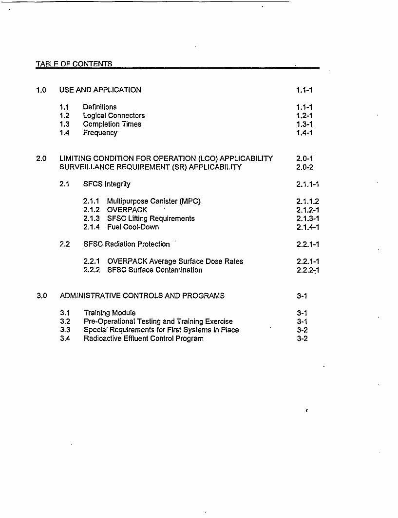
TABLE OF CONTENTS
1.0 USE AND APPLICATION 1.1-1
1.1 Definitions 1.1-11.2 Logical Connectors 1.2-11.3 Completion Times 1.3-11.4 Frequency 1.4-1
2.0 LIMITING CONDITION FOR OPERATION (LCO) APPLICABILITY 2.0-1SURVEILLANCE REQUIREMENT (SR) APPLICABILITY 2.0-2
2.1 SFCS Integrity 2.1.1-1
2.1.1 Multipurpose Canister (MPC) 2.1.1.22.1.2 OVERPACK 2.1.2-12.1.3 SFSC Lifting Requirements 2.1.3-12.1.4 Fuel Cool-Down 2.1.4-1
2.2 SFSC Radiation Protection 2.2.1-1
2.2.1 OVERPACK Average Surface Dose Rates 2.2.1-12.2.2 SFSC Surface Contamination 2.2.2.1
3.0 ADMINISTRATIVE CONTROLS AND PROGRAMS 3-1
3.1 Training Module 3-13.2 Pre-Operational Testing and Training Exercise 3-13.3 Special Requirements for First Systems in Place 3-23.4 Radioactive Effluent Control Program 3-2
Definitions1.1
1.0 USE AND APPLICATION
1.1 Definitions
K'fi=rr_I_ l_ I r - -_
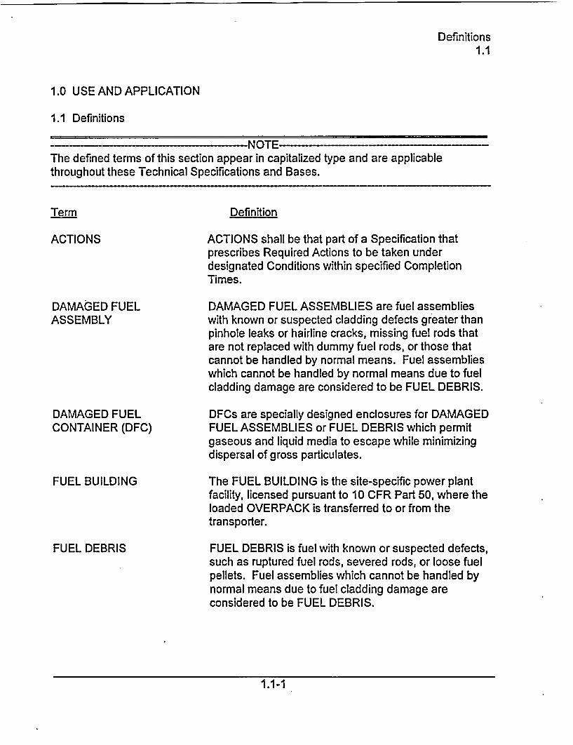
The defined terms of this section appear in capitalized type and are applicablethroughout these Technical Specifications and Bases.
Term Definition
ACTIONS ACTIONS shall be that part of a Specification thatprescribes Required Actions to be taken underdesignated Conditions within specified CompletionTimes.
DAMAGED FUELASSEMBLY
DAMAGED FUELCONTAINER (DFC)
FUEL BUILDING
FUEL DEBRIS
DAMAGED FUEL ASSEMBLIES are fuel assemblieswith known or suspected cladding defects greater thanpinhole leaks or hairline cracks, missing fuel rods thatare not replaced with dummy fuel rods, or those thatcannot be handled by normal means. Fuel assemblieswhich cannot be handled by normal means due to fuelcladding damage are considered to be FUEL DEBRIS.
DFCs are specially designed enclosures for DAMAGEDFUEL ASSEMBLIES or FUEL DEBRIS which permitgaseous and liquid media to escape while minimizingdispersal of gross particulates.
The FUEL BUILDING is the site-specific power plantfacility, licensed pursuant to 10 CFR Part 50, where theloaded OVERPACK is transferred to or from thetransporter.
FUEL DEBRIS is fuel with known or suspected defects,such as ruptured fuel rods, severed rods, or loose fuelpellets. Fuel assemblies which cannot be handled bynormal means due to fuel cladding damage areconsidered to be FUEL DEBRIS.
1.1-1
Definitions1.1
1.1 Definitions
INDEPENDENT SPENT FUELSTORAGE INSTALLATION(ISFSI)
INTACT FUEL ASSEMBLY
LOADING OPERATIONS
MULTI-PURPOSE CANISTER(MPC)
OVERPACK
PLANAR-AVERAGEINITIAL ENRICHMENT
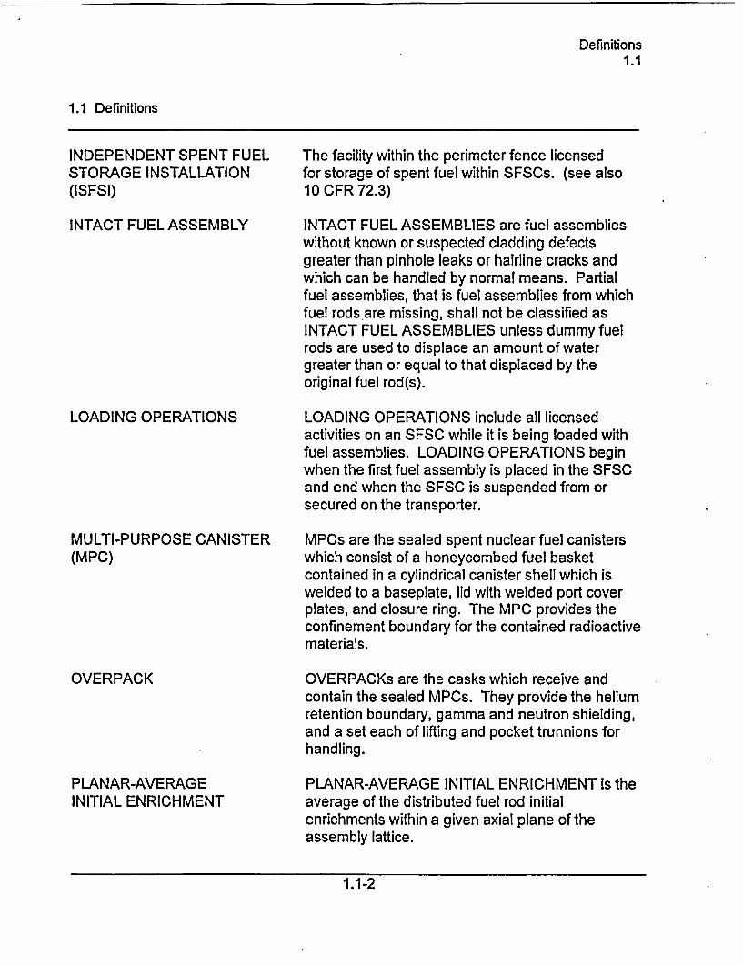
The facility within the perimeter fence licensedfor storage of spent fuel within SFSCs. (see also10 CFR 72.3)
INTACT FUEL ASSEMBLIES are fuel assemblieswithout known or suspected cladding defectsgreater than pinhole leaks or hairline cracks andwhich can be handled by normal means. Partialfuel assemblies, that is fuel assemblies from whichfuel rods are missing, shall not be classified asINTACT FUEL ASSEMBLIES unless dummy fuelrods are used to displace an amount of watergreater than or equal to that displaced by theoriginal fuel rod(s).
LOADING OPERATIONS include all licensedactivities on an SFSC while it is being loaded withfuel assemblies. LOADING OPERATIONS beginwhen the first fuel assembly is placed in the SFSCand end when the SFSC is suspended from orsecured on the transporter.
MPCs are the sealed spent nuclear fuel canisterswhich consist of a honeycombed fuel basketcontained in a cylindrical canister shell which iswelded to a baseplate, lid with welded port coverplates, and closure ring. The MPC provides theconfinement boundary for the contained radioactivematerials.
OVERPACKs are the casks which receive andcontain the sealed MPCs. They provide the heliumretention boundary, gamma and neutron shielding,and a set each of lifting and pocket trunnions forhandling.
PLANAR-AVERAGE INITIAL ENRICHMENT is theaverage of the distributed fuel rod initialenrichments within a given axial plane of theassembly lattice.
1.1-2
Definitions1.1
1.1 Definitions
SPENT FUEL STORAGECASKS (SFSCs)
STORAGE OPERATIONS
TRANSPORT OPERATIONS
UNLOADING OPERATIONS
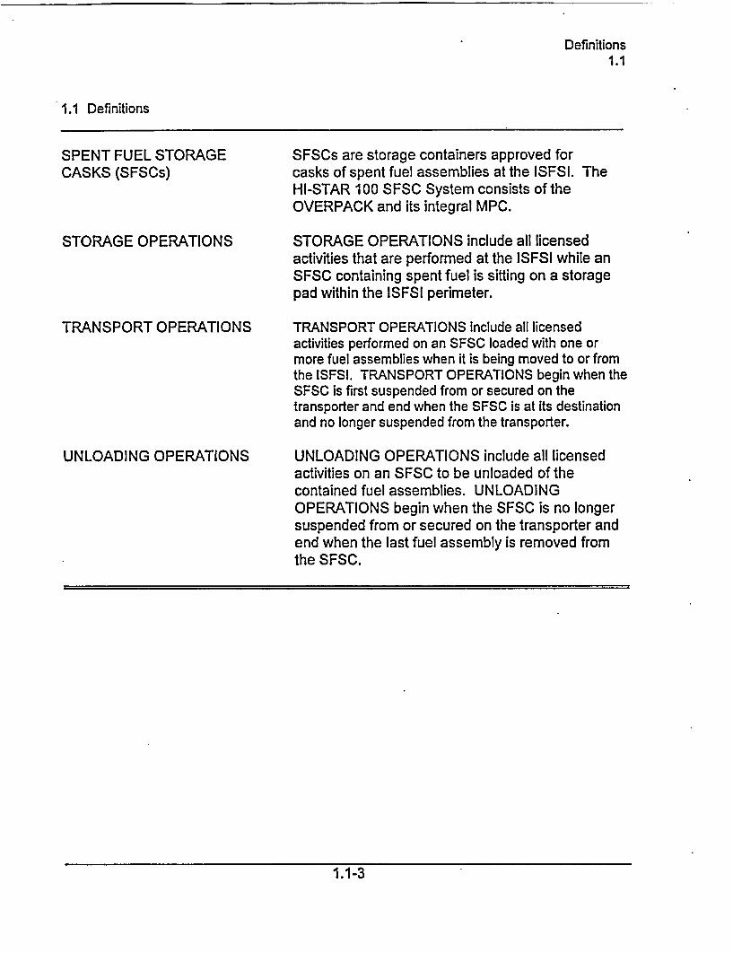
SFSCs are storage containers approved forcasks of spent fuel assemblies at the ISFSI. TheHI-STAR 100 SFSC System consists of theOVERPACK and its integral MPC.
STORAGE OPERATIONS include all licensedactivities that are performed at the ISFSI while anSFSC containing spent fuel is sitting on a storagepad within the ISFSI perimeter.
TRANSPORT OPERATIONS include all licensedactivities performed on an SFSC loaded with one ormore fuel assemblies when it is being moved to or fromthe ISFSI. TRANSPORT OPERATIONS begin when theSFSC is first suspended from or secured on thetransporter and end when the SFSC is at its destinationand no longer suspended from the transporter.
UNLOADING OPERATIONS include all licensedactivities on an SFSC to be unloaded of thecontained fuel assemblies. UNLOADINGOPERATIONS begin when the SFSC is no longersuspended from or secured on the transporter andend when the last fuel assembly is removed fromthe SFSC.
1.1-3
Logical Connectors1.2
1.0 USE AND APPLICATION
1.2 Logical Connectors
PURPOSE The purpose of this section is to explain the meaning of logicalconnectors.
Logical connectors are used in Technical Specifications (TS) todiscriminate between, and yet connect, discrete Conditions,Required Actions, Completion times, Surveillances, andFrequencies. The only logical connectors that appear in TS areAND and OR. The physical arrangement of these connectorsconstitutes logical conventions with specific meanings.
BACKGROUND Several levels of logic may be used to state Required Actions.These levels are identified by the placement (or nesting) of thelogical connectors and by the number assigned to each RequiredAction. The first level of logic is identified by the first digit of thenumber assigned to a Required Action and the placement of thelogical connector in the first level of nesting (i.e., left justified withthe number of the Required Action). The successive levels of logicare identified by additional digits of the Required Action numberand by successive indentations of the logical connectors.
When logical connectors are used to state a Condition, CompletionTime, Surveillance, or Frequency, only the first level of logic isused, and the logical connector is left justified with the statement ofthe Condition, Completion Time, Surveillance, or Frequency.
1.2-1
Logical Connectors1.2
1.2 Logical Connectors
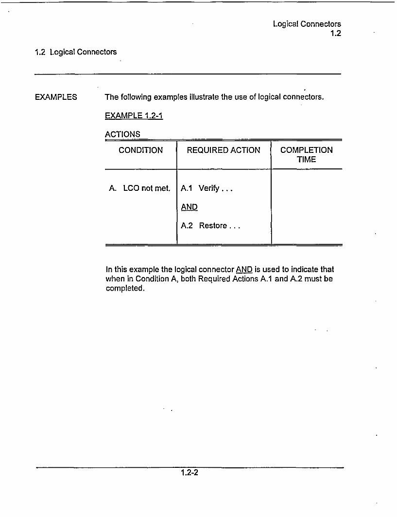
EXAMPLES The following examples illustrate the use of logical connectors.
EXAMPLE 1.2-1
ACTIONS
CONDITION REQUIRED ACTION COMPLETIONTIME
A. LCO not met. A.1 Verify ...
AND
A.2 Restore...
In this example the logical connector AND is used to indicate thatwhen in Condition A, both Required Actions A.1 and A.2 must becompleted.
1.2-2
Logical Connectors1.2
1.2 Logical Connectors
EXAMPLES(continued)
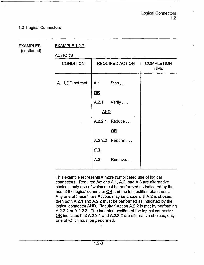
EXAMPLE 1.2-2
ACTIONS
CONDITION REQUIRED ACTION COMPLETIONTIME
A. LCO not met. A.1 Stop ...
OR
A.2.1 Verify...
AND
A.2.2.1 Reduce...
OR
A.2.2.2 Perform...
OR
A.3 Remove...
This example represents a more complicated use of logicalconnectors. Required Actions A.1, A.2, and A.3 are alternativechoices, only one of which must be performed as indicated by theuse of the logical connector OR and the left justified placement.Any one of these three Actions may be chosen. If A.2 is chosen,then both A.2.1 and A.2.2 must be performed as indicated by thelogical connector AND. Required Action A.2.2 is met by performingA.2.2.1 or A.2.2.2. The indented position of the logical connectorOR indicates that A.2.2.1 and A.2.2.2 are alternative choices, onlyone of which must be performed.
1.2-3
Completion Times1.3
1.0 USE AND APPLICATION
1.3 Completion Times
PURPOSE The purpose of this section is to establish the Completion Timeconvention and to provide guidance for its use.
BACKGROUND Limiting Conditions for Operation (LCOs) specify the lowestfunctional capability or performance levels of equipment requiredfor safe operation of the SFSC. The ACTIONS associated with anLCO state Conditions that typically describe the ways in which therequirements of the LCO can fail to be met. Specified with eachstated Condition are Required Action(s) and Completion Times(s).
DESCRIPTION The Completion Time is the amount of time allowed for completinga Required Action. It is referenced to the time of discovery of asituation (e.g., equipment or variable not within limits) that requiresentering an ACTIONS Condition unless otherwise specified,provided that the SFSC is in a specified condition stated in theApplicability of the LCO. Required Actions must be completed priorto the expiration of the specified Completion Time. An ACTIONSCondition remains in effect and the Required Actions apply until theCondition no longer exists or the SFSC is not within the LCOApplicability.
Once a Condition has been entered, subsequent subsystems,components, or variables expressed in the Condition, discovered tobe not within limits, will not result in separate entry into theCondition unless specifically stated. The Required Actions of theCondition continue to apply to each additional failure, withCompletion Times based on initial entry into the Condition.
When "Immediately" is used as a Completion Time, the Required Action should bepursued without delay and in a controlled manner.
1.3-1
Completion Times1.3
1.3 Completion Times
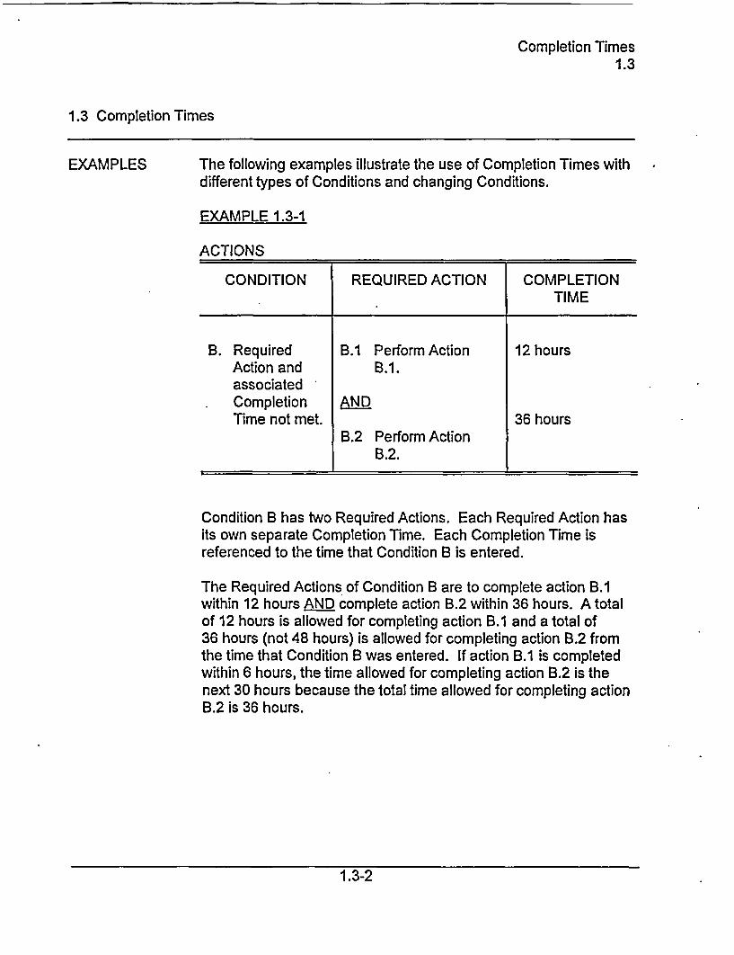
EXAMPLES The following examples illustrate the use of Completion Times withdifferent types of Conditions and changing Conditions.
EXAMPLE 1.3-1
ACTIONS
CONDITION REQUIRED ACTION COMPLETIONTIME
B. Required B.1 Perform Action 12 hoursAction and B.1.associatedCompletion ANDTime not met. 36 hours
B.2 Perform ActionB.2.
Condition B has two Required Actions. Each Required Action hasits own separate Completion Time. Each Completion Time isreferenced to the time that Condition B is entered.
The Required Actions of Condition B are to complete action B.1within 12 hours AND complete action B.2 within 36 hours. A totalof 12 hours is allowed for completing action B.1 and a total of36 hours (not 48 hours) is allowed for completing action B.2 fromthe time that Condition B was entered. If action B.1 is completedwithin 6 hours, the time allowed for completing action B.2 is thenext 30 hours because the total time allowed for completing actionB.2 is 36 hours.
1.3-2
Completion Times1.3
1.3 Completion Times
EXAMPLES(continued)
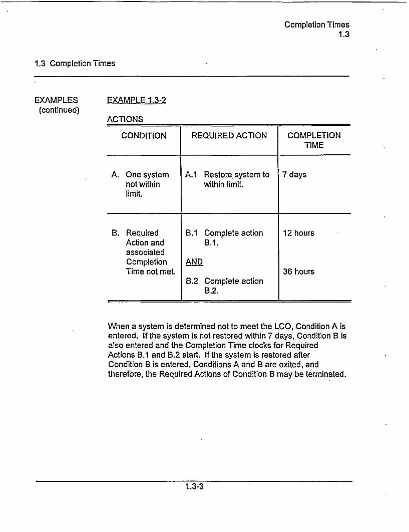
EXAMPLE 1.3-2
ACTIONS
CONDITION REQUIRED ACTION COMPLETIONTIME
A. One system A.1 Restore system to 7 daysnot within within limit.limit.
B. Required B.1 Complete action 12 hoursAction and B.1.associatedCompletion ANDTime not met. 36 hours
B.2 Complete actionB.2.
When a system is determined not to meet the LCO, Condition A isentered. If the system is not restored within 7 days, Condition B isalso entered and the Completion Time clocks for RequiredActions B.1 and B.2 start. If the system is restored afterCondition B is entered, Conditions A and B are exited, andtherefore, the Required Actions of Condition B may be terminated.
1.3-3
Completion Times1.3
1.3 Completion Times
EXAMPLES(continued)
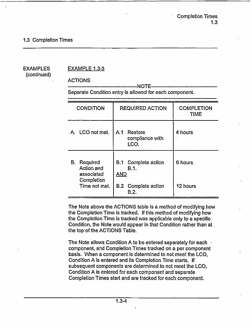
EXAMPLE 1.3-3
ACTIONS--- NOTE-
Separate Condition entry is allowed for each component.
CONDITION REQUIRED ACTION COMPLETIONTIME
A. LCO not met. A.1 Restore 4 hourscompliance withLCO.
B. Required B.1 Complete action 6 hoursAction and B.1.associated ANDCompletionTime not met. B.2 Complete action 12 hours
B.2.
The Note above the ACTIONS table is a method of modifying howthe Completion Time is tracked. If this method of modifying howthe Completion Time is tracked was applicable only to a specificCondition, the Note would appear in that Condition rather than atthe top of the ACTIONS Table.
The Note allows Condition A to be entered separately for eachcomponent, and Completion Times tracked on a per componentbasis. When a component is determined to not meet the LCO,Condition A is entered and its Completion Time starts. Ifsubsequent components are determined to not meet the LCO,Condition A is entered for each component and separateCompletion Times start and are tracked for each component.
1 .3-4
Frequency1.4
1.0 USE AND APPLICATION
1.4 Frequency
PURPOSE The purpose of this section is to define the proper use andapplication of Frequency requirements.
DESCRIPTION Each Surveillance Requirement (SR) has a specified Frequency inwhich the Surveillance must be met in order to meet the associatedLimiting Condition for Operation (LCO). An understanding of thecorrect application of the specified Frequency is necessary forcompliance with the SR.
The "specified Frequency" is referred to throughout this section andeach of the Specifications of Section 2.0, Surveillance Requirement(SR) Applicability. The "specified Frequency" consists of therequirements of the Frequency column of each SR.
Situations where a Surveillance could be required (i.e., itsFrequency could expire), but where it is not possible or not desiredthat it be performed until sometime after the associated LCO iswithin its Applicability, represent potential SR 2.0.4 conflicts. Toavoid these conflicts, the SR (i.e., the Surveillance or theFrequency) is stated such that it is only "required" when it can beand should be performed. With an SR satisfied, SR 2.0.4 imposesno restriction.
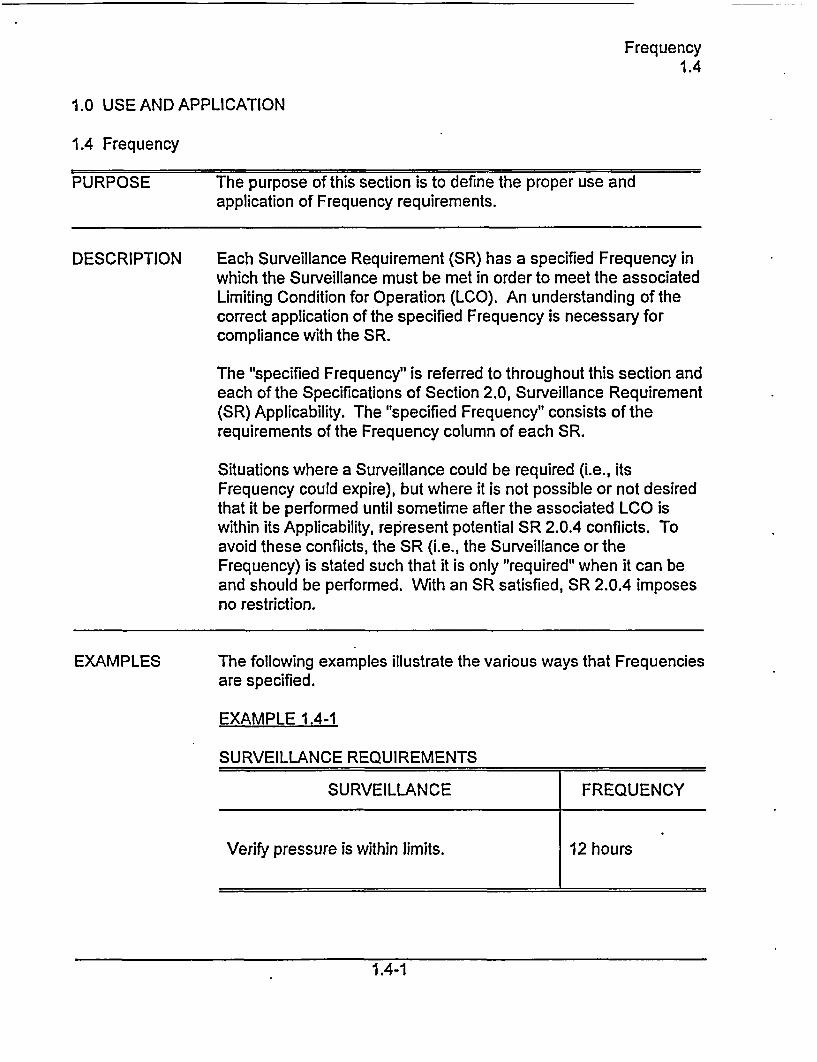
EXAMPLES The following examples illustrate the various ways that Frequenciesare specified.
EXAMPLE 1.4-1
SURVEILLANCE REQUIREMENTS
SURVEILLANCE FREQUENCY
Verify pressure is within limits. 12 hours
1.4-1
Frequency1.4
1.4 Frequency
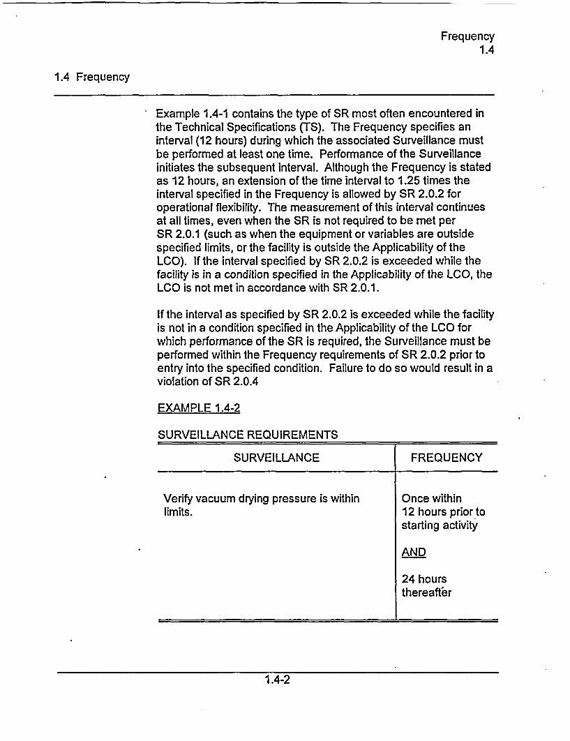
Example 1.4-1 contains the type of SR most often encountered inthe Technical Specifications (TS). The Frequency specifies aninterval (12 hours) during which the associated Surveillance mustbe performed at least one time. Performance of the Surveillanceinitiates the subsequent interval. Although the Frequency is statedas 12 hours, an extension of the time interval to 1.25 times theinterval specified in the Frequency is allowed by SR 2.0.2 foroperational flexibility. The measurement of this interval continuesat all times, even when the SR is not required to be met perSR 2.0.1 (such as when the equipment or variables are outsidespecified limits, or the facility is outside the Applicability of theLCO). If the interval specified by SR 2.0.2 is exceeded while thefacility is in a condition specified in the Applicability of the LCO, theLCO is not met in accordance with SR 2.0.1.
If the interval as specified by SR 2.0.2 is exceeded while the facilityis not in a condition specified in the Applicability of the LCO forwhich performance of the SR is required, the Surveillance must beperformed within the Frequency requirements of SR 2.0.2 prior toentry into the specified condition. Failure to do so would result in aviolation of SR 2.0.4
EXAMPLE 1.4-2
SURVEILLANCE REQUIREMENTS
SURVEILLANCE FREQUENCY
Verify vacuum drying pressure is within Once withinlimits. 12 hours prior to
starting activity
AND
24 hoursthereafter
1.4-2
Frequency1.4
1.4 Frequency
Example 1.4-2 has two Frequencies. The first is a one timeperformance Frequency, and the second is of the type shown inExample 1.4-1. The logical connector "AND" indicates that bothFrequency requirements must be met. Each time the exampleactivity is to be performed, the Surveillance must be performedwithin 12 hours prior to starting the activity.
The use of "once" indicates a single performance will satisfy thespecified Frequency (assuming no other Frequencies areconnected by "AND). This type of Frequency does not qualify forthe 25% extension allowed by SR 2.0.2.
"Thereafter" indicates future performances must be established perSR 2.0.2, but only after a specified condition is first met (i.e., the"once" performance in this example). If the specified activity iscanceled or not performed, the measurement of both intervalsstops. New intervals start upon preparing to restart the specifiedactivity.
1.4-3
LCO Applicability
LCO Applicability2.0
2.0 LIMITING CONDITION FOR OPERATION (LCO) APPLICABILITY
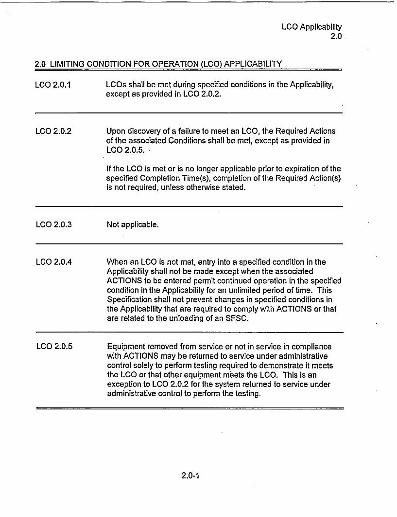
LCO 2.0.1 LCOs shall be met during specified conditions in the Applicability,except as provided in LCO 2.0.2.
LCO 2.0.2 Upon discovery of a failure to meet an LCO, the Required Actionsof the associated Conditions shall be met, except as provided inLCO 2.0.5.
If the LCO is met or is no longer applicable prior to expiration of thespecified Completion Time(s), completion of the Required Action(s)is not required, unless otherwise stated.
LCO 2.0.3 Not applicable.
LCO 2.0.4 When an LCO is not met, entry into a specified condition in theApplicability shall not be made except when the associatedACTIONS to be entered permit continued operation in the specifiedcondition in the Applicability for an unlimited period of time. ThisSpecification shall not prevent changes in specified conditions inthe Applicability that are required to comply with ACTIONS or thatare related to the unloading of an SFSC.
LCO 2.0.5 Equipment removed from service or not in service in compliancewith ACTIONS may be returned to service under administrativecontrol solely to perform testing required to demonstrate it meetsthe LCO or that other equipment meets the LCO. This is anexception to LCO 2.0.2 for the system returned to service underadministrative control to perform the testing.
2.0-1
SR Applicability2.0
2.0 SURVEILLANCE REQUIREMENT (SR) APPLICABILITY
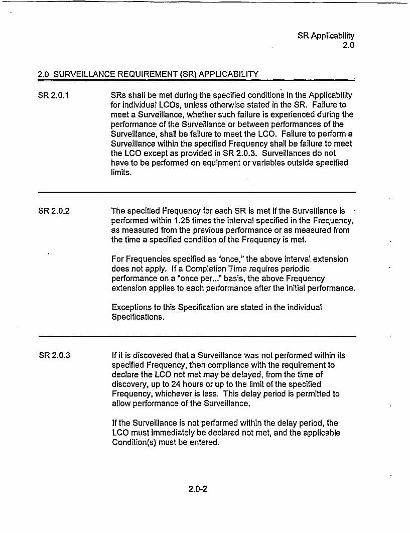
SR 2.0.1 SRs shall be met during the specified conditions in the Applicabilityfor individual LCOs, unless otherwise stated in the SR. Failure tomeet a Surveillance, whether such failure is experienced during theperformance of the Surveillance or between performances of theSurveillance, shall be failure to meet the LCO. Failure to perform aSurveillance within the specified Frequency shall be failure to meetthe LCO except as provided in SR 2.0.3. Surveillances do nothave to be performed on equipment or variables outside specifiedlimits.
SR 2.0.2 The specified Frequency for each SR is met if the Surveillance isperformed within 1.25 times the interval specified in the Frequency,as measured from the previous performance or as measured fromthe time a specified condition of the Frequency is met.
For Frequencies specified as once," the above interval extensiondoes not apply. If a Completion Time requires periodicperformance on a "once per..." basis, the above Frequencyextension applies to each performance after the initial performance.
Exceptions to this Specification are stated in the individualSpecifications.
SR 2.0.3 If it is discovered that a Surveillance was not performed within itsspecified Frequency, then compliance with the requirement todeclare the LCO not met may be delayed, from the time ofdiscovery, up to 24 hours or up to the limit of the specifiedFrequency, whichever is less. This delay period is permitted toallow performance of the Surveillance.
If the Surveillance is not performed within the delay period, theLCO must immediately be declared not met, and the applicableCondition(s) must be entered.
2.0-2
LCO Applicability2.0
2.0 SURVEILLANCE REQUIREMENT (SR) APPLICABILITY
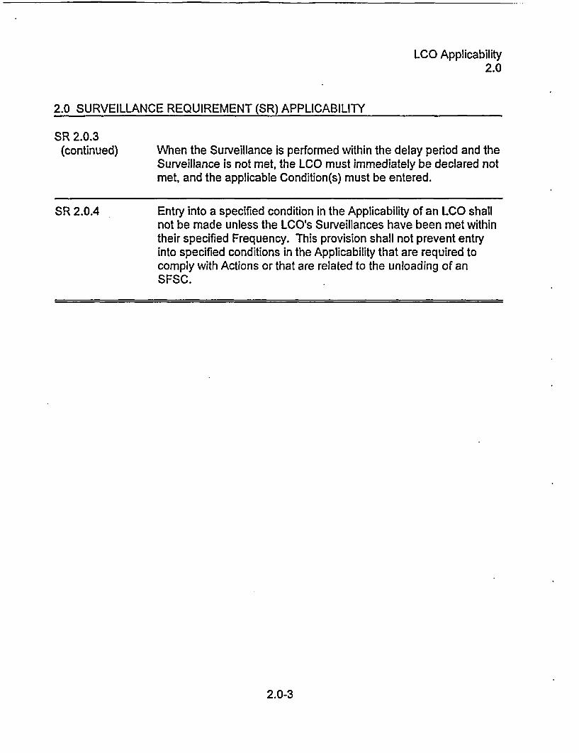
SR 2.0.3(continued) When the Surveillance is performed within the delay period and the
Surveillance is not met, the LCO must immediately be declared notmet, and the applicable Condition(s) must be entered.
SR 2.0.4 Entry into a specified condition in the Applicability of an LCO shallnot be made unless the LCO's Surveillances have been met withintheir specified Frequency. This provision shall not prevent entryinto specified conditions in the Applicability that are required tocomply with Actions or that are related to the unloading of anSFSC.
2.0-3
MULTIPURPOSE CANISTER2.1.1
2.1 SFSC INTEGRITY
2.1.1 Multipurpose Canister (MPC)
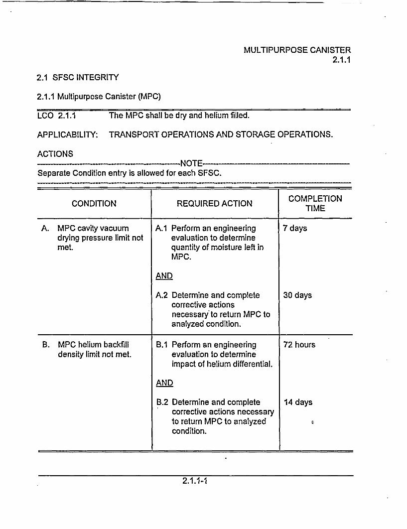
LCO 2.1.1 The MPC shall be dry and helium filled.
APPLICABILITY: TRANSPORT OPERATIONS AND STORAGE OPERATIONS.
ACTIONSNOTE-
Separate Condition entry is allowed for each SFSC.
CONDITION REQUIRED ACTION TIME
A. MPC cavity vacuum A.1 Perform an engineering 7 daysdrying pressure limit not evaluation to determinemet. quantity of moisture left in
MPC.
AND
A.2 Determine and complete 30 dayscorrective actionsnecessary to return MPC toanalyzed condition.
B. MPC helium backfill B.1 Perform an engineering 72 hoursdensity limit not met. evaluation to determine
impact of helium differential.
AND
B.2 Determine and complete 14 dayscorrective actions necessaryto return MPC to analyzed Econdition.
2.1.1-1
MULTIPURPOSE CANISTER2.1.1
CONDITION REQUIRED ACTION COMPLETION
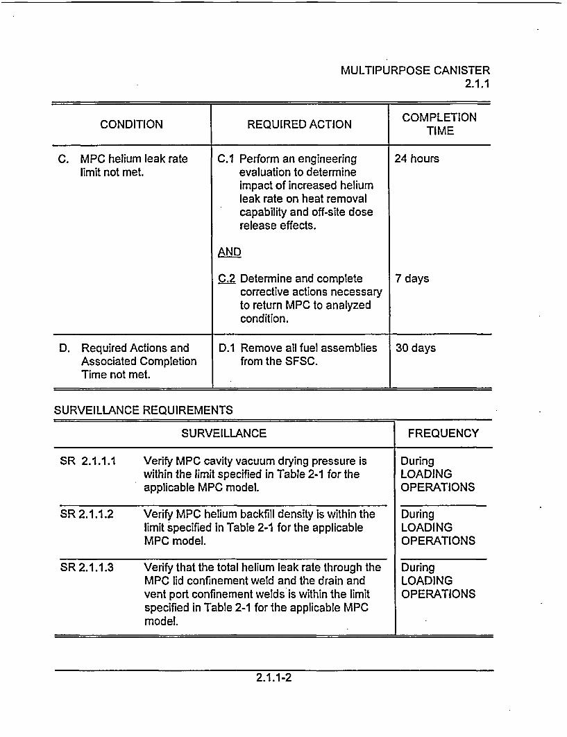
C. MPC helium leak rate C.1 Perform an engineering 24 hourslimit not met. evaluation to determine
impact of increased heliumleak rate on heat removalcapability and off-site doserelease effects.
AND
C.2 Determine and complete 7 dayscorrective actions necessaryto return MPC to analyzedcondition.
D. Required Actions and D.1 Remove all fuel assemblies 30 daysAssociated Completion from the SFSC.Time not met.
SURVEILLANCE REQUIREMENTS
SURVEILLANCE FREQUENCY
SR 2.1.1.1 Verify MPC cavity vacuum drying pressure is Duringwithin the limit specified in Table 2-1 for the LOADINGapplicable MPC model. OPERATIONS
SR 2.1.1.2 Verify MPC helium backfill density is within the Duringlimit specified in Table 2-1 for the applicable LOADINGMPC model. OPERATIONS
SR 2.1.1.3 Verify that the total helium leak rate through the DuringMPC lid confinement weld and the drain and LOADINGvent port confinement welds is within the limit OPERATIONSspecified in Table 2-1 for the applicable MPCmodel.
2.1 .1-2
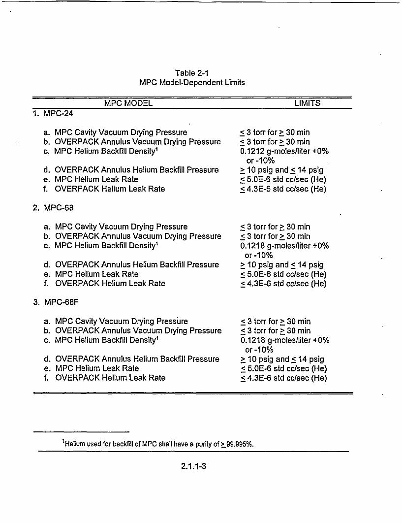
Table 2-1MPC Model-Dependent Limits
MPC MODEL LIMITS1. MPC-24
a. MPC Cavity Vacuum Drying Pressureb. OVERPACK Annulus Vacuum Drying Pressurec. MPC Helium Backfill Density'
d. OVERPACK Annulus Helium Backfill Pressuree. MPC Helium Leak Ratef. OVERPACK Helium Leak Rate
< 3 torr for > 30 minS 3 torr for > 30 min0.1212 g-moles/liter +0%
or -1 0%> 10 psig and < 14 psig< 5.OE-6 std cc/sec (He)< 4.3E-6 std cc/sec (He)
2. MPC-68
a. MPC Cavity Vacuum Drying Pressureb. OVERPACK Annulus Vacuum Drying Pressurec. MPC Helium Backfill Density'
d. OVERPACK Annulus Helium Backfill Pressuree. MPC Helium Leak Ratef. OVERPACK Helium Leak Rate
< 3 torr for > 30 min< 3 torr for > 30 min0.1218 g-moles/liter +0%
or -1 0%> 10 psig and < 14 psig< 5.OE-6 std cc/sec (He)< 4.3E-6 std cc/sec (He)
3. MPC-68F
a. MPC Cavity Vacuum Drying Pressureb. OVERPACK Annulus Vacuum Drying Pressurec. MPC Helium Backfill Density'
d. OVERPACK Annulus Helium Backfill Pressuree. MPC Helium Leak Ratef. OVERPACK Helium Leak Rate
< 3 torr for > 30 min< 3 torr for > 30 min0.1218 g-moles/liter +0%
or -1 0%> 10 psig and < 14 psig< 5.OE-6 std cc/sec (He)< 4.3E-6 std cc/sec (He)
'Helium used for backfill of MPC shall have a purity of > 99.995%.
2.1.1-3
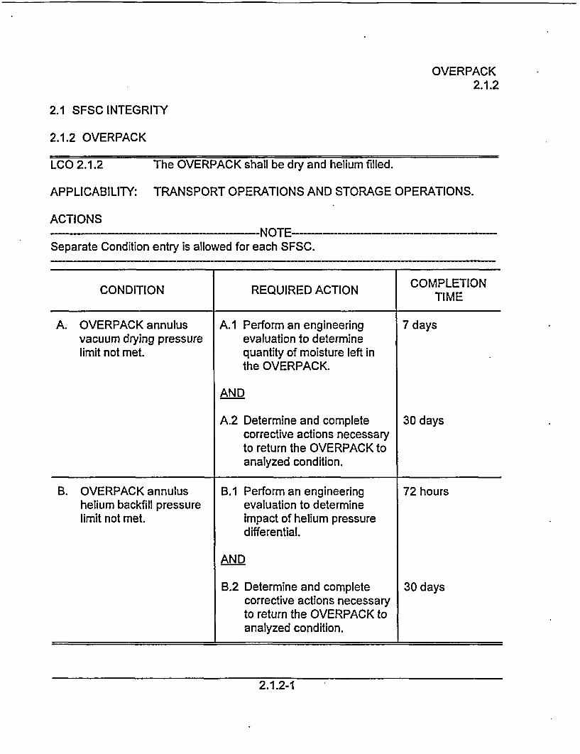
OVERPACK2.1.2
2.1 SFSC INTEGRITY
2.1.2 OVERPACK
LCO 2.1.2 The OVERPACK shall be dry and helium filled.
APPLICABILITY: TRANSPORT OPERATIONS AND STORAGE OPERATIONS.
ACTIONS--NOTNED-
Separate Condition entry is allowed for each SFSC.
CONDITION REQUIRED ACTION COMPLETION
A. OVERPACK annulus A.1 Perform an engineering 7 daysvacuum drying pressure evaluation to determinelimit not met. quantity of moisture left in
the OVERPACK.
AND
A.2 Determine and complete 30 dayscorrective actions necessaryto return the OVERPACK toanalyzed condition.
B. OVERPACK annulus B.1 Perform an engineering 72 hourshelium backfill pressure evaluation to determinelimit not met. impact of helium pressure
differential.
AND
B.2 Determine and complete 30 dayscorrective actions necessaryto return the OVERPACK toanalyzed condition.
2.1.2-1
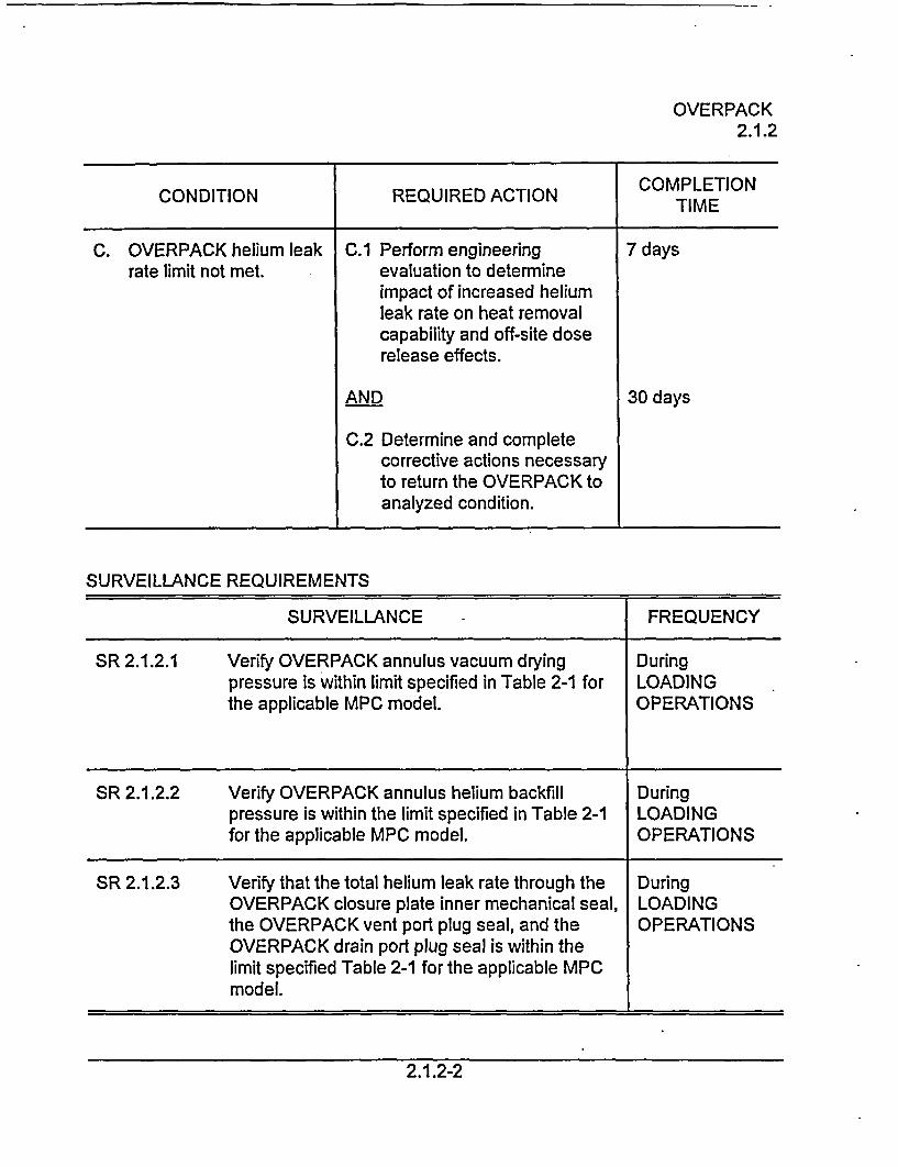
OVERPACK2.1.2
COMPLETIONCONDITION REQUIRED ACTION TIME
C. OVERPACK helium leak C.1 Perform engineering 7 daysrate limit not met. evaluation to determine
impact of increased heliumleak rate on heat removalcapability and off-site doserelease effects.
AND 30 days
C.2 Determine and completecorrective actions necessaryto return the OVERPACK toanalyzed condition.
SURVEILLANCE REQUIREMENTS
SURVEILLANCE - FREQUENCY
SR 2.1.2.1 Verify OVERPACK annulus vacuum drying Duringpressure is within limit specified in Table 2-1 for LOADINGthe applicable MPC model. OPERATIONS
SR 2.1.2.2 Verify OVERPACK annulus helium backfill Duringpressure is within the limit specified in Table 2-1 LOADINGfor the applicable MPC model. OPERATIONS
SR 2.1.2.3 Verify that the total helium leak rate through the DuringOVERPACK closure plate inner mechanical seal, LOADINGthe OVERPACK vent port plug seal, and the OPERATIONSOVERPACK drain port plug seal is within thelimit specified Table 2-1 for the applicable MPCmodel.
2.1.2-2
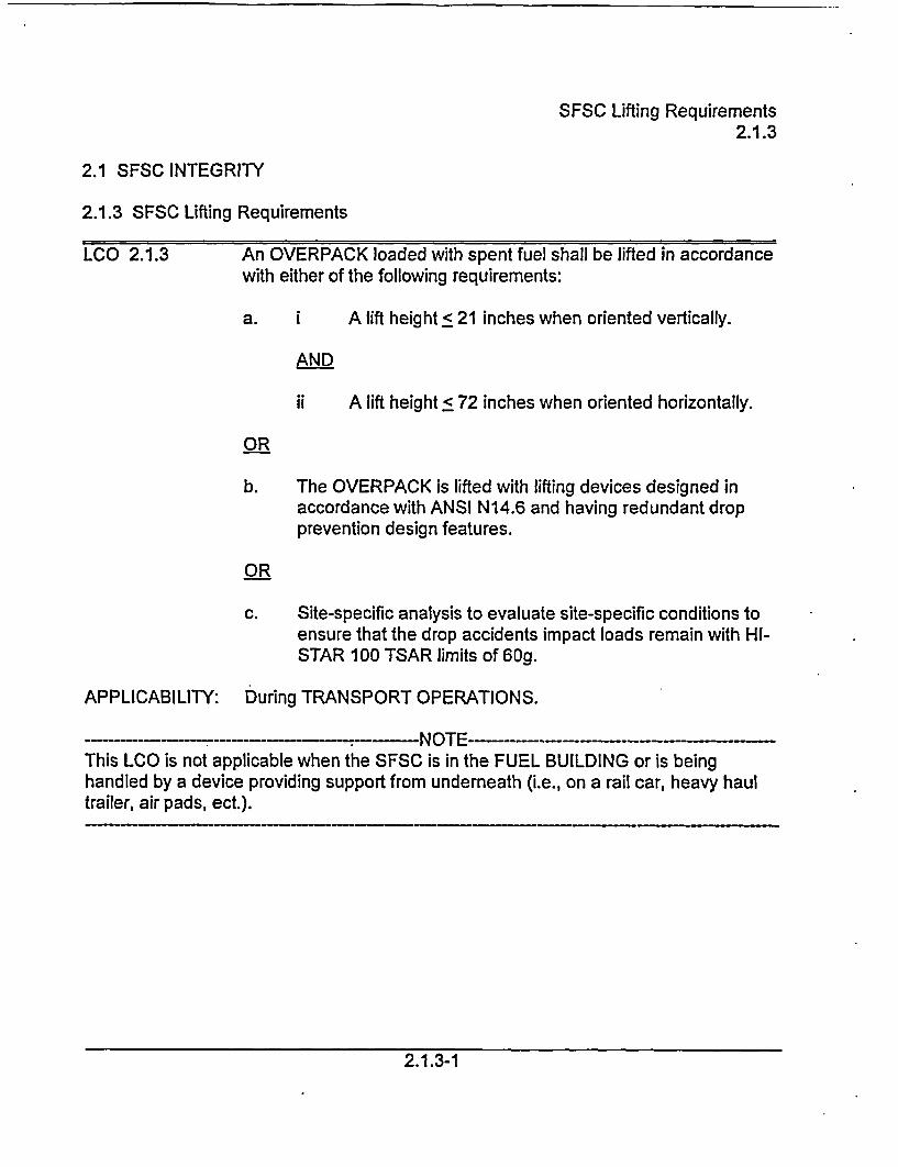
SFSC Lifting Requirements2.1.3
2.1 SFSC INTEGRITY
2.1.3 SFSC Lifting Requirements
LCO 2.1.3 An OVERPACK loaded with spent fuel shall be lifted in accordancewith either of the following requirements:
a. i A lift height < 21 inches when oriented vertically.
AND
ii A lift height < 72 inches when oriented horizontally.
OR
b. The OVERPACK is lifted with lifting devices designed inaccordance with ANSI N14.6 and having redundant dropprevention design features.
OR
c. Site-specific analysis to evaluate site-specific conditions toensure that the drop accidents impact loads remain with Hl-STAR 100 TSAR limits of 60g.
APPLICABILITY: During TRANSPORT OPERATIONS.
NOTE---…This LCO is not applicable when the SFSC is in the FUEL BUILDING or is beinghandled by a device providing support from underneath (i.e., on a rail car, heavy haultrailer, air pads, ect.).
2.1.3-1
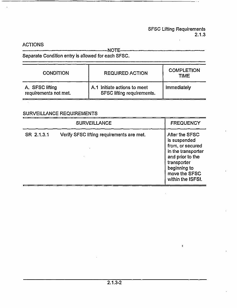
SFSC Lifting Requirements2.1.3
ACTIONSk I ^TC-I-GN I r-��
Separate Condition entry is allowed for each SFSC.
CONDITION REQUIRED ACTION COMPLETION
A. SFSC lifting A.1 Initiate actions to meet Immediatelyrequirements not met. SFSC lifting requirements.
SURVEILLANCE REQUIREMENTS
SURVEILLANCE FREQUENCY
SR 2.1.3.1 Verify SFSC lifting requirements are met. After the SFSCis suspendedfrom, or securedin the transporterand prior to thetransporterbeginning tomove the SFSCwithin the ISFSI.
2.1.3-2
Fuel Cool-Down2.1.4
2.1 SFSC INTEGRITY
2.1.4 Fuel Cool-Down
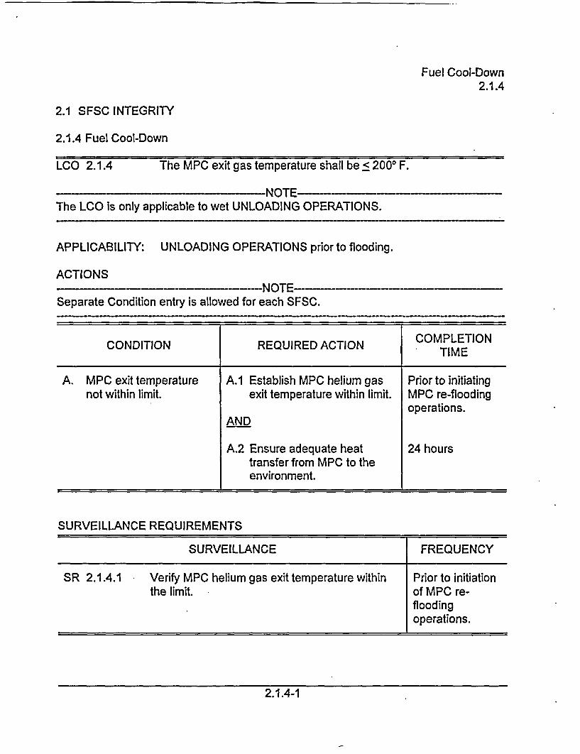
LCO 2.1.4 The MPC exit gas temperature shall be < 2000 F.
NOTE-The LCO is only applicable to wet UNLOADING OPERATIONS.
APPLICABILITY: UNLOADING OPERATIONS prior to flooding.
ACTIONS---- NOTE
Separate Condition entry is allowed for each SFSC.
COMPLETIONCONDITION REQUIRED ACTION TIME
A. MPC exit temperature A.1 Establish MPC helium gas Prior to initiatingnot within limit. exit temperature within limit. MPC re-flooding
operations.AND
A.2 Ensure adequate heat 24 hourstransfer from MPC to theenvironment.
SURVEILLANCE REQUIREMENTS
SURVEILLANCE FREQUENCY
SR 2.1.4.1 Verify MPC helium gas exit temperature within Prior to initiationthe limit. of MPC re-
floodingoperations.
2.1.4-1
Overpack Average Surface Dose Rates2.2.1
2.2 SFSC RADIATION PROTECTION
2.2.1 Overpack Average Surface Dose Rates
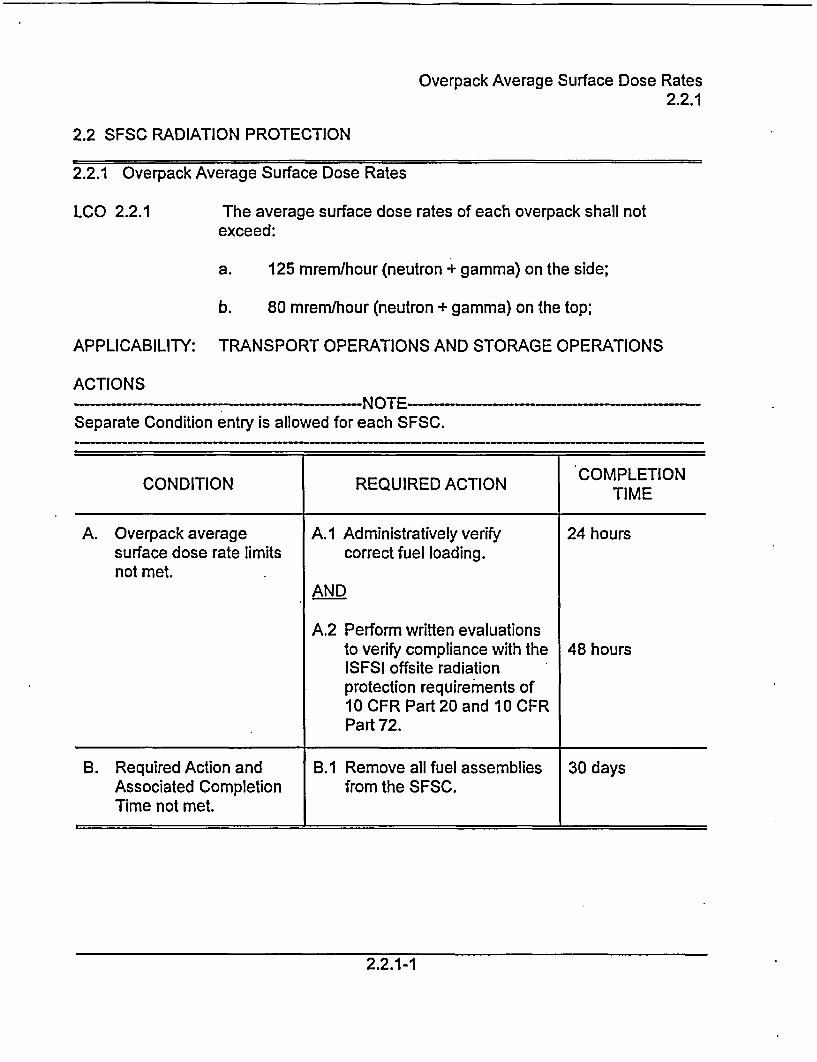
LCO 2.2.1 The average surface dose rates of each overpack shall notexceed:
a. 125 mrem/hour (neutron + gamma) on the side;
b. 80 mrem/hour (neutron + gamma) on the top;
APPLICABILITY: TRANSPORT OPERATIONS AND STORAGE OPERATIONS
ACTIONSI'JLJ r- �-
Separate Condition entry is allowed for each SFSC.
COMPLETIONCONDITION REQUIRED ACTION TIME
A. Overpack average A.1 Administratively verify 24 hourssurface dose rate limits correct fuel loading.not met.
AND
A.2 Perform written evaluationsto verify compliance with the 48 hoursISFSI offsite radiationprotection requirements of10 CFR Part 20 and 10 CFRPart 72.
B. Required Action and B.1 Remove all fuel assemblies 30 daysAssociated Completion from the SFSC.Time not met.
2.2.1-1
Overpack Average Surface Dose Rates2.2.1
SURVEILLANCE REQUIREMENTS
SURVEILLANCE FREQUENCY
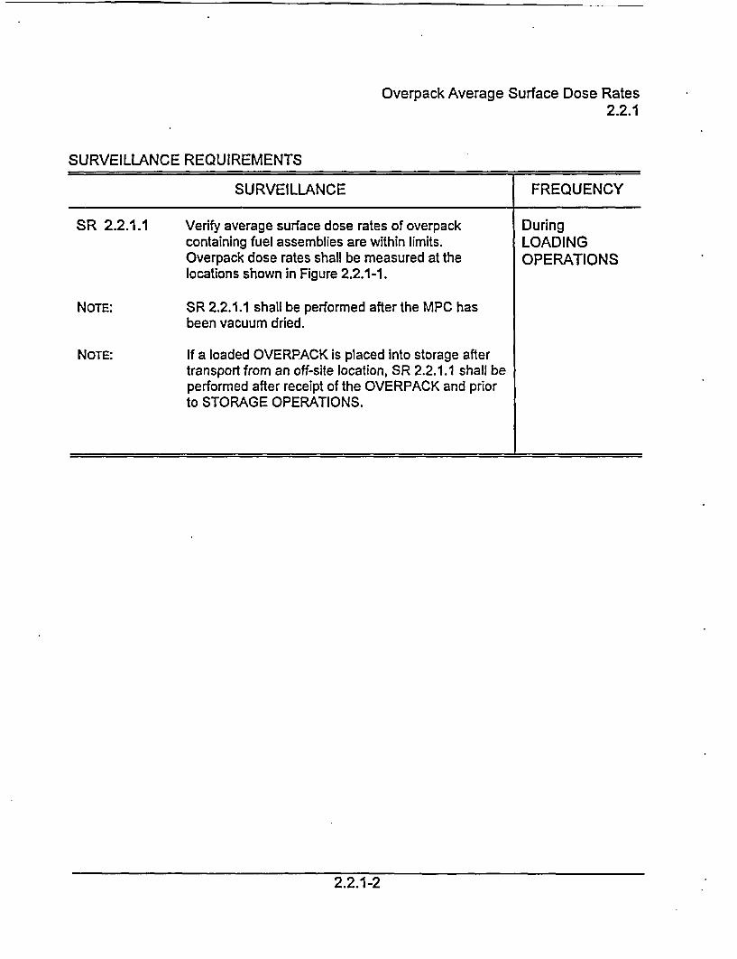
SR 2.2.1.1
NOTE:
NOTE:
Verify average surface dose rates of overpackcontaining fuel assemblies are within limits.Overpack dose rates shall be measured at thelocations shown in Figure 2.2.1-1.
SR 2.2.1.1 shall be performed after the MPC hasbeen vacuum dried.
If a loaded OVERPACK is placed into storage aftertransport from an off-site location, SR 2.2.1.1 shall beperformed after receipt of the OVERPACK and priorto STORAGE OPERATIONS.
DuringLOADINGOPERATIONS
2.2.1-2
Overpack Average Surface Dose Rates2;2.1
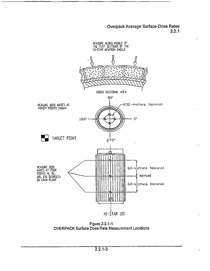
MEASURE ALONG MIDDLE OFTHE FLAT SECTIONS OF THEHI-S7AR NEUTRON SHIELD
MEASURE DOSE RATES ATTARGET POINTS SHOWN
32-inches Nominal
180 o.
%o TARGET POINT
I
MEASURE DOSE / 60-inchesRATES AT FOUR60icePOINTS (0, 90,180. 270 DEGREES) MID-PLAON EACH PLANE
60-inches
HI-STAR 100
Figure 2.2.1-1OVERPACK Surface Dose Rate Measurement Locations
Nominal
IE
NorninaI
2.2.1-3
SFSC Surface Contamination2.2.2
2.2 SFSC RADIATION PROTECTION
2.2.2 SFSC Surface Contamination
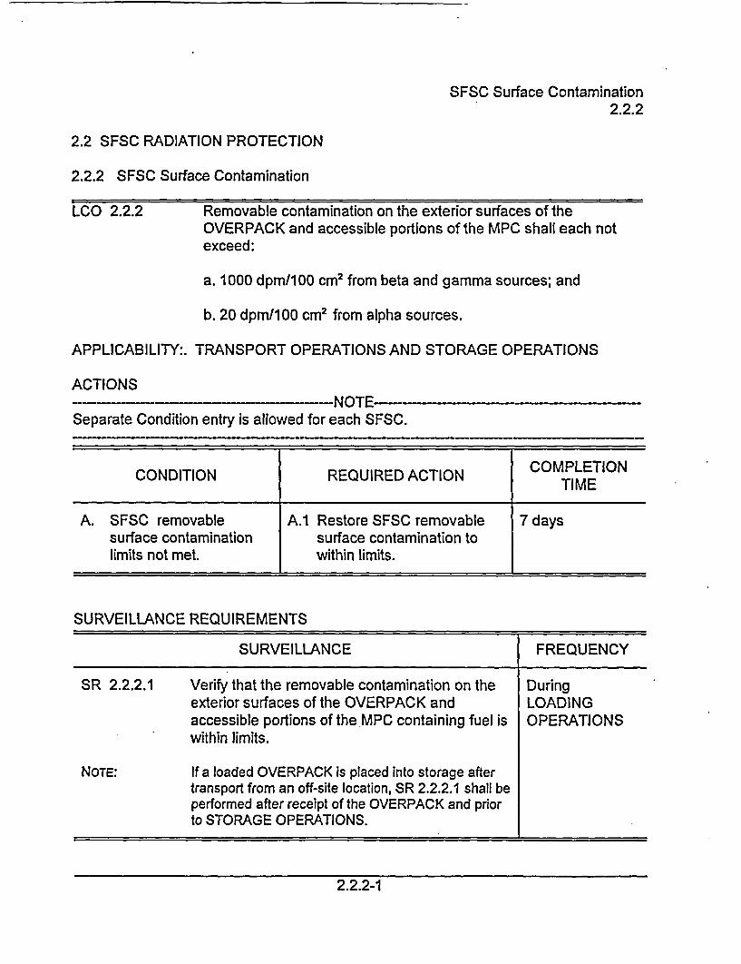
LCO 2.2.2 Removable contamination on the exterior surfaces of theOVERPACK and accessible portions of the MPC shall each notexceed:
a. 1000 dpm/100 cm2 from beta and gamma sources; and
b. 20 dpml100 cm2 from alpha sources.
APPLICABILITY:. TRANSPORT OPERATIONS AND STORAGE OPERATIONS
ACTIONS- --- NOTE--
Separate Condition entry is allowed for each SFSC.
CONDITION REQUIRED ACTION COMPLETION
A. SFSC removable A.1 Restore SFSC removable 7 dayssurface contamination surface contamination tolimits not met. within limits.
SURVEILLANCE REQUIREMENTS
SURVEILLANCE FREQUENCY
SR 2.2.2.1 Verify that the removable contamination on the Duringexterior surfaces of the OVERPACK and LOADINGaccessible portions of the MPC containing fuel is OPERATIONSwithin limits.
NOTE: If a loaded OVERPACK is placed into storage aftertransport from an off-site location, SR 2.2.2.1 shall beperformed after receipt of the OVERPACK and priorto STORAGE OPERATIONS.
2.2.2-1
CERTIFICATE OF COMPLIANCE NO. 1008
APPENDIX B
APPROVED CONTENTS AND DESIGN FEATURES
FOR THE HI-STAR 100 CASK SYSTEM
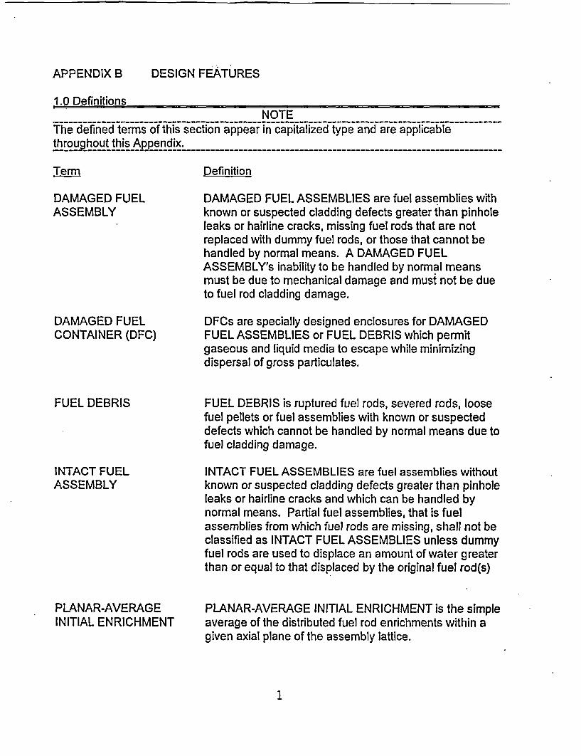
APPENDIX B DESIGN FEATURES
1.0 DefinitionsNOTE
The defined terms of this section appear in capitalized type and are applicablethroughout this Appendix.
------ --
-------------------------------------------------------------------- _
Term Definition
DAMAGED FUELASSEMBLY
DAMAGED FUELCONTAINER (DFC)
FUEL DEBRIS
INTACT FUELASSEMBLY
PLANAR-AVERAGEINITIAL ENRICHMENT
DAMAGED FUEL ASSEMBLIES are fuel assemblies withknown or suspected cladding defects greater than pinholeleaks or hairline cracks, missing fuel rods that are notreplaced with dummy fuel rods, or those that cannot behandled by normal means. A DAMAGED FUELASSEMBLY's inability to be handled by normal meansmust be due to mechanical damage and must not be dueto fuel rod cladding damage.
DFCs are specially designed enclosures for DAMAGEDFUEL ASSEMBLIES or FUEL DEBRIS which permitgaseous and liquid media to escape while minimizingdispersal of gross particulates.
FUEL DEBRIS is ruptured fuel rods, severed rods, loosefuel pellets or fuel assemblies with known or suspecteddefects which cannot be handled by normal means due tofuel cladding damage.
INTACT FUEL ASSEMBLIES are fuel assemblies withoutknown or suspected cladding defects greater than pinholeleaks or hairline cracks and which can be handled bynormal means. Partial fuel assemblies, that is fuelassemblies from which fuel rods are missing, shall not beclassified as INTACT FUEL ASSEMBLIES unless dummyfuel rods are used to displace an amount of water greaterthan or equal to that displaced by the original fuel rod(s)
PLANAR-AVERAGE INITIAL ENRICHMENT is the simpleaverage of the distributed fuel rod enrichments within agiven axial plane of the assembly lattice.
1
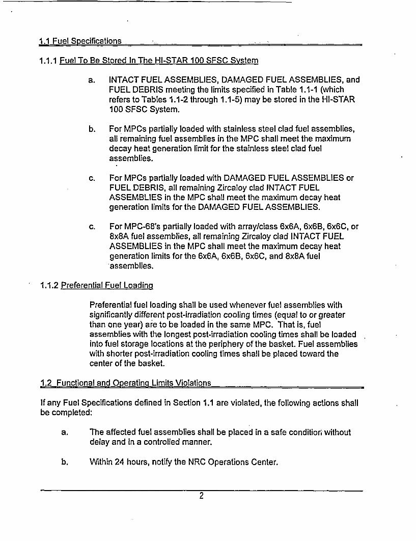
1.1 Fuel Specifications
1.1.1 Fuel To Be Stored In The HI-STAR 100 SFSC System
a. INTACT FUEL ASSEMBLIES, DAMAGED FUEL ASSEMBLIES, andFUEL DEBRIS meeting the limits specified in Table 1.1-1 (whichrefers to Tables 1.1-2 through 1.1-5) may be stored in the HI-STAR100 SFSC System.
b. For MPCs partially loaded with stainless steel clad fuel assemblies,all remaining fuel assemblies in the MPC shall meet the maximumdecay heat generation limit for the stainless steel clad fuelassemblies.
c. For MPCs partially loaded with DAMAGED FUEL ASSEMBLIES orFUEL DEBRIS, all remaining Zircaloy clad INTACT FUELASSEMBLIES in the MPC shall meet the maximum decay heatgeneration limits for the DAMAGED FUEL ASSEMBLIES.
c. For MPC-68's partially loaded with array/class 6x6A, 6x6B, 6x6C, or8x8A fuel assemblies, all remaining Zircaloy clad INTACT FUELASSEMBLIES in the MPC shall meet the maximum decay heatgeneration limits for the 6x6A, 6x6B, 6x6C, and 8x8A fuelassemblies.
1.1.2 Preferential Fuel Loading
Preferential fuel loading shall be used whenever fuel assemblies withsignificantly different post-irradiation cooling times (equal to or greaterthan one year) are to be loaded in the same MPC. That is, fuelassemblies with the longest post-irradiation cooling times shall be loadedinto fuel storage locations at the periphery of the basket. Fuel assemblieswith shorter post-irradiation cooling times shall be placed toward thecenter of the basket.
1.2 Functional and Operating Limits Violations
If any Fuel Specifications defined in Section 1.1 are violated, the following actions shallbe completed:
a. The affected fuel assemblies shall be placed in a safe condition withoutdelay and in a controlled manner.
b. Within 24 hours, notify the NRC Operations Center.
2
c. Within 30 days, sdbmit a special report which describes the cause of theviolation, and actions taken to restore compliance and prevent recurrence.
The above actions are not a substitute for the reporting requirements contained in 10CFR 72.75
1.3 Codes and Standards
The American Society of Mechanical Engineers Boiler and Pressure Vessel Code(ASME Code), 1995 Edition with Addenda through 1997, is the governing Code for theHI-STAR 100 Cask System, as clarified in Specification 1.3.1 below.
1.3.1 Exceptions to Codes. Standards, and Criteria
Table 1.3-1 lists approved exceptions to the ASME Code for the design of the HI-STAR100 Cask System.
1.3.2 Construction/Fabrication Exceptions to Codes. Standards, and Criteria
Proposed alternatives to the ASME Code, Section III, 1995 Edition with Addendathrough 1997 including exceptions allowed by Specification 1.3.1 may be usedwhen authorized by the Director of the Office of Nuclear Material Safety andSafeguards or designee. The request for such alternative should demonstratethat:
1. The proposed alternatives would provide an acceptable level of qualityand safety, or
2. Compliance with the specified requirements of the ASME Code, SectionIII, 1995 Edition with Addenda through 1997, would result in hardship orunusual difficulty without a compensating increase in the level of qualityand safety.
Requests for exceptions shall be submitted in accordance with 10 CFR72.4
1.4 Site Specific Parameters and Analyses
Site-specific parameters and analyses that will need verification by the systemuser, as a minimum, are as follows:
1. The temperature of 800F is the maximum allowed average yearlytemperature.
3
2. The allowed temperature extremes, averaged over a three day period,shall be greater than 401F, and less than 125 F.
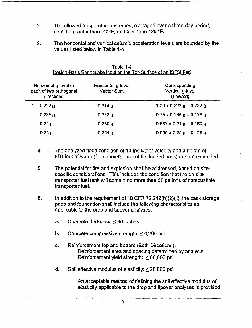
3. The horizontal and vertical seismic acceleration levels are bounded by thevalues listed below in Table 1-4.
Table 1-4Design-Basis Earthquake Input on the Tor, Surface of an ISFSI Pad
Horizontal g-level in Horizontal g-level Correspondingeach of two orthogonal Vector Sum Vertical g-level
directions (upward)
0.222 g 0.314 g 1.00 x 0.222 g = 0.222 g
0.235 g 0.332 g 0.75 x 0.2359 = 0.176 g
0.24 g 0.339 g 0.667 x 0.24 g = 0.160 g
0.25 g 0.354 g 0.500 x 0.25 g = 0.125 g
4. The analyzed flood condition of 13 fps water velocity and a height of656 feet of water (full submergence of the loaded cask) are not exceeded.
5. The potential for fire and explosion shall be addressed, based on site-specific considerations. This includes the condition that the on-sitetransporter fuel tank will contain no more than 50 gallons of combustibletransporter fuel.
6. In addition to the requirement of 10 CFR 72.212(b)(2)(ii), the cask storagepads and foundation shall include the following characteristics asapplicable to the drop and tipover analyses:
a. Concrete thickness: < 36 inches
b. Concrete compressive strength: < 4,200 psi
c. Reinforcement top and bottom (Both Directions):Reinforcement area and spacing determined by analysisReinforcement yield strength: < 60,000 psi
d. Soil effective modulus of elasticity: < 28,000 psi
An acceptable method of defining the soil effective modulus ofelasticity applicable to the drop and tipover analyses is provided
4
in Table 13 of NUREG/CR-6608 with soil classification inaccordance with ASTM-D2487-93, Standard Classification ofSoils for Enaineering Purposes (Unified Soil ClassificationSystem USCS) and density determination in accordance withASTM-D1586-84. Standard Test Method for Penetration Testand Split/Barrel Sampling of Soils.
7. In cases where engineered features (i.e., berms, shield walls) are used toensure that the requirements of 10 CFR 72.104(a) are met, such featuresare to be considered important to safety and must be evaluated todetermine the applicable Quality Assurance Category.
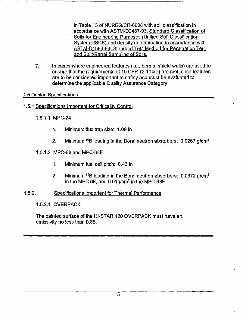
1.5 Design Specifications
1.5.1 Specifications Important for Criticality Control
1.5.1.1 MPC-24
1. Minimum flux trap size: 1.09 in
2. Minimum 11B loading in the Boral neutron absorbers: 0.0267 g/cm2
1.5.1.2 MPC-68 and MPC-68F
1. Minimum fuel cell pitch: 6.43 in
2. Minimum '0B loading in the Boral neutron absorbers: 0.0372 g/cm2
in the MPC 68, and 0.01g/cm2 in the MPC-68F.
1.5.2. Specifications Important for Thermal Performance
1.5.2.1 OVERPACK
The painted surface of the HI-STAR 100 OVERPACK must have anemissivity no less than 0.85.
5
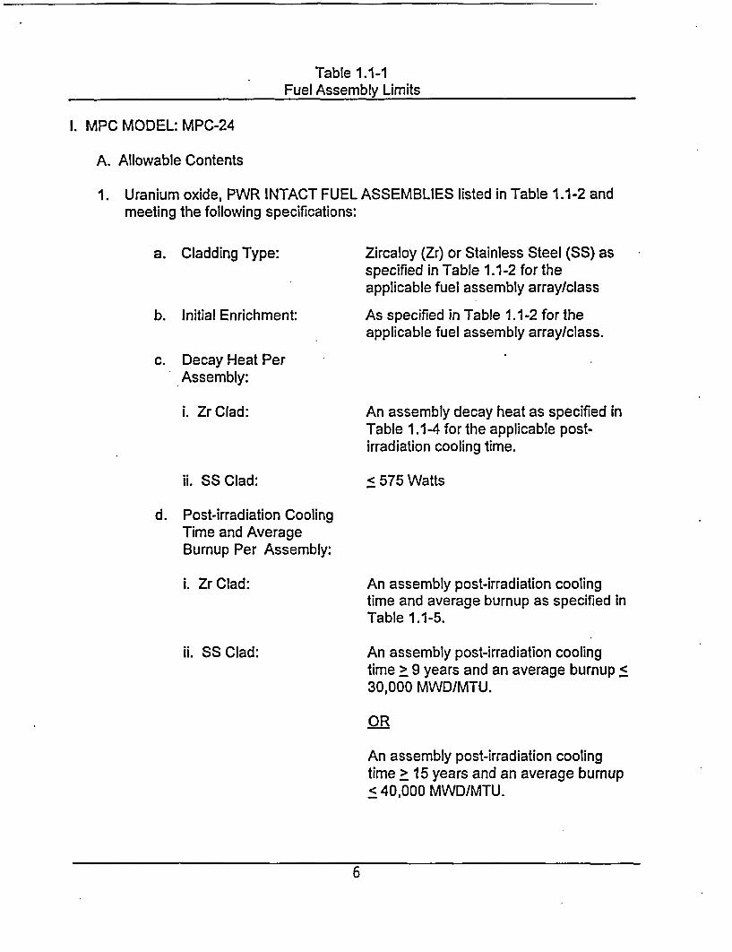
Table 1.1-1Fuel Assembly Limits
I. MPC MODEL: MPC-24
A. Allowable Contents
1. Uranium oxide, PWR INTACT FUEL ASSEMBLIES listed in Table 1.1-2 andmeeting the following specifications:
a. Cladding Type:
b. Initial Enrichment:
Zircaloy (Zr) or Stainless Steel (SS) asspecified in Table 1.1-2 for theapplicable fuel assembly array/class
As specified in Table 1.1-2 for theapplicable fuel assembly array/class.
c. Decay Heat PerAssembly:
i. Zr Clad:
ii. SS Clad:
An assembly decay heat as specified inTable 1.1-4 for the applicable post-irradiation cooling time.
< 575 Watts
d. Post-irradiation CoolingTime and AverageBurnup Per Assembly:
i. Zr Clad:
ii. SS Clad:
An assembly post-irradiation coolingtime and average burnup as specified inTable 1.1-5.
An assembly post-irradiation coolingtime > 9 years and an average burnup <30,000 MWD/MTU.
OR
An assembly post-irradiation coolingtime > 15 years and an average burnup< 40,000 MWD/MTU.
6
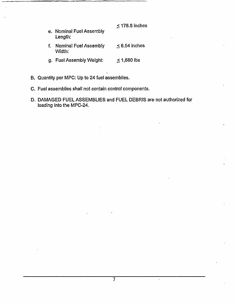
e. Nominal Fuel AssemblyLength:
f. Nominal Fuel AssemblyWidth:
g. Fuel Assembly Weight:
< 176.8 inches
< 8.54 inches
< 1,680 lbs
B. Quantity per MPC: Up to 24 fuel assemblies.
C. Fuel assemblies shall not contain control components.
D. DAMAGED FUEL ASSEMBLIES and FUEL DEBRIS are not authorized forloading into the MPC-24.
7
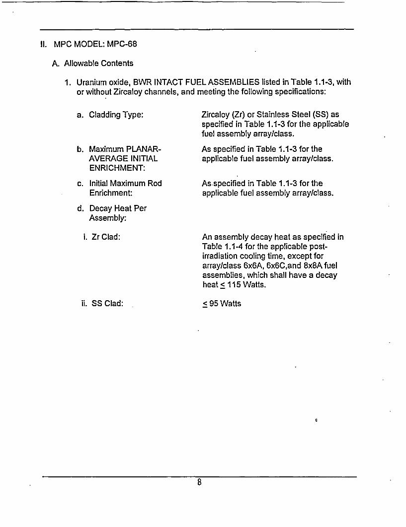
II. MPC MODEL: MPC-68
A. Allowable Contents
1. Uranium oxide, BWR INTACT FUEL ASSEMBLIES listed in Table 1.1-3, withor without Zircaloy channels, and meeting the following specifications:
a. Cladding Type:
b. Maximum PLANAR-AVERAGE INITIALENRICHMENT:
c. Initial Maximum RodEnrichment:
Zircaloy (Zr) or Stainless Steel (SS) asspecified in Table 1.1-3 for the applicablefuel assembly array/class.
As specified in Table 1.1-3 for theapplicable fuel assembly array/class.
As specified in Table 1.1-3 for theapplicable fuel assembly array/class.
d. Decay Heat PerAssembly:
i. Zr Clad:
ii. SS Clad:
An assembly decay heat as specified inTable 1.1-4 for the applicable post-irradiation cooling time, except forarray/class 6x6A, 6x6C,and 8x8A fuelassemblies, which shall have a decayheat 115 Watts.
< 95 Watts
r.
8
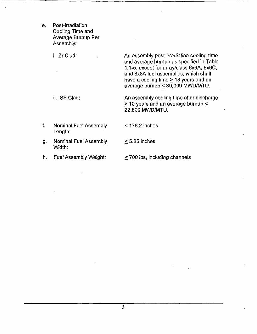
e. Post-irradiationCooling Time andAverage Burnup PerAssembly:
i. Zr Clad: An assembly post-irradiation cooling timeand average burnup as specified in Table1.1-5, except for array/class 6x6A, 6x6C,and 8x8A fuel assemblies, which shallhave a cooling time > 18 years and anaverage burnup < 30,000 MWD/MTU.
ii. SS Clad:
f. Nominal Fuel AssemblyLength:
g. Nominal Fuel AssemblyWidth:
h. Fuel Assembly Weight:
An assembly cooling time after discharge> 10 years and an average burnup <22,500 MWD/MTU.
< 176.2 inches
< 5.85 inches
< 700 bs, including channels
9
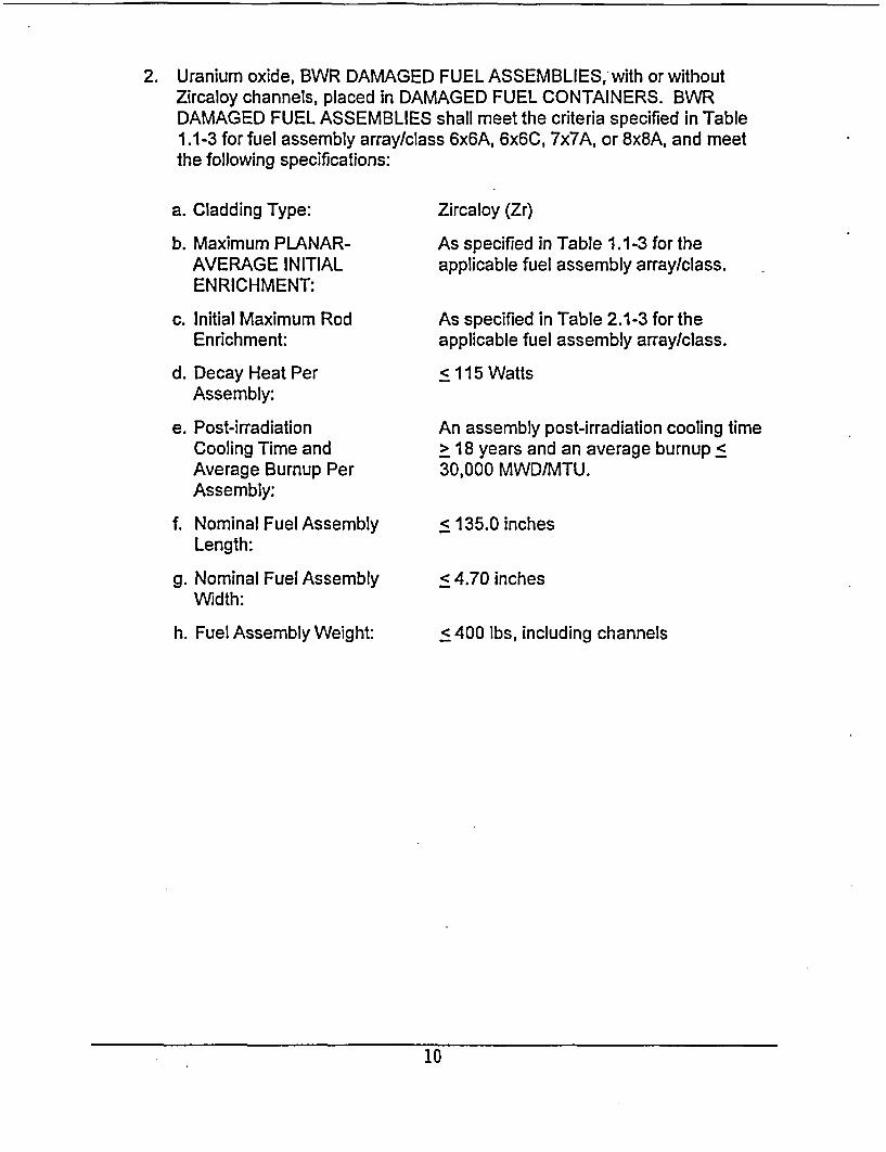
2. Uranium oxide, BWR DAMAGED FUEL ASSEMBLIES, with or withoutZircaloy channels, placed in DAMAGED FUEL CONTAINERS. BWRDAMAGED FUEL ASSEMBLIES shall meet the criteria specified in Table1.1-3 for fuel assembly array/class 6x6A, 6x6C, 7x7A, or 8x8A, and meetthe following specifications:
a. Cladding Type:
b. Maximum PLANAR-AVERAGE INITIALENRICHMENT:
c. Initial Maximum RodEnrichment:
d. Decay Heat PerAssembly:
e. Post-irradiationCooling Time andAverage Burnup PerAssembly:
f. Nominal Fuel AssemblyLength:
g. Nominal Fuel AssemblyWidth:
h. Fuel Assembly Weight:
Zircaloy (Zr)
As specified in Table 1.1-3 for theapplicable fuel assembly array/class.
As specified in Table 2.1-3 for theapplicable fuel assembly array/class.
< 115 Watts
An assembly post-irradiation cooling time> 18 years and an average burnup <30,000 MWD/MTU.
< 135.0 inches
< 4.70 inches
< 400 lbs, including channels
10
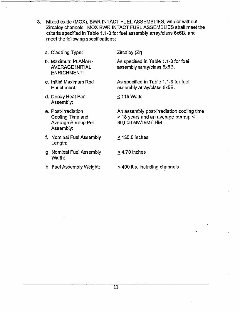
3. Mixed oxide (MOX), BWR INTACT FUEL ASSEMBLIES, with or withoutZircaloy channels. MOX BWR INTACT FUEL ASSEMBLIES shall meet thecriteria specified in Table 1.1-3 for fuel assembly array/class 6x6B, andmeet the following specifications:
a. Cladding Type:
b. Maximum PLANAR-AVERAGE INITIALENRICHMENT:
c. Initial Maximum RodEnrichment:
d. Decay Heat PerAssembly:
e. Post-irradiationCooling Time andAverage Burnup PerAssembly:
f. Nominal Fuel AssemblyLength:
g. Nominal Fuel AssemblyWidth:
h. Fuel Assembly Weight:
Zircaloy (Zr)
As specified in Table 1.1-3 for fuelassembly array/class 6x6B.
As specified in Table 1.1-3 for fuelassembly array/class 6x6B.
< 115 Watts
An assembly post-irradiation cooling time> 18 years and an average burnup <30,000 MWD/MTIHM.
< 135.0 inches
< 4.70 inches
< 400 bs, including channels
11
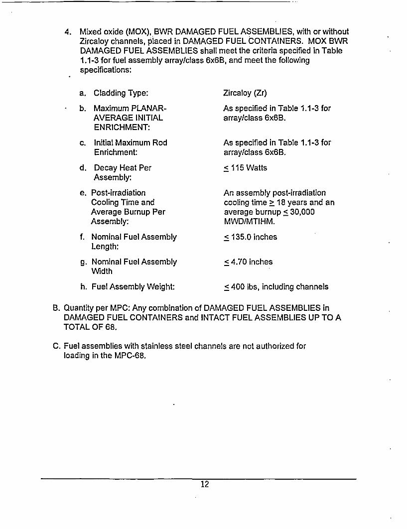
4. Mixed oxide (MOX), BWR DAMAGED FUEL ASSEMBLIES, with or withoutZircaloy channels, placed in DAMAGED FUEL CONTAINERS. MOX BWRDAMAGED FUEL ASSEMBLIES shall meet the criteria specified in Table1.1-3 for fuel assembly array/class 6x6B, and meet the followingspecifications:
a. Cladding Type:
b. Maximum PLANAR-AVERAGE INITIALENRICHMENT:
c. Initial Maximum RodEnrichment:
d. Decay Heat PerAssembly:
e. Post-irradiationCooling Time andAverage Burnup PerAssembly:
f. Nominal Fuel AssemblyLength:
g. Nominal Fuel AssemblyWidth
h. Fuel Assembly Weight:
Zircaloy (Zr)
As specified in Table 1.1-3 forarray/class 6x6B.
As specified in Table 1.1-3 forarray/class 6x6B.
< 115 Watts
An assembly post-irradiationcooling time > 18 years and anaverage burnup < 30,000MWD/MTIHM.
< 135.0 inches
< 4.70 inches
< 400 lbs, including channels
B. Quantity per MPC: Any combination of DAMAGED FUEL ASSEMBLIES inDAMAGED FUEL CONTAINERS and INTACT FUEL ASSEMBLIES UP TO ATOTAL OF 68.
C. Fuel assemblies with stainless steel channels are not authorized forloading in the MPC-68.
12
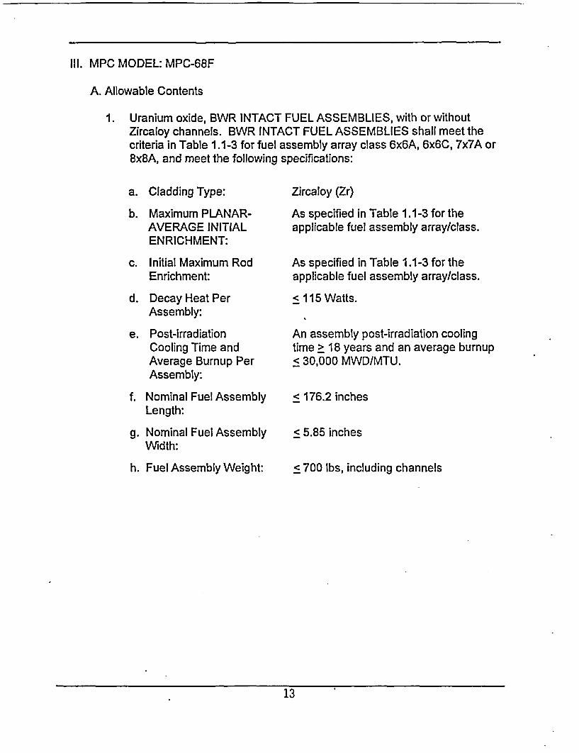
Ill. MPC MODEL: MPC-68F
A. Allowable Contents
1. Uranium oxide, BWR INTACT FUEL ASSEMBLIES, with or withoutZircaloy channels. BWR INTACT FUEL ASSEMBLIES shall meet thecriteria in Table 1.1-3 for fuel assembly array class 6x6A, 6x6C, 7x7A or8x8A, and meet the following specifications:
a. Cladding Type:
b. Maximum PLANAR-AVERAGE INITIALENRICHMENT:
c. Initial Maximum RodEnrichment:
d. Decay Heat PerAssembly:
e. Post-irradiationCooling Time andAverage Burnup PerAssembly:
f. Nominal Fuel AssemblyLength:
g. Nominal Fuel AssemblyWidth:
h. Fuel Assembly Weight:
Zircaloy (Zr)
As specified in Table 1.1-3 for theapplicable fuel assembly array/class.
As specified in Table 1.1-3 for theapplicable fuel assembly array/class.
< 115 Watts.
An assembly post-irradiation coolingtime > 18 years and an average burnup< 30,000 MWD/MTU.
< 176.2 inches
< 5.85 inches
< 700 lbs, including channels
13
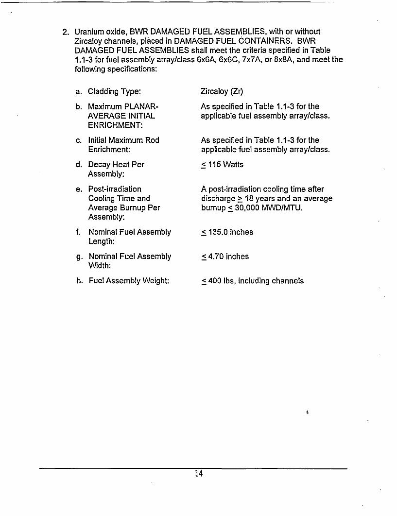
2. Uranium oxide, BWR DAMAGED FUEL ASSEMBLIES, with or withoutZircaloy channels, placed in DAMAGED FUEL CONTAINERS. BWRDAMAGED FUEL ASSEMBLIES shall meet the criteria specified in Table1.1-3 for fuel assembly array/class 6x6A, 6x6C, 7x7A, or 8x8A, and meet thefollowing specifications:
a. Cladding Type:
b. Maximum PLANAR-AVERAGE INITIALENRICHMENT:
c. Initial Maximum RodEnrichment:
d. Decay Heat PerAssembly:
e. Post-irradiationCooling Time andAverage Burnup PerAssembly:
f. Nominal Fuel AssemblyLength:
g. Nominal Fuel AssemblyWidth:
h. Fuel Assembly Weight:
Zircaloy (Zr)
As specified in Table 1.1-3 for theapplicable fuel assembly array/class.
As specified in Table 1.1-3 for theapplicable fuel assembly array/class.
< 115 Watts
A post-irradiation cooling time afterdischarge > 18 years and an averageburnup < 30,000 MWD/MTU.
< 135.0 inches
< 4.70 inches
< 400 lbs, including channels
14
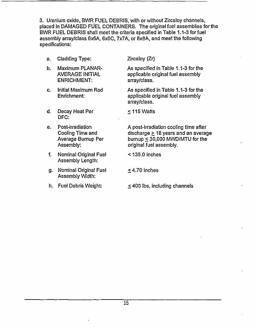
3. Uranium oxide, BWR FUEL DEBRIS, with or without Zircaloy channels,placed in DAMAGED FUEL CONTAINERS. The original fuel assemblies for theBWR FUEL DEBRIS shall meet the criteria specified in Table 1.1-3 for fuelassembly array/class 6x6A, 6x6C, 7x7A, or 8x8A, and meet the followingspecifications:
a. Cladding Type:
b. Maximum PLANAR-AVERAGE INITIALENRICHMENT:
c. Initial Maximum RodEnrichment:
d. Decay Heat PerDFC:
e. Post-irradiationCooling Time andAverage Bumup PerAssembly:
f. Nominal Original FuelAssembly Length:
g. Nominal Original FuelAssembly Width:
h. Fuel Debris Weight:
Zircaloy (Zr)
As specified in Table 1. 1-3 for theapplicable original fuel assemblyarray/class.
As specified in Table 1.1-3 for theapplicable original fuel assemblyarray/class.
< 115 Watts
A post-irradiation cooling time afterdischarge > 18 years and an averageburnup < 30,000 MWD/MTU for theoriginal fuel assembly.
< 135.0 inches
< 4.70 inches
< 400 lbs, including channels
15
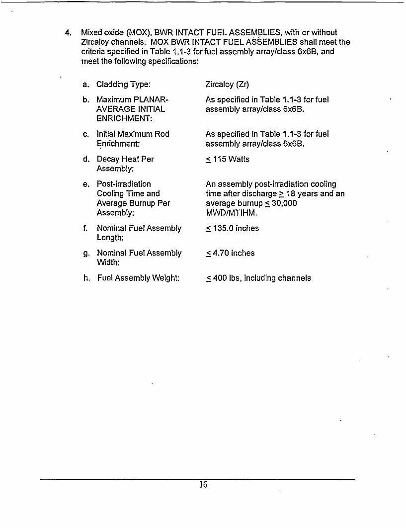
4. Mixed oxide (MOX), BWR INTACT FUEL ASSEMBLIES, with or withoutZircaloy channels. MOX BWR INTACT FUEL ASSEMBLIES shall meet thecriteria specified in Table 1.1-3 for fuel assembly array/class 6x6B, andmeet the following specifications:
a. Cladding Type:
b. Maximum PLANAR-AVERAGE INITIALENRICHMENT:
c. Initial Maximum RodEnrichment:
d. Decay Heat PerAssembly:
e. Post-irradiationCooling Time andAverage Burnup PerAssembly:
f. Nominal Fuel AssemblyLength:
g. Nominal Fuel AssemblyWidth:
h. Fuel Assembly Weight:
Zircaloy (Zr)
As specified in Table 1.1-3 for fuelassembly array/class 6x6B.
As specified in Table 1.1-3 for fuelassembly array/class 6x6B.
<115 Watts
An assembly post-irradiation coolingtime after discharge > 18 years and anaverage burnup < 30,000MWD/MTIHM.
< 135.0 inches
< 4.70 inches
< 400 lbs, including channels
16
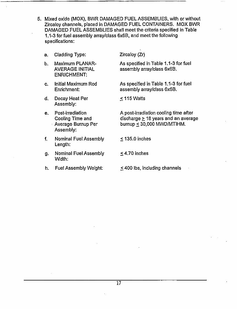
5. Mixed oxide (MOX), BWR DAMAGED FUEL ASSEMBLIES, with or withoutZircaloy channels, placed in DAMAGED FUEL CONTAINERS. MOX BWRDAMAGED FUEL ASSEMBLIES shall meet the criteria specified in Table1.1-3 for fuel assembly array/class 6x6B, and meet the followingspecifications:
a. Cladding Type:
b. Maximum PLANAR-AVERAGE INITIALENRICHMENT:
c. Initial Maximum RodEnrichment:
d. Decay Heat PerAssembly:
e. Post-irradiationCooling Time andAverage Burnup PerAssembly:
f. Nominal Fuel AssemblyLength:
g. Nominal Fuel AssemblyWidth:
h. Fuel Assembly Weight:
Zircaloy (Zr)
As specified in Table 1.1-3 for fuelassembly array/class 6x6B.
As specified in Table 1.1-3 for fuelassembly array/class 6x6B.
< 115 Watts
A post-irradiation cooling time afterdischarge > 18 years and an averageburnup < 30,000 MWD/MTIHM.
< 135.0 inches
< 4.70 inches
< 400 lbs, including channels
17
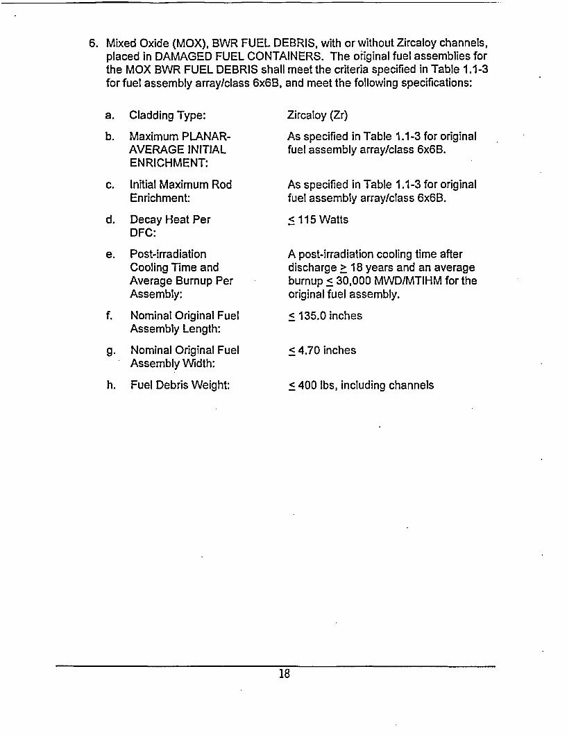
6. Mixed Oxide (MOX), BWR FUEL DEBRIS, with or without Zircaloy channels,placed in DAMAGED FUEL CONTAINERS. The original fuel assemblies forthe MOX BWR FUEL DEBRIS shall meet the criteria specified in Table 1.1-3for fuel assembly array/class 6x6B, and meet the following specifications:
a. Cladding Type:
b. Maximum PLANAR-AVERAGE INITIALENRICHMENT:
c. Initial Maximum RodEnrichment:
d. Decay Heat PerDFC:
e. Post-irradiationCooling Time andAverage Burnup PerAssembly:
f. Nominal Original FuelAssembly Length:
g. Nominal Original FuelAssembly Width:
h. Fuel Debris Weight:
Zircaloy (Zr)
As specified in Table 1.1-3 for originalfuel assembly array/class 6x6B.
As specified in Table 1.1-3 for originalfuel assembly array/class 6x6B.
< 115 Watts
A post-irradiation cooling time afterdischarge > 18 years and an averageburnup c 30,000 MWD/MTIHM for theoriginal fuel assembly.
c 135.0 inches
< 4.70 inches
< 400 lbs, including channels
18
B. Quantity per MPC:
Up to four (4) DFCs containing uranium oxide or MOX BWR FUEL DEBRIS.The remaining MPC-68F fuel storage locations may be filled with array/class6x6A, 6x6B, 6x6C, 7x7A, and 8x8A fuel assemblies of the following type, asapplicable:
a. Uranium oxide BWR INTACT FUEL ASSEMBLIES;
b. MOX BWR INTACT FUEL ASSEMBLIES;
c. Uranium oxide BWR DAMAGED FUEL ASSEMBLIES placed in DFCs; or
d. MOX BWR DAMAGED FUEL ASSEMBLIES placed in DFCs.
C. Fuel assemblies with stainless steel channels are not authorized for loading inthe MPC-68F.
19
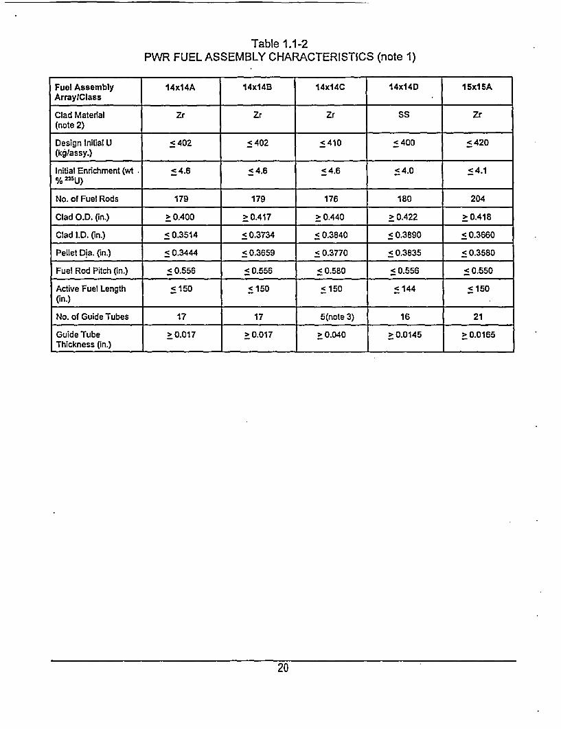
Table 1.1-2PWR FUEL ASSEMBLY CHARACTERISTICS (note 1)
Fuel Assembly 14x14A 14x14B 14x14C 14x14D 15x15AArraylClass .
Clad Material Zr Zr Zr SS Zr(note 2)
Design Initial U < 402 < 402 < 410 < 400 < 420(kgIassy.)
Initial Enrichment (wt . < 4.6 < 4.6 < 4.6 < 4.0 < 4.1% 23
5u)_ _ _ _ _ _ _ _ _ _ _ _ _ _ _ _ _ _ _ _
No. of Fuel Rods 179 179 176 180 204
Clad O.D. (in.) > 0.400 > 0.417 > 0.440 > 0.422 > 0.418
Clad .D. (in.) < 0.3514 < 0.3734 50.3840 < 0.3890 < 0.3660
Pellet Dia. (in.) < 0.3444 < 0.3659 < 0.3770 < 0.3835 <0.3580
Fuel Rod Pitch (in.) <0.556 < 0.556 < 0.580 < 0.556 < 0.550
Active Fuel Length < 150 < 150 < 150 < 144 < 150(in .) _ _ _ _ _ _ _ _ _ _ _ _ _ _ _ _ _ _ _ _ _ _ _ _ _ _ _ _ _ _ _ _ _ _ _ _ _ _ _ _
No. of Guide Tubes 17 17 5(note 3) 16 21
Guide Tube > 0.017 > 0.017 > 0.040 > 0.0145 > 0.0165Thickness (in.)
20
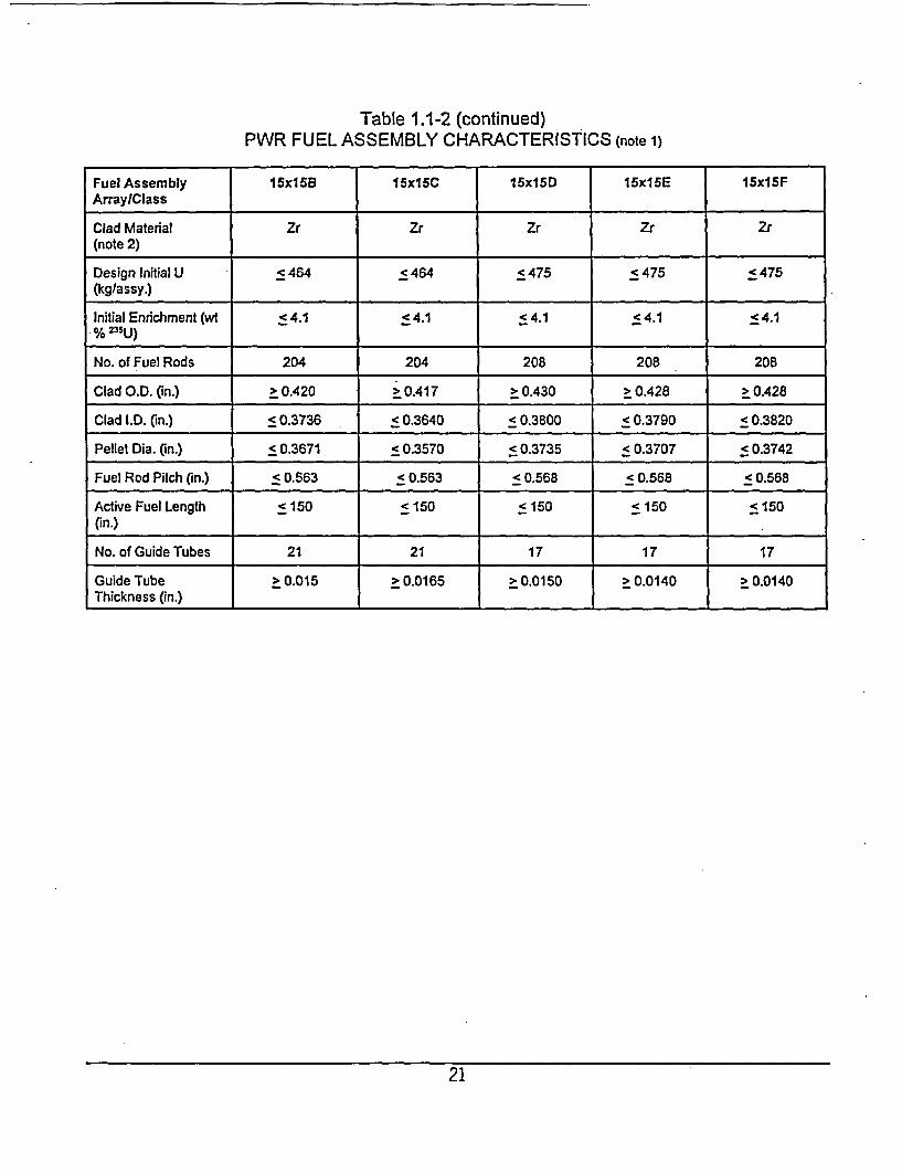
Table 1.1-2 (continued)PWR FUEL ASSEMBLY CHARACTERISTICS (note 1)
Fuel Assembly 16x15B 15x15C 15x16D 15x15E 15x15FArray/Class
Clad Material Zr Zr Zr Zr Zr(note 2) _
Design Initial U < 464 < 464 c 475 < 475 c 475(kglassy.)
Initial Enrichment (wt ; 4.1 1 4.1 < 4.1 < 4.1 < 4.1% 233U )_ _ _ _ _ _ _ _ _ _ _ _ _ _ _ _ _ _ _
No. of Fuel Rods 204 204 208 208 208
Clad O.D. (in.) > 0.420 > 0.417 > 0.430 > 0.428 > 0428
Clad l.D. (in.) < 0.3736 0.3640 < 0.3800 < 0.3790 < 0.3820
Pellet Dia. (in.) < 0.3671 < 0.3570 < 0.3735 < 0.3707 < 0.3742
Fuel Rod Pitch (in.) c<0.563 < 0.563 < 0.568 < 0.568 < 0.568
Active Fuel Length < 150 < 150 < 150 < 150 < 150(in .) _ _ _ _ _ _ _ _ _ _ _ _ _ _ _ _ _ _ _ _ _ _ _ _ _ _ _ _ _
No. of Guide Tubes 21 21 17 17 17
Guide Tube > 0.015 > 0.0165 > 0.0150 > 0.0140 > 0.0140Thickness (in.)
21
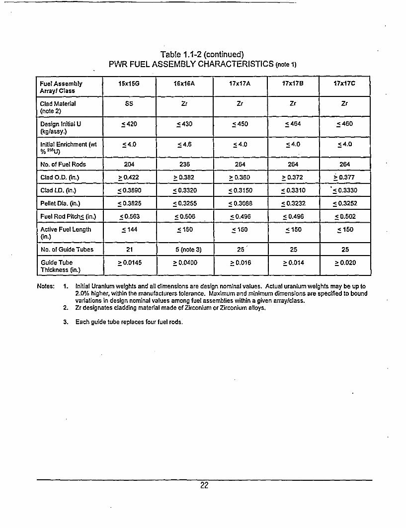
Table 1.1-2 (continued)PWR FUEL ASSEMBLY CHARACTERISTICS (note 1)
Fuel Assembly I5xl5G 16x16A 17x17A 1 7x1 17x17CArray/ Class
Clad Material SS Zr Zr Zr Zr(note 2)
Design Initial U < 420 < 430 < 450 c 464 < 460(kglassy.)Initial Enrichment (wt < 4.0 < 4.6 < 4.0 < 4.0 < 4.0%2 331) .
No. of Fuel Rods 204 236 264 264 264
Clad O.D. (in.) > 0.422 > 0.382 > 0.360 > 0.372 > 0.377
Clad l.D. (in.) c 0.3890 5 0.3320 < 0.3150 < 0.3310 :50.3330
Pellet Dia. (in.) < 0.3825 < 0.3255 < 0.3088 < 0.3232 < 0.3252
Fuel Rod Pitch< (in.) c 0.563 c 0.506 < 0.496 <0.496 c0.502
Active Fuel Length c 144 5 150 c 150 < 150 c 150(in .)_ _ _ _ _ _ _ _ _ _ _ _ _ _ _ _ _ _ _ _ _ _ _ _ _ _ _ _ _ _ _ _ _ _
No. of Guide Tubes 21 5 (note 3) 25 25 25
Guide Tube > 0.0145 > 0.0400 2 0.016 > 0.014 > 0.020Thickness (in.) I I _
Notes: 1. Initial Uranium weights and all dimensions are design nominal values. Actual uranium weights may be up to2.0% higher, within the manufacturers tolerance. Maximum and minimum dimensions are specified to boundvariations in design nominal values among fuel assemblies within a given array/class.
2. Zr designates cladding material made of Zirconium or Zirconium alloys.
3. Each guide tube replaces four fuel rods.
22
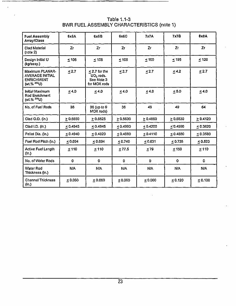
Table 1.1-3BWR FUEL ASSEMBLY CHARACTERISTICS (note 1)
Fuel Assembly 6x6A 6x6B 6x6C 7x7A 7x7B 8x8AArraylClass
Clad Material Zr Zr Zr Zr Zr Zr(note 2)
Design Initial U c 108 c108 < 108 < 100 c 195 c 120(kg/assy.)
Maximum PLANAR- < 2.7 < 2.7 for the < 2.7 < 2.7 < 4.2 c 2.7AVERAGE INITIAL UO2 rods.ENRICHMENT See Note 3(wt.% 235U) for MOX rods
Initial Maximum c 4.0 c 4.0 < 4.0 < 4.0 < 5.0 < 4.0Rod Enrichment(wt.% 235 U)
No. of Fuel Rods 36 36 (up to 9 36 49 49 64MOX rods)
Clad O.D. (in.) > 0.5550 > 0.5625 > 0.5630 > 0.4860 > 0.5630 > 0.4120
Clad .D. (in.) c 0.4945 < 0.4945 < 0.4990 < 0.4200 < 0.4990 < 0.3620
Pellet Dia. (in.) < 0.4940 c 0.4820 < 0.4880 < 0.4110 < 0.4880 < 0.3580
Fuel Rod Pitch (in.) < 0.694 < 0.694 < 0.740 < 0.631 < 0.738 < 0.523
Active Fuel Length <110 c110 < 77.5 <79 < 150 c110
(in.)
No. of Water Rods 0 0 0 0 0 0
Water Rod N/A NIA N/A N/A N/A N/AThickness (in.) .
Channel Thickness < 0.060 < 0.060 < 0.060 < 0.060 < 0.120 c0.100
(in.) I _ _ _ _ ___I
23
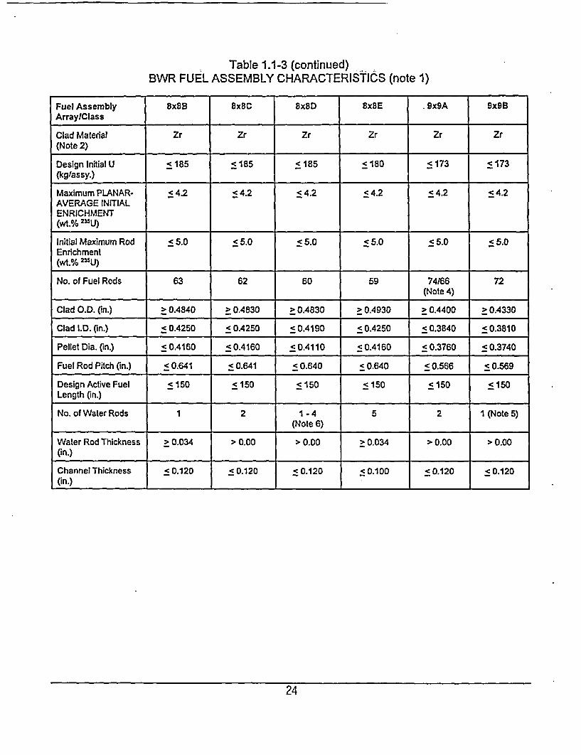
Table 1.1-3 (continued)BWR FUEL ASSEMBLY CHARACTERISTICS (note 1)
Fuel Assembly 8x8B 8x8C 8x8D 8x8E .9x9A 9x9BArraylClass
Clad Material Zr Zr Zr Zr Zr Zr(Note 2)
Design Initial U c 185 < 185 < 185 < 180 < 173 c173(kgflassy.)Maximum PLANAR- < 4.2 54.2 < 4.2 < 4.2 < 4.2 < 4.2AVERAGE INITIALENRICHMENT(wt.%
2 5U)
Initial Maximum Rod < 5.0 < 5.0 55.0 c 5.0 < 5.0 < 5.0Enrichment(wt.% 235U)
No. of Fuel Rods 63 62 60 59 74166 72| (Note 4)
Clad O.D. (in.) > 0.4840 > 0.4830 > 0.4830 > 0.4930 > 0.4400 > 0.4330
Clad .D. (in.) <0.4250 < 0.4250 < 0.4190 < 0.4250 < 0.3840 < 0.3810
Pellet Dia. (in.) < 0.4160 <0.4160 < 0.4110 < 0.4160 < 0.3760 < 0.3740
Fuel Rod Pitch (in.) < 0.641 50.641 < 0.640 < 0.640 < 0.566 5 0.569
Design Active Fuel <150 <150 <150 < 150 < 150 < 150Length (in.)
No. of Water Rods 1 2 1 - 4 5 2 1 (Note 5)(Note 6)
Water Rod Thickness > 0.034 > 0.00 > 0.00 > 0.034 > 0.00 > 0.00(in.)
Channel Thickness < 0.120 < 0.120 < 0.120 < 0.100 < 0.120 < 0.120(in .) _ _ _ _ _ _ _ _ _ _I ____ __ __ _ _ _ _ _ _ _ _
24
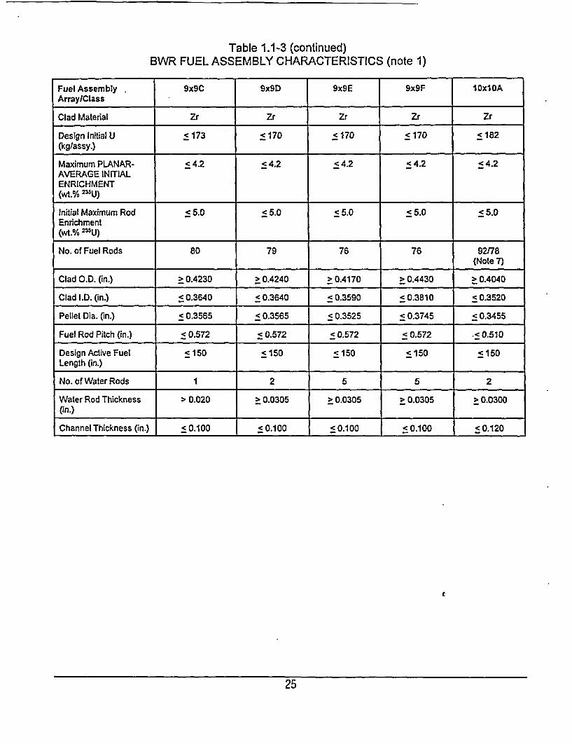
Table 1.1-3 (continued)BWR FUEL ASSEMBLY CHARACTERISTICS (note 1)
Fuel Assembly 9x9C 9x9D 9x9E 9x9F 1Oxi DAArray/Class .
Clad Material Zr Zr Zr Zr Zr
Design Initial U < 173 c 170 c 170 < 170 c 182(kglassy.)Maximum PLANAR- < 4.2 < 4.2 < 4.2 c 4.2 < 4.2AVERAGE INITIALENRICHMENT(wt.% =U)
Initial Maximum Rod < 5.0 < 5.0 < 5.0 < 5.0 < 5.0Enrichment(wt.% =U)
No. of Fuel Rods 80 79 76 76 92)78_ _ _ _ _ _ _ _ _ _ _ _ _ _ _ _ _ _ _ _ ______________ ______________ ~(N ote 7)
Clad O.D. (in.) > 0.4230 > 0.4240 > 0.4170 > 0.4430 > 0.4040
Clad I.D. (in.) < 0.3640 c 0.3640 c 0.3590 c 0.3810 c 0.3520
Pellet Dia. (in.) < 0.3565 < 0.3565 < 0.3525 < 0.3745 c0.3455
Fuel Rod Pitch (in.) < 0.572 < 0.572 < 0.572 < 0.572 .c0.510
Design Active Fuel c 150 < 150 c150 c 150 < 150Length (in.)
No. of Water Rods 1 2 5 5 2
Water Rod Thickness > 0.020 > 0.0305 > 0.0305 > 0.0305 > 0.0300(in.) Thickness (. c.001c00c 00.2
Channel Thickness (in.) 5 0.100 5 0.100 < 0.100 < 0.100 5 0.120
25

Table 1.1-3 (continued)BWR FUEL ASSEMBLY CHARACTERISTICS (note 1)
Fuel Assembly Array/Class 10x10B 10xIOC 10x10D 10x10E
Clad Material (note 2) Zr Zr SS SS
Design Initial U (kglassy.) < 182 < 180 < 125 < 125
Maximum PLANAR-AVERAGE < 4.2 < 4.2 < 4.0 < 4.0INITIAL ENRICHMENT(wt.% 25U)
Initial Maximum Rod < 5.0 < 5.0 < 5.0 < 5.0Enrichment(wt.% 25U)
No. of Fuel Rods 91/83 (note 8) 96 100 96
Clad O.D. (in.) > 0.3957 > 0.3790 > 0.3960 > 0.3940
Clad .D. (in.) < 0.3480 < 0.3294 < 0.3560 c 0.3500
Pellet Dia. (in.) < 0.3420 < 0.3224 < 0.3500 < 0.3430
Fuel Rod Pitch (in.) < 0.510 < 0.488 < 0.565 c 0.557
Design Active Fuel Length (in.) < 150 < 150 <83 c 83
No. of Water Rods 1 (Note 5) 5 (Note 9) 0 4
Water Rod Thickness (in.) > 0.00 > 0.034 N/A > 0.022
Channel Thickness (in.) < 0.120 c 0.055 < 0.080 < 0.080
1. Initial uranium weights and all dimensions are design nominal values. Actual uranium weights may be up to1.5% higher, within the manufacturer's tolerance. Maximum and minimum dimensions are specified to boundvariations In design nominal values among fuel assemblies within a given array/class.
2. Zr designates cladding material made of Zirconium or Zirconium alloys.3. < 0.612 wt.% 235U and < 1.578 wt,% total fuel fissile plutonium (239Pu and 241Pu).4. This assembly class contains 74 rods; 66 full length rods and 8 partial length rods.5. Square, replacing nine fuel rods.6. Variable7. This assembly class contains 92 total fuel rods; 78 full length rods and 14 partial length rods.8. This assembly class contains 91 total fuel rods; 83 full length rods and 8 partial length rods.9. One diamond shaped water rod replacing the four center fuel rods and four rectangualr water rods dividing
the assembly into four quadrants.
26
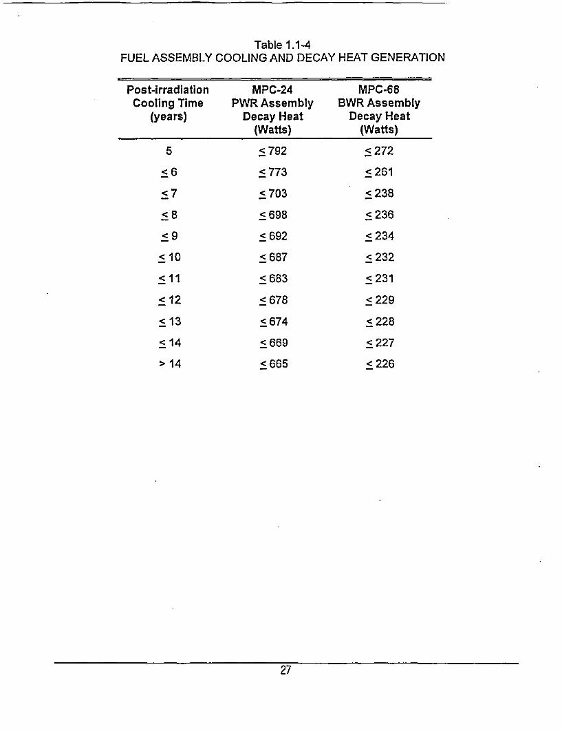
Table 1.1-4FUEL ASSEMBLY COOLING AND DECAY HEAT GENERATION
Post-irradiationCooling Time
(years)
5
<6
<7
<8
<
< 10
< 11
< 12
< 13
< 14
> 14
MPC-24PWR Assembly
Decay Heat(Watts)
< 792
< 773
< 703
<698
<692
<687
< 683
<678
< 674
< 669
< 665
MPC-68BWR Assembly
Decay Heat(Watts)
< 272
<261
< 238
< 236
<234
< 232
< 231
<229
< 228
< 227
< 226
27
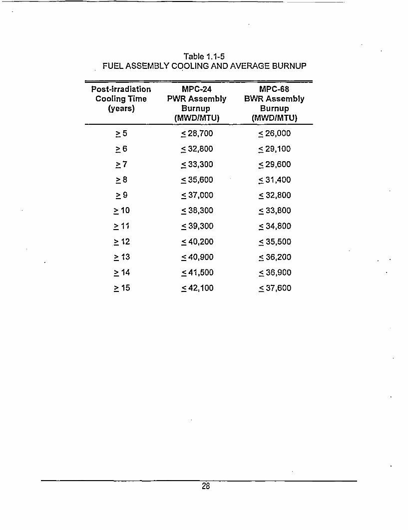
Table 1.1-5FUEL ASSEMBLY COOLING AND AVERAGE BURNUP
Post-irradiationCooling Time
(years)
>5
>6
>7
>8
>9
> 1 0
11
> 12
> 13
> 14
> 15
MPC-24PWR Assembly
Burnup(MWDIMTU)
< 28,700
< 32,800
< 33,300
< 35,600
< 37,000
< 38,300
< 39,300
< 40,200
< 40,900
< 41,500
< 42,100
MPC-68BWR Assembly
Burnup(MWD/MTU)
< 26,000
< 29,100
< 29,600
< 31,400
< 32,800
< 33,800
< 34,800
< 35,500
< 36,200
< 36,900
< 37,600
28
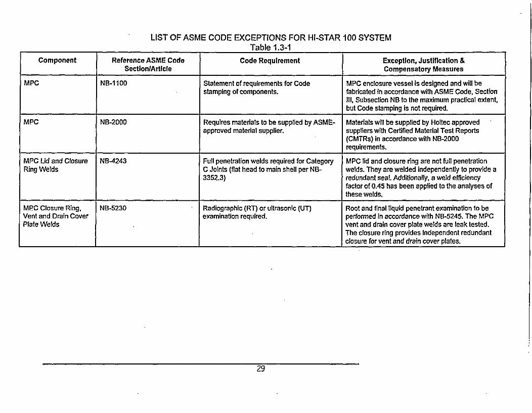
LIST OF ASME CODE EXCEPTIONS FOR HI-STAR 100 SYSTEMTable 1.3-1
Component Reference ASME Code Code Requirement Exception, Justification &Section/Article Compensatory Measures
MPC NB-1100 Statement of requirements for Code MPC enclosure vessel is designed and will bestamping of components. fabricated In accordance with ASME Code, Section
Ill, Subsection NB to the maximum practical extent,but Code stamping is not required.
MPC NB-2000 Requires materials to be supplied by ASME- Materials will be supplied by Holtec approvedapproved material supplier. suppliers with Certified Material Test Reports
(CMTRs) in accordance with NB-2000requirements.
MPC Lid and Closure NB-4243 Full penetration welds required for Category MPC lid and closure ring are not full penetrationRing Welds C Joints (flat head to main shell per NB- welds. They are welded independently to provide a
3352.3) redundant seal. Additionally, a weld efficiencyfactor of 0.45 has been applied to the analyses ofthese welds.
MPC Closure Ring, NB-5230 Radiographic (RT) or ultrasonic (UT) Root and final liquid penetrant examination to beVent and Drain Cover examination required. performed in accordance with NB-5245. The MPCPlate Welds vent and drain cover plate welds are leak tested.
The closure ring provides independent redundantclosure for vent and drain cover plates.
29
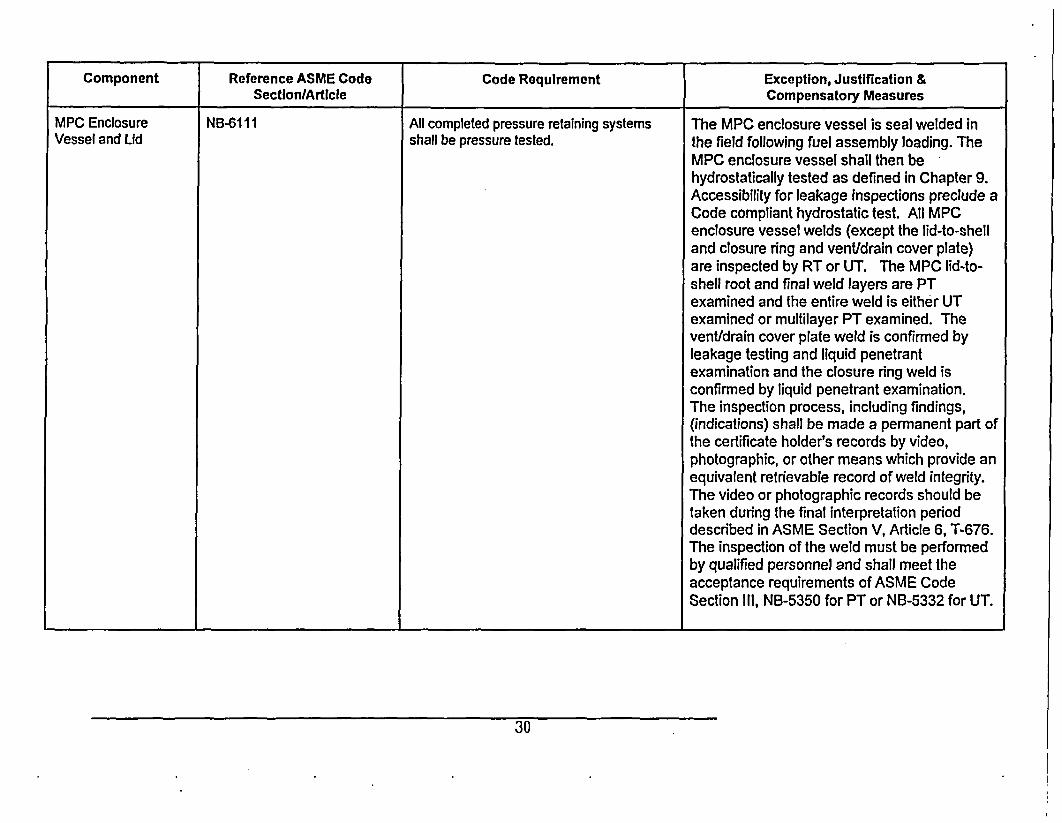
Component Reference ASME Code Code Requirement Exception, Justification &Section/Article Compensatory Measures
MPC Enclosure NB-61 11 All completed pressure retaining systems The MPC enclosure vessel is seal welded inVessel and Lid shall be pressure tested. the field following fuel assembly loading. The
MPC enclosure vessel shall then behydrostatically tested as defined in Chapter 9.Accessibility for leakage inspections preclude aCode compliant hydrostatic test. All MPCenclosure vessel welds (except the lid-to-shelland closure ring and vent/drain cover plate)are inspected by RT or UT. The MPC lid-to-shell root and final weld layers are PTexamined and the entire weld is either UTexamined or multilayer PT examined. Thevent/drain cover plate weld is confirmed byleakage testing and liquid penetrantexamination and the closure ring weld isconfirmed by liquid penetrant examination.The inspection process, including findings,(indications) shall be made a permanent part ofthe certificate holder's records by video,photographic, or other means which provide anequivalent retrievable record of weld integrity.The video or photographic records should betaken during the final interpretation perioddescribed in ASME Section V, Article 6, T-676.The inspection of the weld must be performedby qualified personnel and shall meet theacceptance requirements of ASME CodeSection III, NB-5350 for PT or NB-5332 for UT.
30
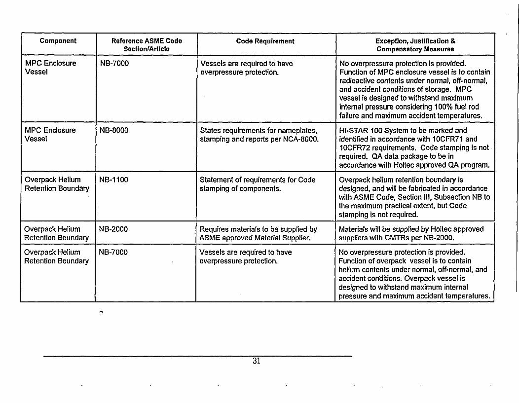
Component Reference ASME Code Code Requirement Exception, Justification &Section/Article Compensatory Measures
MPC Enclosure NB-7000 Vessels are required to have No overpressure protection is provided.Vessel overpressure protection. Function of MPC enclosure vessel is to contain
radioactive contents under normal, off-normal,and accident conditions of storage. MPCvessel is designed to withstand maximuminternal pressure considering 100% fuel rodfailure and maximum accident temperatures.
MPC Enclosure NB-8000 States requirements for nameplates, HI-STAR 100 System to be marked andVessel stamping and reports per NCA-8000. identified in accordance with IOCFR71 and
10CFR72 requirements. Code stamping is notrequired. QA data package to be inaccordance with Holtec approved QA program.
Overpack Helium NB-1100 Statement of requirements for Code Overpack helium retention boundary isRetention Boundary stamping of components. designed, and will be fabricated in accordance
with ASME Code, Section III, Subsection NB tothe maximum practical extent, but Codestamping is not required.
Overpack Helium NB-2000 Requires materials to be supplied by Materials will be supplied by Holtec approvedRetention Boundary ASME approved Material Supplier. suppliers with CMTRs per NB-2000.
Overpack Helium NB-7000 Vessels are required to have No overpressure protection is provided.Retention Boundary overpressure protection. Function of overpack vessel is to contain
helium contents under normal, off-normal, andaccident conditions. Overpack vessel isdesigned to withstand maximum internalpressure and maximum accident temperatures.
31
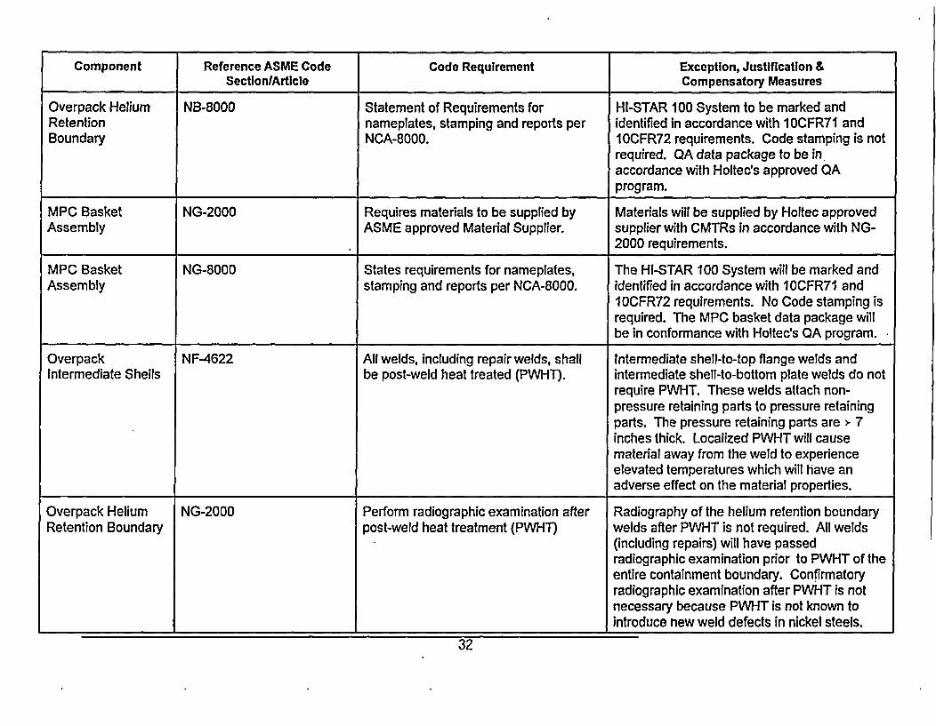
Component Reference ASME Code Code Requirement Exception, Justification &Section/Article Compensatory Measures
Overpack Helium NB-8000 Statement of Requirements for HI-STAR 100 System to be marked andRetention nameplates, stamping and reports per identified in accordance with 10CFR71 andBoundary NCA-8000. IOCFR72 requirements. Code stamping is not
required. QA data package to be inaccordance with Holtec's approved QAprogram.
MPC Basket NG-2000 Requires materials to be supplied by Materials will be supplied by Holtec approvedAssembly ASME approved Material Supplier. supplier with CMTRs in accordance with NG-
2000 requirements.
MPC Basket NG-8000 States requirements for nameplates, The HI-STAR 100 System will be marked andAssembly stamping and reports per NCA-8000. identified in accordance with 1OCFR71 and
I OCFR72 requirements. No Code stamping isrequired. The MPC basket data package willbe in conformance with Holtec's QA program.
Overpack NF-4622 All welds, including repair welds, shall Intermediate shell-to-top flange welds andIntermediate Shells be post-weld heat treated (PWHT). intermediate shell-to-bottom plate welds do not
require PWHT. These welds attach non-pressure retaining parts to pressure retainingparts. The pressure retaining parts are > 7inches thick. Localized PWHT will causematerial away from the weld to experienceelevated temperatures which will have anadverse effect on the material properties.
Overpack Helium NG-2000 Perform radiographic examination after Radiography of the helium retention boundaryRetention Boundary post-weld heat treatment (PWHT) welds after PWHT is not required. All welds
(including repairs) will have passedradiographic examination prior to PWHT of theentire containment boundary. Confirmatoryradiographic examination after PWHT is notnecessary because PWHT is not known tointroduce new weld defects in nickel steels.
32
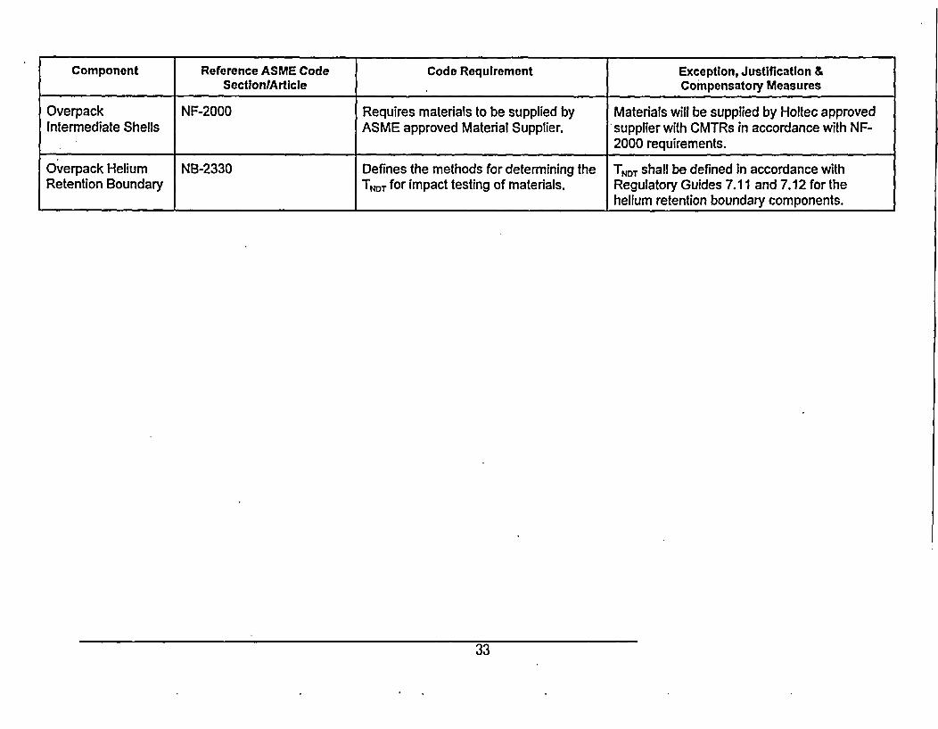
Component Reference ASME Code Code Requirement Exception, Justification &Section/Article Compensatory Measures
Overpack NF-2000 Requires materials to be supplied by Materials will be supplied by Holtec approvedIntermediate Shells ASME approved Material Supplier. supplier with CMTRs in accordance with NF-
2000 requirements.
Overpack Helium NB-2330 Defines the methods for determining the TNDT shall be defined in accordance withRetention Boundary TNDT for impact testing of materials. Regulatory Guides 7.11 and 7.12 for the
helium retention boundary components.
33