Centroid Hardinge Retrofit Manual...3 Revisions on 11/04/04 T:\DOCS\Hardinge\Centroid Hardinge...
62
CENTROID Retrofit Of Hardinge Lathe Procedure Manual Rev. 041104 © 2004 Centroid Corp. Howard, PA 16841
Transcript of Centroid Hardinge Retrofit Manual...3 Revisions on 11/04/04 T:\DOCS\Hardinge\Centroid Hardinge...

CENTROID RetrofitOf Hardinge Lathe
Procedure Manual
Rev. 041104
© 2004 Centroid Corp. Howard, PA 16841

1Revisions on 11/04/04 T:\DOCS\Hardinge\Centroid Hardinge Retrofit Manual.pmd
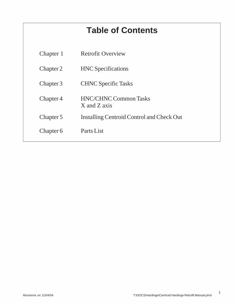
Table of Contents
Chapter 1 Retrofit Overview
Chapter 2 HNC Specifications
Chapter 3 CHNC Specific Tasks
Chapter 4 HNC/CHNC Common TasksX and Z axis
Chapter 5 Installing Centroid Control and Check Out
Chapter 6 Parts List
2Revisions on 11/04/04 T:\DOCS\Hardinge\Centroid Hardinge Retrofit Manual.pmd
Chapter 1
Retrofit Overview
1.1 HNC and CHNC Retrofit Overview
1.2 Lists of Retrofit Steps

3Revisions on 11/04/04 T:\DOCS\Hardinge\Centroid Hardinge Retrofit Manual.pmd
The first step of the Hardinge retrofit is the removal of the old control (may be Allen Bradley, GE etc.). Depending on which modelyou have (HNC or CHNC) first go to Chapter 1 HNC or Chapter 2 CHNC. When you have completed the HNC vs CHNC specific tasksgo to Chapter 4 to complete tasks common to both models.
HNC and CHNC Retrofit OverviewCentroid introduces the first total solution for completing a
retrofit on a Hardinge HNC or CHNC. No more long hours ofengineering and machining adapter plates for the encoders andspindle motors. Every wire location and terminal block is mappedout. There is a total pictorial guide to show how to retrofit stepby step. Within minutes you can be making money retrofittinginstead of inventing. There has never been a more precise andsimple manual to follow.
The control is auto loading ready, which streamlines installa-tion and saves using a complicated peripheral PLC. These mod-els of Hardinge machines come with the spindle headstock ma-chined for automation add on.
Features everything you need to retrofit a Hardinge CHNC orHNC:
Total SolutionSpindle Encoder & Retrofit adaptors includedSpindle Motor & plate, pulley and belt includedAnother Centroid first “total pictorial easy to followmanual”Auto loading Ready ControlRuns on Single Phase Power (option)Multiple AC voltage input 220/240/440/480 choicesMotor encoders and adaptors includedMotors and drives are matched for performanceThe entire turret PLC logic is provided
Figure 1.1.1 - Before
Figure 1.1.2 - After
Lists of Retrofit Steps The following is a list of the steps in a Hardinge retrofit:
1. Disconnect all wires going to the lathe frame.Remove the old control cabinet.
2. Remove the old magnetics cabinet, if present.Otherwise remove the old back panel assembliesfrom both end cabinets (HNC only).
3. Install the new terminal strips and connect the oldHardinge wires to the new terminal strips.
4. If the machine has the DC spindle drive, the old beltwill be reused. For the vari-drive spindle, removethe old spindle belt now. Cut the old belt. Or, if thecustomer wants to save the old belt, add additionallabor charges and remove the collet closer, the spin-dle feedback covers, the spindle feedback assembly,the spindle end covers, and the old spindle belt.
5. Remove the old spindle motor.6. Remove the vari-drive assembly, if present.7. Remove the motor mounting plate. Using the supplied
template, mark and drill the new spindle motor mountingholes.
8. Reinstall the spindle motor mounting plate.9. Remove the old spindle feedback system. It may be
necessary to remove the collet closer first, depending on model (mainly necessary with HNC models.)
10. Install the new spindle motor.11. If the unit has the vari-drive spindle, install the new
spindle drive belt. Remove the spindle end covers toinstall the new spindle drive belt. Reinstall the spindle endcovers, if they were removed.
12. Install the new spindle encoder. Reassemble the colletcloser, if the collet closer was removed.
HNC and CHNC Retrofit Overview 1.1
4Revisions on 11/04/04 T:\DOCS\Hardinge\Centroid Hardinge Retrofit Manual.pmd
13.Remove the X axis feedback assembly.14.If replacing the servo motors, remove the old X axis servo
motor now.15.If replacing the servo motors, install the new X axis servo
motor.16.If replacing the servo motors, wire the new X axis servo
motor.17. Install the new X axis encoder18.Remove the Z axis feedback assembly.19.If replacing the servo motors, remove the old Z axis servo
motor now.20.If replacing the servo motors, install the new Z axis servo
motor.21.If replacing the servo motors, wire the new Z axis servo
motor.22.Install the new Z axis encoder.23.Check all splices, heat shrink tubing, cable routing and
cable ties, etc.24.Connect the new control wires to the new terminal strips,
TB3-TB7.25.Test the new system:
Limit switchesAxis joggingSpindleTurretCollet closerCutoff tool, if presentParts chute, if presentDoor interlock(s)Program testThreading test
26.Check all splices, heat shrink tubing, cable routing andcable ties, etc.
27.Reinstall all remaining covers.28.Train the customer.29.Collect the check.
1.2 List of Retrofit Steps
5Revisions on 11/04/04 T:\DOCS\Hardinge\Centroid Hardinge Retrofit Manual.pmd
Chapter 2
HNC Specific TasksThis chapter applies only to HNC models. If you have a Hardinge CHNC, go to Chapter 3.
2.1 Removal Electric Cabinet and subpanel in Magnetic Cabinets
2.2 Prepping Hardinge Magnetic Cabinets
2.3 Removal of old spindle motor and vari-drive unit
2.4 Installing new A.C. spindle motor
2.5 Removal of Feedback Unit
2.6 Disassembly of Feedback Unit
2.7 Assembly of new spindle encoder
2.8 Installing new spindle encoder

6Revisions on 11/04/04 T:\DOCS\Hardinge\Centroid Hardinge Retrofit Manual.pmd
2.1 Removal of electrical cabinet and subpanels in magnetic cabinet
Cable B
Cable C
Cable A
Figure 2.1.1
Figure 2.1.2
Before removing conduit cables A, B & C (Figure 2.1.2), makesure all wires are labeled and the labels are secured. Only removeconduit cables A, B & C from the G.E. control cabinet going to theLathe (Figure 2.1.1). The wires in conduit cables A, B & C will beused, the G.E. control cabinet will not.
Figure 2.1.3
GroundWire
At the tailstock end of the lathe, remove the wires from the bot-tom side of the terminal block for reuse. Disconnect the coolantpump power and ground wires leaving them as long as possible.Also disconnect the ground wire for reuse (Figure 2.1.3). Re-move the subpanel assembly. Subpanel will not be reused.
TerminalBlock
Warning!! Do Not Randomly cut wires !!some need to be as long as possi-
ble for it will be used again.
7Revisions on 11/04/04 T:\DOCS\Hardinge\Centroid Hardinge Retrofit Manual.pmd
Removal of electrical cabinet and subpanels in magnetic cabinets 2.1
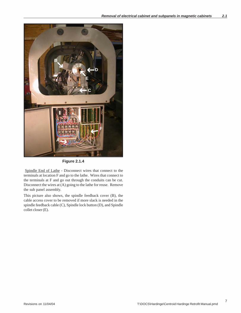
Spindle End of Lathe - Disconnect wires that connect to theterminals at location F and go to the lathe. Wires that connect tothe terminals at F and go out through the conduits can be cut.Disconnect the wires at (A) going to the lathe for reuse. Removethe sub panel assembly.This picture also shows, the spindle feedback cover (B), thecable access cover to be removed if more slack is needed in thespindle feedback cable (C), Spindle lock button (D), and Spindlecollet closer (E).
Figure 2.1.4
B
C
D
E
A
F
8Revisions on 11/04/04 T:\DOCS\Hardinge\Centroid Hardinge Retrofit Manual.pmd
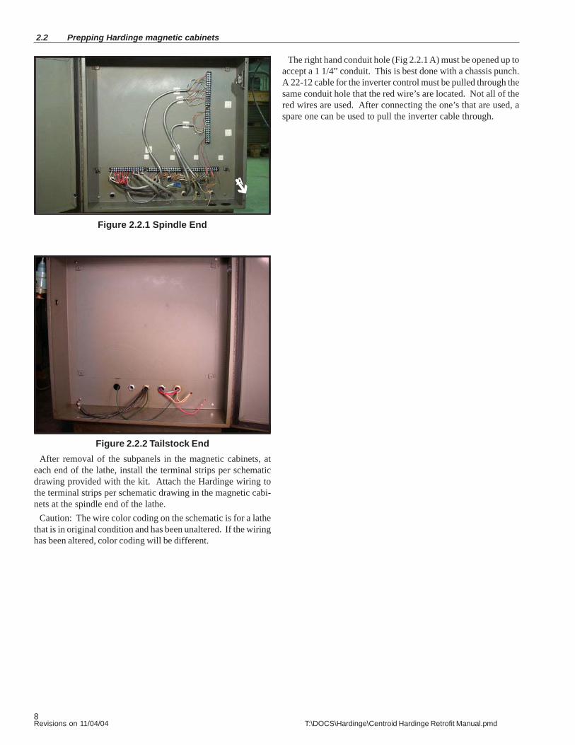
2.2 Prepping Hardinge magnetic cabinets
Figure 2.2.1 Spindle End
Figure 2.2.2 Tailstock EndAfter removal of the subpanels in the magnetic cabinets, at
each end of the lathe, install the terminal strips per schematicdrawing provided with the kit. Attach the Hardinge wiring tothe terminal strips per schematic drawing in the magnetic cabi-nets at the spindle end of the lathe.
Caution: The wire color coding on the schematic is for a lathethat is in original condition and has been unaltered. If the wiringhas been altered, color coding will be different.
A
The right hand conduit hole (Fig 2.2.1 A) must be opened up toaccept a 1 1/4” conduit. This is best done with a chassis punch.A 22-12 cable for the inverter control must be pulled through thesame conduit hole that the red wire’s are located. Not all of thered wires are used. After connecting the one’s that are used, aspare one can be used to pull the inverter cable through.

9Revisions on 11/04/04 T:\DOCS\Hardinge\Centroid Hardinge Retrofit Manual.pmd
Removal of old spindle motor and vari-drive unit 2.3
Figure 2.3.1 Remove the old spindle motor belt and the vari-drive belt bycutting the belt. To remove the belts without cutting, thread itover the spindle pulley and around the end of the vari-speedpulley shaft, then remove the spindle belt from the spindle. SeeFigures 2.5.6 through 2.5.8 for instructions to remove belt with-out cutting and installing new belt from the spindle.
Figure 2.3.2
At the front of the lathe, unwire the spindle motor. Remove thenuts from the two front side jack bolts at the front of the lathe(Figure 2.3.2 - A). After the spindle motor mounting plate isremoved, there are (2) nuts on the bottom side that need to beremoved.
Figure 2.3.3 At the back side of the lathe loosen the (2) bolts (Figure 2.3.3 -A) on the side of the motor mounting plate that are for the level-ers. Loosen the two top nuts (B) on the levelers and remove thetwo square plates underneath (B). Remove the center lock nut(C) and screw the jack bolt out to raise the plate up.
Figure 2.3.4
Block up the motor base plate. Remove the two bolts (Figure2.3.4 - A) holding the center jack plate, lower the jack bolt, andremove the jack bolt assembly (see Figure 2.3.5 - B).
A
BC B
A
AA
A
10Revisions on 11/04/04 T:\DOCS\Hardinge\Centroid Hardinge Retrofit Manual.pmd
2.3 Removal of old spindle motor and vari-drive unit
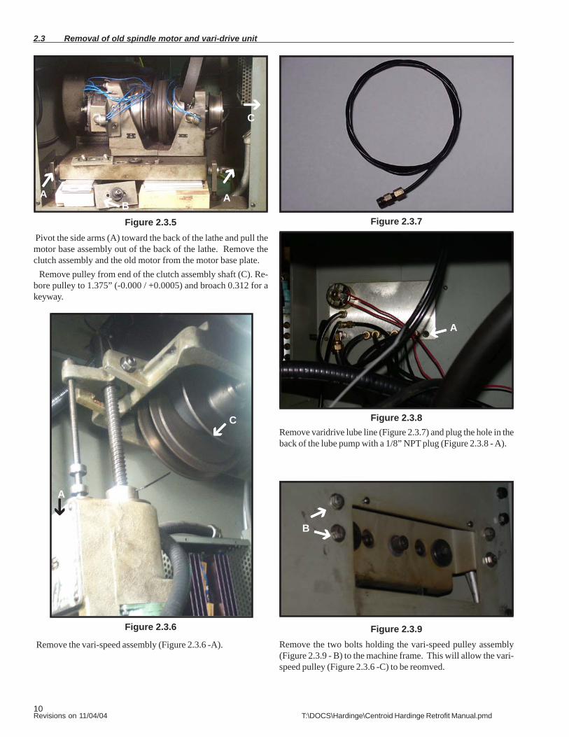
Figure 2.3.5 Pivot the side arms (A) toward the back of the lathe and pull themotor base assembly out of the back of the lathe. Remove theclutch assembly and the old motor from the motor base plate.
Remove pulley from end of the clutch assembly shaft (C). Re-bore pulley to 1.375” (-0.000 / +0.0005) and broach 0.312 for akeyway.
Figure 2.3.6
Remove the vari-speed assembly (Figure 2.3.6 -A).
AB
A
A
CRemove varidrive lube line (Figure 2.3.7) and plug the hole in theback of the lube pump with a 1/8” NPT plug (Figure 2.3.8 - A).
Figure 2.3.7
Figure 2.3.8
A
Figure 2.3.9
C
B
Remove the two bolts holding the vari-speed pulley assembly(Figure 2.3.9 - B) to the machine frame. This will allow the vari-speed pulley (Figure 2.3.6 -C) to be reomved.

11Revisions on 11/04/04 T:\DOCS\Hardinge\Centroid Hardinge Retrofit Manual.pmd
Installing the A.C. Spindle Motor 2.4
Figure 2.4.1
Remove the motor mounting plate then drill and tap the motormounting plate with the supplied template for 3/8-16 X 4 S.H.C.screws.
Remove the bottom nuts from the front 2 leveler bolts (Figure2.4.1 -A). You will only reuse the washers. Reinstall center jackbolt assembly (Figure 2.4.1 - B). Reinstall the 2 rear side levelerbolts and washers (C). Remove the blocking that was put inearlier when the motor was being removed. Install the motormounting plate. Mount the new motor to the motor base plate.Connect the spindle motor cable to the motor before installing itin the lathe (Figure 2.4.1 - D).
Installing new belt can be done after the removal of the feed-back unit (See Figures 2.5.1 through 2.5.5).
Feed the new spindle belt in from the top, over the spindlepulley (See Figure 2.5.8). Install the rebored motor pulley (fromsection 2.3.5) and belt, tighten to the proper tension.
A
B CC
D
12Revisions on 11/04/04 T:\DOCS\Hardinge\Centroid Hardinge Retrofit Manual.pmd
2.5 Removal of Feedback Unit
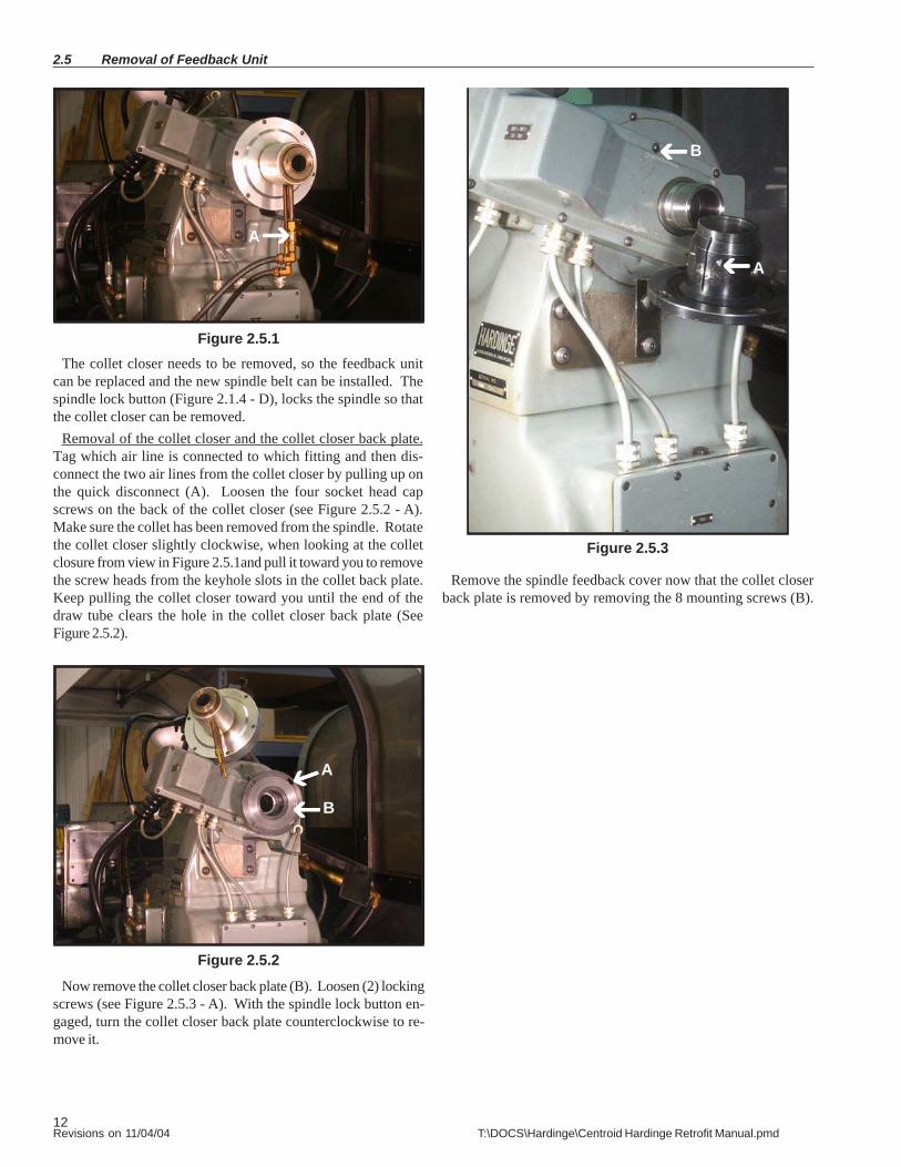
Figure 2.5.1The collet closer needs to be removed, so the feedback unit
can be replaced and the new spindle belt can be installed. Thespindle lock button (Figure 2.1.4 - D), locks the spindle so thatthe collet closer can be removed.
Removal of the collet closer and the collet closer back plate.Tag which air line is connected to which fitting and then dis-connect the two air lines from the collet closer by pulling up onthe quick disconnect (A). Loosen the four socket head capscrews on the back of the collet closer (see Figure 2.5.2 - A).Make sure the collet has been removed from the spindle. Rotatethe collet closer slightly clockwise, when looking at the colletclosure from view in Figure 2.5.1and pull it toward you to removethe screw heads from the keyhole slots in the collet back plate.Keep pulling the collet closer toward you until the end of thedraw tube clears the hole in the collet closer back plate (SeeFigure 2.5.2).
A
Remove the spindle feedback cover now that the collet closerback plate is removed by removing the 8 mounting screws (B).
Figure 2.5.3
Now remove the collet closer back plate (B). Loosen (2) lockingscrews (see Figure 2.5.3 - A). With the spindle lock button en-gaged, turn the collet closer back plate counterclockwise to re-move it.
Figure 2.5.2
A
B
A
B
13Revisions on 11/04/04 T:\DOCS\Hardinge\Centroid Hardinge Retrofit Manual.pmd
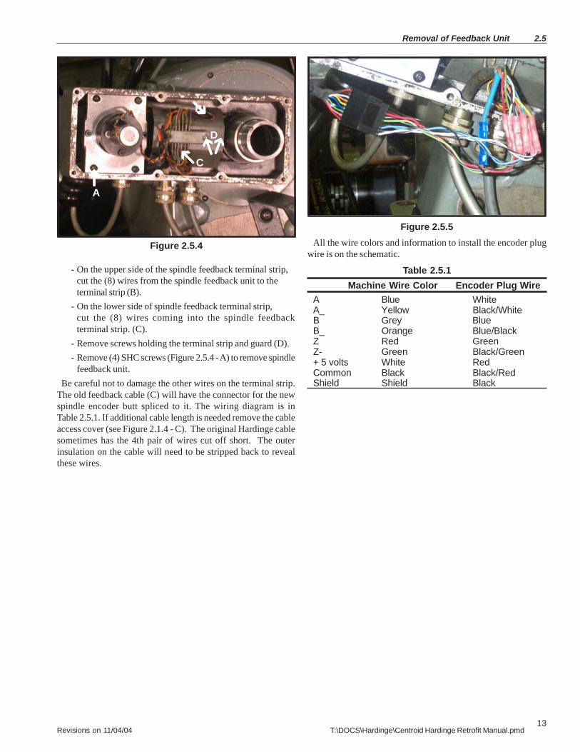
Figure 2.5.5All the wire colors and information to install the encoder plug
wire is on the schematic.
Table 2.5.1Machine Wire Color Encoder Plug Wire
A Blue WhiteA_ Yellow Black/WhiteB Grey BlueB_ Orange Blue/BlackZ Red GreenZ- Green Black/Green+ 5 volts White RedCommon Black Black/RedShield Shield Black
Removal of Feedback Unit 2.5
Figure 2.5.4
- On the upper side of the spindle feedback terminal strip,cut the (8) wires from the spindle feedback unit to theterminal strip (B).
- On the lower side of spindle feedback terminal strip,cut the (8) wires coming into the spindle feedbackterminal strip. (C).
- Remove screws holding the terminal strip and guard (D).- Remove (4) SHC screws (Figure 2.5.4 - A) to remove spindle
feedback unit. Be careful not to damage the other wires on the terminal strip.The old feedback cable (C) will have the connector for the newspindle encoder butt spliced to it. The wiring diagram is inTable 2.5.1. If additional cable length is needed remove the cableaccess cover (see Figure 2.1.4 - C). The original Hardinge cablesometimes has the 4th pair of wires cut off short. The outerinsulation on the cable will need to be stripped back to revealthese wires.
B
C
A
D
14Revisions on 11/04/04 T:\DOCS\Hardinge\Centroid Hardinge Retrofit Manual.pmd
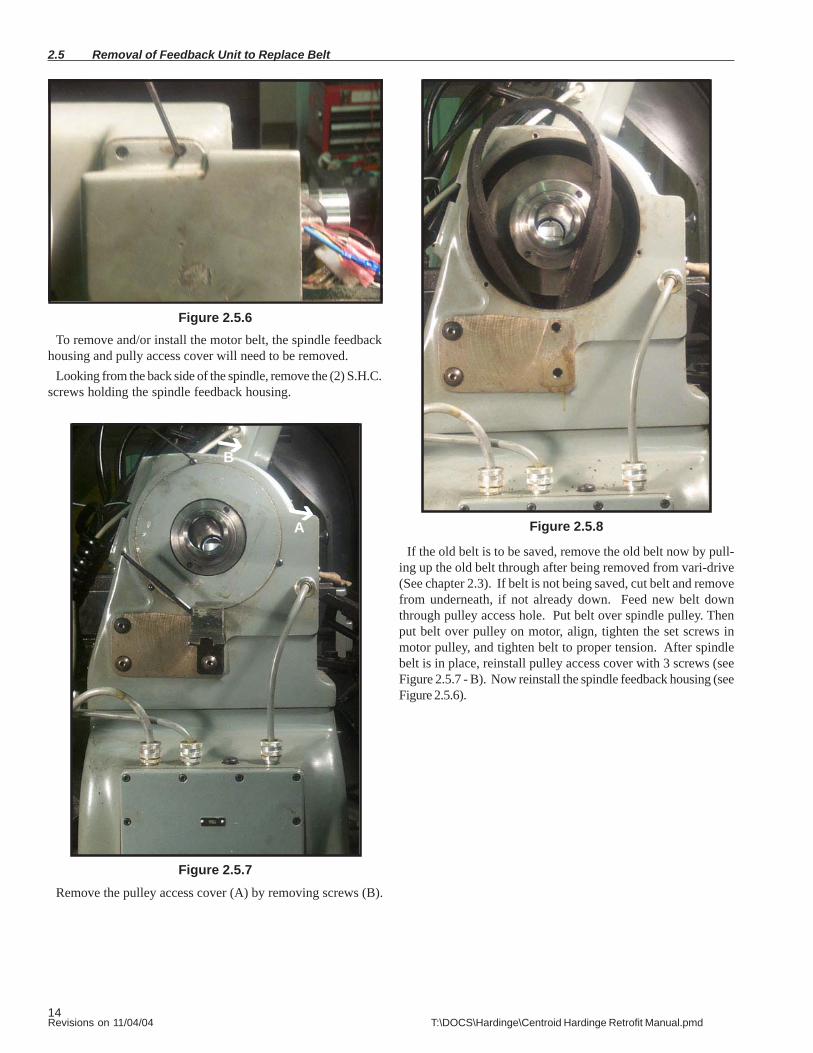
2.5 Removal of Feedback Unit to Replace Belt
Figure 2.5.6To remove and/or install the motor belt, the spindle feedback
housing and pully access cover will need to be removed.Looking from the back side of the spindle, remove the (2) S.H.C.
screws holding the spindle feedback housing.
Figure 2.5.7Remove the pulley access cover (A) by removing screws (B).
Figure 2.5.8
If the old belt is to be saved, remove the old belt now by pull-ing up the old belt through after being removed from vari-drive(See chapter 2.3). If belt is not being saved, cut belt and removefrom underneath, if not already down. Feed new belt downthrough pulley access hole. Put belt over spindle pulley. Thenput belt over pulley on motor, align, tighten the set screws inmotor pulley, and tighten belt to proper tension. After spindlebelt is in place, reinstall pulley access cover with 3 screws (seeFigure 2.5.7 - B). Now reinstall the spindle feedback housing (seeFigure 2.5.6).
A
B

15Revisions on 11/04/04 T:\DOCS\Hardinge\Centroid Hardinge Retrofit Manual.pmd
Disassembly of Feedback Unit 2.6
Figure 2.6.1As shown in Figure 2.6.1, loosen (2) set screws on each end of
the (2) couplers (A) (8 set screws total between (2) couplers).Next remove (2) S.H.C. screws (B). Feedback unit will come apartat (C). Now you have access to S.H.C. screws (D). RemoveS.H.C. screws and discard Feedback unit (E) and coupler. Re-move S.H.C. screws (F) and then discard encoder (G) and cou-pler.
A
B
C
A
D EFG
Figure 2.6.2
A
Once the coupler is removed, the pulley shaft can be removedfrom the mounting block. Remove the shaft nut (Figure 2.6.2 - A)by turning counterclockwise, and pull the shaft out of the pulleyand bearings. Retain the pulley, 2 bearings, nut, and springwasher for reuse with the new shaft and new encoder. Discardold pulley shaft.

16Revisions on 11/04/04 T:\DOCS\Hardinge\Centroid Hardinge Retrofit Manual.pmd
2.7 Assembly of new spindle encoder
Figure 2.7.1
A
B
CD E
F
Install bearing (A) on new pulley shaft up against shoulder onnew shaft. Next install pulley (B) in the shaft. Install bearing(C) then tighten nut (D) into shaft. Install spring wash (E) be-fore pressing shaft assemble into Housing (F).
Figure 2.7.2Assemble the attach mounting block to the encoder bearing
block, reusing the two allen bolts (B). Caution: the belt is onlyunder 1 leg of the assembly and is actually around the other leg(see figure 2.6.1). Make sure the encoder belt (A) is in the placeon the pulley before assembly. Mount the encoder on the end ofthe new encoder shaft. Tighten the set screws in shaft couplingand mark the encoder mounting hole location.
B
A
Figure 2.7.3Remove the encoder. Center punch the hole, then drill (#35)
and tap for a 6-32 machine screw. DO NOT CENTER PUNCHHOLE WHILE ENCODER IS MOUNTED. The shock coulddamage encoder.
Figure 2.7.4
Remount the new encoder to the shaft. Tighten the (2) setscrews (A) on the encoder to the shaft coupling, then install the6-32 screw (B) in the new mounting hole.
BA
17Revisions on 11/04/04 T:\DOCS\Hardinge\Centroid Hardinge Retrofit Manual.pmd
Installing new spindle encoder 2.8
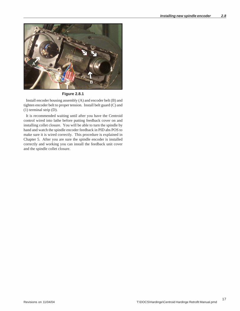
Figure 2.8.1Install encoder housing assembly (A) and encoder belt (B) and
tighten encoder belt to proper tension. Install belt guard (C) and(1) terminal strip (D).
It is recommended waiting until after you have the Centroidcontrol wired into lathe before putting feedback cover on andinstalling collet closure. You will be able to turn the spindle byhand and watch the spindle encoder feedback in PID abs POS tomake sure it is wired correctly. This procedure is explained inChapter 5. After you are sure the spindle encoder is installedcorrectly and working you can install the feedback unit coverand the spindle collet closure.
A
B
CD
18Revisions on 11/04/04 T:\DOCS\Hardinge\Centroid Hardinge Retrofit Manual.pmd
Chapter 3
CHNC Specific TasksThis chapter applies only to CHNC models. If you have a Hardinge HNC, go to Chapter 2.
3.1 Removal Control Cabinet and Magnetic Cabinet
3.2 Prepping CHNC Magnetic Cabinet
3.3 Removal of D.C. spindle motor
3.4 Installing new A.C. spindle motor
3.5 Removal of Feedback Unit
3.6 Disassembly of Feedback Unit
3.7 Assembly of new spindle encoder
3.8 Installing new spindle belt
3.9 Installing new spindle encoder

19Revisions on 11/04/04 T:\DOCS\Hardinge\Centroid Hardinge Retrofit Manual.pmd
Removal of Control Cabinet and Magnetic Cabinet 3.1
Figure 3.1.1Open the lid on top of the wire race way (A). Pull the wires
from the control cabinet through the race way and into the mag-netic cabinet. Remove the empty race way. The wires can be cutat the top of the interconnect cabinet, but you will need to checkthe cables with a meter to determine what they connect to.
MagneticCabinet Control
Cabinet
InterconnectCabinet
Figure 3.1.2
All cables that go through the interconnect cabinet (A) must beunlaced so the magnetic cabinet can be removed. Make sure allcables have labels before they are disconnected. Remove themagnetic cabinet.
Note: Before you remove the bolts that hold themagnetic cabinet make sure you block the magneticcabinet up and support it properly. The magneticcabinet is held only by these (10) bolts.
A
Figure 3.1.3This is what your machine should look like after you have
removed the old control. This view displays all the wires to bereused.
InterconnectCabinet
A
20Revisions on 11/04/04 T:\DOCS\Hardinge\Centroid Hardinge Retrofit Manual.pmd
3.2 Prepping CHNC Magnetic Cabinet
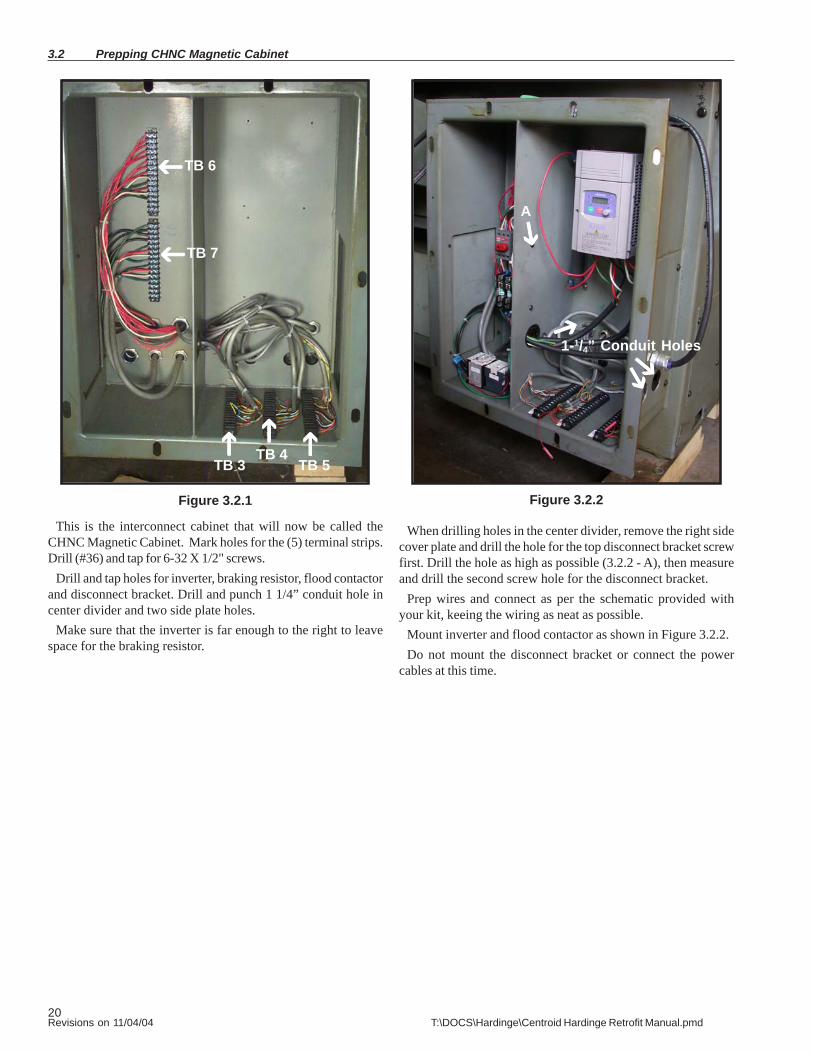
Figure 3.2.1
This is the interconnect cabinet that will now be called theCHNC Magnetic Cabinet. Mark holes for the (5) terminal strips.Drill (#36) and tap for 6-32 X 1/2" screws.
Drill and tap holes for inverter, braking resistor, flood contactorand disconnect bracket. Drill and punch 1 1/4” conduit hole incenter divider and two side plate holes.
Make sure that the inverter is far enough to the right to leavespace for the braking resistor.
TB 6
TB 7
TB 3TB 4
TB 5
Figure 3.2.2
1-1/4” Conduit Holes
When drilling holes in the center divider, remove the right sidecover plate and drill the hole for the top disconnect bracket screwfirst. Drill the hole as high as possible (3.2.2 - A), then measureand drill the second screw hole for the disconnect bracket.
Prep wires and connect as per the schematic provided withyour kit, keeing the wiring as neat as possible.
Mount inverter and flood contactor as shown in Figure 3.2.2.Do not mount the disconnect bracket or connect the power
cables at this time.
A

21Revisions on 11/04/04 T:\DOCS\Hardinge\Centroid Hardinge Retrofit Manual.pmd
Removal of D.C. Spindle Motor 3.3
Figure 3.3.2
Before removing D.C. spindle motor, measure how far thepulley is from mounting plate (Figure 3.3.1 - A), so when themotor is reinstalled, it is easier to align the pulley. Loosen (2)bolts (Figure 3.3.1 - B) to remove pulley. Properly block motorbefore loosening the (4) bolts that hold the motor to the mount-ing plate. Unwire D.C. spindle motor. This motor is heavy, rec-ommend (2) people when removing to prevent injury. Save theplastic bushing and washers that the D.C. motor mounting boltsgo through. These are used to help align template that is used todrill the (4) 17/32 holes to mount the new A.C. motor and tomount the new A.C. motor.
Figure 3.3.3
After D.C. spindle motor is removed, mounting plate (A) hasto be removed to drill (4) 17/32 holes to mount new A.C. motor.Remove the (6) bolts (B) that hold the mounting plate to themounting bracket. Do not remove the adjusting bolts (C). Asshown in Figure 3.3.3, remove the lower 2 bolts at (D) level andthe front bolt at (E) level on each side. Next loosen the 4th bolton each of the mounting bracket at the back of (E) level. Do notremove these 2 bolts.
Figure 3.3.4
With the 4th bolt loose on each side of the mounting bracket,swing the mounting brackets down until mounting bracket restsat (Figure 3.3.4 - A). You may have to pry the brackets becausethere is a rubber gasket behind each mounting bracket. Once thebrackets are loose, remove the rubber gaskets and discard them.After you have swung the brackets down, remove the fourth bolton the right mounting bracket only.
AB
D D
AC E
B
A
C
Figure 3.3.1
CB
B
B
22Revisions on 11/04/04 T:\DOCS\Hardinge\Centroid Hardinge Retrofit Manual.pmd
3.3 Removal of D.C. Spindle Motor
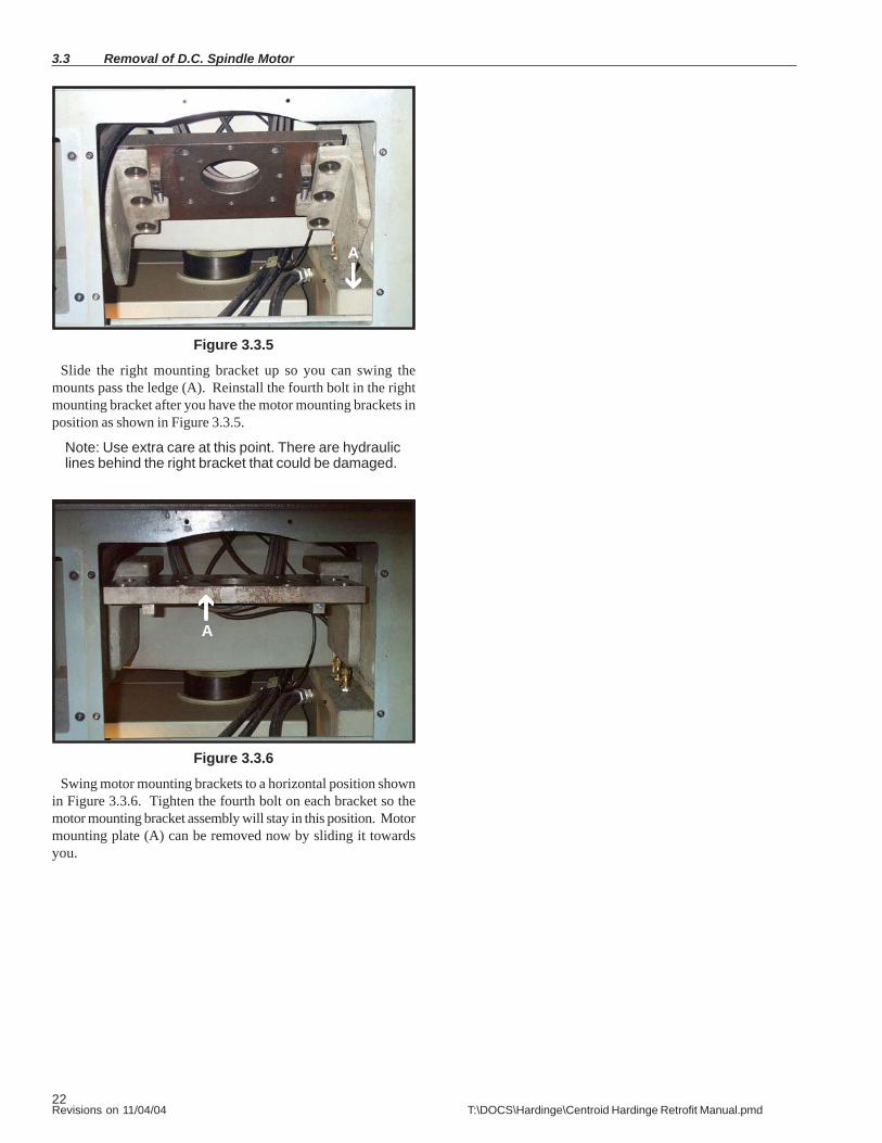
Figure 3.3.5
Slide the right mounting bracket up so you can swing themounts pass the ledge (A). Reinstall the fourth bolt in the rightmounting bracket after you have the motor mounting brackets inposition as shown in Figure 3.3.5.
Note: Use extra care at this point. There are hydrauliclines behind the right bracket that could be damaged.
Figure 3.3.6
Swing motor mounting brackets to a horizontal position shownin Figure 3.3.6. Tighten the fourth bolt on each bracket so themotor mounting bracket assembly will stay in this position. Motormounting plate (A) can be removed now by sliding it towardsyou.
A
A
23Revisions on 11/04/04 T:\DOCS\Hardinge\Centroid Hardinge Retrofit Manual.pmd
Installing new A.C. Spindle Motor 3.4
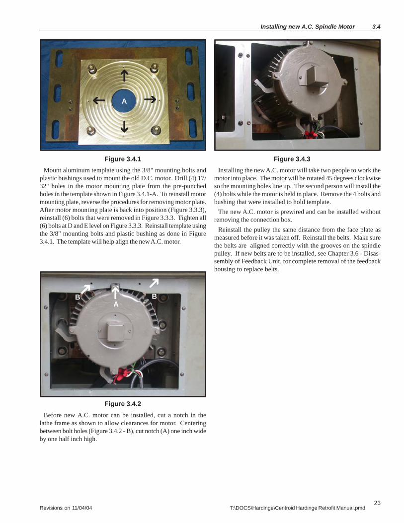
Figure 3.4.1Mount aluminum template using the 3/8" mounting bolts and
plastic bushings used to mount the old D.C. motor. Drill (4) 17/32" holes in the motor mounting plate from the pre-punchedholes in the template shown in Figure 3.4.1-A. To reinstall motormounting plate, reverse the procedures for removing motor plate.After motor mounting plate is back into position (Figure 3.3.3),reinstall (6) bolts that were removed in Figure 3.3.3. Tighten all(6) bolts at D and E level on Figure 3.3.3. Reinstall template usingthe 3/8" mounting bolts and plastic bushing as done in Figure3.4.1. The template will help align the new A.C. motor.
Figure 3.4.2Before new A.C. motor can be installed, cut a notch in the
lathe frame as shown to allow clearances for motor. Centeringbetween bolt holes (Figure 3.4.2 - B), cut notch (A) one inch wideby one half inch high.
Figure 3.4.3Installing the new A.C. motor will take two people to work the
motor into place. The motor will be rotated 45 degrees clockwiseso the mounting holes line up. The second person will install the(4) bolts while the motor is held in place. Remove the 4 bolts andbushing that were installed to hold template.
The new A.C. motor is prewired and can be installed withoutremoving the connection box.
Reinstall the pulley the same distance from the face plate asmeasured before it was taken off. Reinstall the belts. Make surethe belts are aligned correctly with the grooves on the spindlepulley. If new belts are to be installed, see Chapter 3.6 - Disas-sembly of Feedback Unit, for complete removal of the feedbackhousing to replace belts.
A
BA
B
24Revisions on 11/04/04 T:\DOCS\Hardinge\Centroid Hardinge Retrofit Manual.pmd
3.5 Removal of Feedback Unit on CHNC
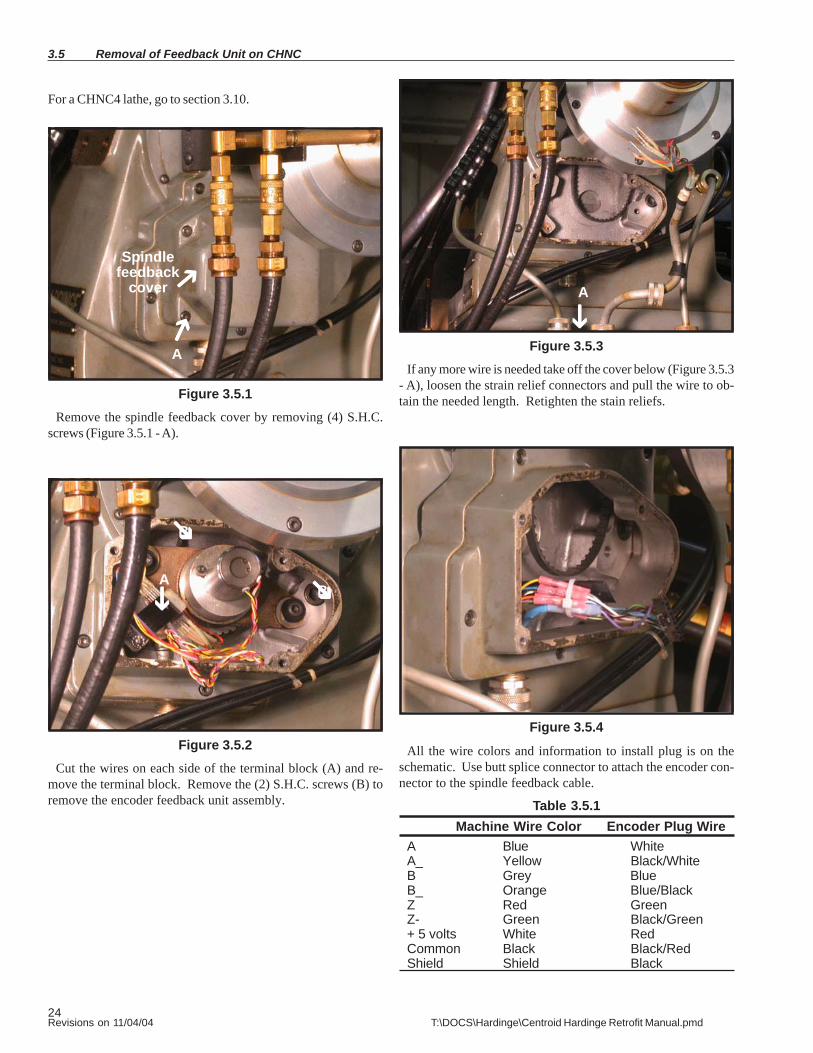
Figure 3.5.1Remove the spindle feedback cover by removing (4) S.H.C.
screws (Figure 3.5.1 - A).
A
Spindlefeedback
cover
Figure 3.5.2Cut the wires on each side of the terminal block (A) and re-
move the terminal block. Remove the (2) S.H.C. screws (B) toremove the encoder feedback unit assembly.
Figure 3.5.3If any more wire is needed take off the cover below (Figure 3.5.3
- A), loosen the strain relief connectors and pull the wire to ob-tain the needed length. Retighten the stain reliefs.
Figure 3.5.4
All the wire colors and information to install plug is on theschematic. Use butt splice connector to attach the encoder con-nector to the spindle feedback cable.
Table 3.5.1Machine Wire Color Encoder Plug Wire
A Blue WhiteA_ Yellow Black/WhiteB Grey BlueB_ Orange Blue/BlackZ Red GreenZ- Green Black/Green+ 5 volts White RedCommon Black Black/RedShield Shield Black
BA
A
B
For a CHNC4 lathe, go to section 3.10.
25Revisions on 11/04/04 T:\DOCS\Hardinge\Centroid Hardinge Retrofit Manual.pmd
A
A
B
Disassembly of Feedback Unit 3.6
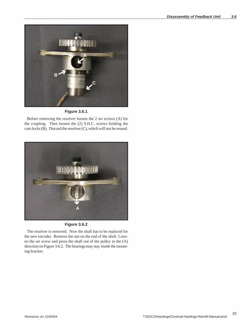
Figure 3.6.1Before removing the resolver loosen the 2 set screws (A) for
the coupling. Then loosen the (2) S.H.C. screws holding thecam locks (B). Discard the resolver (C), which will not be reused.
Figure 3.6.2The resolver is removed. Now the shaft has to be replaced for
the new encoder. Remove the nut on the end of the shaft. Loos-en the set screw and press the shaft out of the pulley in the (A)direction on Figure 3.6.2. The bearings may stay inside the mount-ing bracket.
C

26Revisions on 11/04/04 T:\DOCS\Hardinge\Centroid Hardinge Retrofit Manual.pmd
Reused
Newscrews
New Encoder
New Shaft
New Encoder spacer mount
Reused
3.7 Assembly of new spindle encoder
Figure 3.7.1This is a view of the new encoder, new shaft, new spacer, 3
new screws, and parts that are being reused.
Figure 3.7.2
If bearings have been removed, reinstall the bearings in bear-ing block. Install the new shaft into bearing block. Install pul-ley, align set screw with flat, lightly tighten set screw, tightennut, and tighten set screw. Install new encoder mounting platewith 6-32 flat head screw. Install encoder and align 2 set screwswith flats on shaft, put encoder into position, tighten (2) setscrews, and install 6-32 encoder mounting screw.
Figure 3.7.3New encoder mounted on the Feedback bearing block.
NutReused
PulleyReused
BearingBlock
Reused
NewShaft
NewEncoderMounting
Plate
NewEncoder

27Revisions on 11/04/04 T:\DOCS\Hardinge\Centroid Hardinge Retrofit Manual.pmd
Installing new spindle belt 3.8
Figure 3.8.1
Collet closer (Figure 3.8.1 - A) and feedback cover (B), andfeedback housing (C) have to be removed to remove the coverplate (D) to get to the spindle belts. Mark air lines (E) beforeremoving, push the lock pin so the spindle will not turn. To re-move collet closure, see chapter 2.5, figures 2.5.1, 2.5.2 and 2.5.3.If feedback unit has not already been removed see Chapter 3.5.
Figure 3.8.2
Remove (6) S.H.C. screws (3.8.1 -F) from the middle feedbackhousing. Remove feedback unit belt. Remove (3) S.H.C. screwsto remove housing. Remove (3) S.H.C. screws (Figure 3.8.2 - A) toremove cover plate. Remove old belts and feed new belts downthrough. Align belts on spindle pulley and motor pulley. Tightenbelts to proper tension. Reverse the above procedures to reas-semble.
D
A
B
E
A
A AC
F
28Revisions on 11/04/04 T:\DOCS\Hardinge\Centroid Hardinge Retrofit Manual.pmd
3.9 Installing new spindle encoder
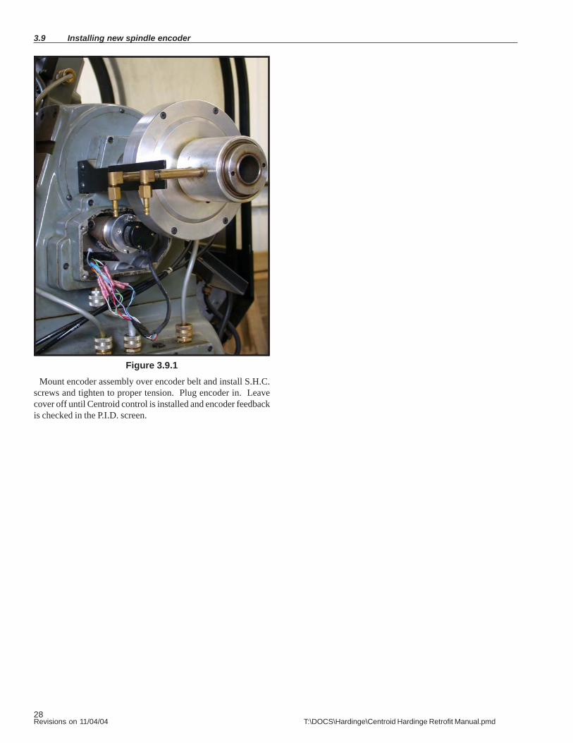
Figure 3.9.1Mount encoder assembly over encoder belt and install S.H.C.
screws and tighten to proper tension. Plug encoder in. Leavecover off until Centroid control is installed and encoder feedbackis checked in the P.I.D. screen.
29Revisions on 11/04/04 T:\DOCS\Hardinge\Centroid Hardinge Retrofit Manual.pmd
Installing new spindle encoder for CHNC4 3.10
1. Remove encoder mount, two screws, pivot and adjustment2. encoder wires done the same as the CHNC ... see Section 3.5,figures 3.5.2, 3.5.3 and 3.5.43. Loosen coupler and remove old resolver.4. Remove spanner nut. Loosen set screw on pulley. Push oldshaft out. Replace with new shaft. Tighten spanner nut and pul-ley set screw.5. Place encoder in position on shaft and mark the location of themounting hole. Remove the encoder.6. Drill and tap 1 6-32 hole. Be sure to protect the bearings frommetal chips.7. Install encoder.
30Revisions on 11/04/04 T:\DOCS\Hardinge\Centroid Hardinge Retrofit Manual.pmd
Chapter 4
HNC/CHNC Common Tasks
4.1 X axis encoder
4.2 Z axis encoder
4.3 X axis motor
4.4 Z axis motor
31Revisions on 11/04/04 T:\DOCS\Hardinge\Centroid Hardinge Retrofit Manual.pmd
4.1 X axis encoder
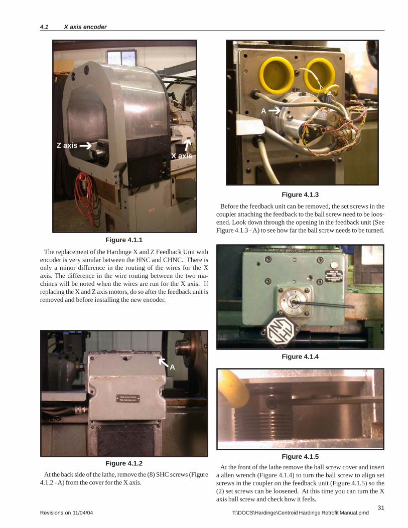
Figure 4.1.1
X axisZ axis
The replacement of the Hardinge X and Z Feedback Unit withencoder is very similar between the HNC and CHNC. There isonly a minor difference in the routing of the wires for the Xaxis. The difference in the wire routing between the two ma-chines will be noted when the wires are run for the X axis. Ifreplacing the X and Z axis motors, do so after the feedback unit isremoved and before installing the new encoder.
At the back side of the lathe, remove the (8) SHC screws (Figure4.1.2 - A) from the cover for the X axis.
Figure 4.1.2
A
Figure 4.1.3Before the feedback unit can be removed, the set screws in the
coupler attaching the feedback to the ball screw need to be loos-ened. Look down through the opening in the feedback unit (SeeFigure 4.1.3 - A) to see how far the ball screw needs to be turned.
Figure 4.1.4
At the front of the lathe remove the ball screw cover and inserta allen wrench (Figure 4.1.4) to turn the ball screw to align setscrews in the coupler on the feedback unit (Figure 4.1.5) so the(2) set screws can be loosened. At this time you can turn the Xaxis ball screw and check how it feels.
Figure 4.1.5
A
32Revisions on 11/04/04 T:\DOCS\Hardinge\Centroid Hardinge Retrofit Manual.pmd
X axis encoder 4.1
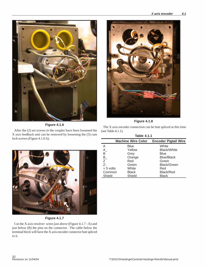
Figure 4.1.6After the (2) set screws in the coupler have been loosened the
X axis feedback unit can be removed by loosening the (3) camlock screws (Figure 4.1.6 A).
Figure 4.1.7Cut the X axis resolver wires just above (Figure 4.1.7 - A) and
just below (B) the pins on the connector. The cable below theterminal block will have the X axis encoder connector butt splicedto it.
A
B
Figure 4.1.8The X axis encoder connection can be butt spliced at this time
(see Table 4.1.1).Table 4.1.1
Machine Wire Color Encoder Pigtail WireA Blue WhiteA_ Yellow Black/WhiteB Grey BlueB_ Orange Blue/BlackZ Red GreenZ- Green Black/Green+ 5 volts White RedCommon Black Black/RedShield Shield Black
A

33Revisions on 11/04/04 T:\DOCS\Hardinge\Centroid Hardinge Retrofit Manual.pmd
4.1 X axis encoder
Figure 4.1.9Remove feedback assembly unit (A) and sensor (B) from mount-
ing plate (C) and discard feedback unit and sensor.
B
A
C
D
A
Figure 4.1.10
Reinstall mounting plate (Figure 4.1.9 - C) and slide encoderover the end of the ball screw until it is properly seated. Using amarker, mark the mounting slot (A). DO NOT USE A CENTERPUNCH TO MARK HOLE WHILE ENCODER IS IN PLACE. Re-move encoder and mounting plate. Center punch and drill (#36)and tap for a 6-32 screw in the center of the area marked earlier. IfX axis motor is being replaced, refer to Chapter 4, HNC/CHNCCommon Tasks 4.3.
Figure 4.1.11Reinstall the X encoder mounting plate to the back plate using
the 3 cam lock screws previously loosened. Put the new encod-er on the end of the ball screw shaft and loosely insert the 6-32screw. Align the encoder, then tighten the (2) set screws onto theball screw shaft, then tighten the 6-32 mounting screw for theencoder to the base plate. Plug the encoder connector into thenew connector that was butt spliced onto the existing X feed-back cable (Figure 4.1.8). Do not replace the feedback coversuntil proper axis motion has been verified.
34Revisions on 11/04/04 T:\DOCS\Hardinge\Centroid Hardinge Retrofit Manual.pmd
Z axis encoder 4.2
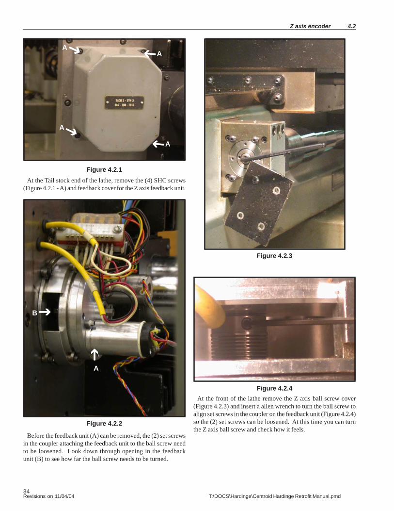
Figure 4.2.1At the Tail stock end of the lathe, remove the (4) SHC screws
(Figure 4.2.1 - A) and feedback cover for the Z axis feedback unit.
Figure 4.2.2
Figure 4.2.3
At the front of the lathe remove the Z axis ball screw cover(Figure 4.2.3) and insert a allen wrench to turn the ball screw toalign set screws in the coupler on the feedback unit (Figure 4.2.4)so the (2) set screws can be loosened. At this time you can turnthe Z axis ball screw and check how it feels.
Figure 4.2.4
Before the feedback unit (A) can be removed, the (2) set screwsin the coupler attaching the feedback unit to the ball screw needto be loosened. Look down through opening in the feedbackunit (B) to see how far the ball screw needs to be turned.
A
AA
A
A
B

35Revisions on 11/04/04 T:\DOCS\Hardinge\Centroid Hardinge Retrofit Manual.pmd
Figure 4.2.5
After the (2) set screws in the coupler have been loosened theZ axis feedback unit can be removed by loosening the (4) camlock screws (Figure 4.2.5 - A).
Cut the Z axis resolver wires just above (A) and just below (B)the pins on the connector. The cable (C) that was attached to theterminal block will have the Z axis encoder connector butt splicedto it.
B
Figure 4.2.6
The Z axis encoder connection can be butt-splitted at this time(see Table 4.2.1).
Table 4.2.1Machine Wire Color Encoder Pigtail Wire
A Blue WhiteA_ Yellow Black/WhiteB Grey BlueB_ Orange Blue/BlackZ Red GreenZ- Green Black/Green+ 5 volts White RedCommon Black Black/RedShield Shield Black
4.2 Z axis encoder
B
A
C
A

36Revisions on 11/04/04 T:\DOCS\Hardinge\Centroid Hardinge Retrofit Manual.pmd
Figure 4.2.7Remove feedback unit (A) and sensor (B) from mounting place
(C) and discard feedback unit and sensor.
B
A
C
D
A
Figure 4.2.8Reinstall mounting plate (Figure 4.2.7 - C) and slide encoder
over the end of the ball screw until it is properly seated. Using amarker, mark the mounting slot (A). DO NOT USE A CENTERPUNCH TO MARK HOLE WHILE ENCODER IS IN PLACE. Re-move encoder and mounting plate. Center punch, drill (#35) andtap for a 6-32 screw in the center of the area marked earlier. If Zaxis motor is being replaced, refer to Chapter 4, HNC/CHNC Com-mmon Tasks 4.4.
Figure 4.2.9Mount the Z encoder mounting plate to the back plate using
the 4 cam lock screws previously loosened. Put the new encoderon the end of the ball screw shaft and loosely insert the 6-32screw. Now tighten the (2) set screws onto the ball screw shaft,then tighten the 6-32 mounting screw for the encoder to the baseplate. Plug the encoder connector into the new connector thatwas butt spliced onto the existing Z feedback cable (Figure 4.2.6).Do not replace the feedback covers until proper axis motion hasbeen verified.
Z axis encoder 4.2

37Revisions on 11/04/04 T:\DOCS\Hardinge\Centroid Hardinge Retrofit Manual.pmd
4.3 X axis motor
If it is determined that the X axis motor needs to be replaced,this is to be done after the X feedback assembly is removed, andbefore the new encoder installation.
Figure 4.3.1
Remove the four X axis motor mounting bolts (A). Removethe old motor.
Figure 4.3.2
Remove the six bolts (A) and remove the X axis pulley accesscover.
Figure 4.3.3Cut the motor cable near the motor (A).
Figure 4.3.4Remove the X motor cable from the strain relief (A), then re-
move the stain relief and plug the hole with a 3/4 inch pipe plug.
A
A
A
A

38Revisions on 11/04/04 T:\DOCS\Hardinge\Centroid Hardinge Retrofit Manual.pmd
X axis motor 4.3
Figure 4.3.5
Remove the cable mounting cover (4 screws, see Figure 4.3.5 -A). Loosen the strain relief and pull the old motor cable out ofthe strain relief (Figure 4.3.6).
Figure 4.3.6
Figure 4.3.7Mount the new X motor to the adapter plate with 4 SHCS with
lock and flat washers. Mount the X adapter plate to the crossslide with 4 each 10-32 X 3/4 screws, 8 flat washers, 4 lockwashers, and 4 nuts (see Figure 4.3.7 or assembly drawing). In-stall the new X axis motor belt and pulley for 2-to-1 ratio, and setto proper tension.
Figure 4.3.8
Figure 4.3.9
On a HNC, route the new X motor cable through the strain relief(Figure 4.3.8 - A) in the cable mounting cover. Allow enoughslack for maximum Z-travel and tighten up the strain relief. Cabletie the cable under the cross slide or reinstall the cable wrap toprotect the cable. Before installing the cable mounting cover,drill a 7/8 inch hole in the cable mounting cover (Figure 4.3.9 - A)and install the strain relief for the Z motor cable. Z motor cablewill be installed later. After both X and Z axis have been testedthe cable mounting cover can be replaced.
On a CHNC, the X axis cable will be run through the caterpillartrack.
A
A
A
A
A

39Revisions on 11/04/04 T:\DOCS\Hardinge\Centroid Hardinge Retrofit Manual.pmd
4.3 X axis motor
Figure 4.3.10Cut the new cable to length under the machine, if necessary.
Put heat shrink tubing over the cable and butt splice the newcable to the old X motor cable (Figure 4.3.10). Test the servomotor before shrinking the heat shrink tubing.

40Revisions on 11/04/04 T:\DOCS\Hardinge\Centroid Hardinge Retrofit Manual.pmd
Z axis motor 4.4
If it is determined that the Z axis motor needs to be replaced thisis to be done after Z feedback assembly removal, and beforenew encoder installation.
Figure 4.4.1Remove (4) S.H.C. screws that hold the Z axis motor and Z
axis heat sink. The (4) screws are down in the heat sink fins(Figure 4.4.1 - A).
Figure 4.4.2Cut the motor cable near the motor (A).
Figure 4.4.3
Loosen the strain relief, pull the old Z motor cable down underthe machine frame and retighten the strain relief. The Z axismotor cable will not be fed through this strain relief.
AA

41Revisions on 11/04/04 T:\DOCS\Hardinge\Centroid Hardinge Retrofit Manual.pmd
Figure 4.4.6Cut the new cable to length under the machine, if necessary.
Put heat shrink tubing over the cable and butt splice the newcable to the old Z motor cable (Figure 4.4.6). Test the servo motorbefore shrinking the heat shrink tubing.
4.4 Z axis motor
Mount the new Z motor to the adapter plate with 4 SHCS withlock and flat washers. Mount the new Z motor assembly to theZ axis end plate, Install the new pulley for 2-to-1 ratio, insuringthat the timing belt is properly seated on both pulleys. Reuse theoriginal button head screws for mounting.
Figure 4.4.5
Route the new Z motor cable through the strain relief in thecable mounting cover. After both X and Z axis have been testedthe cable mounting cover can be replaced.
Figure 4.4.4

42Revisions on 11/04/04 T:\DOCS\Hardinge\Centroid Hardinge Retrofit Manual.pmd
Chapter 5
Installing Centroid Control and Check Out
5.1 Wiring Centroid Magnetic Cabinet to HNC lathe
5.2 Wiring Centroid Magnetic Cabinet to CHNC lathe
5.3 Checking Encoder Feedback
5.4 Checking Switches
1. Limit
2. Air
5.5 Checking for Correct Operation of Motors
5.6 Manual Homing Machine
5.7 Checking Turret Inputs
5.8 Checking Operations
1. Collet Closer
2. Lube Pump
3. Spindle Calibration
4. Part Chute
5. Vertical Slide
6. Coolant Pump
7. Spindle Lock
8. Coolant Contactor
9. Turret Solenoids
10. Other Solenoids
11. Limit/Home Switches
12. Other Hardinge Sensors
13. Inverter
14. Control Power
15. Encoders
16. Motor Power
17. Collet Open and Close
18. Part Chute
19. Spindle Lockpin
20. Vertical Slide
21. Lube
43Revisions on 11/04/04 T:\DOCS\Hardinge\Centroid Hardinge Retrofit Manual.pmd
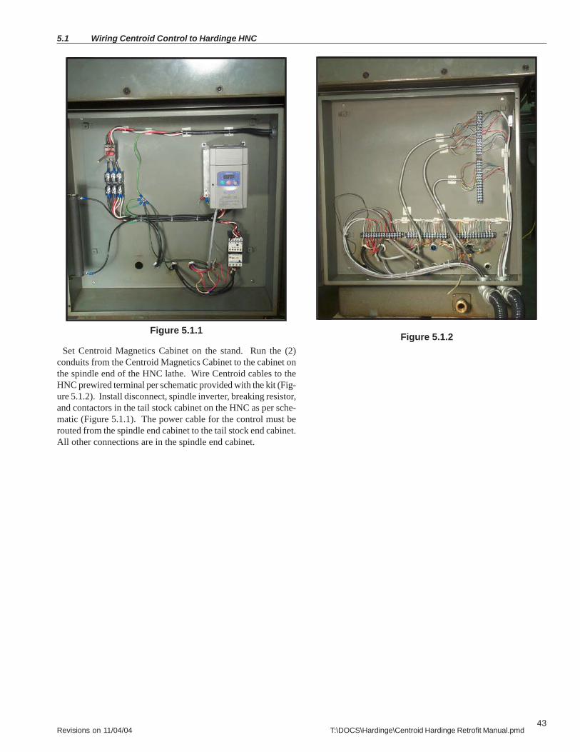
5.1 Wiring Centroid Control to Hardinge HNC
Set Centroid Magnetics Cabinet on the stand. Run the (2)conduits from the Centroid Magnetics Cabinet to the cabinet onthe spindle end of the HNC lathe. Wire Centroid cables to theHNC prewired terminal per schematic provided with the kit (Fig-ure 5.1.2). Install disconnect, spindle inverter, breaking resistor,and contactors in the tail stock cabinet on the HNC as per sche-matic (Figure 5.1.1). The power cable for the control must berouted from the spindle end cabinet to the tail stock end cabinet.All other connections are in the spindle end cabinet.
Figure 5.1.1Figure 5.1.2

44Revisions on 11/04/04 T:\DOCS\Hardinge\Centroid Hardinge Retrofit Manual.pmd
Set Centroid Magnetic Cabinet on the stand. Run the (2) con-duits from the Centroid Magnetics Cabinet to the cabinet on theback of CHNC lathe. Wire Centroid cables to the CHNC prewiredterminals per schematic provided with the kit.
Connect the encoder cables and control cable A first, then con-nect cables B, C and D.
Install the disconnect bracket and connect the power wires.
Figure 5.2.1
Wiring Centroid Control to Hardinge CHNC 5.2
45Revisions on 11/04/04 T:\DOCS\Hardinge\Centroid Hardinge Retrofit Manual.pmd
Figure 5.3.1
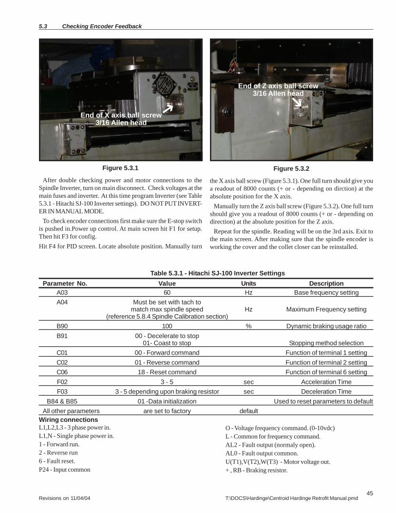
After double checking power and motor connections to theSpindle Inverter, turn on main disconnect. Check voltages at themain fuses and inverter. At this time program Inverter (see Table5.3.1 - Hitachi SJ-100 Inverter settings). DO NOT PUT INVERT-ER IN MANUAL MODE.
To check encoder connections first make sure the E-stop switchis pushed in.Power up control. At main screen hit F1 for setup.Then hit F3 for config.Hit F4 for PID screen. Locate absolute position. Manually turn
Table 5.3.1 - Hitachi SJ-100 Inverter SettingsParameter No. Value Units Description
A03 60 Hz Base frequency settingA04 Must be set with tach to
match max spindle speed Hz Maximum Frequency setting(reference 5.8.4 Spindle Calibration section)
B90 100 % Dynamic braking usage ratioB91 00 - Decelerate to stop
01- Coast to stop Stopping method selectionC01 00 - Forward command Function of terminal 1 settingC02 01 - Reverse command Function of terminal 2 settingC06 18 - Reset command Function of terminal 6 settingF02 3 - 5 sec Acceleration TimeF03 3 - 5 depending upon braking resistor sec Deceleration Time
B84 & B85 01 -Data initialization Used to reset parameters to defaultAll other parameters are set to factory default
the X axis ball screw (Figure 5.3.1). One full turn should give youa readout of 8000 counts (+ or - depending on dirction) at theabsolute position for the X axis.
Manually turn the Z axis ball screw (Figure 5.3.2). One full turnshould give you a readout of 8000 counts (+ or - depending ondirection) at the absolute position for the Z axis.
Repeat for the spindle. Reading will be on the 3rd axis. Exit tothe main screen. After making sure that the spindle encoder isworking the cover and the collet closer can be reinstalled.
5.3 Checking Encoder Feedback
Wiring connectionsL1,L2,L3 - 3 phase power in.L1,N - Single phase power in.1 - Forward run.2 - Reverse run6 - Fault reset.P24 - Input common
O - Voltage frequency command. (0-10vdc)L - Common for frequency command.AL2 - Fault output (normaly open).AL0 - Fault output common.U(T1),V(T2),W(T3) - Motor voltage out.+ , RB - Braking resistor.
End of X axis ball screw3/16 Allen head
End of Z axis ball screw3/16 Allen head
Figure 5.3.2

46Revisions on 11/04/04 T:\DOCS\Hardinge\Centroid Hardinge Retrofit Manual.pmd
Checking Limit Switches 5.4
Figure 5.4.1
5.4.1 - Limit SwitchesNext check the limit switches. To do this the table must be
manually moved to the ends of its travel. There should be amessage of Limit tripped and then Limit cleared on the screen asyou hit each limit switch. If there is no message, type F1 (Setup),F3 (Config), F2 (Machine).
Check that limits and home are set to 1 for Z-, 2 for Z+, 3 for X-and 4 for X+. This is done because the Hardinge Lathes use anormally open switch so inputs 20, 21, 22, 26 are mirrored toinputs 1 through 4.
If they all work correctly move the table manualy to the centerof its travel. If one or more do not work check for broken wires atthe White Hardinge terminal block under the axis encoder cover.These wires can be broken off of the pin but still be held in placeby the insulating tubing covering it (Figure 5.4.1).
5.4.2 - Air Switches Apply air pressure (90PSI). The light for input 18 Low Air Pres-
sure should come on when air pressure is applied. The Guardswitch also works off of air pressure. There are holes in the backrail that the guard rides on that are blocked when the guard isclosed and activates a pressure switch. This switch is connectedto input 18 (See Figure 5.4.2 for HNC and Figure 5.4.3 for CHNC).Make sure switch is working correctly. FOR CHECKOUT ONLY,TEMPORARILY BLOCK LINE TO BYPASS SWITCH.
This air switch can be replaced with a door interlock switch toeliminate the use of air for the door interlock.
Figure 5.4.2
Figure 5.4.3
Low Air
Low Air
Guard
Guard
5.4.0 - On-screen PLC Diagnostic The state of all PLC inputs and outputs can be viewed bypressing <alt-i> from the main control screen (See Figure 5.4.0).Use this screen to determine the correct operation andcofiguration of the control throughout this chapter.
Figure 5.4.0
47Revisions on 11/04/04 T:\DOCS\Hardinge\Centroid Hardinge Retrofit Manual.pmd
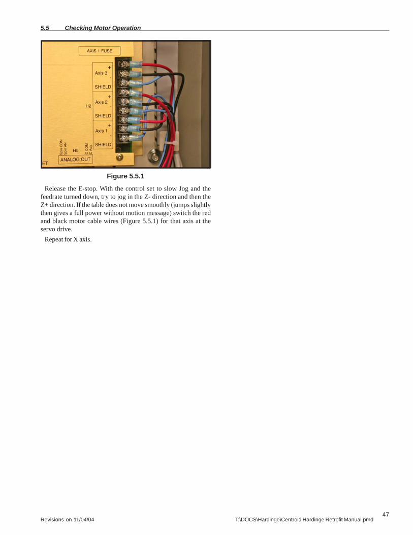
Figure 5.5.1
5.5 Checking Motor Operation
Release the E-stop. With the control set to slow Jog and thefeedrate turned down, try to jog in the Z- direction and then theZ+ direction. If the table does not move smoothly (jumps slightlythen gives a full power without motion message) switch the redand black motor cable wires (Figure 5.5.1) for that axis at theservo drive.
Repeat for X axis.

48Revisions on 11/04/04 T:\DOCS\Hardinge\Centroid Hardinge Retrofit Manual.pmd
Manually home machine. Hit F1 (Setup) ->F3 (Control) -> F2(Machine) -> F3 (Find home). Follow instructions on screen tohome the table to the X+ and then the Z+. Escape once and hit F4(Set home). Follow onscreen instuctions to set home for X and Zaxis.
Figure 5.6.1
Manual Homing of Machine 5.6
49Revisions on 11/04/04 T:\DOCS\Hardinge\Centroid Hardinge Retrofit Manual.pmd
5.7 Checking Turret Inputs
Figure 5.7.1 Figure 5.7.2
Retaining screw
Indicator
Cover markedENC2
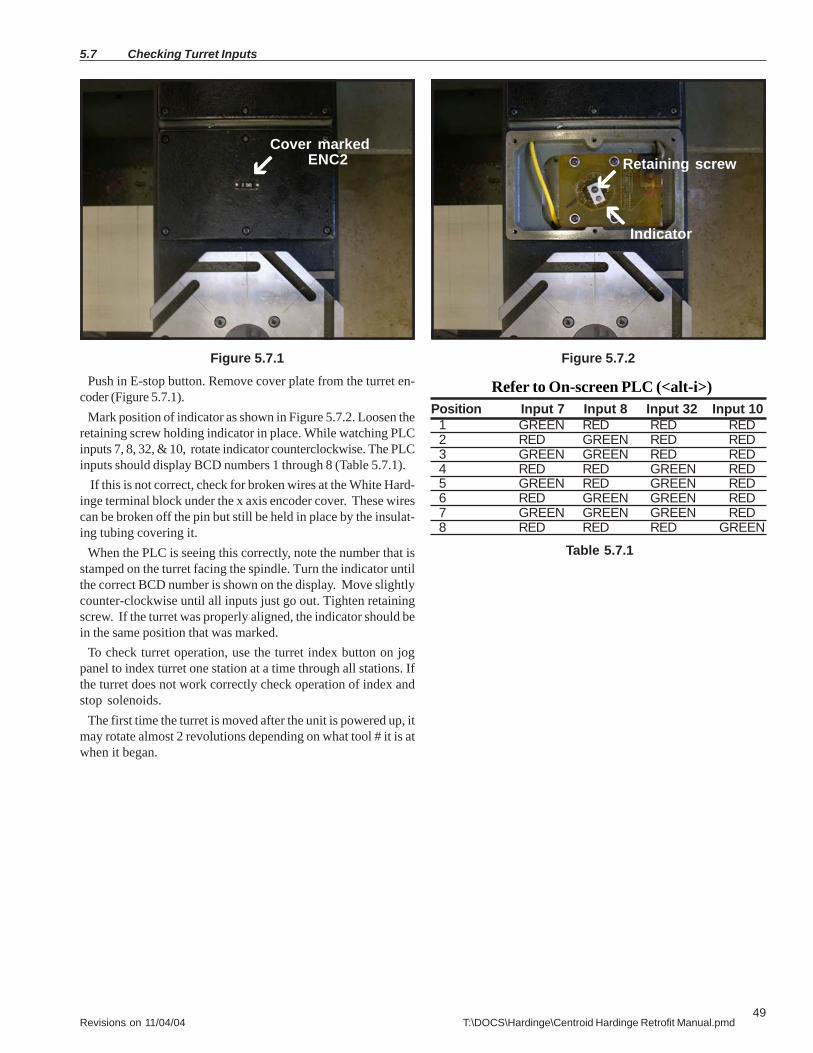
Push in E-stop button. Remove cover plate from the turret en-coder (Figure 5.7.1).
Mark position of indicator as shown in Figure 5.7.2. Loosen theretaining screw holding indicator in place. While watching PLCinputs 7, 8, 32, & 10, rotate indicator counterclockwise. The PLCinputs should display BCD numbers 1 through 8 (Table 5.7.1).
If this is not correct, check for broken wires at the White Hard-inge terminal block under the x axis encoder cover. These wirescan be broken off the pin but still be held in place by the insulat-ing tubing covering it.
When the PLC is seeing this correctly, note the number that isstamped on the turret facing the spindle. Turn the indicator untilthe correct BCD number is shown on the display. Move slightlycounter-clockwise until all inputs just go out. Tighten retainingscrew. If the turret was properly aligned, the indicator should bein the same position that was marked.
To check turret operation, use the turret index button on jogpanel to index turret one station at a time through all stations. Ifthe turret does not work correctly check operation of index andstop solenoids.
The first time the turret is moved after the unit is powered up, itmay rotate almost 2 revolutions depending on what tool # it is atwhen it began.
Position Input 7 Input 8 Input 32 Input 101 GREEN RED RED RED2 RED GREEN RED RED3 GREEN GREEN RED RED4 RED RED GREEN RED5 GREEN RED GREEN RED6 RED GREEN GREEN RED7 GREEN GREEN GREEN RED8 RED RED RED GREEN
Table 5.7.1
Refer to On-screen PLC (<alt-i>)

50Revisions on 11/04/04 T:\DOCS\Hardinge\Centroid Hardinge Retrofit Manual.pmd
Checking Turret Inputs 5.7
Solenoid
Figure 5.7.4 Figure 5.7.5
Air motorStop Solenoid
Make sure air pressure is at least 90 psi.Sequence of events for tool change1. Index solenoid turns on (OUT DRV 1) (Figure 5.7.4).2. Turret raises and air motor turns on.3. Turret rotates until PLC sees correct (or next) tool number.4. Stop solenoid turns on (OUT DRV 5) and stops turret. (Figure5.7.5)5. Index soldenoid turns off, turning off air motor and droppingturret.6. When turret drops, input 19 turns on.7. This turns off Stop solenoid and completes tool change.
Again, if this is not correct, check for broken wires at the WhiteHardinge terminal block under the X axis encoder cover. Thesewires can be broken off the pin, but still be held in place by theinsulating tubing covering it.
51Revisions on 11/04/04 T:\DOCS\Hardinge\Centroid Hardinge Retrofit Manual.pmd
5.8 Checking Operations
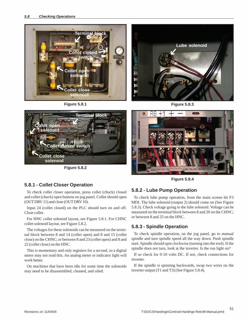
Figure 5.8.1
5.8.1 - Collet Closer OperationTo check collet closer operation, press collet (chuck) closed
and collet (chuck) open buttens on jog panel. Collet should open(OUT DRV 11) and close (OUT DRV 10).
Input 24 (collet closed) on the PLC should turn on and off.Close collet.
For HNC collet solenoid layout, see Figure 5.8.1. For CHNCcollet solenoid layout, see Figure 5.8.2.
The voltages for these solenoids can be measured on the termi-nal block between 8 and 14 (collet open) and 8 and 15 (colletclose) on the CHNC; or between 8 and 23 (collet open) and 8 and22 (collet close) on the HNC.
This is momentary and only registers for a second, so a digitalmeter may not read this. An analog meter or indicator light willwork better.
On machines that have been idle for some time the solenoidsmay need to be disassembled, cleaned, and oiled.
5.8.2 - Lube Pump OperationTo check lube pump operation, from the main screen hit F3
MDI. The lube solenoid (output 2) should come on (See Figure5.8.3). Check voltage going to the lube solenoid. Voltage can bemeasured on the terminal block between 8 and 20 on the CHNC;or between 8 and 25 on the HNC.
5.8.3 - Spindle OperationTo check spindle operation, on the jog panel, go to manual
spindle and turn spindle speed all the way down. Push spindlestart. Spindle should spin clockwise (turning into the tool). If thespindle does not turn, look at the inverter. Is the run light on?
If so check for 0-10 volts DC. If not, check connections forinverter.
If the spindle is spinning backwards, swap two wires on theinverter output (T1 and T3) (See Figure 5.8.4).
Figure 5.8.2
Figure 5.8.3
Terminal block
Collet opensolenoid
Collet closesolenoid
Collet closedswitch
Terminal block
Collet opensolenoid
Collet closesolenoid
Collet closed switch
Lube solenoid
Figure 5.8.4

52Revisions on 11/04/04 T:\DOCS\Hardinge\Centroid Hardinge Retrofit Manual.pmd
Checking Operations 5.8
5.8.4 - Spindle Calibration1. Hit F1 (Setup).2. Hit F3 (Control).3. Hit F1 (Control).4. Make sure Max spindle speed is set to 3000 RPM.5. Escape to main screen.6. On inverter, set parameter A04 to 120 Hz.7. Start spindle.8. Slowly turn spindle speed up while monitoring the spindlespeed with a tachometer. Turn speed up to 3000 RPM. Listenfor any unusual sounds from the spindle during the operation.9. Leave spindle running and read the spindle speed in Hertzon the inverter.10. Turn off spindle.11. Change parameter A04 in inverter to be 1 Hertz less than thereading from the inverter at 3000 RPM.12. Change to auto mode on jog pendant.13. Hit F3 for MDI mode.14. Type in M3S1000 and push Cycle Start.15. Turn spindle speed knob on jog panel until spindle speedon screen reads 1000 RPM.16. Check spindle speed with tachometer.17. Type S1500.18. Check spindle speed with tachometer.19. Type S2000.20. Check spindle speed with tachometer.21. Type S2500.22. Check spindle speed with tachometer.23. Type S3000.24. Check spindle speed with tachometer.25. Type S500.26. Check spindle speed with tachometer.27. Type S250.28. Check spindle speed with tachometer.29. Type S100.30. Check spindle speed with tachometer.31.Type S2000.32. Actual spindle speed should be within a couple of RPMs ofscreen reading at low RPM and can be up to 50 RPM off at highspeed.33. If needed, adjust inverter parameter A04 up or down 1 Hertzat a time to achieve this.
5.8.5 - Part Chute OperationTo check part chute operation, while in MDI mode, type in M22.Part chute should extend (OUT DRV 9). Voltage for the solenoid
can be measured on the terminal block between 8 and 13 on theCHNC (See Figure 5.8.5); and between 8 and 21 on the HNC (SeeFigure 5.8.6).
On machines that have been idle for some time the solenoidmay need to be disassembled, cleaned, and oiled. M23 shouldretract the part shute.
Figure 5.8.5
Figure 5.8.6
Terminal blockVertical slide
solenoid
Part chutesolenoid
Vertical slide solenoidTerminal block
Hydraulic pumpsolenoid
Part chutesolenoid

53Revisions on 11/04/04 T:\DOCS\Hardinge\Centroid Hardinge Retrofit Manual.pmd
5.8 Checking Operations
5.8.6 - Vertical Slide OperationTo check vertical slide operation, turn on spindle at low speed.
In MDI mode, type in M13. Vertical slide solenoid (OUT DRV 6)and Hydraulic pump solenoid (Output 30, NO) come on.Slide moves down until slide down (Input 28) is tripped (SeeFigure 5.8.7 for CHNC or Figure 5.8.8 for HNC) then vertical slidesolenoid (OUT DRV 6) turns off. When slide up (Input 27) ordwell time expires, Hydraulic pump solenoid (Output 30, NO)turns off.Voltage for vertical slide can be measured on terminal block be-tween 8 and 24 on the HNC; and between 8 and 16 on the CHNC.Hydraulic pump solenoid voltage can be measured between 8and 18 on the CHNC.
Figure 5.8.7
5.8.7 - Coolant Pump OperationTo check coolant pump operation, check to ensure that coolant
pump hoses are connected and valves are turned off. In manualmode, turn on coolant pump (output 3) (See Figure 5.8.9 for CHNCor Figure 5.8.10 for HNC). Check for correct rotation of pump. Ifpump does not turn on check that overload on coolant contactoris not tripped. Measure voltage on coolant contactor at 95nc toA1 (24vac) (See Figure 5.8.11 for CHNC or Figure 5.8.12 for HNC).
Figure 5.8.8
Slide downswitch Slide down
switch
Figure 5.8.9 Figure 5.8.10
Figure 5.8.11
Slide up switch
Figure 5.8.12

54Revisions on 11/04/04 T:\DOCS\Hardinge\Centroid Hardinge Retrofit Manual.pmd
5.8.7 - Spindle Lock Pin OperationTo check spindle lock pin operation, make sure spindle is in
auto mode. In MDI mode, type in M19. Spindle will spin at 100RPM. When spindle is at speed (input 13), spindle lock pin inturns on (RLYBRD 2, K2 OUT). When spindle locked switch isseen (input 19), spindle (output 14) turns off.
Type in M5, and lock pin will retract (RLYBRD 3, K1 OUT). Lockpin in solenoid voltage can be measured between 8 and 10 on theCHNC. Lock pin out solenoid voltage can be measured between8 and 11 on the CHNC.
Figure 5.8.13
Figure 5.8.14
Lock pin
Lock pinswitch
Lock pin in
Lock pin out
Checking Operations 5.8

55Revisions on 11/04/04 T:\DOCS\Hardinge\Centroid Hardinge Retrofit Manual.pmd
5.8.8 - Coolant contactorThe voltage for the coolant contactor is on control cable C.
This is one of the 18/5 cables. The red wire is 24vac1 and thebrown wire is 24vac2. This is turned on and off by PLC output 3.
5.8.9 - Turret solenoidsThe stop and index solenoids operate on the same +12vdc as
the limits and all of the other switches and sensors. They areturned on by PLC OUT DRV 5 (stop) and OUT DRV 1 (index).OUT DRV 5 connects the blue wire in control cable A to 12vdccommon and OUT DRV 1 connects the green wire in controlcable A to 12vdc common. These wires connect to the originalHardinge cabling.
5.8.10 - Other solenoidsAll of the other solenoids operate on 110vac. They all use the
same neutral wire. This is the white wire in control cable C. Theyare all turned on by the PLC connecting them to 110vac hot.
Collet open, OUT DRV 11, control cable B brown wireCollet close, OUT DRV 10, control cable B red wirePart chute in, OUT DRV 9, control cable B green wireLockpin out, OUT DRV 8, control cable B white wireLockpin in, OUT DRV 7, control cable B black wireVertical slide down, OUT DRV 6, control cable D white wireLube on, OUT 2, control cable D black wireHydraulic pump on, OUT 30, NO, control cable D green wire
These wires connect to the original Hardinge cabling.
5.8.11 - Limit/Home switchesThe limits are actually Hall effect sensors and turn on when
tripped. They are connected to inputs 20, 21, 22, & 26. Becausethey turn on (close) when tripped, inputs 20, 21, 22, & 26 aremirrored to inputs 1 through 4. This allows the software to seethe limits as opening when tripped on inputs 1 through 4. That iswhy on the setup screen the limits and home switches are listedas 1 through 4. The limits are connected to the PLC by controlcable A and are pulled down to 12vdc common when tripped.
Z- limit, Brown wire, input 20Z+ limit, Red wire, input 21X- limit, Orange wire, input 22X+ limit, Yellow wire, input 26
These wires connect to the original Hardinge cabling.
5.8.12 - Other Hardinge sensorsThe following are Hall effect sensors that pull down to 12vdc
common to the input they are connected to through the controlcable A.
Turret down, white wire, input 28Slide down, white/black/violet wire, input 17Spindle locked, white/red wire, input 27Slide up, white/black/blue wire, input 19
These wires connect to the original Hardinge cabling.The following are air pressure activated switches and pull up
+12vdc to the input they are connected to by control cable A.Guard closed, white/gray wire, input 15Air pressure OK, violet wire, input 18Collet closed, black wire, input 24
These wires connect to the original Hardinge cabling.
On a CHNC only, the coolant level switches are magnetic floatswitches and pull up +12vdc to the input they are connected tothrough control cable A.
Coolant low, white/black/brown wire, input 30Coolant high, white/brown/orange wire, input 14
These wires connect to the original Hardinge cabling.
The turret position is sent to the PLC as a BCD number. Thesepull up +12vdc to the input they are connected to.
1st digit (pos. A), white/black/red wire, input 72nd digit (pos. B), white/black/orange wire, input 83rd digit (pos. C), white/black/yellow wire, input 324th digit (pos. D), white/black/green wire, input 10
These wires connect to the original Hardinge cabling.
Position Input 7 Input 8 Input 32 Input 101 GREEN RED RED RED2 RED GREEN RED RED3 GREEN GREEN RED RED4 RED RED GREEN RED5 GREEN RED GREEN RED6 RED GREEN GREEN RED7 GREEN GREEN GREEN RED8 RED RED RED GREEN
5.8.13 - Inverter OperationThe common for the inverter is P24 (+24vdc). It is connected to
PLC output 15 common and output 14 common (control cable A,white/yellow wire).
Output 13 SPINDLE CW is connected to the inverter pin 1through the E-stop contactor L1 (white wire #30 to contactorthen to control cable A, white/violet wire).
Output 13 SPINDLE CCW is connected to the inverter pin 2through the E-stop contactor L2 (black wire #31 to contactorthen to control cable A, white/green wire).
Output 15, white/blue wire, Resets the inverter (pin 6) when afault is detected. Output 15 only turns on when the control seesan inverter fault signal and the E-stop signal at the same time.
0 to 10vdc from the PLC ANALOG OUT (0-10v) and ANALOGCOMMON is connected to the inverter to control the spindlespeed.
0-10vdc, white/black/gray wire, inverter pin OCommon, gray wire, inverter pin L
5.8 Trouble Shooting
Refer to On-screen PLC (<alt-i>)

56Revisions on 11/04/04 T:\DOCS\Hardinge\Centroid Hardinge Retrofit Manual.pmd
There are 2 outputs on the inverter that are connected to thePLC. They pull the input low when tripped.
Inverter fault is a switch that closes when the inverter faultsout.
At Speed is an open collector output that turns on when theprogrammed spindle speed is reached.
Fault, inverter pin AL2, white/brown/red wire, input 25At Speed, inverter pin 11, white/brown/yellow wire, input 13Common, inverter pin AL0 and CM2, white/brown wire, 12vdc
commonOn a CNC model these wires connect directly to the inverter
(except the white/brown wire). On a HNC model there is a sec-ondary cable.
5.8.14 - Control PowerThe control power is supplied by a 14/3 SJO cable. It is con-
nected to the Disconnect and Fuses installed in the Hardingecabinet. Make sure that if the incoming 3-phase has a wild (high)line that the control power cable is NOT attached to that line.
5.8.15 - EncodersThe encoders are connected to the original Hardinge cable by
butt splicing a pigtail (provided) on to the Hardinge cables. Thesecables are attached to terminal blocks in the Hardinge cabinet.The encoder cables than go to a DB9 connector for the CPU10 onthe back of the PC.
Encoder +5vdc to the DB9 connector pin 9Encoder 5v common to the DB9 connector pin 2Encoder channel A to the DB9 connector pin 7Encoder channel A\ to the DB9 connector pin 4Encoder channel B to the DB9 connector pin 8Encoder channel B\ to the DB9 connector pin 5Encoder channel Z to the DB9 connector pin 6Encoder channel Z\ to the DB9 connector pin 3Encoder shield to the DB9 connector body
5.8.16 - Motor PowerIf using the original Hardinge axis servo motors the Centroid
motor power cables are connected to the original Hardinge ca-bles. If Centroid supplied axis servo motors are used the Cen-troid motor power cables are connected to the original Hardingecables and then the other end of the Hardinge cables are buttspliced to the motors.If the original axis servo motors are reused the connections at theservo drive may need to be reversed. This is indicated by thetable moving for a short distance and then giving a positionerror. The table will also move in the same direction no matterwhich direction that it is told to move.
If the axis servo motors are replaced only the X axis motor cableconnections will have to be reversed because of the encoderbeing mounted on the ball screw facing the motor. This causesthe control to think that the motor is turning backwards from thecommanded direction.
5.8.17 - Collet open and closeThe Collet open (OUT DRV 11) and Collet close (OUT DRV 10)
solenoids are only turned on momentarily. Most digital meterswill not be able to measure the voltage to these solenoids as theydo not react quickly enough. Use an analog meter or an indicatorlight to measure the voltage to these solenoids. Listen for thesound of the solenoids firing. If the Lathe has not been used insome time the solenoids may be sticking. This can be determinedby hearing the solenoid fire but the collet does not open or close.If this is the case the solenoid valve may need to be disassem-bled cleaned and oiled. If the control does not see the colletclosed signal (INP 24) the spindle will not turn on.
5.8.18 - Part chuteThe part chute solenoid valve is turned on (OUT DRV 9, M22)
until told to retract (M23). If the Lathe has not been used in sometime the solenoids may be sticking. This can be determined byhearing the solenoid fire but the part chute does not extend orretract. If this is the case the solenoid valve may need to bedisassembled cleaned and oiled.
5.8.19 - Spindle Lockpin operationThe spindle must be in auto mode. On receiving M19 the spin-
dle turns on CW (output 13) at 100rpm. When the PLC sees the atspeed signal (input 13) from the inverter the lockpin in solenoidturns on (OUT DRV 7). When the PLC sees the spindle lockedsignal (input 19) the spindle turns off. Lockpin retracts (OUTDRV 8) when it is given a M5.
5.8.20 - Vertical Slide (cut off) operationThe spindle must be turning. When receiving M13 the vertical
slide solenoid (OUT DRV 6) and the hydraulic pump solenoid(OUT 30, NO) turn on. The slide will come down until the slidedown sensor (input 28) is tripped. Vertical slide solenoid (OUTDRV 6) turns off. When the slide up sensor (input 27) or thedwell time expires, the hydraulic pump solenoid (OUT 30, NO)turns off.
On units without slide up sensor, input 27 must be jumpered to12vac common.
5.8.21 - Lube operationThe lube solenoid (output 2) turns on whenever the control is
in “program running” mode (MDI mode or running a program).Lube pump is always on in “program running” mode. Flow is
adjusted by turning the flow adjustment knobs on the lube pump.
Checking Operations 5.8

57Revisions on 11/04/04 T:\DOCS\Hardinge\Centroid Hardinge Retrofit Manual.pmd
Chapter 6
Parts List
6.1 Supplied Parts

58Revisions on 11/04/04 T:\DOCS\Hardinge\Centroid Hardinge Retrofit Manual.pmd
Supplied Parts 6.1
Supplied Parts (All retrofits)1 - M39hp cabinet prewired1 - Cabinet stand with hardware1 - Keyboard and monitor tray with hardware1 - Jog pendant bracket with mounting hardware3 - Encoders, 2000 line for 1/4 inch shaft3 - Pigtails with attached butt splices3 - 6-32x1/4” panhead Phillips screws with lock washers1 - Spindle encoder shaft1 - Hitachi SJ00 5 HP inverter with mounting hardware (4 - 8-32x3/8” with internal lockwashers)1 - Braking resistor with mounting hardware (2 - 8-32x1/4” withinternal lockwashers)1 - Lincoln 5 HP inverter rated spindle motor with mounting hard-ware, prewired for CHNC1 - Coolant contactor 24vac coil with mounting hardware (2 - 8-32x3/8” with internal lockwashers) and snubber1 - Thermal overload protector2 - SR-50-500 strain relief (1 for spindle motor, 1 for power in)5 - 15 position terminal blocks with mounting hardware (10 6-32x1/2” php and internal tooth lockwashers)10 feet of 12/4 SJOW cable (power in)3 - 30 amp time delay fuses1 - 3 fuse, fuse block mounted on old style M-400 disconnectbracket with hardware
If new servo motors are needed2 - 17 in/lb servo motors2 - 24 tooth pulleys (for 2 to 1 ratio)1 - X axis motor mounting plate with mounting hardware1 - Z axis motor mounting plate with mounting hardware1 - X axis belt1 - SR-50-375 strain relief (HNC only)1 - 1/2 NPT plug (HNC only)4 - Butt splices 12-10 AWG (yellow)
HNC with Vari-drive spindle10 feet of 12/4 SJOW cable10 feet of 14/3 SJOW cable10 feet of 12 conductor 22 AWG cable17 - Blue ring terminals #105 - Blue butt splicesPaper template for marking spindle motor mounting holesSpindle beltBored-out pulley from vari-drive2 - SR-50-375 strain relief1 - SR-50-500 strain relief1 - 1/8 NPT plug for Vari-drive lube line
1 - Rotary disconnect and long shaft with mounting hardware1 - Disconnect handle
CHNC with DC spindle motorSpindle encoder mounting plateSpindle motor mounting alignment plate2 - 1/4-20x3/8” with locknuts1 - Rotary disconnect with short shaft12 - Blue ring terminals #104 - Blue ring terminals 1/4 inch1 - Blue butt splice2 - Red butt splices4 - 1/2-13x1-3/4” bolts10” channel gasket1 - old style M400 disconnect bracket
CHNC4Same as CHNC, but with larger spindle encoder shaft
Parts that are good to havein case they are neededSpare fusesExtra butt splices of all sizesExtra ring terminals of all sizesExtra spade terminals of all sizesExtra hardware to replace missing hardware on the Hardinge10-32 and 1/4-20 socket head cap screws are the most commonFlat and lock washers #10 & 1/4 inchExtra belts for Hardinge
Tools that are needed1. 1 1/4” conduit punch.2. A .035 Allen wrench for removal of existing feedback couplers.3. A 1.5mm Allen wrench for installing the new encoders4. Standard Allen wrench set from 0.050 to 3/8”.5. A center punch.6. A fine tip permanent marker (Sharpie ultra fine point).7. Combination wrenches from 1/4” to 7/8”.8. Number 35, 29, 19, and 11/32” drill bits (More than one in casethey break).9. 6-32, 8-32, and 10-32 taps (More than one in case they break).10. A tap handle for small taps.11. Tap Magic or equivalent.12. A 17/32 drill bit for the CHNC or a 5/16 drill bit and 3/8-16 tapwith handle for the HNC13. For the CHNC a notch must be made for spindle motor clear-ance. A Sawzall, hand grinder or some other tool to cut out thenotch is needed.
59Revisions on 11/04/04 T:\DOCS\Hardinge\Centroid Hardinge Retrofit Manual.pmd
Supplied Parts 6.2
Tools that are needed (continued)14. A step drill from 1/4” to 7/8”.15. A very good pair of crimpers.16. #2 Phillips head screwdriver (A second #2 with a long shaftmakes it easier to connect the wires to the terminal strips).17. Assorted straight screwdrivers.18. A pair of small needle nose pliers.19. Wire cutters.20. Wire strippers.21. A sharp utility knife.22. A crescent wrench or channel lock pliers that open up to at least1 1/2”.23. A good drill (cordless drill is not recommended but will work).24. A good multi meter.25. A small soldering iron and solder (for repairing pins at the Hard-inge terminal blocks).26. A work light.27. Tie wraps.28. A spray bottle of 409 cleaner.29. A Scotch Bright pad.30. A marker to mark the cables with.31. WD-40 or equivalenet.32. Rags.33. A dial indicator to check that the turns per inch are set.34. A tachometer to measure spindle speed.