CENTRIFUGE DRIER / FILTER « CENTRIFILTER »
7
CENTRIFUGE DRIER / FILTER « CENTRIFILTER » APPLICATION: Particles and water contaminants are the most usual cause of problems in process analyse. According to ASTM D4007-02 Method for Water and Sediment separation in oil , the centrifuge separation, proved to be the most effective method, was complicated and expensive to implement in sampling systems; the CENTRIFILTER solved definitely this type of consideration.
-
Upload
declan-martin -
Category
Documents
-
view
63 -
download
10
description
CENTRIFUGE DRIER / FILTER « CENTRIFILTER ». APPLICATION: Particles and water contaminants are the most usual cause of problems in process analyse. - PowerPoint PPT Presentation
Transcript of CENTRIFUGE DRIER / FILTER « CENTRIFILTER »

CENTRIFUGE DRIER / FILTER « CENTRIFILTER »
APPLICATION:
Particles and water contaminants are the most usual cause of problems in process analyse.
According to ASTM D4007-02 Method for Water and Sediment separation in oil , the centrifuge separation, proved to be the most effective method, was complicated and expensive to implement in sampling systems; the CENTRIFILTER
solved definitely this type of consideration.

CENTRIFUGAL SEPARATION FUNDAMENTALS
For filtration, the centrifugal force depends upon the radius and speed of rotation and upon the mass of the particle
For oil @SG: 0.9 dewatering, the water centrifugal force per unit volume will be 10% greatest .
Therefore water will move to occupy the annulus at the periphery of the bowl and it will displace the oil towards the centre.
The centrifugal g of CENTRIFILTER g = 2240 m/s²
= 1..12 r n²/1000 with (r = 80 mm bowl radius & n= 5000 rev/mn)
The speed of water droplet in oil @ SG:0.9 / v: 8 cSt is 1 mm/h @ g1 corresponding to 2240 mm/h in centrifilter.
Distance from rotor to periphery is 65 mm therefore residence time should be 105 sec. Considering the bowl volume of 440 cc a complete dewatering should be achieved
for maximum sample flow rate of 15 l/h.
In the AS 300 FTIR analyser cell, the flow rate is 3.6 l/h.
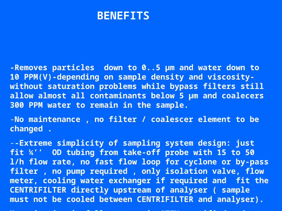
-Removes particles down to 0..5 µm and water down to 10 PPM(V)-depending on sample density and viscosity- without saturation problems while bypass filters still allow almost all contaminants below 5 µm and coalecers 300 PPM water to remain in the sample.
-No maintenance , no filter / coalescer element to be changed .
--Extreme simplicity of sampling system design: just fit ¼’’ OD tubing from take-off probe with 15 to 50 l/h flow rate, no fast flow loop for cyclone or by-pass filter , no pump required , only isolation valve, flow meter, cooling water exchanger if required and fit the CENTRIFILTER directly upstream of analyser ( sample must not be cooled between CENTRIFILTER and analyser).
Motorisation is fully pneumatic ATEX certified and separated water is to be drained .
BENEFITS

THE MAIN PARTS
PNEUMATIC MOTOR
SAMPLE INLET
SAMPLE INJECT
CLARIFIED SAMPLE OUTLET
BOWLGRAVITY DISC
WATER RIVULET CHANNEL WATER OUTWARDS EJECTORS
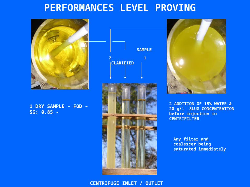
PERFORMANCES LEVEL PROVING
1 DRY SAMPLE - FOD – SG: 0.85 -
2 ADDITION OF 15% WATER & 20 g/l SLUG CONCENTRATION before injection in CENTRIFILTER
2 1 CLARIFIED
SAMPLE
Any filter and coalescer being saturated immediately
CENTRIFUGE INLET / OUTLET

TECHNICAL SPECIFICATIONS
-Percentage of particles removed during evaluation test carried on FOD @ 15 l/h sample flow rate :
96.7 % >0.5 µm
99.8 % >15 µm
Water removal content at 25°C < 20 PPM
-Sample inlet/oulet pressure : min. 0.5 bar g, max. 7 bar g
-Water separated outlet pressure: max. 2 bar g
-Sample temperature: 120 °C max.
-Wetted parts : St. St 316L and PTFE
- Typical applications : crude-oil / diesel-oil / gasolines / kerosene / naphtha / lube-oil

MAINTENANCE SUPERIORITY PROVING
WATER RIVULET CHANNEL
100 % CLEAN
ALL SLUGS ACCUMULATED IN THE BOWL
FURTHER TO 24 H RUN WITH 15% WATER & 20 g/l SLUG CONCENTRATION IN SAMPLE (SATURATION LEVEL)
No element to be changed