Centrifuga Beckman spinchron
56
SDLX-IM-8 Spinchron ™ DLX Benchtop Centrifuge Instruction Manual ENTER PULSE STOP START
-
Upload
alain-martinez -
Category
Documents
-
view
252 -
download
5
description
manual de referencia
Transcript of Centrifuga Beckman spinchron

SDLX-IM-8
Spinchron™ DLX Benchtop CentrifugeInstruction Manual
IMBALANCE ENTER
PULSE
ACCEL
DECEL
RPM RCF ROTOR TIME
STOP START
FAST STOP
OPEN DOOR
SPEED TIME
ACC/DEC
™
® MADE IN U.S.A.
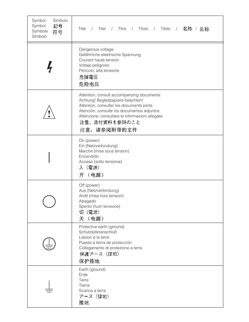
SymbolSymbolSymboleSímbolo
Title / Titel / Titre / Titulo / Titolo /
Dangerous voltageGefährliche elektrische SpannungCourant haute tensionVoltaje peligrosoPericolo: alta tensione
Attention, consult accompanying documentsAchtung! Begleitpapiere beachten!Attention, consulter les documents jointsAtención, consulte los documentos adjuntosAttenzione: consultare le informazioni allegate
On (power)Ein (Netzverbindung)Marche (mise sous tension)EncendidoAcceso (sotto tensione)
Off (power)Aus (Netzverbindung)Arrêt (mise hors tension)ApagadoSpento (fuori tensione)
Protective earth (ground)SchutzleiteranschlußLiaison à la terrePuesta a tierra de protecciónCollegamento di protezione a terra
Earth (ground)ErdeTerreTierraScarica a terra
!
/
Simbolo
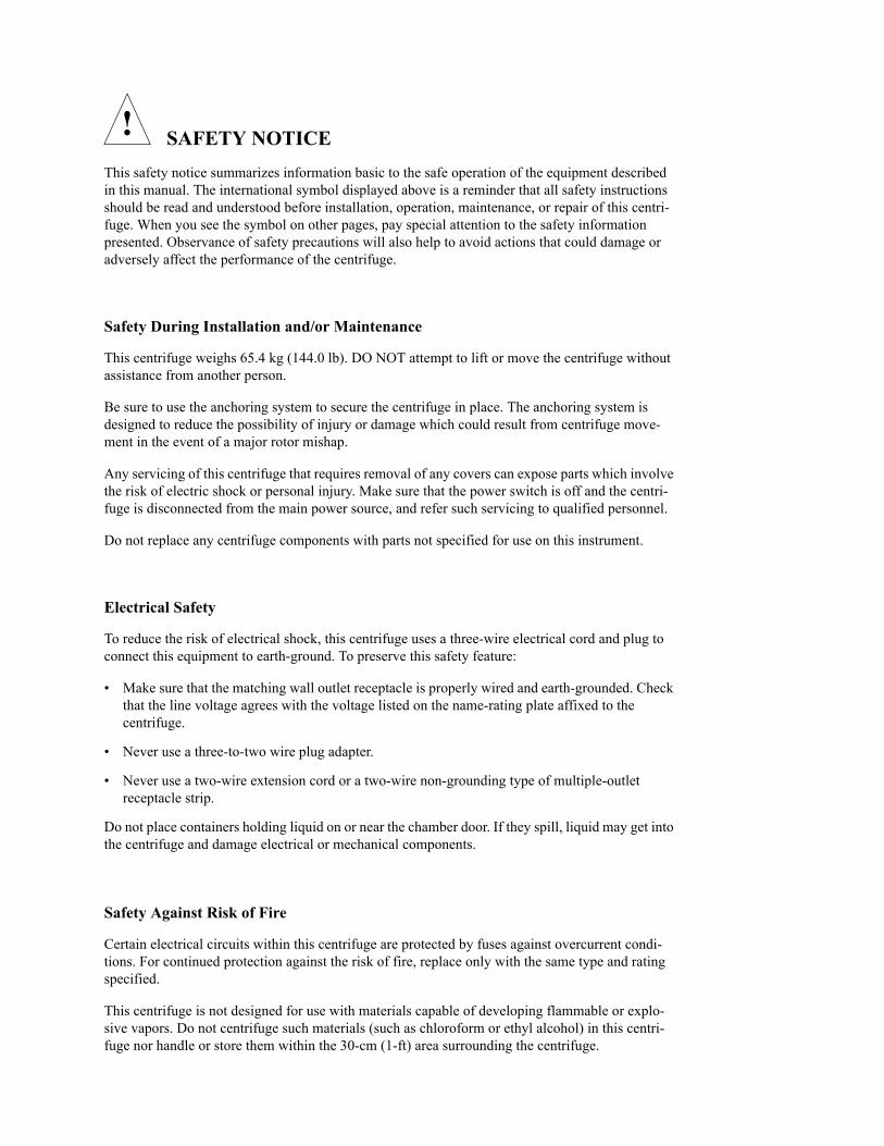
SAFETY NOTICE
This safety notice summarizes information basic to the safe operation of the equipment described in this manual. The international symbol displayed above is a reminder that all safety instructions should be read and understood before installation, operation, maintenance, or repair of this centri-fuge. When you see the symbol on other pages, pay special attention to the safety information presented. Observance of safety precautions will also help to avoid actions that could damage or adversely affect the performance of the centrifuge.
Safety During Installation and/or Maintenance
This centrifuge weighs 65.4 kg (144.0 lb). DO NOT attempt to lift or move the centrifuge without assistance from another person.
Be sure to use the anchoring system to secure the centrifuge in place. The anchoring system is designed to reduce the possibility of injury or damage which could result from centrifuge move-ment in the event of a major rotor mishap.
Any servicing of this centrifuge that requires removal of any covers can expose parts which involve the risk of electric shock or personal injury. Make sure that the power switch is off and the centri-fuge is disconnected from the main power source, and refer such servicing to qualified personnel.
Do not replace any centrifuge components with parts not specified for use on this instrument.
Electrical Safety
To reduce the risk of electrical shock, this centrifuge uses a three-wire electrical cord and plug to connect this equipment to earth-ground. To preserve this safety feature:
• Make sure that the matching wall outlet receptacle is properly wired and earth-grounded. Check that the line voltage agrees with the voltage listed on the name-rating plate affixed to the centrifuge.
• Never use a three-to-two wire plug adapter.
• Never use a two-wire extension cord or a two-wire non-grounding type of multiple-outlet receptacle strip.
Do not place containers holding liquid on or near the chamber door. If they spill, liquid may get into the centrifuge and damage electrical or mechanical components.
Safety Against Risk of Fire
Certain electrical circuits within this centrifuge are protected by fuses against overcurrent condi-tions. For continued protection against the risk of fire, replace only with the same type and rating specified.
This centrifuge is not designed for use with materials capable of developing flammable or explo-sive vapors. Do not centrifuge such materials (such as chloroform or ethyl alcohol) in this centri-fuge nor handle or store them within the 30-cm (1-ft) area surrounding the centrifuge.
!
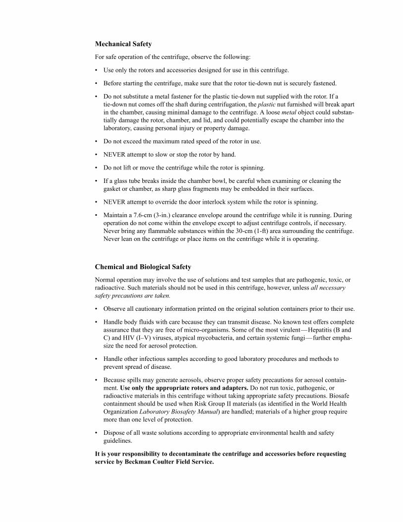
Mechanical Safety
For safe operation of the centrifuge, observe the following:
• Use only the rotors and accessories designed for use in this centrifuge.
• Before starting the centrifuge, make sure that the rotor tie-down nut is securely fastened.
• Do not substitute a metal fastener for the plastic tie-down nut supplied with the rotor. If a tie-down nut comes off the shaft during centrifugation, the plastic nut furnished will break apart in the chamber, causing minimal damage to the centrifuge. A loose metal object could substan-tially damage the rotor, chamber, and lid, and could potentially escape the chamber into the laboratory, causing personal injury or property damage.
• Do not exceed the maximum rated speed of the rotor in use.
• NEVER attempt to slow or stop the rotor by hand.
• Do not lift or move the centrifuge while the rotor is spinning.
• If a glass tube breaks inside the chamber bowl, be careful when examining or cleaning the gasket or chamber, as sharp glass fragments may be embedded in their surfaces.
• NEVER attempt to override the door interlock system while the rotor is spinning.
• Maintain a 7.6-cm (3-in.) clearance envelope around the centrifuge while it is running. During operation do not come within the envelope except to adjust centrifuge controls, if necessary. Never bring any flammable substances within the 30-cm (1-ft) area surrounding the centrifuge. Never lean on the centrifuge or place items on the centrifuge while it is operating.
Chemical and Biological Safety
Normal operation may involve the use of solutions and test samples that are pathogenic, toxic, or radioactive. Such materials should not be used in this centrifuge, however, unless all necessary safety precautions are taken.
• Observe all cautionary information printed on the original solution containers prior to their use.
• Handle body fluids with care because they can transmit disease. No known test offers complete assurance that they are free of micro-organisms. Some of the most virulent—Hepatitis (B and C) and HIV (I–V) viruses, atypical mycobacteria, and certain systemic fungi—further empha-size the need for aerosol protection.
• Handle other infectious samples according to good laboratory procedures and methods to prevent spread of disease.
• Because spills may generate aerosols, observe proper safety precautions for aerosol contain-ment. Use only the appropriate rotors and adapters. Do not run toxic, pathogenic, or radioactive materials in this centrifuge without taking appropriate safety precautions. Biosafe containment should be used when Risk Group II materials (as identified in the World Health Organization Laboratory Biosafety Manual) are handled; materials of a higher group require more than one level of protection.
• Dispose of all waste solutions according to appropriate environmental health and safety guidelines.
It is your responsibility to decontaminate the centrifuge and accessories before requesting service by Beckman Coulter Field Service.
SDLX-IM-8December 2007
Spinchron™ DLX Benchtop CentrifugeInstruction Manual
IMBALANCEENTER
PULSE
ACCEL
DECEL
RPM RCF ROTORTIME
STOP START
FASTSTOP
OPENDOOR
SPEED
TIME
ACC/DEC
™
®MADE IN U.S.A.
© 2007–2009 Beckman Coulter, Inc.


Contents
Page
INTRODUCTION
Certification . . . . . . . . . . . . . . . . . . . . . . . . . . . . . . . . . . . . . . . . . . . . viiScope of Manual. . . . . . . . . . . . . . . . . . . . . . . . . . . . . . . . . . . . . . . . . viiConventions . . . . . . . . . . . . . . . . . . . . . . . . . . . . . . . . . . . . . . . . . . . . . viiiCFC-Free Centrifugation. . . . . . . . . . . . . . . . . . . . . . . . . . . . . . . . . . . . ixRadio Interference . . . . . . . . . . . . . . . . . . . . . . . . . . . . . . . . . . . . . . . . . xRecycling Label . . . . . . . . . . . . . . . . . . . . . . . . . . . . . . . . . . . . . . . . . . . . x
SECTION 1: DESCRIPTION
Centrifuge Function, Specifications, and Safety Features . . . . . . . . . . 1-1Centrifuge Function . . . . . . . . . . . . . . . . . . . . . . . . . . . . . . . . . . . . 1-1Specifications. . . . . . . . . . . . . . . . . . . . . . . . . . . . . . . . . . . . . . . . . 1-2Safety Features. . . . . . . . . . . . . . . . . . . . . . . . . . . . . . . . . . . . . . . . 1-2
Centrifuge Chassis . . . . . . . . . . . . . . . . . . . . . . . . . . . . . . . . . . . . . . . . 1-3Housing . . . . . . . . . . . . . . . . . . . . . . . . . . . . . . . . . . . . . . . . . . . . . 1-3Door . . . . . . . . . . . . . . . . . . . . . . . . . . . . . . . . . . . . . . . . . . . . . . . . 1-3Rotor Chamber. . . . . . . . . . . . . . . . . . . . . . . . . . . . . . . . . . . . . . . . 1-4Drive . . . . . . . . . . . . . . . . . . . . . . . . . . . . . . . . . . . . . . . . . . . . . . . 1-4
Control Panel . . . . . . . . . . . . . . . . . . . . . . . . . . . . . . . . . . . . . . . . . . . . 1-5System Keys . . . . . . . . . . . . . . . . . . . . . . . . . . . . . . . . . . . . . . . . . 1-5Parameter Keys . . . . . . . . . . . . . . . . . . . . . . . . . . . . . . . . . . . . . . . 1-6Digital Displays . . . . . . . . . . . . . . . . . . . . . . . . . . . . . . . . . . . . . . . 1-7
Available Rotors. . . . . . . . . . . . . . . . . . . . . . . . . . . . . . . . . . . . . . . . . . 1-9
SECTION 2: INSTALLATION REQUIREMENTS
Installation Requirements. . . . . . . . . . . . . . . . . . . . . . . . . . . . . . . . . . . 2-1Space and Location Requirements. . . . . . . . . . . . . . . . . . . . . . . . . 2-2Electrical Requirements. . . . . . . . . . . . . . . . . . . . . . . . . . . . . . . . . 2-3Test Run. . . . . . . . . . . . . . . . . . . . . . . . . . . . . . . . . . . . . . . . . . . . . 2-4Name Rating Plate . . . . . . . . . . . . . . . . . . . . . . . . . . . . . . . . . . . . . 2-4
iii
iv
Contents
Page
SECTION 3: OPERATION
Run Preparation . . . . . . . . . . . . . . . . . . . . . . . . . . . . . . . . . . . . . . . . . . 3-2Setting Run Parameters . . . . . . . . . . . . . . . . . . . . . . . . . . . . . . . . . . . . 3-3
Selecting a Rotor . . . . . . . . . . . . . . . . . . . . . . . . . . . . . . . . . . . . . . 3-4Setting Run Speed . . . . . . . . . . . . . . . . . . . . . . . . . . . . . . . . . . . . . 3-4Setting Run Time. . . . . . . . . . . . . . . . . . . . . . . . . . . . . . . . . . . . . . 3-5Setting Acceleration and Deceleration Rates . . . . . . . . . . . . . . . . 3-6
Starting a Run. . . . . . . . . . . . . . . . . . . . . . . . . . . . . . . . . . . . . . . . . . . . 3-7Changing Parameters During a Run. . . . . . . . . . . . . . . . . . . . . . . . . . . 3-8Stopping a Run . . . . . . . . . . . . . . . . . . . . . . . . . . . . . . . . . . . . . . . . . . . 3-9Unloading . . . . . . . . . . . . . . . . . . . . . . . . . . . . . . . . . . . . . . . . . . . . . . 3-10Summary of Run Procedures . . . . . . . . . . . . . . . . . . . . . . . . . . . . . . . 3-11
SECTION 4: TROUBLESHOOTING
User Messages . . . . . . . . . . . . . . . . . . . . . . . . . . . . . . . . . . . . . . . . . . . 4-1Other Possible Problems . . . . . . . . . . . . . . . . . . . . . . . . . . . . . . . . . . . 4-3Accessing the Rotor in Case of Power Failure. . . . . . . . . . . . . . . . . . . 4-4
SECTION 5: CARE AND MAINTENANCE
General Maintenance . . . . . . . . . . . . . . . . . . . . . . . . . . . . . . . . . . . . . . 5-1Cleaning . . . . . . . . . . . . . . . . . . . . . . . . . . . . . . . . . . . . . . . . . . . . . . . . 5-2Decontamination . . . . . . . . . . . . . . . . . . . . . . . . . . . . . . . . . . . . . . . . . 5-3Sterilization and Disinfection. . . . . . . . . . . . . . . . . . . . . . . . . . . . . . . . 5-3Tube Breakage . . . . . . . . . . . . . . . . . . . . . . . . . . . . . . . . . . . . . . . . . . . 5-3Storage and Transport . . . . . . . . . . . . . . . . . . . . . . . . . . . . . . . . . . . . . 5-4
Storage . . . . . . . . . . . . . . . . . . . . . . . . . . . . . . . . . . . . . . . . . . . . . . 5-4Returning a Centrifuge . . . . . . . . . . . . . . . . . . . . . . . . . . . . . . . . . 5-4
Supply List . . . . . . . . . . . . . . . . . . . . . . . . . . . . . . . . . . . . . . . . . . . . . . 5-5Replacement Parts . . . . . . . . . . . . . . . . . . . . . . . . . . . . . . . . . . . . . 5-5Supplies . . . . . . . . . . . . . . . . . . . . . . . . . . . . . . . . . . . . . . . . . . . . . 5-5
Warranty
v
Contents
Page
Figure 1-1. Interior View of the Spinchron DLX Centrifuge RotorChamber . . . . . . . . . . . . . . . . . . . . . . . . . . . . . . . . . . . . . . . . . . . . . . . . 1-4
Figure 2-1. Dimensions of the Spinchron DLX Centrifuge . . . . . . . . . . . . . . . . . . 2-2
Illustrations
Page
Table 3-1. Acceleration and Deceleration Rates (in Minutes:Seconds)to and from Maximum Speed. . . . . . . . . . . . . . . . . . . . . . . . . . . . . . . . 3-6
Table 4-1. Error Message Chart. . . . . . . . . . . . . . . . . . . . . . . . . . . . . . . . . . . . . . . 4-2
Table 4-2. Troubleshooting Chart . . . . . . . . . . . . . . . . . . . . . . . . . . . . . . . . . . . . . 4-3
Tables

Introduction
CERTIFICATIONTo ensure full system quality, Beckman Coulter Spinchron™ DLX centrifuges are manufactured in a registered ISO 9001 or 13485 facility. They have been designed and tested to be compliant (when used with Beckman Coulter rotors) with the laboratory equipment requirements of applicable regulatory agencies. Declarations of conformity and certificates of compliance are available at www.beckmancoulter.com.
International symbols that may be displayed on the centrifuge are illustrated and described on the inside front cover of this manual.
SCOPE OF MANUALThis manual is designed to familiarize you with the Beckman Coulter Spinchron DLX centrifuge, its functions, specifications, operation, and routine operator care and maintenance. We recommend that you read this entire manual, especially the SAFETY NOTICE and all safety-related information, before operating the centrifuge or performing instrument maintenance.
➠ NOTEA magnetized document holder (964987) is available, which can be attached to either side of the centrifuge for convenient storage of this manual, as well as applicable rotor manuals. The rotor tie-down torquing bar (356036) and emergency latch release hex wrench (929317) can also be kept in the document holder for easy access.
vii

viii
Introduction
• Section 1 contains system specifications and a brief physical and functional description of the centrifuge, including the operating controls and indicators.
• Section 2 provides instructions for installing and connecting the centrifuge.
• Section 3 contains centrifuge operating procedures. For experi-enced users, a summary of operating procedures is provided at the end of the section.
• Section 4 lists possible error messages and/or malfunctions, together with probable causes and required corrective actions.
• Section 5 contains procedures for routine operator care and main-tenance, as well as a brief list of supplies and replacement parts.
• A Program Library chart is provided as an appendix at the back of this manual. You can use this chart to record the parameters of a run for later duplication of the run conditions.
If the centrifuge is used in a manner other than specified in this manual, the safety and performance of this equipment could be impaired. Further, the use of any equipment other than that recom-mended by Beckman Coulter has not been evaluated for safety. Use of any equipment not specifically recommended in this manual and/or the appropriate rotor manual is the sole responsibility of the user.
CONVENTIONSCertain symbols are used in this manual to call out safety-related and other important information. These are reproduced and described below and on the inside of the front cover.
NOTES, CAUTIONS, AND WARNINGS
➠ NOTEUsed to call attention to important information that should be followed during installation, use, or servicing of this equipment.
Introduction
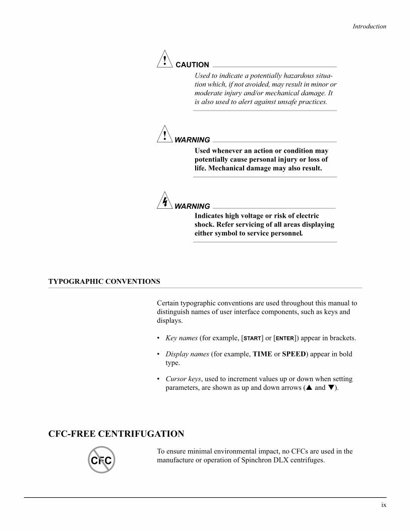
! CAUTIONUsed to indicate a potentially hazardous situa-tion which, if not avoided, may result in minor or moderate injury and/or mechanical damage. It is also used to alert against unsafe practices.
WARNING!Used whenever an action or condition may potentially cause personal injury or loss of life. Mechanical damage may also result.
WARNINGIndicates high voltage or risk of electric shock. Refer servicing of all areas displaying either symbol to service personnel.
TYPOGRAPHIC CONVENTIONS
Certain typographic conventions are used throughout this manual to distinguish names of user interface components, such as keys and displays.
• Key names (for example, [START] or [ENTER]) appear in brackets.
• Display names (for example, TIME or SPEED) appear in bold type.
• Cursor keys, used to increment values up or down when setting parameters, are shown as up and down arrows (▲ and ▼).
CFC-FREE CENTRIFUGATION
To ensure minimal environmental impact, no CFCs are used in the manufacture or operation of Spinchron DLX centrifuges.CFC
ix
x
Introduction
RADIO INTERFERENCE
This equipment has been tested and found to comply with the limits for a Class A digital device, pursuant to Part 15 of FCC Rules. These limits are designed to provide reasonable protection against harmful interference when the equipment is operated in a commercial environ-ment. This equipment generates, uses, and can radiate radio frequency energy and, if not installed and used in accordance with this instruction manual, may cause interference to radio communica-tions. Operation of this equipment in a residential area is likely to cause interference, in which case the user will be required to correct the interference at his own expense.
CANADIAN REGULATIONS
This equipment does not exceed the Class A limits for radio noise emissions from digital apparatus as set out in the radio interference regulations of the Canadian Department of Communications.
Le présent appareil numérique n’émet pas de bruits radioélectriques dépassant les limites applicables aux appareils numériques de Classe A prescrites dans le reglement sur le brouillage radioelectrique édicté par le Ministère des Communications du Canada.
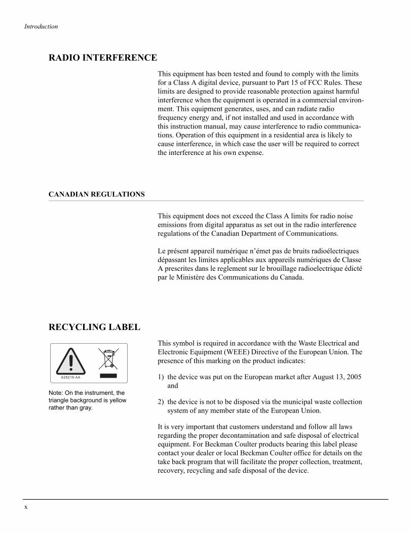
RECYCLING LABEL
This symbol is required in accordance with the Waste Electrical and Electronic Equipment (WEEE) Directive of the European Union. The presence of this marking on the product indicates:
1) the device was put on the European market after August 13, 2005 and
2) the device is not to be disposed via the municipal waste collection system of any member state of the European Union.
It is very important that customers understand and follow all laws regarding the proper decontamination and safe disposal of electrical equipment. For Beckman Coulter products bearing this label please contact your dealer or local Beckman Coulter office for details on the take back program that will facilitate the proper collection, treatment, recovery, recycling and safe disposal of the device.
A28219-AA
Note: On the instrument, the triangle background is yellow rather than gray.
1Description
CENTRIFUGE FUNCTION, SPECIFICATIONS, AND SAFETY FEATURES
CENTRIFUGE FUNCTION
The Beckman Coulter Spinchron DLX is a nonrefrigerated compact benchtop centrifuge that generates centrifugal forces required for a wide variety of applications. Together with the Beckman Coulter rotors designed for use in this centrifuge, the centrifuge applications include:
• Routine processing such as sample preparations, pelleting, extrac-tions, purifications, concentrations, phase separations, receptor binding, and column centrifugations.
• Processing large numbers of small-volume samples in multiwell plates for concentrating tissue-culture cells, cloning and replicate studies, in-vitro cytotoxicity studies, receptor binding, and genetic engineering experimentation.
• Rapid sedimentation of protein precipitates, large particles, and cell debris.
• Binding studies and separation of whole blood.
• Cell isolation.
The centrifuge is microprocessor-controlled, providing interactive operation. The centrifuge design features a brushless induction drive system, program memory that can repeat the previously used run parameters, and a choice of acceleration and deceleration rates. User messages alert the operator to conditions that may need attention.
1-1

1-2
Description
SPECIFICATIONS
Only values with tolerances or limits are guaranteed data. Values without tolerances are informative data, without guarantee.
SpeedSetting range . . . . . . . . . . . . . 0 to 3750 rpm (in 100-rpm increments)
or equivalent RCFTime
Setting range . . . . . . . . . . . . . . . . . . 1 min to 9 hr 59 min (timed run),or continuous,
or PULSEDisplay (timed run) . . . . . . . . . . . . . . . . . . . . . . . . run time remainingDisplay (continuous run) . . . . . . . . . . . . . . ∞ symbol and elapsed time
Acceleration . . . . . . . . . . . . . . . . . . . . . . . . . . . . nine acceleration profilesDeceleration . . . . . . . . . . . . . . . . . . . . . . . . . . . . nine deceleration profilesDimensions
Width . . . . . . . . . . . . . . . . . . . . . . . . . . . . . . . . . . . . 54.6 cm (21.5 in.)Depth, overall. . . . . . . . . . . . . . . . . . . . . . . . . . . . . . 66.0 cm (26.0 in.)Depth at base . . . . . . . . . . . . . . . . . . . . . . . . . . . . . . 58.4 cm (23.0 in.)Height, door closed . . . . . . . . . . . . . . . . . . . . . . . . . 40.6 cm (16.0 in.)Height, door open. . . . . . . . . . . . . . . . . . . . . . . . . . . 96.8 cm (38.1 in.)
Weight . . . . . . . . . . . . . . . . . . . . . . . . . . . . . . . . . . . . . . . 65.4 kg (144.0 lb)Surface finish
Instrument housing. . . . . . . . . . . . . . . . . . . . . . . . . . . . . urethane paintControl panel overlay. . . . . . . . . . . . . . . . . . . . . coated polycarbonate
Electrical supply . . . . . . . . . . . . . . . . . . . . . . . . . . . . . . . . . . . . . . . . Class IClearances required (sides and rear) . . . . . . . . . . . . . . . . . . 7.6 cm (3.0 in.)Maximum heat dissipation into room
under steady-state conditions . . . . . . . . . . . . . . . 0.9 kW (3701 Btu/hr)Ambient temperature range . . . . . . . . . . . . . . . . . . . . . . . . . . . . 10 to 35°CHumidity limitation . . . . . . . . . . . . . . . . . . . . . . . . . <95% (noncondensing)Noise level 1 m (3.3 ft) in front of centrifuge . . . . . . . . . . . . . . . . . ≤62 dBaInstallation (overvoltage) category . . . . . . . . . . . . . . . . . . . . . . . . . . . . . . IIPollution degree. . . . . . . . . . . . . . . . . . . . . . . . . . . . . . . . . . . . . . . . . . . . . 2*
_______________* Normally only nonconductive pollution occurs; occasionally, however, a temporary
conductivity caused by condensation must be expected.
SAFETY FEATURES
The Spinchron DLX centrifuge has been designed and tested to operate safely indoors at altitudes up to 2 000 m (6 562 ft). Safety features include the following:
• The door has an electromechanical door-locking mechanism and a secondary (manual) lock to prevent operator contact with spinning

Description
rotors. When the door is closed it locks automatically. It can be unlocked only by pressing the [OPEN DOOR] key, and opened only when the power is on, the rotor is at rest, and the manual lock is in the unlocked position. Two independent monitoring systems prevent the door from opening if the rotor is spinning.
• A steel barrier ring surrounds the aluminum rotor chamber to provide full operator protection.
• An imbalance detector monitors the rotor during the run, causing automatic shutdown if rotor loads are severely out of balance. At low speeds, an incorrectly loaded rotor can cause imbalance. Rotor instability can also occur if the centrifuge is moved while running, or if it is not resting on a level surface.
• An anchoring system is provided to secure the centrifuge in place. The anchoring system is designed to minimize the possibility of injury or damage that could result from centrifuge movement in the event of a major rotor mishap.
CENTRIFUGE CHASSIS
HOUSING
The centrifuge housing is made of sheet steel over a steel chassis and is finished with urethane paint. The control panel overlay is made of coated polycarbonate. Polyvinyl chloride lines the interior walls of the centrifuge housing for sound and temperature insulation.
DOOR
The structural steel door has two filtered air-intake ports for rotor cooling. An electromechanical door lock system, together with a manual lock, prevents run initiation unless the door is closed and latched. When a run is in progress, the door locks automatically and can be opened only when the power is on, the rotor is virtually stopped (spinning less than 40 rpm), and the lock is in the unlocked position. (A light-emitting diode [LED] on the [OPEN DOOR] key lights up when the door can be opened.) In the event of a power failure, the door lock can be manually tripped for sample recovery (see Section 4, TROUBLESHOOTING).
1-3

1-4
Description
ROTOR CHAMBER
The aluminum rotor chamber (Figure 1-1) is coated with a chemical-resistant epoxy finish. The drive shaft (1) and neoprene rubber boot (2) surrounding the drive shaft are visible in the chamber bottom. A neoprene gasket (3) around the chamber top assures sealing. (Centrifuge gaskets have not been designed as bioseals for aerosol containment.)
During centrifugation, the rotor movement draws air through the filtered air-intake ports in the door into the chamber bowl, where it circulates around the rotor. Holes in the side of the bowl (4) allow air to flow out to the exhaust ports beneath the centrifuge. This air flow provides cooling for the rotor.
Figure 1-1. Interior View of the Spinchron DLX Centrifuge Rotor Chamber
DRIVE
The asynchronous three-phase direct-drive motor is brushless for clean, quiet operation. A tie-down nut is used to attach the rotor to the drive shaft. The resilient suspension ensures that loads will not be disturbed by vibration, and prevents damage to the drive shaft if an imbalance occurs during centrifugation. Maximum braking may be
3
2
4
1

Description
selected to reduce deceleration time, allowing fast processing of samples; alternately, delicate gradients may be preserved using slower deceleration.
CONTROL PANELMounted at an angle on the centrifuge front for easy visibility and access, the control panel comprises touch keys—system keys and parameter keys—and digital displays. An IMBALANCE LED at the lower left of the panel flashes if the rotor load is severely out of balance.
The power switch, a two-position rocker switch (off—O; on—I), is mounted on the right side of the centrifuge.
SYSTEM KEYS
Centrifuge operation is controlled through the system keys. Each system key (except [PULSE]) has an LED in the upper left corner that lights up to indicate that the key can be activated.
[OPEN DOOR] Unlatches the electromechanical lock and allows the door to be opened (when the manual lock is in the unlocked position); the centrifuge will accept this command only when the rotor is completely stopped and the LED is lit.
[FAST STOP] Causes the centrifuge to decelerate to a complete stop at the maximum rate; deceleration cannot be interrupted—the centrifuge can only be restarted after the rotor stops and the door is opened and closed.
SPEED TIME ACC/DEC
IMBALANCE
ENTER
PULSE
ACCEL
DECEL
RPM RCF ROTOR TIME
STOP STARTFASTSTOP
OPENDOOR
1-5
1-6
Description
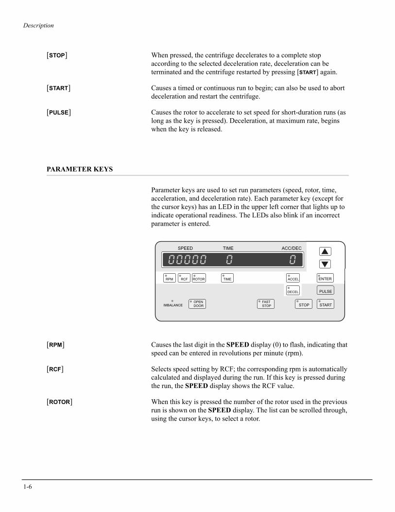
[STOP] When pressed, the centrifuge decelerates to a complete stop according to the selected deceleration rate, deceleration can be terminated and the centrifuge restarted by pressing [START] again.
[START] Causes a timed or continuous run to begin; can also be used to abort deceleration and restart the centrifuge.
[PULSE] Causes the rotor to accelerate to set speed for short-duration runs (as long as the key is pressed). Deceleration, at maximum rate, begins when the key is released.
PARAMETER KEYS
Parameter keys are used to set run parameters (speed, rotor, time, acceleration, and deceleration rate). Each parameter key (except for the cursor keys) has an LED in the upper left corner that lights up to indicate operational readiness. The LEDs also blink if an incorrect parameter is entered.
[RPM] Causes the last digit in the SPEED display (0) to flash, indicating that speed can be entered in revolutions per minute (rpm).
[RCF] Selects speed setting by RCF; the corresponding rpm is automatically calculated and displayed during the run. If this key is pressed during the run, the SPEED display shows the RCF value.
[ROTOR] When this key is pressed the number of the rotor used in the previous run is shown on the SPEED display. The list can be scrolled through, using the cursor keys, to select a rotor.
SPEED TIME ACC/DEC
IMBALANCE
ENTER
PULSE
ACCEL
DECEL
RPM RCF ROTOR TIME
STOP STARTFASTSTOP
OPENDOOR
Description
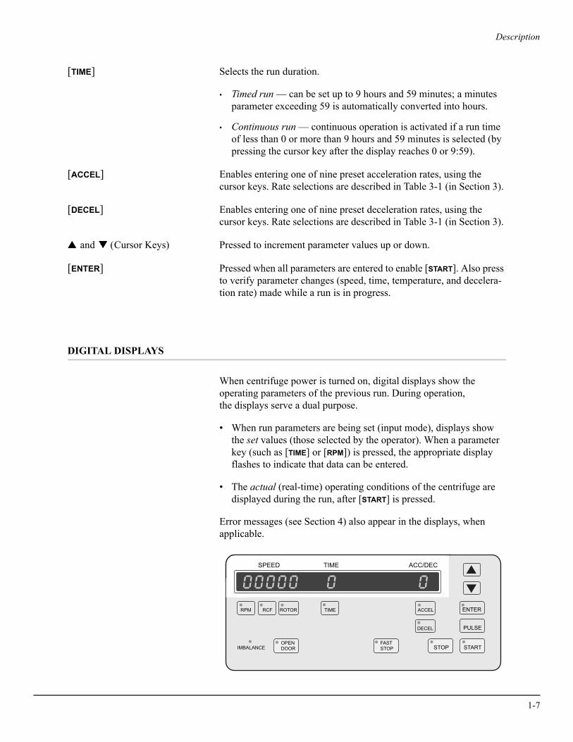
[TIME] Selects the run duration.
• Timed run — can be set up to 9 hours and 59 minutes; a minutes parameter exceeding 59 is automatically converted into hours.
• Continuous run — continuous operation is activated if a run time of less than 0 or more than 9 hours and 59 minutes is selected (by pressing the cursor key after the display reaches 0 or 9:59).
[ACCEL] Enables entering one of nine preset acceleration rates, using the cursor keys. Rate selections are described in Table 3-1 (in Section 3).
[DECEL] Enables entering one of nine preset deceleration rates, using the cursor keys. Rate selections are described in Table 3-1 (in Section 3).
▲ and ▼ (Cursor Keys) Pressed to increment parameter values up or down.
[ENTER] Pressed when all parameters are entered to enable [START]. Also press to verify parameter changes (speed, time, temperature, and decelera-tion rate) made while a run is in progress.
DIGITAL DISPLAYS
When centrifuge power is turned on, digital displays show the operating parameters of the previous run. During operation, the displays serve a dual purpose.
• When run parameters are being set (input mode), displays show the set values (those selected by the operator). When a parameter key (such as [TIME] or [RPM]) is pressed, the appropriate display flashes to indicate that data can be entered.
• The actual (real-time) operating conditions of the centrifuge are displayed during the run, after [START] is pressed.
Error messages (see Section 4) also appear in the displays, when applicable.
IMBALANCE
ENTER
PULSE
ACCEL
DECEL
RPM RCF ROTOR TIME
STOP STARTFASTSTOP
OPENDOOR
SPEED TIME ACC/DEC
1-7

1-8
Description
SPEED The contents of this display vary, depending on the operating mode.
• In input mode, displays the value of the parameter being set ([RPM], [RCF], or [ROTOR]). For example, if the [ROTOR] parameter key is pressed, a rotor number appears on the SPEED display.
• During centrifugation, displays the speed of the rotor in rpm; if the [RCF] key is pressed during operation, the RCF value is displayed.
TIME The contents of this display vary, depending on the time mode selected.
• Timed run (between 1 minute and 9 hours, 59 minutes) — begins counting down when the rotor starts spinning and continues the countdown until deceleration begins. Displays the remaining run time in hours and minutes.
• Continuous run — countdown time is not displayed. The infinity (∞) symbol, indicating continuous operation, lights up and the display shows time elapsed since the run began. After 9 hours and 59 minutes the timer resets to 0 and continues counting elapsed time.
ACC/DEC Displays selected deceleration rate.
Description
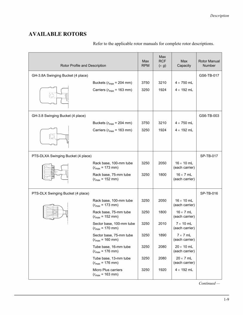
AVAILABLE ROTORS
Refer to the applicable rotor manuals for complete rotor descriptions.
Rotor Profile and DescriptionMax RPM
Max RCF(× g)
MaxCapacity
Rotor ManualNumber
GH-3.8A Swinging Bucket (4 place)
Buckets (rmax = 204 mm)
Carriers (rmax = 163 mm)
3750
3250
3210
1924
4 × 750 mL
4 × 192 mL
GS6-TB-017
GH-3.8 Swinging Bucket (4 place)
Buckets (rmax = 204 mm)
Carriers (rmax = 163 mm)
3750
3250
3210
1924
4 × 750 mL
4 × 192 mL
GS6-TB-003
PTS-DLXA Swinging Bucket (4 place)
Rack base, 100-mm tube(rmax = 173 mm)
Rack base, 75-mm tube(rmax = 152 mm)
3250
3250
2050
1800
16 × 10 mL(each carrier)
16 × 7 mL(each carrier)
SP-TB-017
PTS-DLX Swinging Bucket (4 place)
Rack base, 100-mm tube(rmax = 173 mm)
Rack base, 75-mm tube(rmax = 152 mm)
Sector base, 100-mm tube(rmax = 170 mm)
Sector base, 75-mm tube(rmax = 160 mm)
Tube base, 16-mm tube(rmax = 176 mm)
Tube base, 13-mm tube(rmax = 176 mm)
Micro Plus carriers(rmax = 163 mm)
3250
3250
3250
3250
3250
3250
3250
2050
1800
2010
1890
2080
2080
1920
16 × 10 mL(each carrier)
16 × 7 mL(each carrier)
7 × 10 mL(each carrier)
7 × 7 mL(each carrier)
20 × 10 mL(each carrier)
20 × 7 mL(each carrier)
4 × 192 mL
SP-TB-016
Continued —
1-9
1-10
Description
.
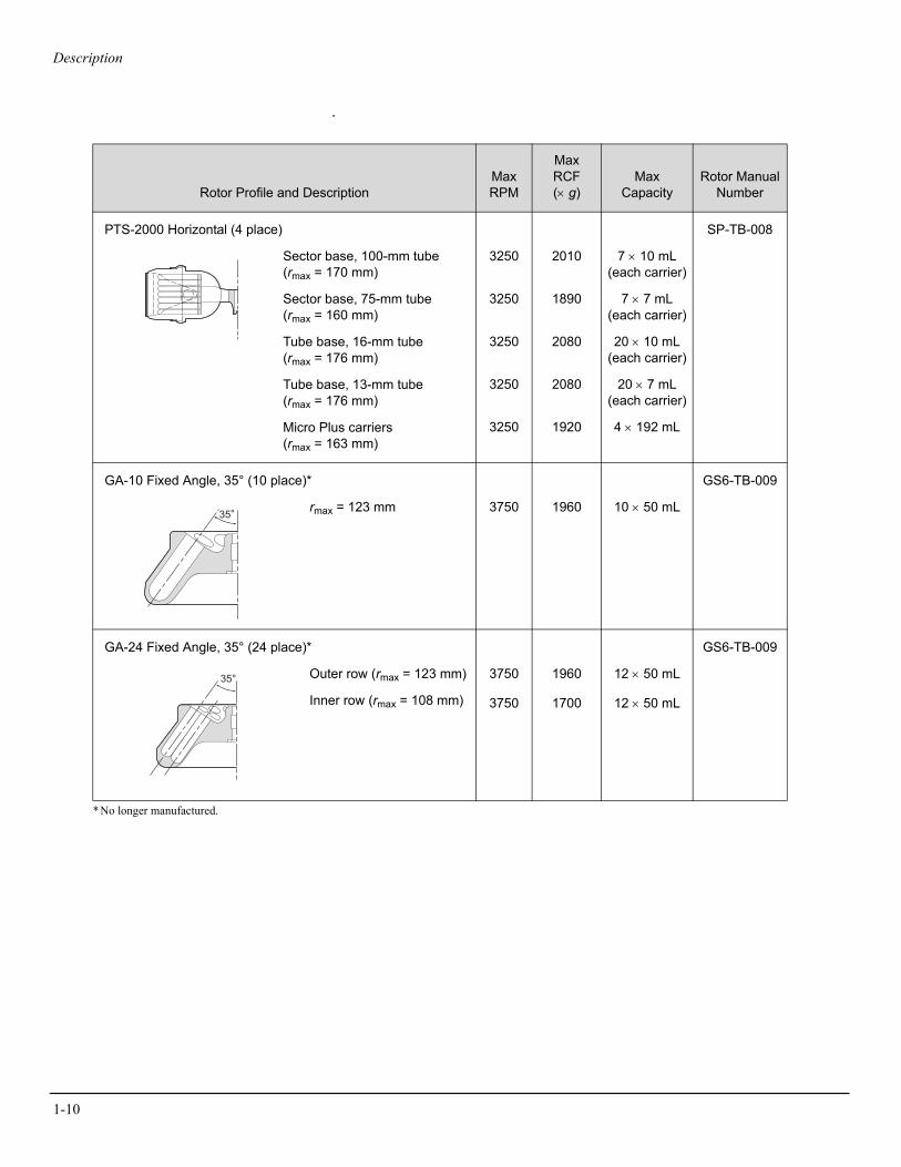
* No longer manufactured.
Rotor Profile and DescriptionMax RPM
Max RCF(× g)
MaxCapacity
Rotor ManualNumber
PTS-2000 Horizontal (4 place)
Sector base, 100-mm tube(rmax = 170 mm)
Sector base, 75-mm tube(rmax = 160 mm)
Tube base, 16-mm tube(rmax = 176 mm)
Tube base, 13-mm tube(rmax = 176 mm)
Micro Plus carriers(rmax = 163 mm)
3250
3250
3250
3250
3250
2010
1890
2080
2080
1920
7 × 10 mL(each carrier)
7 × 7 mL(each carrier)
20 × 10 mL(each carrier)
20 × 7 mL(each carrier)
4 × 192 mL
SP-TB-008
GA-10 Fixed Angle, 35° (10 place)*
rmax = 123 mm 3750 1960 10 × 50 mL
GS6-TB-009
GA-24 Fixed Angle, 35° (24 place)*
Outer row (rmax = 123 mm)
Inner row (rmax = 108 mm)
3750
3750
1960
1700
12 × 50 mL
12 × 50 mL
GS6-TB-009

2Installation Requirements
WARNING!This centrifuge weighs 65.4 kg (144.0 lb). DO NOT attempt to lift or move it without assistance from another person.
INSTALLATION REQUIREMENTS
WARNING!Do not place the centrifuge near areas containing flammable reagents or combustible fluids. Vapors from these materials could enter the centrifuge’s air system and be ignited. Never bring any flammable substances within the 30-cm (1-ft) area surrounding the centrifuge. Maintain a clearance envelope of 7.6 cm (3 in.) around an operating centrifuge. No persons should be within this clearance envelope while the centrifuge is operating.
2-1

2-2
Installation Requirements
SPACE AND LOCATION REQUIREMENTS
Carefully remove the centrifuge and accessories from the shipping container. Save the container and packing materials for possible future relocation or storage of the centrifuge.
• Select a location away from heat-producing laboratory equipment, with sufficient ventilation to allow for heat dissipation.
• Position the centrifuge on a level surface, such as a sturdy table or laboratory bench, which is able to support the weight of the centri-fuge (65.4 kg/144.0 lb) and resist vibration.
• Allow a 7.6-cm (3-in.) clearance at each side and the back of the centrifuge to ensure sufficient air circulation. The centrifuge must have adequate air ventilation to ensure compliance to local requirements for vapors produced during operation. Dimensions are shown in Figure 2-1.
Figure 2-1. Dimensions of the Spinchron DLX Centrifuge
58.423.0
7.63.0
54.621.5
94.037.0
39.415.5
cmin.
IMBALANCEENTER
PULSE
ACCEL
DECEL
RPM RCF ROTORTIME
STOP START
FASTSTOP
OPENDOOR
SPEED
TIME
ACC/DEC
™
®MADE IN U.S.A.

Installation Requirements
• Ambient temperature during operation should not exceed 35°C (95°F). Relative humidity should not exceed 95% (noncondensing).
! CAUTIONUse the anti-rotation kit to secure the centrifuge to the bench or table. The anti-rotation kit is designed to minimize the possibility of injury or damage that could result from centrifuge move-ment in the event of a rotor mishap. Complete instructions (SP-TB-007) for installing the anti-rotation kit are included with the kit, which is shipped with the centrifuge.
ELECTRICAL REQUIREMENTS
100-volt centrifuge. . . . . . . . . . . . . . . . 90–110 VAC, 12 A, 50/60 Hz120-volt centrifuge. . . . . . . . . . . . . . . . . . 108–132 VAC, 10 A, 60 Hz230-volt centrifuge. . . . . . . . . . . . . . . . . 207–253 VAC, 6.3 A, 50 HzElectrical supply . . . . . . . . . . . . . . . . . . . . . . . . . . . . . . . . . . . Class IPower cord . . . . . . . . . . . . . a 1.8-m (6-ft) power cord with grounded
plug is supplied with the centrifuge
➠ NOTEIn regions where a different plug is required to meet local electrical and safety requirements, contact your local Beckman Coulter representative.
Make sure the voltage imprinted on the name rating plate affixed to the back of the centrifuge agrees with the line voltage of the outlet used. With the power switch in the off (O) position, plug in both ends of the centrifuge power cord. If there is any question about voltage, have a qualified service person measure it under load while the drive is operating.
To reduce the risk of electrical shock, this equipment uses a three-wire electrical cord and plug to connect the centrifuge to earth-ground. To preserve this safety feature:
• Make sure that the matching wall outlet receptacle is properly wired and earth-grounded.
2-3
2-4
Installation Requirements
• Never use a three-to-two wire plug adapter.
• Never use a two-wire extension cord or a two-wire non-grounding type of multiple-outlet receptacle strip.
To ensure safety, the centrifuge should be wired to a remote emer-gency switch (preferably outside the room where the centrifuge is housed, or adjacent to the exit from that room), in order to disconnect the centrifuge from the main power source in case of a malfunction.
TEST RUN
➠ NOTEDuring transport between areas with varying temperatures, condensation may occur inside the centrifuge. Allow sufficient drying time before running the centrifuge.
We recommend that you make a test run to ensure that the centrifuge is in proper operating condition after shipment. See Section 3 for instructions on operating the centrifuge.
➠ NOTEAfter completing the test run, return the preaddressed warranty card included with this literature. This will validate the centrifuge warranty and ensure your receipt of further information regarding new accessories and/or modifications as they become available.
NAME RATING PLATE
When corresponding with Beckman Coulter regarding your Spinchron DLX centrifuge, always mention its model and serial number. The serial number is shown on the name rating plate affixed to the rear of the centrifuge, and is also on the inside of the door.
3Operation
This section contains operating procedures for the Spinchron DLX centrifuge, using any of the rotors designed for use in this centrifuge. A summary is provided at the end of this section. If you are an experi-enced user of this centrifuge, you can turn to the summary for a quick review of operating steps. Refer to the applicable rotor manual for instructions on preparing the rotor for centrifugation.
WARNING!The centrifuge must not be used in the vicinity of flammable liquids or vapors, and such materials should not be run in the centrifuge. Never bring any flammable substances within the 30-cm (1-ft) area surrounding the centrifuge. During operation you should not come within the 7.6-cm (3-in.) clearance envelope except to adjust centrifuge controls, if necessary. Do not lean on the centrifuge or place items on the centrifuge while it is operating.
WARNING!Operator error or tube failure may generate aerosols. Use only the appropriate rotors and adapters. Do not run toxic, pathogenic, or radioactive materials in this centrifuge without taking appropriate safety pre-cautions. Biosafe hoods should be used when Risk Group II materials (as identified in the World Health Organization Laboratory Biosafety Manual) are handled; materials of a higher group require more than one level of protection.
3-1
3-2
Operation
RUN PREPARATION
The following detailed operating procedures are summarized at the end of this section. If you are an experienced user of this centrifuge, you can turn to the summary for a quick review of operating steps. Refer to the applicable rotor manual for instructions on preparing the rotor for centrifugation.
Action Result
1. Ensure that the power cord is plugged into a wall receptacle that provides the correct voltage.
Power is available to the centrifuge.
2. Press the power switch to on (I).
Power is applied to the system and displays are lit.
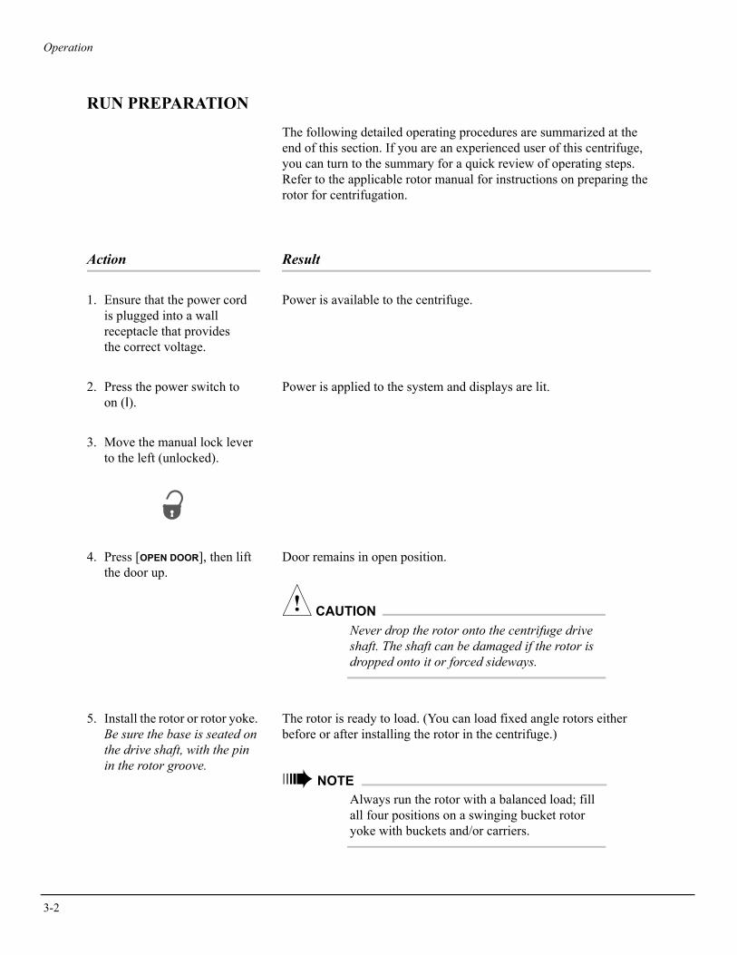
3. Move the manual lock lever to the left (unlocked).
4. Press [OPEN DOOR], then lift the door up.
Door remains in open position.
! CAUTIONNever drop the rotor onto the centrifuge drive shaft. The shaft can be damaged if the rotor is dropped onto it or forced sideways.
5. Install the rotor or rotor yoke. Be sure the base is seated on the drive shaft, with the pin in the rotor groove.
The rotor is ready to load. (You can load fixed angle rotors either before or after installing the rotor in the centrifuge.)
➠ NOTEAlways run the rotor with a balanced load; fill all four positions on a swinging bucket rotor yoke with buckets and/or carriers.
Operation
Action Result
6. Load the rotor according to the rotor manual.
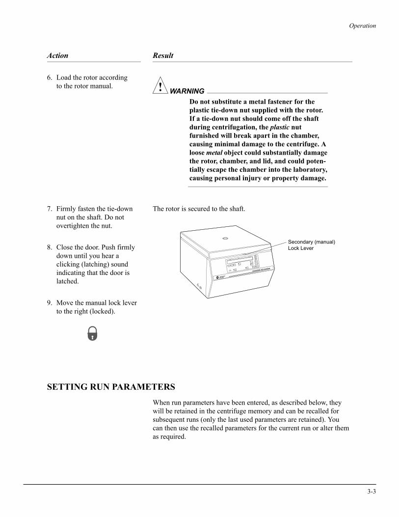
WARNING!Do not substitute a metal fastener for the plastic tie-down nut supplied with the rotor. If a tie-down nut should come off the shaft during centrifugation, the plastic nut furnished will break apart in the chamber, causing minimal damage to the centrifuge. A loose metal object could substantially damage the rotor, chamber, and lid, and could poten-tially escape the chamber into the laboratory, causing personal injury or property damage.
7. Firmly fasten the tie-down nut on the shaft. Do not overtighten the nut.
The rotor is secured to the shaft.
8. Close the door. Push firmly down until you hear a clicking (latching) sound indicating that the door is latched.
9. Move the manual lock lever to the right (locked).
SETTING RUN PARAMETERS
When run parameters have been entered, as described below, they will be retained in the centrifuge memory and can be recalled for subsequent runs (only the last used parameters are retained). You can then use the recalled parameters for the current run or alter them as required.
Secondary (manual)Lock Lever
IMBALANCE
ENTER
PULSEACCEL
DECEL
RPM RCF ROTORTIME
STOP STARTFASTSTOP
OPENDOOR
SPEED
TIME
ACC/DEC
™
®
MADE IN U.S.A.
3-3
3-4
Operation
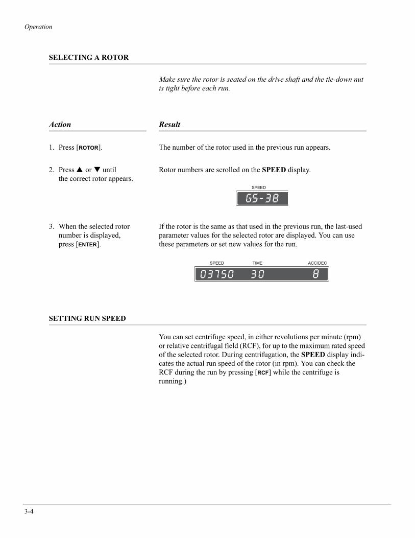
SELECTING A ROTOR
Make sure the rotor is seated on the drive shaft and the tie-down nut is tight before each run.
Action Result
1. Press [ROTOR]. The number of the rotor used in the previous run appears.
2. Press ▲ or ▼ until the correct rotor appears.
Rotor numbers are scrolled on the SPEED display.
3. When the selected rotor number is displayed, press [ENTER].
If the rotor is the same as that used in the previous run, the last-used parameter values for the selected rotor are displayed. You can use these parameters or set new values for the run.
SETTING RUN SPEED
You can set centrifuge speed, in either revolutions per minute (rpm) or relative centrifugal field (RCF), for up to the maximum rated speed of the selected rotor. During centrifugation, the SPEED display indi-cates the actual run speed of the rotor (in rpm). You can check the RCF during the run by pressing [RCF] while the centrifuge is running.)
SPEED
SPEED TIME ACC/DEC
Operation
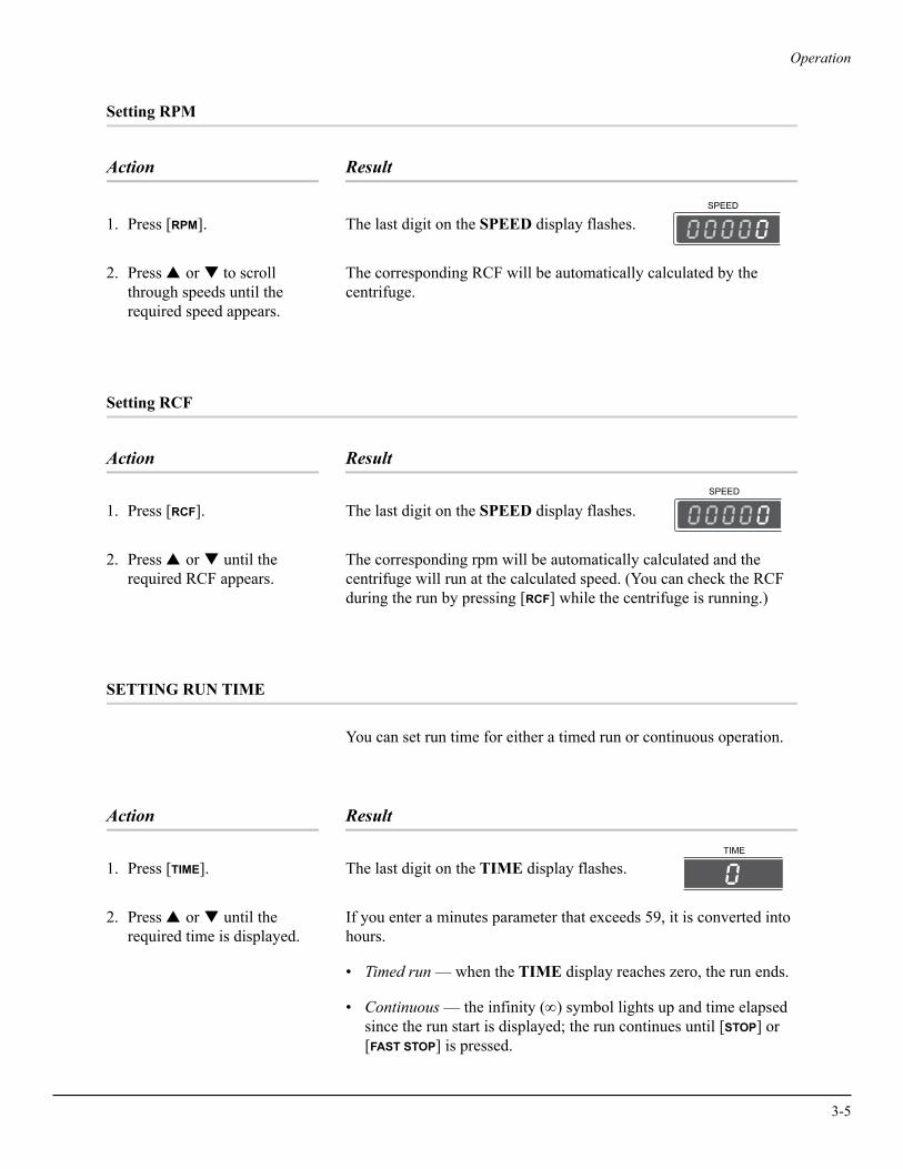
Setting RPM
Action Result
1. Press [RPM]. The last digit on the SPEED display flashes.
2. Press ▲ or ▼ to scroll through speeds until the required speed appears.
The corresponding RCF will be automatically calculated by the centrifuge.
Setting RCF
Action Result
1. Press [RCF]. The last digit on the SPEED display flashes.
2. Press ▲ or ▼ until the required RCF appears.
The corresponding rpm will be automatically calculated and the centrifuge will run at the calculated speed. (You can check the RCF during the run by pressing [RCF] while the centrifuge is running.)
SETTING RUN TIME
You can set run time for either a timed run or continuous operation.
Action Result
1. Press [TIME]. The last digit on the TIME display flashes.
2. Press ▲ or ▼ until the required time is displayed.
If you enter a minutes parameter that exceeds 59, it is converted into hours.
• Timed run — when the TIME display reaches zero, the run ends.
• Continuous — the infinity (∞) symbol lights up and time elapsed since the run start is displayed; the run continues until [STOP] or [FAST STOP] is pressed.
SPEED
SPEED
TIME
3-5

3-6
Operation
SETTING ACCELERATION AND DECELERATION RATES
You can select one of nine acceleration and nine deceleration rates that will maintain optimum separation of delicate samples. Select rates depending on the type of run you are performing—for pelleting runs, where sample mixing is not a concern, maximum brake can be used. If running delicate gradients, a lower brake setting may be needed. Acceleration and deceleration rates are listed in Table 3-1.
Table 3-1. Acceleration and Deceleration Rates (in Minutes:Seconds) to and from Maximum Speed. Times shown are for the rotor’s maximum speed with the rotor fully loaded. (Times are approximate;
actual times will vary depending on the rotor load, run speed, and voltage fluctuations.)
Setting an Acceleration Rate
Action Result
1. Press [ACCEL]. The ACC/DEC display flashes.
2. Press ▲ or ▼ until the selected rate is displayed.
Accel/DecelRate
GS-3.8 GS-3.8A PTS-DLX GA-10 or GA-24
Accel Decel Accel Decel Accel Decel Accel Decel
987
1:151:201:23
0:420:440:48
2:302:342:37
1:201:231:27
0:440:460:50
0:270:310:36
0:180:230:39
0:180:210:40
654
1:332:002:37
1:181:552:31
2:462:523:29
1:462:233:39
1:121:432:15
1:081:402:12
1:181:572:34
1:181:532:32
321
3:527:30
11:22
3:487:30
11:16
4:448:22
12:14
4:568:38
12:24
3:196:339:50
3:176:319:46
3:497:34
11:19
3:467:31
11:15
ACC/DEC
Operation
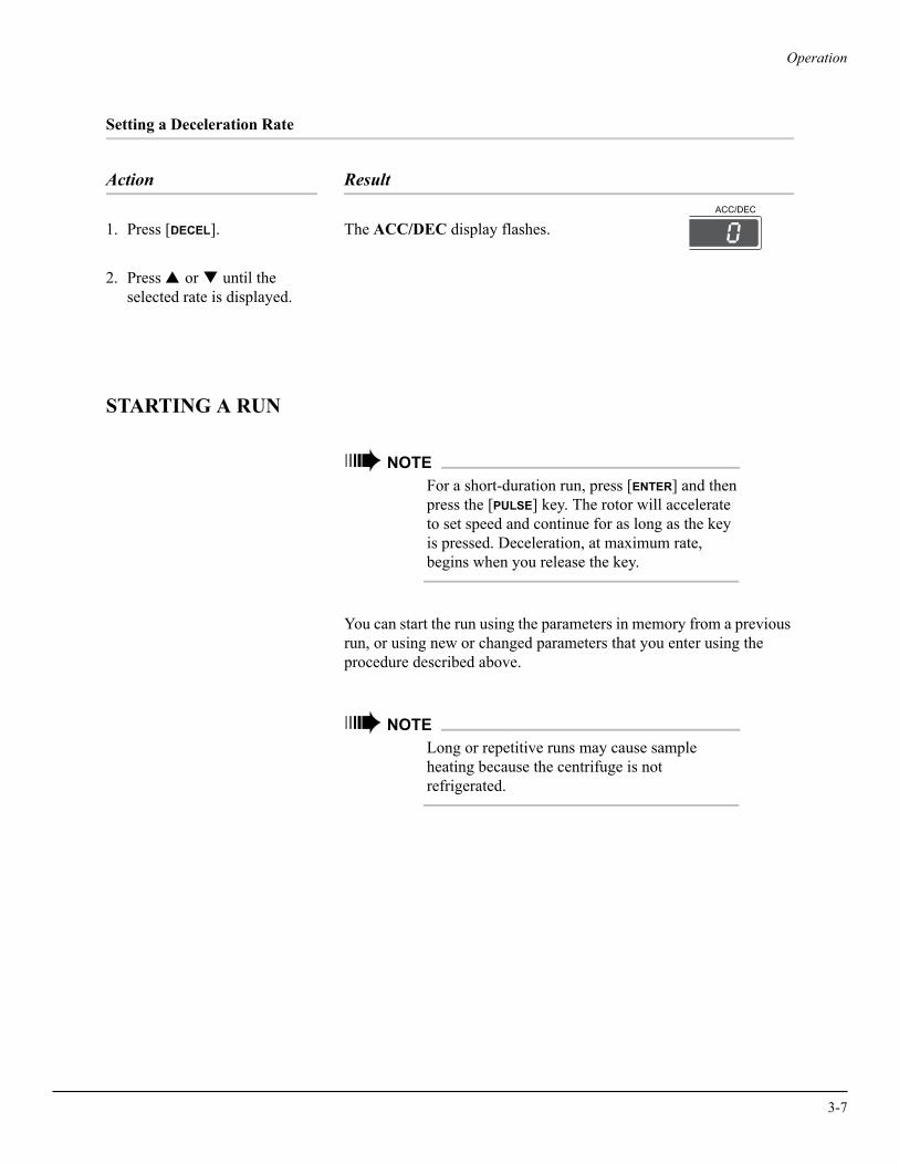
Setting a Deceleration Rate
Action Result
1. Press [DECEL]. The ACC/DEC display flashes.
2. Press ▲ or ▼ until the selected rate is displayed.
STARTING A RUN
➠ NOTEFor a short-duration run, press [ENTER] and then press the [PULSE] key. The rotor will accelerate to set speed and continue for as long as the key is pressed. Deceleration, at maximum rate, begins when you release the key.
You can start the run using the parameters in memory from a previous run, or using new or changed parameters that you enter using the procedure described above.
➠ NOTELong or repetitive runs may cause sample heating because the centrifuge is not refrigerated.
ACC/DEC
3-7

3-8
Operation
Action Result
1. Check that all parameters are correct and the door is closed.
! CAUTIONDo not lift or move the centrifuge while the rotor is spinning.
2. Move the manual lock lever to the right (locked position).
3. Press [ENTER], then press [START].
• The SPEED display indicates rotor speed in rpm. (You can check the RCF by pressing the [RCF] key.)
• A blinking LED at the bottom of the TIME display indicates that the run is in progress. This display also shows the remaining run time (in hours and minutes) for a timed run; or the infinity (∞) symbol and time elapsed since the run start. (When elapsed time reaches 9 hours and 59 minutes during a continuous run, it resets to 0 and continues counting.)
• The ACC/DEC display shows the deceleration rate selected for the run.
WARNING!Do not attempt to override the door interlock system while the rotor is spinning.
CHANGING PARAMETERS DURING A RUN
While a run is in progress, run parameters (speed, time, and decelera-tion rate) can be altered without stopping the run. Run duration can also be changed from continuous to a specified time period, or from a specified time period to continuous.
Operation
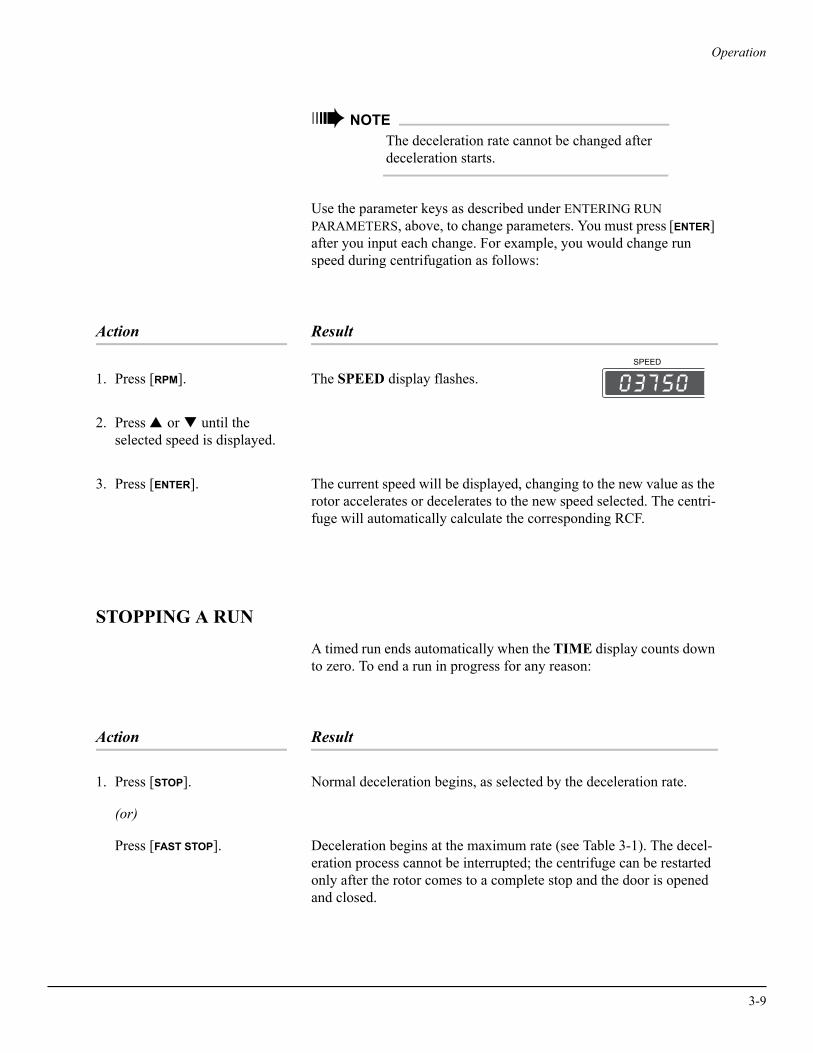
➠ NOTEThe deceleration rate cannot be changed after deceleration starts.
Use the parameter keys as described under ENTERING RUN PARAMETERS, above, to change parameters. You must press [ENTER] after you input each change. For example, you would change run speed during centrifugation as follows:
Action Result
1. Press [RPM]. The SPEED display flashes.
2. Press ▲ or ▼ until the selected speed is displayed.
3. Press [ENTER]. The current speed will be displayed, changing to the new value as the rotor accelerates or decelerates to the new speed selected. The centri-fuge will automatically calculate the corresponding RCF.
STOPPING A RUN
A timed run ends automatically when the TIME display counts down to zero. To end a run in progress for any reason:
Action Result
1. Press [STOP]. Normal deceleration begins, as selected by the deceleration rate.
(or)
Press [FAST STOP]. Deceleration begins at the maximum rate (see Table 3-1). The decel-eration process cannot be interrupted; the centrifuge can be restarted only after the rotor comes to a complete stop and the door is opened and closed.
SPEED
3-9

3-10
Operation
Action Result
2. After the rotor stops spinning and the [OPEN DOOR] light comes on, move the manual lock lever to the left (unlocked).
! CAUTIONThe door interlock system will release the latch and allow the door to be opened when the rotor speed is 40 rpm or less. However, for operator safety, do not open the door until the rotor has come to a complete stop. Additionally, do not attempt to override the door interlock system while the rotor is spinning.
3. Press [OPEN DOOR], then lift the door up.
UNLOADING
! CAUTIONIf disassembly reveals evidence of leakage, you should assume that some fluid escaped the rotor. Apply appropriate decontamination procedures to the centrifuge and accessories.
After completing a run, unload the rotor as described in the applicable rotor manual. It is not necessary to remove the rotor from the centri-fuge between runs unless the rotor or chamber bowl needs to be cleaned. (If the rotor is left in the centrifuge between runs, make sure the rotor is seated on the drive shaft and the tie-down nut is tight before each run.)
➠ NOTEAccumulations of sample, dust, and/or glass particles from broken sample tubes can ruin rotor pins and cause rotor vibrations. To prevent these accumulations, remove the rotor and clean the centrifuge bowl daily. See CLEANING in Section 5.
Operation
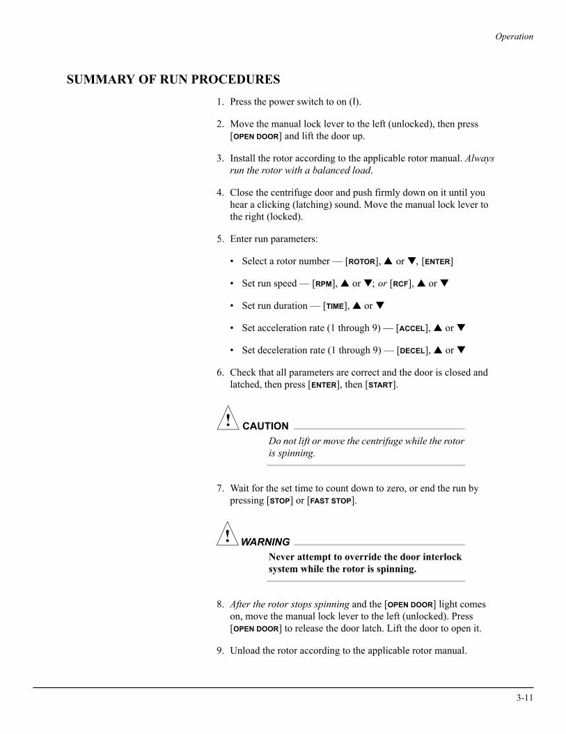
SUMMARY OF RUN PROCEDURES
1. Press the power switch to on (I).
2. Move the manual lock lever to the left (unlocked), then press [OPEN DOOR] and lift the door up.
3. Install the rotor according to the applicable rotor manual. Always run the rotor with a balanced load.
4. Close the centrifuge door and push firmly down on it until you hear a clicking (latching) sound. Move the manual lock lever to the right (locked).
5. Enter run parameters:
• Select a rotor number — [ROTOR], ▲ or ▼, [ENTER]
• Set run speed — [RPM], ▲ or ▼; or [RCF], ▲ or ▼
• Set run duration — [TIME], ▲ or ▼
• Set acceleration rate (1 through 9) — [ACCEL], ▲ or ▼
• Set deceleration rate (1 through 9) — [DECEL], ▲ or ▼
6. Check that all parameters are correct and the door is closed and latched, then press [ENTER], then [START].
! CAUTIONDo not lift or move the centrifuge while the rotor is spinning.
7. Wait for the set time to count down to zero, or end the run by pressing [STOP] or [FAST STOP].
WARNING!Never attempt to override the door interlock system while the rotor is spinning.
8. After the rotor stops spinning and the [OPEN DOOR] light comes on, move the manual lock lever to the left (unlocked). Press [OPEN DOOR] to release the door latch. Lift the door to open it.
9. Unload the rotor according to the applicable rotor manual.
3-11


4Troubleshooting
This section lists possible malfunctions, together with probable causes and corrective actions required. Maintenance procedures are contained in Section 5. For any problems not covered here contact Beckman Coulter Field Service.
➠ NOTEIt is your responsibility to decontaminate the centrifuge, as well as any accessories, before requesting service by Beckman Coulter Field Service representatives.
USER MESSAGES
! CAUTIONIf the message SEr appears on the display, do not press any keys while the message is displayed. Turn the centrifuge power off (O) and back on (I) to clear the message. This message indicates that you have inadvertently accessed the service mode; pressing any keys while in this mode could erase the centrifuge memory and critically interfere with future operation.
If a problem occurs during operation, the rotor will decelerate to a stop and an error code will appear on the SPEED display. Messages may result from incorrect input (such as exceeding allowable speed for a rotor) or from an equipment malfunction. Refer to Table 4-1 to
4-1
4-2
Troubleshooting
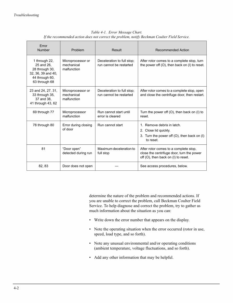
Table 4-1. Error Message Chart. If the recommended action does not correct the problem, notify Beckman Coulter Field Service.
determine the nature of the problem and recommended actions. If you are unable to correct the problem, call Beckman Coulter Field Service. To help diagnose and correct the problem, try to gather as much information about the situation as you can:
• Write down the error number that appears on the display.
• Note the operating situation when the error occurred (rotor in use, speed, load type, and so forth).
• Note any unusual environmental and/or operating conditions (ambient temperature, voltage fluctuations, and so forth).
• Add any other information that may be helpful.
ErrorNumber Problem Result Recommended Action
1 through 22,25 and 26,
28 through 30,32, 36, 39 and 40,
44 through 60,63 through 68
Microprocessor or mechanical malfunction
Deceleration to full stop; run cannot be restarted
After rotor comes to a complete stop, turn the power off (O), then back on (I) to reset.
23 and 24, 27, 31,33 through 35,
37 and 38,41 through 43, 62
Microprocessor or mechanical malfunction
Deceleration to full stop; run cannot be restarted
After rotor comes to a complete stop, open and close the centrifuge door, then restart.
69 through 77 Microprocessor malfunction
Run cannot start until error is cleared
Turn the power off (O), then back on (I) to reset.
78 through 80 Error during closing of door
Run cannot start 1. Remove debris in latch.2. Close lid quickly.3. Turn the power off (O), then back on (I)
to reset.
81 “Door open”detected during run
Maximum deceleration to full stop
After rotor comes to a complete stop, close the centrifuge door, turn the power off (O), then back on (I) to reset.
82, 83 Door does not open — See access procedures, below.

Troubleshooting
OTHER POSSIBLE PROBLEMS
Possible malfunctions that may not be indicated by diagnostic messages are described in Table 4-2, along with probable causes and corrective actions required. Possible causes for each problem are listed in the probable order of occurrence. Perform the recommended corrective action in sequence, as listed. If you are unable to correct the problem, call Beckman Coulter Field Service.
Table 4-2. Troubleshooting Chart
Problem Problem/Result Recommended Action
Imbalance LED lights and rotor decelerates to stop
1. Rotor is out of balance
2. Centrifuge is misaligned (tilted)
3. Centrifuge was moved during operation
4. Drive error (mechanical damage)
1. Check to be sure the rotor is in good condition and is loaded symmetrically around the center of rotation, with containers of equal weight and density (within 6 grams) opposite each other.
2. Align the centrifuge on the bench or table.
3. After the rotor comes to a complete stop, open and close the centrifuge door, then restart.
4. Call Beckman Coulter Field Service.
Rotor cannot achieve set speed
1. Line voltage below rating
2. Electrical failure
3. Motor failure
1. Have a qualified service person measure line voltage while the instrument is operating.
2. Make sure both ends of the power cord are securely connected; call Beckman Coulter Field Service
3. Call Beckman Coulter Field Service.
Door will not open 1. Rotor spinning2. Manual lock lever in locked
position.3. Power not on4. Source power failure5. Latch stuck
1. Wait until the rotor stops.2. Move the lever to the left (unlocked).
3. Plug in the power cord; turn power on (I).4. See access procedures, below.5. See access procedures, below.
Displays are blank 1. Power not on2. Electrical failure
3. Fuse blown
1. Plug in the power cord; turn power on (I).2. Make sure both ends of the power cord are
securely connected; call Beckman Coulter Field Service.
3. Call Beckman Coulter Field Service.
4-3
4-4
Troubleshooting
ACCESSING THE ROTOR IN CASE OF POWER FAILURE
If the facility power fails only momentarily, the centrifuge will resume operation when power is restored and the rotor will return to set speed. However, if the rotor comes to a complete stop you will have to restart the run when the power is restored. In the event of an extended power failure, it may be necessary to trip the door-locking mechanism manually to remove the rotor and retrieve your sample.
Action Result
1. Turn the power switch to off (O) and disconnect the power cord from the main power source.
No displays or LEDs are lit.
2. Make sure that the rotor is not spinning.
No sound or vibration comes from the centrifuge.
WARNING!Never attempt to override the door interlock system while the rotor is spinning.
3. Move the manual lock lever to the left (unlocked).
Troubleshooting
Action Result
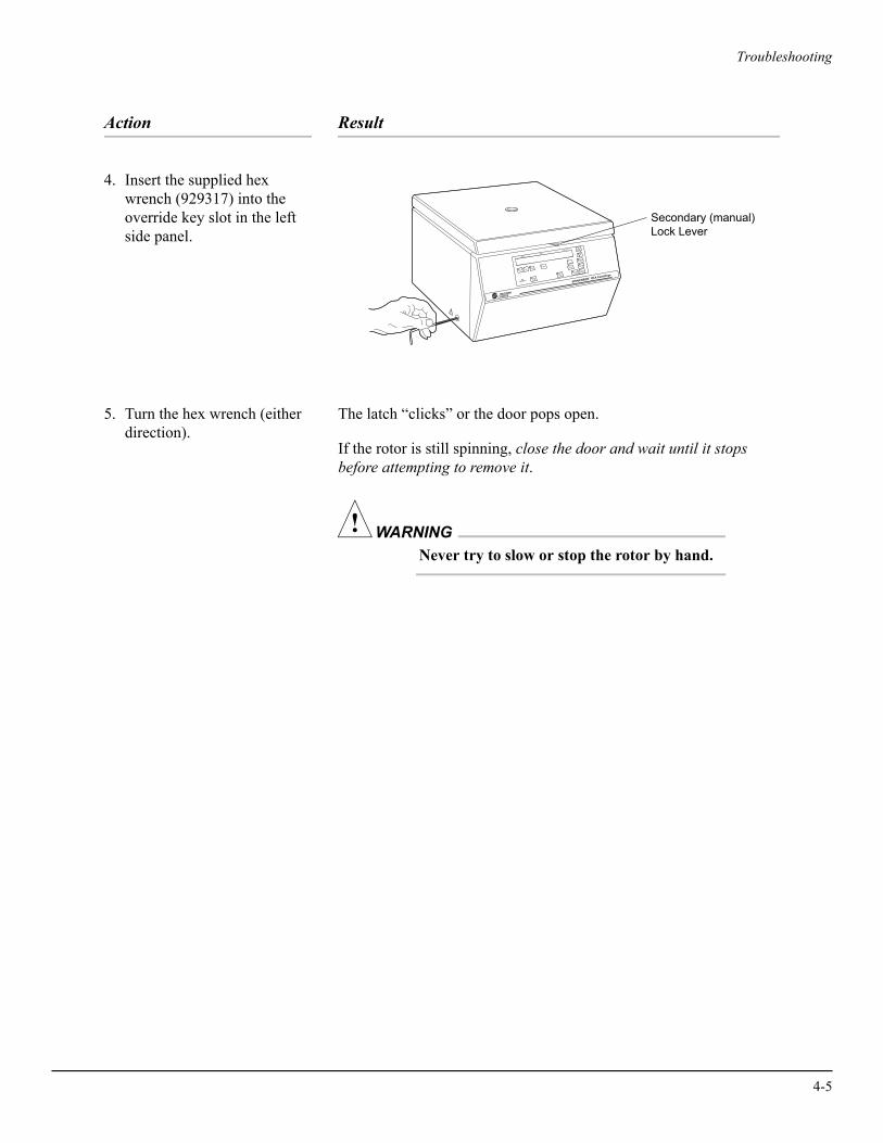
4. Insert the supplied hexwrench (929317) into theoverride key slot in the leftside panel.
5. Turn the hex wrench (either direction).
The latch “clicks” or the door pops open.
If the rotor is still spinning, close the door and wait until it stops before attempting to remove it.
WARNING!Never try to slow or stop the rotor by hand.
IMBALANCE
ENTER
PULSEACCEL
DECEL
RPM RCF ROTORTIME
STOP STARTFASTSTOP
OPENDOOR
SPEED
TIME
ACC/DEC
Secondary (manual)Lock Lever
™
®
MADE IN U.S.A.
4-5

5Care and Maintenance
For maintenance not covered in this manual, contact Beckman Coulter Field Service.
WARNING!Any maintenance procedure or servicing of this equipment that requires removal of any covers can expose parts that involve the risk of electric shock or personal injury. Make sure that the power switch is off (O) and the centrifuge is disconnected from the main power source, and refer such servicing to qualified personnel.
GENERAL MAINTENANCE
Perform the following procedures regularly to ensure satisfactory performance and long service life of the centrifuge.
• At least once a week (depending on usage) inspect the interior of the rotor chamber for accumulations of sample, dust, and glass particles from broken sample tubes. Clean as required (see CLEANING, below), as these accumulations can result in rotor vibrations.
• Regularly check the air intake and exhaust vents for obstructions. Keep vents clear and clean.
5-1
5-2
Care and Maintenance
• To prevent the rotor from sticking, lubricate the drive shaft with Spinkote (306812) at least once a month, and after each cleaning.
• Refer to the applicable rotor manual for instructions on the care of rotors and other components and accessories.
➠ NOTEBefore using any cleaning or decontamination methods except those recommended by the manufacturer, users should check with the manufacturer that the proposed method will not damage the equipment.
CLEANING
Frequent cleaning will ensure proper operation and prolong the life of the centrifuge. Always clean up spills when they occur to prevent corrosives or contaminants from drying on component surfaces.
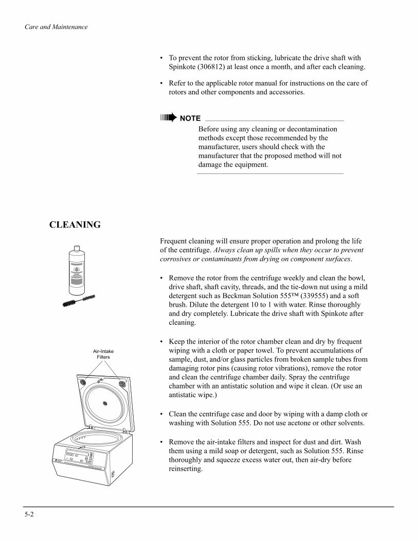
• Remove the rotor from the centrifuge weekly and clean the bowl, drive shaft, shaft cavity, threads, and the tie-down nut using a mild detergent such as Beckman Solution 555™ (339555) and a soft brush. Dilute the detergent 10 to 1 with water. Rinse thoroughly and dry completely. Lubricate the drive shaft with Spinkote after cleaning.
• Keep the interior of the rotor chamber clean and dry by frequent wiping with a cloth or paper towel. To prevent accumulations of sample, dust, and/or glass particles from broken sample tubes from damaging rotor pins (causing rotor vibrations), remove the rotor and clean the centrifuge chamber daily. Spray the centrifuge chamber with an antistatic solution and wipe it clean. (Or use an antistatic wipe.)
• Clean the centrifuge case and door by wiping with a damp cloth or washing with Solution 555. Do not use acetone or other solvents.
• Remove the air-intake filters and inspect for dust and dirt. Wash them using a mild soap or detergent, such as Solution 555. Rinse thoroughly and squeeze excess water out, then air-dry before reinserting.
IMBALANCEENTER
PULSE
ACCEL
DECEL
RPM RCF ROTORTIME
STOP START
FASTSTOP
OPENDOOR
SPEED
TIME
ACC/DEC
™
®MADE IN U.S.A.
Air-IntakeFilters

Care and Maintenance
DECONTAMINATION
If the centrifuge and/or accessories are contaminated with radioactive or pathogenic solutions, perform appropriate decontamination proce-dures. Refer to Chemical Resistances (publication IN-175) to be sure the decontamination method will not damage any part of the centrifuge.
STERILIZATION AND DISINFECTION
The centrifuge is finished with urethane paint. Ethanol (70%)* may be used on this surface. See Chemical Resistances for more informa-tion regarding chemical resistance of centrifuge and accessory materials.
While Beckman Coulter has tested this method and found that it does not damage the centrifuge, no guarantee of sterility or disinfection is expressed or implied. When sterilization or disinfection is a concern, consult your laboratory safety officer regarding proper methods to use.
TUBE BREAKAGEIf a glass tube breaks, and all the glass is not contained in the bucket or rotor, thoroughly clean the interior of the chamber bowl.
! CAUTIONBe careful when examining or cleaning the gasket or chamber, as sharp glass fragments may be embedded in their surfaces.
• Examine the gasket to make sure that it is free of glass particles. Carefully remove any glass particles that may remain. If glass is under the gasket, call Beckman Coulter Field Service to replace the gasket.
• Carefully wipe away any glass particles that remain in the bowl.
* Flammability hazard. Do not use in or near an operating centrifuge.
5-3

5-4
Care and Maintenance
STORAGE AND TRANSPORT
If you are shipping both the centrifuge and a rotor, remove the rotor from the centrifuge and pack it in its original shipping container. A rotor left in the centrifuge can bend the drive shaft if the package is jarred during shipment.
STORAGE
Before storing a centrifuge for an extended period remove the rotor. Return the centrifuge to its original shipping container to protect it from dust and dirt. Temperature and humidity conditions for storage should meet the operating environment requirements described under SPECIFICATIONS in Section 1.
RETURNING A CENTRIFUGE
Before returning a centrifuge or accessory for any reason, prior permission (a Returned Goods Authorization form) must be obtained from Beckman Coulter, Inc. Contact your local Beckman Coulter office to obtain the RGA form and for packaging and shipping instructions.
To protect our personnel, it is the customer’s responsibility to ensure that all parts are free from pathogens and/or radioactivity. Steriliza-tion and decontamination must be done before returning the parts.
All parts must be accompanied by a note, plainly visible on the out-side of the box, stating that they are safe to handle and that they are not contaminated with pathogens or radioactivity. Failure to attach this notification will result in return or disposal of the items without review of the reported problem.
RGA

Care and Maintenance
SUPPLY LIST
➠ NOTEPublications referenced in this manual can be obtained by calling Beckman Coulter at 1-800-742-2345 in the United States, or by contacting your local Beckman Coulter office.
Contact Beckman Coulter Sales (1-800-742-2345 in the United States; worldwide offices are listed at the back of this manual) for information about ordering parts and supplies. For your convenience, a partial list is given below.
REPLACEMENT PARTS
Neoprene boot . . . . . . . . . . . . . . . . . . . . . . . . . . . . . . . . . . . . . . . . . . . 358009Rotor tie-down nut . . . . . . . . . . . . . . . . . . . . . . . . . . . . . . . . . . . . . . . 366642Tie-down nut O-ring (Buna N rubber) . . . . . . . . . . . . . . . . . . . . . . . . 927600Torquing bar . . . . . . . . . . . . . . . . . . . . . . . . . . . . . . . . . . . . . . . . . . . . 356036Hex wrench (latch release) . . . . . . . . . . . . . . . . . . . . . . . . . . . . . . . . . 929317Power cord (60-Hz, 120 VAC) . . . . . . . . . . . . . . . . . . . . . . . . . . . . . . 889097Power cord (50-Hz, 230 VAC) . . . . . . . . . . . . . . . . . . . . . . . . . . . . . . 355810
SUPPLIES
Spinkote lubricant (2 oz) . . . . . . . . . . . . . . . . . . . . . . . . . . . . . . . . . . . 306812Silicone vacuum grease (1 oz) . . . . . . . . . . . . . . . . . . . . . . . . . . . . . . 335148Beckman Solution 555 (1 qt) . . . . . . . . . . . . . . . . . . . . . . . . . . . . . . . 339555Magnetized document holder . . . . . . . . . . . . . . . . . . . . . . . . . . . . . . . 964987
5-5


SPINCHRON DLX CENTRIFUGE WARRANTY
Subject to the exceptions and upon the conditions specifiedbelow and the warranty clause of the Beckman Coulter termsand conditions in effect at the time of sale, Beckman Coulteragrees to correct either by repair or, at its election, by replace-ment, any defects of material or workmanship which developwithin one (1) year after delivery of a SPINCHRON DLXcentrifuge (the product), to the original buyer by BeckmanCoulter or by an authorized representative, provided thatinvestigation and factory inspection by Beckman Coulterdiscloses that such defect developed under normal and properuse.
Some components and accessories by their nature are notintended to and will not function for as long as one (1) year. Acomplete list of such components or accessories is maintainedat the factory and at each Beckman Coulter District SalesOffice. The lists applicable to the products sold hereundershall be deemed to be part of this warranty. If any such com-ponent or accessory fails to give reasonable service for a rea-sonable period of time, Beckman Coulter will repair or, at itselection, replace such component or accessory. What consti-tutes either reasonable service and a reasonable period of timeshall be determined solely by Beckman Coulter.
REPLACEMENT
Any product claimed to be defective must, if requested byBeckman Coulter, be returned to the factory, transportationcharges prepaid, and will be returned to Buyer with the trans-portation charges collect unless the product is found to bedefective, in which case Beckman Coulter will pay all trans-portation charges.
CONDITIONS
Beckman Coulter makes no warranty concerning products oraccessories not manufactured by it. In the event of failure ofany such product or accessory, Beckman Coulter will givereasonable assistance to the Buyer in obtaining from therespective manufacturer whatever adjustment is reasonable inlight of the manufacturer’s own warranty.
Beckman Coulter shall be released from all obligations underall warranties, either expressed or implied, if the product(s)covered hereby are repaired or modified by persons otherthan its own authorized service personnel, unless such repairin the sole opinion of Beckman Coulter is minor, or unlesssuch modification is merely the installation of a new Beck-man Coulter plug-in component for such product(s).
DISCLAIMER
IT IS EXPRESSLY AGREED THAT THE ABOVE WAR-RANTY SHALL BE IN LIEU OF ALL WARRANTIES OFFITNESS AND OF THE WARRANTY OF MERCHANT-ABILITY AND THAT NEITHER BECKMAN COULTER,INC. NOR ITS SUPPLIERS SHALL HAVE ANYLIABILITY FOR SPECIAL OR CONSEQUENTIALDAMAGES OF ANY KIND WHATSOEVER ARISINGOUT OF THE MANUFACTURE, USE, SALE, HAN-DLING, REPAIR, MAINTENANCE, OR REPLACEMENTOF THE PRODUCT.


Beckman Coulter, Inc. • 250 S. Kraemer Blvd. • Brea, California 92821Sales and Service: 1-800-742-2345 • Internet: www.beckmancoulter.com
©2009 Beckman Coulter, Inc.All rights reserved


![Centrifuga revista[1]](https://static.fdocuments.net/doc/165x107/5585c847d8b42ab2048b4a1d/centrifuga-revista1.jpg)