Centralized Rate Allocation and Control in 802.11-based Wireless
176
Centralized Rate Allocation and Control in 802.11-based Wireless Mesh Networks by Kamran Jamshaid A thesis presented to the University of Waterloo in fulfillment of the thesis requirement for the degree of Doctor of Philosophy in Electrical and Computer Engineering Waterloo, Ontario, Canada, 2010 c Kamran Jamshaid 2010
Transcript of Centralized Rate Allocation and Control in 802.11-based Wireless

Centralized Rate Allocation
and Control in 802.11-based
Wireless Mesh Networks
by
Kamran Jamshaid
A thesis
presented to the University of Waterloo
in fulfillment of the
thesis requirement for the degree of
Doctor of Philosophy
in
Electrical and Computer Engineering
Waterloo, Ontario, Canada, 2010
c© Kamran Jamshaid 2010

I hereby declare that I am the sole author of this thesis. This is a true copy of the
thesis, including any required final revisions, as accepted by my examiners.
I understand that my thesis may be made electronically available to the public.
ii

Abstract
Wireless Mesh Networks (WMNs) built with commodity 802.11 radios are a
cost-effective means of providing last mile broadband Internet access. Their multi-
hop architecture allows for rapid deployment and organic growth of these networks.
802.11 radios are an important building block in WMNs. These low cost ra-
dios are readily available, and can be used globally in license-exempt frequency
bands. However, the 802.11 Distributed Coordination Function (DCF) medium
access mechanism does not scale well in large multihop networks. This produces
suboptimal behavior in many transport protocols, including TCP, the dominant
transport protocol in the Internet. In particular, cross-layer interaction between
DCF and TCP results in flow level unfairness, including starvation, with back-
logged traffic sources. Solutions found in the literature propose distributed source
rate control algorithms to alleviate this problem. However, this requires MAC-layer
or transport-layer changes on all mesh routers. This is often infeasible in practical
deployments.
In wireline networks, router-assisted rate control techniques have been proposed
for use alongside end-to-end mechanisms. We evaluate the feasibility of establish-
ing similar centralized control via gateway mesh routers in WMNs. We find that
commonly used router-assisted flow control schemes designed for wired networks
fail in WMNs. This is because they assume that: (1) links can be scheduled in-
dependently, and (2) router queue buildups are sufficient for detecting congestion.
These abstractions do not hold in a wireless network, rendering wired scheduling al-
gorithms such as Fair Queueing (and its variants) and Active Queue Management
(AQM) techniques ineffective as a gateway-enforceable solution in a WMN. We
show that only non-work-conserving rate-based scheduling can effectively enforce
rate allocation via a single centralized traffic-aggregation point.
In this context we propose, design, and evaluate a framework of centralized,
measurement-based, feedback-driven mechanisms that can enforce a rate allocation
policy objective for adaptive traffic streams in a WMN. In this dissertation we focus
on fair rate allocation requirements. Our approach does not require any changes to
individual mesh routers. Further, it uses existing data traffic as capacity probes,
thus incurring a zero control traffic overhead. We propose two mechanisms based
on this approach: aggregate rate control (ARC) and per-flow rate control (PFRC).
ARC limits the aggregate capacity of a network to the sum of fair rates for a given
set of flows. We show that the resulting rate allocation achieved by DCF is approx-
imately max-min fair. PFRC allows us to exercise finer-grained control over the
iii

rate allocation process. We show how it can be used to achieve weighted flow rate
fairness. We evaluate the performance of these mechanisms using simulations as
well as implementation on a multihop wireless testbed. Our comparative analysis
show that our mechanisms improve fairness indices by a factor of 2 to 3 when com-
pared with networks without any rate limiting, and are approximately equivalent
to results achieved with distributed source rate limiting mechanisms that require
software modifications on all mesh routers.
iv

Acknowledgements
In the name of Allah, the most Beneficent, the most Merciful
I wish to thank my adviser Prof. Paul Ward for taking me under his tutelage
and for providing me this opportunity to work with him. I have benefited from his
advice on many aspects of this research, whether it was helping me think through
a problem, or his painstakingly-detailed feedback on various drafts of my writing. I
am grateful to him for demanding high standards of scientific rigor in our research,
and for his patience, understanding, and help in working with me at times when I
would fall short of those exacting requirements.
I thank Prof. Sagar Naik, Prof. Guang Gong, Prof. Martin Karsten, and
Prof. Thomas Kunz for serving on my committee. Their comments and feedback
at different milestone requirements during the completion of this dissertation have
helped with its correctness and clarity. Martin, in particular, went beyond the call
of duty and his feedback was instrumental in helping me shape this work.
I also want to thank other faculty members associated with the Networks and
Distributed Systems (NDS) group at Waterloo, including Prof. David Taylor, Prof.
Jay Black, Prof. S. Keshav, Prof. Tim Brecht, and Prof. Raouf Boutaba. Our
weekly NDS seminars provided me with ample opportunities to actively solicit their
feedback at various stages of this work.
I was supported during my graduate studies, in part, by generous doctoral
scholarship awards from NSERC Canada and University of Waterloo. Thank you.
I will forever be grateful to my former adviser at Wayne State University, Prof.
Loren Schwiebert. I am fortunate to have him as a teacher, a guide, a mentor, and
a friend. Though I graduated from Wayne State some 7 years ago, yet I continue
to bank on him for advice and support. He has written countless letters to support
my various admissions, visas, scholarships, and job applications. I am yet to meet
someone who is as dedicated to their student’s success as Loren. He is a role model
that I wish to emulate in both my professional and personal life.
I consider myself fortunate in making friends with some wonderful people that
I met at Waterloo. With them I shared some of the most memorable moments of
my time spent here. Sajjad and Nabeel put up with me through the years when we
shared an apartment. Along with other members of the ‘gang’, we would indulge in
late-night dinners with spirited discussions on any irrelevant issue, movies, camping
trips, and even a skydiving jump. Thank you all for the memories that I will always
v

cherish. In particular, I will fondly remember the kind generosity and the warm
friendship of Omar and Farheen. These two were my extended family away from
home.
I am indebted to my parents for helping me be whatever I am today. Their
unconditional love and support emboldens me to take on new adventures, knowing
that they will be there for me if and when I fall. They are my source of strength
and inspiration. This thesis is dedicated to them.
The final word is for my Rabb, the Almighty. I bow with gratitude for all the
opportunities in this life.
vi

Dedication
To Ami & Aboo
vii

Contents
List of Tables xiii
List of Figures xvi
1 Introduction and Preview 1
1.1 Wireless Mesh Networks . . . . . . . . . . . . . . . . . . . . . . . . 3
1.2 Problem Description and Research Goals . . . . . . . . . . . . . . . 5
1.3 Contributions . . . . . . . . . . . . . . . . . . . . . . . . . . . . . . 7
1.4 Thesis Outline . . . . . . . . . . . . . . . . . . . . . . . . . . . . . . 8
I Background and Related Work 10
2 Review: Fairness, MAC protocols, and TCP 11
2.1 Fairness . . . . . . . . . . . . . . . . . . . . . . . . . . . . . . . . . 11
2.1.1 Taxonomy of Fair Resource Allocation Mechanisms . . . . . 12
2.1.2 Fairness Criterion . . . . . . . . . . . . . . . . . . . . . . . . 14
2.1.3 Fairness and Capacity Trade-off . . . . . . . . . . . . . . . . 15
2.1.4 Pareto Efficiency . . . . . . . . . . . . . . . . . . . . . . . . 16
2.1.5 Quantitative Measurement of Fairness and Efficiency . . . . 16
2.1.6 Comparison: Congestion Control vs. Fairness . . . . . . . . 18
2.2 Wireless Communication Models . . . . . . . . . . . . . . . . . . . 19
2.3 Wireless MAC protocols . . . . . . . . . . . . . . . . . . . . . . . . 20
2.3.1 CSMA/CA protocols . . . . . . . . . . . . . . . . . . . . . . 22
viii

2.3.2 IEEE 802.11 MAC . . . . . . . . . . . . . . . . . . . . . . . 24
2.4 Transmission Control Protocol . . . . . . . . . . . . . . . . . . . . . 28
2.4.1 Loss Discovery . . . . . . . . . . . . . . . . . . . . . . . . . 29
2.4.2 TCP Congestion Control Mechanisms . . . . . . . . . . . . . 30
2.4.3 AIMD Control and TCP Fairness . . . . . . . . . . . . . . . 32
3 Performance Challenges in 802.11-based WMNs 33
3.1 Terminology and Simulator Configuration . . . . . . . . . . . . . . 33
3.1.1 Terminology and Notation . . . . . . . . . . . . . . . . . . . 34
3.1.2 Simulation Parameters and Configuration . . . . . . . . . . 34
3.2 DCF and Multihop Flows . . . . . . . . . . . . . . . . . . . . . . . 35
3.2.1 Nodes within Mutual Carrier Sense Range . . . . . . . . . . 36
3.2.2 Nodes outside Mutual Carrier Sense Range . . . . . . . . . . 38
3.3 TCP Performance in DCF-based WMNs . . . . . . . . . . . . . . . 40
3.3.1 Single Multihop Flow . . . . . . . . . . . . . . . . . . . . . . 41
3.3.2 Multiple Multihop Flows . . . . . . . . . . . . . . . . . . . . 42
3.4 Summary: TCP Performance Analysis . . . . . . . . . . . . . . . . 44
3.5 Summary . . . . . . . . . . . . . . . . . . . . . . . . . . . . . . . . 44
4 Capacity Models of a Multihop Wireless Network 46
4.1 Modeling and Estimating Per-flow Fair Share . . . . . . . . . . . . 46
4.1.1 Computational Model . . . . . . . . . . . . . . . . . . . . . 47
4.1.2 Network Feasibility Models . . . . . . . . . . . . . . . . . . . 48
4.1.3 Network State Constraints and Fairness Criterion . . . . . . 50
4.1.4 Model Accuracy . . . . . . . . . . . . . . . . . . . . . . . . . 51
4.2 Summary . . . . . . . . . . . . . . . . . . . . . . . . . . . . . . . . 53
5 Previous Work 54
5.1 MAC-layer Enhancements . . . . . . . . . . . . . . . . . . . . . . . 54
5.1.1 Hidden and Exposed Terminals . . . . . . . . . . . . . . . . 55
ix

5.1.2 Prioritized MAC Access . . . . . . . . . . . . . . . . . . . . 56
5.1.3 Receiver-initiated/Hybrid MAC . . . . . . . . . . . . . . . . 56
5.1.4 Overlay MAC . . . . . . . . . . . . . . . . . . . . . . . . . . 57
5.1.5 Multi-channel MAC protocols . . . . . . . . . . . . . . . . . 57
5.1.6 Challenges: MAC-layer Modifications . . . . . . . . . . . . . 58
5.2 TCP Enhancements . . . . . . . . . . . . . . . . . . . . . . . . . . . 58
5.2.1 TCP Pacing . . . . . . . . . . . . . . . . . . . . . . . . . . . 59
5.2.2 TCP Window Sizing . . . . . . . . . . . . . . . . . . . . . . 60
5.2.3 Challenges: TCP Enhancements . . . . . . . . . . . . . . . . 61
5.3 Mechanisms . . . . . . . . . . . . . . . . . . . . . . . . . . . . . . . 62
5.3.1 Router-assisted Control . . . . . . . . . . . . . . . . . . . . . 62
5.3.2 Rate-based Protocols . . . . . . . . . . . . . . . . . . . . . . 62
5.3.3 Alternative Distributed Protocol Designs . . . . . . . . . . . 63
5.3.4 Challenges: Rate-control Mechanisms . . . . . . . . . . . . . 64
5.4 Standardization Efforts . . . . . . . . . . . . . . . . . . . . . . . . . 64
5.4.1 IEEE 802.16 . . . . . . . . . . . . . . . . . . . . . . . . . . . 65
5.4.2 Hybrid Networks: WiMAX and 802.11 WMNs . . . . . . . . 66
5.4.3 IEEE 802.11s . . . . . . . . . . . . . . . . . . . . . . . . . . 66
5.4.4 IETF MANET Working Group . . . . . . . . . . . . . . . . 68
5.5 Summary . . . . . . . . . . . . . . . . . . . . . . . . . . . . . . . . 68
II Centralized Rate Control: Efficacy, Mechanisms 70
6 The Efficacy of Centralized Rate Control in WMNs 71
6.1 Introduction . . . . . . . . . . . . . . . . . . . . . . . . . . . . . . . 71
6.2 Centralized Flow Rate Control in WMNs . . . . . . . . . . . . . . . 73
6.2.1 Work-conserving Scheduling-based Algorithms . . . . . . . . 73
6.2.2 Packet-drop/Marking Algorithms . . . . . . . . . . . . . . . 73
6.2.3 Traffic Policing/Shaping Algorithms . . . . . . . . . . . . . . 74
x

6.3 Simulation Analysis . . . . . . . . . . . . . . . . . . . . . . . . . . . 77
6.3.1 Work-conserving Scheduling-based Algorithms . . . . . . . . 78
6.3.2 Packet-drop/Marking Algorithms . . . . . . . . . . . . . . . 79
6.3.3 Traffic Policing/Shaping Algorithms . . . . . . . . . . . . . . 81
6.4 Testbed Analysis . . . . . . . . . . . . . . . . . . . . . . . . . . . . 89
6.4.1 Testbed Implementation . . . . . . . . . . . . . . . . . . . . 89
6.4.2 Evaluation . . . . . . . . . . . . . . . . . . . . . . . . . . . . 93
6.5 Summary . . . . . . . . . . . . . . . . . . . . . . . . . . . . . . . . 96
7 Aggregate Rate Controller 98
7.1 Introduction . . . . . . . . . . . . . . . . . . . . . . . . . . . . . . . 98
7.2 Understanding Max-Min Fairness . . . . . . . . . . . . . . . . . . . 100
7.2.1 Max-min Fairness in Wired Networks . . . . . . . . . . . . . 100
7.2.2 Max-min Fairness in Wireless Networks . . . . . . . . . . . . 101
7.2.3 Max-min Fairness in WMNs . . . . . . . . . . . . . . . . . . 102
7.3 Network Response to Aggregate Rate Control . . . . . . . . . . . . 104
7.4 Aggregate Rate Controller . . . . . . . . . . . . . . . . . . . . . . . 108
7.4.1 Flow Classification . . . . . . . . . . . . . . . . . . . . . . . 110
7.4.2 Rate Evaluation and Allocation . . . . . . . . . . . . . . . . 111
7.4.3 Flow Rate Enforcement . . . . . . . . . . . . . . . . . . . . 113
7.5 Design Considerations . . . . . . . . . . . . . . . . . . . . . . . . . 113
7.5.1 Dynamic Flows . . . . . . . . . . . . . . . . . . . . . . . . . 113
7.5.2 Rate Increase/Decrease Heuristics . . . . . . . . . . . . . . . 113
7.6 Simulation Evaluation . . . . . . . . . . . . . . . . . . . . . . . . . 118
7.6.1 Long-lived Elastic TCP Flows . . . . . . . . . . . . . . . . . 119
7.6.2 ARC Responsiveness with Short-lived TCP Flows . . . . . . 122
7.7 Testbed Evaluation . . . . . . . . . . . . . . . . . . . . . . . . . . . 122
7.8 Simulation/Testbed Validation . . . . . . . . . . . . . . . . . . . . . 124
7.9 Summary . . . . . . . . . . . . . . . . . . . . . . . . . . . . . . . . 125
xi

8 Per-flow Rate Controller 127
8.1 Per-flow Rate Controller . . . . . . . . . . . . . . . . . . . . . . . . 127
8.1.1 Rate Evaluation and Allocation . . . . . . . . . . . . . . . . 128
8.1.2 Flow Rate Enforcement . . . . . . . . . . . . . . . . . . . . 129
8.1.3 Design Considerations . . . . . . . . . . . . . . . . . . . . . 129
8.2 Simulation Evaluation . . . . . . . . . . . . . . . . . . . . . . . . . 131
8.2.1 Long-lived Elastic TCP Flows . . . . . . . . . . . . . . . . . 131
8.2.2 Weighted Flow Rate Fairness . . . . . . . . . . . . . . . . . 133
8.2.3 Short-lived Elastic TCP Flows . . . . . . . . . . . . . . . . . 133
8.2.4 Rate-constrained TCP Flows . . . . . . . . . . . . . . . . . 133
8.2.5 HTTP Flows . . . . . . . . . . . . . . . . . . . . . . . . . . 136
8.2.6 Peer-to-peer Flows within Mesh Routers . . . . . . . . . . . 137
8.3 Testbed Evaluation . . . . . . . . . . . . . . . . . . . . . . . . . . . 139
8.3.1 PFRC with a Single Flow per Node . . . . . . . . . . . . . . 140
8.3.2 PFRC with Multiple Flows per Node . . . . . . . . . . . . . 141
8.4 Simulation/Testbed Validation . . . . . . . . . . . . . . . . . . . . . 141
8.5 Summary . . . . . . . . . . . . . . . . . . . . . . . . . . . . . . . . 143
9 Conclusions and Future Work 144
9.1 Summary . . . . . . . . . . . . . . . . . . . . . . . . . . . . . . . . 144
9.2 Open Issues and Future Directions . . . . . . . . . . . . . . . . . . 146
Bibliography 148
xii

List of Tables
4.1 Computational model accuracy analysis . . . . . . . . . . . . . . . . 53
6.1 Performance comparison of FIFO vs. FRED queue . . . . . . . . . 79
6.2 Fairness indices for downstream TCP flows. . . . . . . . . . . . . . 85
6.3 Fairness indices for upstream TCP flows. . . . . . . . . . . . . . . . 85
6.4 Per-flow centralized rate control with UDP streams . . . . . . . . . 88
6.5 Attribute summary of testbed configuration . . . . . . . . . . . . . 91
7.1 Analysis of max-min rate allocation for a 16-node topology . . . . . 120
7.2 Comparative analysis of ARC fairness indices for downstream flows 121
7.3 Comparative analysis of ARC fairness indices for upstream flows . . 122
8.1 Comparative analysis of PFRC fairness indices for downstream flows 132
8.2 Comparative analysis of PFRC fairness indices for upstream flows . 132
8.3 PFRC performance with rate-limited TCP. . . . . . . . . . . . . . . 136
xiii

List of Figures
1.1 Point-to-point and point-to-multipoint wireless links . . . . . . . . . 2
1.2 Community Wireless Mesh Networks . . . . . . . . . . . . . . . . . 3
2.1 Example utility functions . . . . . . . . . . . . . . . . . . . . . . . . 12
2.2 A Utility-theory based taxonomy of fairness criterion. . . . . . . . . 13
2.3 Illustrating different fairness criterion . . . . . . . . . . . . . . . . . 16
2.4 Congestion with a fair MAC protocol . . . . . . . . . . . . . . . . . 19
2.5 Resolving congestion does not guarantee fairness . . . . . . . . . . . 19
2.6 A simplified communication model . . . . . . . . . . . . . . . . . . 21
2.7 Hidden/Exposed terminals in a multihop network. . . . . . . . . . 23
2.8 IFS relationships . . . . . . . . . . . . . . . . . . . . . . . . . . . . 26
2.9 Use of RTS/CTS and NAV for virtual carrier sensing in DCF. . . . 27
2.10 AIMD converges to optimal fair point . . . . . . . . . . . . . . . . . 32
3.1 An n-hop wireless chain . . . . . . . . . . . . . . . . . . . . . . . . 36
3.2 Offered load vs. throughput for upstream and downstream flows . . 37
3.3 Information asymmetry and flow-in-the-middle topology . . . . . . 39
3.4 TCP goodput as a function of flow length . . . . . . . . . . . . . . 41
3.5 TCP flow goodput in a 3-hop chain . . . . . . . . . . . . . . . . . . 42
3.6 TCP congestion window growth in a 3-hop chain . . . . . . . . . . 43
4.1 Offered load vs. throughput for a random topology . . . . . . . . . 52
5.1 Limiting TCP window does not provide fairness . . . . . . . . . . . 61
xiv

5.2 Simplified WiMAX BS frame structure . . . . . . . . . . . . . . . . 66
5.3 Mesh beacon with Congestion Control Mode Identifier . . . . . . . 67
5.4 Congestion Control Notification frame . . . . . . . . . . . . . . . . 68
6.1 Traffic shaping at gateway router . . . . . . . . . . . . . . . . . . . 76
6.2 FIFO queue vs. per flow queueing . . . . . . . . . . . . . . . . . . . 78
6.3 New data packet arrival rate in FRED queue. . . . . . . . . . . . . 80
6.4 Flow goodput and TCP congestion window growth . . . . . . . . . 83
6.4 Flow goodput and TCP congestion window growth . . . . . . . . . 84
6.5 Throughput plot with dynamic flows . . . . . . . . . . . . . . . . . 87
6.6 Impact of queue size on bandwidth and delay . . . . . . . . . . . . 88
6.7 Testbed node locations and topology . . . . . . . . . . . . . . . . . 90
6.8 Flow rates distribution with FIFO queues in our WMN testbed . . 93
6.9 Offered load vs. TCP throughput for testbed nodes . . . . . . . . . 95
6.10 Asymmetric links in the testbed . . . . . . . . . . . . . . . . . . . . 96
7.1 Max-min fairness in wired networks . . . . . . . . . . . . . . . . . . 101
7.2 Max-min fairness due to multi-rate wireless links . . . . . . . . . . . 103
7.3 Max-min fairness due to topological bottlenecks . . . . . . . . . . . 104
7.4 The main architectural components of ARC . . . . . . . . . . . . . 105
7.5 Topology with 2 lexicographically different max-min components . . 106
7.6 Topology with 3 lexicographically different max-min components . . 109
7.7 Rate evaluation and allocation in a closed-loop feedback . . . . . . 110
7.8 Topology with maximal aggregate capacity . . . . . . . . . . . . . . 115
7.9 Topology with minimal aggregate capacity . . . . . . . . . . . . . . 116
7.10 Max-min fair rate comparison with different control mechanisms . . 120
7.11 Throughput plot with dynamic flows . . . . . . . . . . . . . . . . . 123
7.12 Implementation architecture for ARC with FQ at the gateway. . . . 123
7.13 ARC + FQ results for download flows in the testbed . . . . . . . . 124
7.14 ARC + FQ simulation results validation via testbed experiments . . 126
xv

8.1 Main components of PFRC . . . . . . . . . . . . . . . . . . . . . . 128
8.2 PFRC evaluation for weighted flows . . . . . . . . . . . . . . . . . . 134
8.3 Throughput plot with dynamic flows . . . . . . . . . . . . . . . . . 135
8.4 PFRC performance with web traffic . . . . . . . . . . . . . . . . . . 136
8.5 Impact of peer-to-peer flows in a WMN . . . . . . . . . . . . . . . . 138
8.6 Peer-to-peer flows that traverse the gateway . . . . . . . . . . . . . 139
8.7 Implementation architecture for PFRC at the gateway . . . . . . . 140
8.8 PFRC performance evaluation on the testbed . . . . . . . . . . . . 140
8.9 PFRC with multiple flows per node . . . . . . . . . . . . . . . . . . 141
8.10 PFRC simulation results validation via testbed experiments . . . . 142
8.11 PFRC simulation results validation via testbed experiments . . . . 143
xvi

Chapter 1
Introduction and Preview
Broadband access to the public Internet has emerged as a fundamental require-
ment in our new Information Age. These broadband access networks empower
our lives in many ways: they are a conduit to linking people with essential ser-
vices such as health-care, education, and employment opportunities; they enable
communications and e-commerce; and they foster social participation and connect-
edness. These networks are recognized as an accelerator of economic and social
well-being of a community [31]. Indeed, the American Recovery and Reinvestment
Act of 2009 includes more than $7 billion to expand access to broadband services
in United States as a means of spurring economic development [102].
One of the main challenges in ubiquitous availability of broadband networks is
the last mile1 access problem. A majority of Internet users today use some form of
a wired last mile access network. From a service provider’s perspective, developing
this wired infrastructure is both costly and time-consuming, requiring conformance
with a myriad of local municipal regulations related to trenching of cables and
acquiring right-of-way across public property. This infrastructure development is
particularly challenging in rural areas with low population densities where trenching
cable may be prohibitively expensive.
Broadband wireless communication systems have emerged as a cost-effective
alternative for providing last mile network access. These wireless systems can be set
up relatively quickly at a fraction of the costs for an equivalent wired infrastructure.
These systems have been particularly successful in developing regions of the world,
including rural communities in Africa and India, where Wireless Local Loop (WLL)
1Last mile is the subscriber access network, also called the local loop, that connects the sub-
scriber with the service provider’s network. This is sometimes also referred to as the first mile.
1

(a) Point-to-point wireless links
(b) Point-to-multipoint wireless links
Figure 1.1: In point-to-point wireless links, a single radio with a dedicated antenna
is used at each end of the link. Point-to-Multipoint wireless links have a ‘hub-and-
spoke’ topology, in which a centralized radio controller can directly communicate
with multiple radio nodes over a single hop. Source: Trango Wireless
and cellular technologies are helping improve the quality of life of the local people
in unique and significant ways [91].
Traditional Point-to-Point (PtP) (Figure 1.1a) and Point-to-Multipoint (PMP)
(Figure 1.1b) wireless systems enable end-to-end communication between two wire-
less nodes. These networks require detailed site surveys, extensive planning, and
deployment expertise for trouble-free operation. Multihop wireless networks (Fig-
ure 1.2) support a more flexible communication architecture, where intermediate
nodes relay traffic between nodes that may not be able to communicate directly.
This establishes end-to-end communication across larger distances and around ob-
structions, as well as in environments with otherwise high loss rates. Multihop
communication architecture also facilitates the reuse of scarce spectral resources
2

Figure 1.2: A community wireless mesh network. Mesh routers help relay traffic
for nodes further away from the gateway. Source: Microsoft Research.
in both spatial and temporal domain [36] (provided the nodes are reasonably well-
distributed in space).
1.1 Wireless Mesh Networks
Wireless Mesh Networks (WMNs) are a type of multihop wireless network in which
the mesh nodes act both as a host as well as a traffic relay for other nodes in the
network. WMNs have two types of nodes: regular mesh nodes that can act both
as data sources as well as routers, and gateway nodes that bridge traffic between
the mesh network and a wired network, typically the Internet. In IEEE 802.11s
standards terminology, these nodes are referred to as Mesh Points (MP) and Mesh
Point Portal (MPP), respectively. Client devices connect to their preferred mesh
node either via wire or over a (possibly orthogonal) wireless channel, and use the
multihop wireless relay to communicate with the gateway.
WMNs used for providing last mile backhaul Internet connectivity are also
known as community or neighborhood wireless networks [13]. The following char-
acteristics distinguish them from other multihop networks:
• Fixed location: The mesh nodes in a community wireless network are usually
affixed to rooftops, utility poles, or some other fixed structures. The topology
3

of this network is mostly static; infrequent changes occur only with the ad-
dition of new nodes, failure/removal of existing nodes, or reconfiguration of
links in the network. We anticipate that these topological changes would be
rare relative to changes in the network traffic. The fixed location of nodes also
implies that they can be powered by the electricity grid, thus not imposing
any stringent power-constraints on the network architecture.
• Traffic pattern: The dominant traffic pattern in a WMN is between mesh
routers and their designated gateway. Thus, there is many-to-one communi-
cation from mesh nodes to the gateway, and one-to-one communication from
the gateway to the mesh nodes.
802.11-based WMNs In this dissertation we consider WMNs that use the IEEE
802.11 [26] radios for their multihop wireless backhaul. 802.11 radios are a com-
modity hardware, operate in license-exempt frequency bands, and can be used in
any part of the world in conformance with the regional regulatory requirements.
In addition, there is a thriving ecosystem of open source software for these mass-
produced radios. A mesh node can be fitted with either a single radio interface
or multiple radio interfaces, operating on non-interfering channels, without signifi-
cantly altering the cost benefits of the system.
The IEEE 802.11 standard specifications were originally conceived for single-hop
communication in a Wireless Local Area Network (WLAN). Studies have indicated
that these radios exhibit suboptimal performance in multihop networks [126]. The
benefits of commodity 802.11 radios, however, seem to far outweigh these per-
formance challenges. A large number of commercial WMN vendors (e.g., BelAir
Networks, FireTide, Motorola, and Tropos, amongst others) as well as research
testbeds (e.g., TFA at Rice University [16] and MAP at Purdue University [69],
amongst others) use 802.11 radios, preferring to address any performance challenges
through modifications in other layers of the network stack.
Service model of a community wireless network With the last mile ac-
cess provided through WMNs, we believe that wireless Internet Service Providers
(ISPs) can build a business case for serving rural communities. ISPs only need
to provide an Internet point-of-presence (PoP) by installing a gateway mesh router
with always-on broadband Internet connectivity. In remote communities, this gate-
way connection to the Internet may also be a wireless link through satellite or
4

WiMax networks. Community residents interested in subscribing to the ISP’s In-
ternet service can simply configure their commodity 802.11-based mesh routers to
communicate with this gateway, either directly or through multihop wireless links.
1.2 Problem Description and Research Goals
Our focus in this dissertation is on understanding and addressing the performance
challenges associated with enforcing a policy-driven resource management in 802.11-
based WMNs. Our goal is to develop a set of mechanisms that enable an ISP to
efficiently manage their network resources while conforming to their desired resource
allocation criterion.
Resource allocation has been extensively studied in wired networks. It is often
modeled as a constrained optimization problem. The set of constraints in a wire-
less network are fundamentally different from that of a wired network, and this
necessitates a fresh perspective into the problem. The wireless channel is a broad-
cast medium with its spectral resource shared between all contending nodes. In a
localized neighborhood, only a single node can transmit at a time, as concurrent
transmissions will results in collisions and subsequent packet loss. These networks
also face other sources of packet loss and interference, including scattering and
multi-path fading from obstructions in the area [101].
The study of resource management enforcement mechanisms in WMNs is impor-
tant because it is essential in operating a scalable, functional network. The shared
wireless medium limits the capacity of a multihop wireless network, theoretically
providing at best 14
to 13
of the raw link bandwidth to the application layer [131].
Studies have indicated that 802.11-based multihop networks achieve only 17
of the
raw bandwidth using popular transport protocols [76]. In addition, these network
also exhibits extreme unfairness, including starvation, for flows originating multiple
hops away from the gateway [38]. This starvation is observed even with Transmis-
sion Control Protocol (TCP) which provides fair sharing of bottleneck links in
wired networks. Overcoming these fundamental performance challenges is a key
requirement for WMNs to become a viable competitor to other access technologies.
Our research objectives can be summarized as follows:
1. We wish to understand the requirement for managing the allocation of net-
work resources in a WMN. In particular, we are interested in exploring the
behavior of 802.11 MAC in multihop networks, the response of transport-layer
5

protocols, and the resulting interaction across these layers under varying traf-
fic loads and network conditions.
2. Devise a framework of mechanisms that can enforce an efficient and a policy-
driven allocation of available network capacity. The spectral resource of a
wireless network is susceptible to temporal variance in capacity due to un-
predictable losses from collisions, interference or other physical-layer phe-
nomenon specific to the radio channel. We are interested in developing solu-
tions that can adapt to these vagaries of the wireless channel.
3. We wish to limit the scope of any proposed resource management framework
to a set of mechanisms that can be supported on the commodity 802.11 hard-
ware. Further, the mechanisms need to be incrementally deployable for them
to be of any practical utility to a network service provider.
Most of the prior literature for enforcing a rate allocation in WMNs propose
some variant of distributed rate limiting protocols. These protocols require periodic
flooding of time-varying state information to enable this distributed computation.
Interpreting and reacting to this information requires software changes on all mesh
routers. This is a significant overhead and challenge in practical deployments where
the commodity mesh routers are customer-premises equipment (CPE) owned by the
subscribers, and the ISP has little control over them.
In this dissertation we propose a framework of mechanisms based on centralized
rate control algorithms to enforce a fair allocation of network capacity. (We for-
mally describe various notions of fairness in Chapter 2, though for now it may be
interpreted as equity in allocation.) Our approach is motivated by router-assisted
flow control mechanisms that have been proposed for use alongside end-host based
congestion control protocols in wired networks [35, 84]. We are interested in estab-
lishing similar centralized controls in a WMN. With the traffic flows predominantly
directed to and from the gateways, the gateway router develops a unified view of
the network state, making it a natural choice for policy enforcement or other traffic
shaping responsibilities.
Centralized rate control mechanisms offer many advantages over distributed rate
control schemes proposed in prior literature. First, since the gateway bridges all
traffic between WMN and the wired Internet, it can formulate a unified, up-to-date
view of traffic state without any additional signaling overhead. Second, the gateway
rate control mechanism requires no software or firmware changes at individual mesh
routers. This is advantageous when the mesh routers are commodity CPE, owned
6

and managed by subscribers with the ISP having little control over them. Third,
centralized rate control is effective even when the nodes in the network cannot be
trusted to correctly enforce the desired rate control mechanisms. Finally, the notion
of centralized rate control also lends itself naturally to providing an auditing and a
billing framework that can be essential in supporting the operations of an ISP.
In this dissertation we explore the range of centralized rate control mechanism
designs for WMNs. We constrain our design criterion such that no changes are
required on individual mesh routers, i.e., we limit ourselves to using the standard
802.11 MAC on all mesh nodes and do not require modifications to the networking
stack on the end-hosts. These constraints necessarily limit the efficacy of central-
ized control mechanisms to TCP-like adaptive traffic flows. We find this to be an
acceptable trade-off, considering that (i) TCP is by far the dominant transport
protocol on the Internet [121], and (ii), it is the backlogged TCP streams that
exhibit the extreme unfairness and starvation in WMNs [38]. In this context we
propose, design, and evaluate a set of mechanisms that can centrally manage the
rate allocation process for these adaptive traffic streams using only the informa-
tion locally available at the gateway. Through extensive experimental analysis, we
establish that our proposed mechanisms can effectively limit these traffic flows to
their allocated share of the network capacity.
1.3 Contributions
Our core contributions in this dissertation are as follows:
1. We demonstrate that commonly used router-assisted flow control mechanisms,
including work-conserving packet scheduling and probabilistic packet drop
techniques are ineffective as centralized rate allocation techniques in WMNs.
We show that this is due to fundamental differences in the abstraction of
wired and wireless networks, including link scheduling and packet loss char-
acteristics. Our results show that non-work-conserving rate-based scheduling
enforced via traffic aggregation points (e.g., gateway node) can provide an
effective control over resource allocation for adaptive traffic streams.
2. We show that when we regulate the net amount of traffic bridged by the gate-
way to an aggregate representing the sum of fair rates, the underlying 802.11
MAC apportions the allocated capacity fairly between all nodes. Based on
these characteristics, we propose, design, and evaluate heuristics that allow
7

the gateway node to determine this aggregate value using only local informa-
tion, thus incurring a zero control traffic overhead.
3. For finer-grained control over the rate allocation, we propose and evaluate
per-node rate control at the gateway. This allows us to extend the rate
allocation mechanism to support weighted fairness, amongst other criterion.
We extend our zero-overhead heuristics to support per-flow rate control via
gateway routers in a WMN.
4. We evaluate the performance of our proposed heuristics using simulations as
well as experiments on a multihop wireless testbed. Further, we reproduce the
testbed topology in our simulation framework to validate the results across
the two environments. To the best of our knowledge, this is the first work
to demonstrate centralized rate allocation mechanisms for multihop networks
on an actual testbed.
In addition to these listed contributions, additional minor contributions have
also been made. First, we dispel an implicit assumption often made in the literature
(e.g., [28]) that spectrum around the gateway is the main bottleneck that limits
the performance of a WMN. We show that depending on the network topology
and wireless link rates, distributed bottlenecks can exist even in a WMN where the
traffic flows are predominantly directed towards the gateway. Second, we show how
aggregate network capacity bounds can be computed at the gateway using only
the local information. We demonstrate how these capacity bounds may be used
with binary search heuristics to provide faster convergence towards the desired rate
allocation.
1.4 Thesis Outline
This dissertation is organized into two parts. Part I provides background infor-
mation and a literature survey of related work. In Chapter 2 we first review the
fundamental concepts used in this dissertation: the notion of fairness in resource al-
location, wireless communications and MAC protocols, and TCP. We then analyze
the behavior of 802.11 radios in multihop networks and the resulting suboptimal
performance of TCP in Chapter 3. A number of models have been proposed for
estimating the capacity of a multihop wireless network and using that to compute
the ‘fair’ rate allocation for a given set of flows. We describe two of these models,
8

the clique-graph model and the collision-domain model, in Chapter 4. Finally, in
Chapter 5 we provide a literature review of different techniques for addressing the
fairness and rate allocation performance challenges in wireless networks.
Part II of this dissertation details our proposed centralized rate controllers.
In Chapter 6, we evaluate a number of commonly used router-assisted flow control
mechanisms and establish that non-work-conserving rate-based centralized schedul-
ing can enforce fairness in a WMN. Using both simulations and testbed analysis,
we evaluate such centralized rate limiters and show that our results are compara-
ble with techniques that require modifications on all mesh routers. In Chapter 7
we propose, design, and evaluate rate allocation heuristics that achieve max-min
fairness across adaptive flows. We extend this work further in Chapter 8 to achieve
weighted max-min rate allocation for given set of flows. We wrap up this disserta-
tion by summarizing our conclusions and future work in Chapter 9.
9

Part I
Background and Related Work
10

Chapter 2
Review: Fairness, Wireless MAC
Protocols, and TCP
In this chapter we introduce the various building blocks that shape the model of
our system. We start by describing the fundamental notion of fairness in resource
allocation as used in packet-switched data networks. We provide a taxonomy of
commonly used fairness criterion and provide performance indices for quantifying
the degree of fairness in an allocation. We then change gears into wireless networks.
The wireless channel places fundamental limitations on the performance of radio
communication systems. We first describe the radio propagation and communica-
tion models that we use to capture some of the intricacies of the wireless channel.
We then describe the carrier sensing (CS) MAC protocols that provide distributed
access to the shared wireless channel. In particular, we focus on the IEEE 802.11
DCF MAC. Finally we summarize the congestion control characteristics of TCP
that determine its transmission rate in a given network.
2.1 Fairness
Fairness is a hard term to define as the notion of fairness varies widely depending
upon policies and system objectives. For our purposes, fairness may be described as
equality with respect to the proposed resource allocation [51]. In packet-switched
data networks, resource could be network bandwidth, delay, or power (defined as
the ratio of a flow’s throughput to its round-trip delay [93]). Fairness is an im-
portant consideration in today’s heterogeneous networks where there is no global
deployment of admission control or minimum QoS-guarantee mechanisms. In this
11

Figure 2.1: Utility function for an elastic application (Figure 2.1a) and for a hard-
real-time application (Figure 2.1b).
best-effort network, fairness is usually studied in the context of scheduling algo-
rithms that govern the provisioning of link bandwidth and buffer space between
different flows across a router.
2.1.1 Taxonomy of Fair and Efficient Resource Allocation
Mechanisms
The concept of fairness has been extensively studied in fields like political sciences
or political economics. The notion of “utility theory” borrowed from economics
is often used to study resource allocation in computer networks. Utility may be
described as a measure of relative satisfaction based on a given allocation of a
resource bundle, such that if the user prefers a resource bundle A over B, then the
user’s utility of A is greater than that of B. The user’s preference for a resource
can then be modeled using a utility function U(). If r is the allocated resource then
U(r) is a user’s utility for that resource.
The utility function captures user’s preference based on their resource-usage
pattern. Elastic traffic (like HTTP, FTP using TCP, etc.) is modeled using a
monotonically increasing, strictly concave, and continuously differentiable utility
function (Figure 2.1a). In contrast, hard-real-time traffic with a strict predefined
QoS requirements may have a simple on-off step utility function (Figure 2.1b).
Let R = {r1, r2, ..., rN} be the vector of rates allocated to N users. Let C be
the total capacity of the link that these users share. Then the corresponding utility
vector U = {U1(r1), U2(r2), ..., UN(rN)}. In this context, a fair allocation may be
considered in different ways (Figure 2.2):
12

Figure 2.2: A Utility-theory based taxonomy of fairness criterion.
• One possibility is equal resource consumption, such that ri = rj , ∀ i, j ∈ N .
This allows resources to be distributed equally between the users.
• While equal resource consumption distributes resources equally, the utility
of different users may be different for the same allocated resource. Another
possible allocation is to provide equal utility outcome. This allocates the
resource vector R such that all elements of the utility vector U are equal,
i.e., Ui(ri) = Uj(rj), ∀ i, j ∈ N .
• Whenever resources are limited in comparison to demand, there is always a
conflict between optimal vs. fair resource allocation. Equal utility outcome
may be highly inefficient; the same resource may be valued much differently by
the users, and a different allocation could have vastly improved the aggregate
utility of the system. Thus, another allocation may be to to maximize system
aggregate utility. If the utilities are additive, then the aggregate system utility
is defined by the sum of individual user’s utility.
Maximize∑N
i=1 Ui(ri)
subject to∑N
i=1 ri ≤ C
ri ≥ 0, ∀i ∈ N
The constraints on this objective function are the feasibility constraints de-
scribed by Kelly et al. [65]; a set of flow rates is feasible if rates are non-
negative and the aggregate rate of all flows traversing a link is not greater
than that link’s capacity. These constraints ensure that a transmission sched-
ule can achieve the prescribed rate vector.
13

2.1.2 Fairness Criterion
We now describe the allocation of flow rates R = {r1, r2, ..., rN} based on three
fairness criterion commonly used in the research literature.
Absolute Fairness
It is based on the premise that a user is entitled to as much of network resource
as any other user, and no more. Thus under this fairness criterion, the rates are
equally distributed between all the users, i.e., ri = rj, ∀ i, j ∈ N . This fairness
criterion is used when all flows in the network have equal demand.
Max-Min Fairness
Typically, flows in a network exhibit varying resource demand. In such circum-
stances, max-min fairness can be defined as follows [66]:
1. Resources are allocated in order of increasing demand.
2. No source gets a resource share greater than its demand.
3. Sources with unsatisfied demands get an equal share of the resource.
This definition of max-min assumes a single bottleneck, and thus provides all
sources with unsatisfied demand an equal share of the bottleneck link. In networks
with multiple bottlenecks, it is possible that a flow might not be able to use all of
its share in a given bottleneck because its rate is limited by a bottleneck in another
part of the network. In such circumstances, the excess capacity may be shared
fairly amongst the other nodes.
An allocation is max-min fair if no component in this rate vector can be increased
without simultaneously decreasing another component that is already small. More
formally, it is defined as follows [11]:
Max-min fairness Mathematically, a vector of rates R = (ri, i ∈ N) is max-min
fair if for each i ∈ N , ri cannot be increased while maintaining feasibility without
decreasing some ri∗ , for some i∗ for which ri∗ ≤ ri.
Max-min fairness is based on the premise that a user is entitled to as much
of network resource as any other user. Often this resource is the user’s share of
the network capacity. Max-min fairness attempts to allocate bandwidth equally
14

amongst all the sources with unsatisfied demand at a bottleneck link. It thus
follows the notion of equal resource consumption described in Section 2.1.1 as it
assumes the utility or benefit to each source is the same for the given throughput.
Proportional Fairness
An allocation R = (ri, i ∈ N) is defined as proportionally fair if for any other
feasible allocation R∗ = (r∗i , i ∈ N), the aggregate of the proportional change is 0
or negative [64].
∑
i∈N
(r∗i − ri)
ri
≤ 0
Proportional fairness follows the notion of maximizing aggregate utility de-
scribed in Section 2.1.1. Using logarithmic utility functions to represent elastic
traffic, Kelly [64] showed that the rate allocation that satisfies the utility maxi-
mization requirement must be such that any change in the distribution of rates
would make the sum of proportional change less than or equal to zero. In a net-
work with a single bottleneck, proportional fairness is the same as max-min fairness.
However, in a network with multiple bottlenecks, proportional fairness allows ex-
cess capacity left from a flow that cannot use all its share to be instead given to
flow(s) that would benefit from a proportionately larger increase in flow rate(s).
We illustrate these different notions of fairness using the network in Figure 2.3.
The three nodes are connected via wired, tandem links of capacity R. Both absolute
and max-min fairness criterion yield a rate vector of (f1, f2, f3) = (R2, R
2, R
2), where
R is the link capacity of links 1 and 2. Proportional fairness gives a rate allocation
vector of (f1, f2, f3) = (2R3
, 2R3
, R3). Since flow 3 uses both links, it consumes more
system resources. Proportional fairness results in greater system gain at the cost
of sacrificing the throughput of f3.
2.1.3 Fairness and Capacity Trade-off
There is a trade-off between the objectives of maximizing system capacity and
providing fairness, e.g., in Figure 2.3, flow f3 consumes twice as much resource
(as it traverses two links) as either flows f1 or f2. Thus total network capacity
is maximized when f1 and f2 are allocated the entire capacity of links 1 and 2
respectively, while starving f3.
15

Figure 2.3: A simple topology with three nodes connected via wired, tandem links
each of capacity R. The arrows denote three flows in this network. Both absolute
and max-min fairness yield a rate vector of (f1, f2, f3) = (R2, R
2, R
2). Proportional
fairness results in a rate vector of (f1, f2, f3) = (2R3
, 2R3
, R3).
2.1.4 Pareto Efficiency
An allocation of resources is Pareto efficient (also called Pareto optimal) if there
does not exist another allocation in which one component is better off and no
component is worse off [70]. Both max-min fairness and proportional fairness are
also Pareto optimal, though the converse is not necessarily true, e.g., in Figure 2.3,
an allocation of (f1, f2, f3) = (R,R, 0) is Pareto optimal as increasing the rate of
f3 requires decreasing the rate of f1 and f2.
2.1.5 Quantitative Measurement of Fairness and Efficiency
We now describe some metrics for quantitatively qualifying the degree of fairness
in a given rate allocation. We note that both variance and standard deviation
are frequently used as statistical measures of spread in a given distribution. How-
ever, these values are tightly coupled with the observed measurement and their
unbounded nature does not lead to an intuitive interpretation across different en-
vironments.
Jain’s Fairness Index
Jain’s Fairness Index (JFI) [51] is commonly used for quantitatively measuring
the degree of fairness achieved by a resource allocation mechanism. Let R =
{r1, r2, ..., rN} be the measured rate vector for N flows. JFI for this vector is
defined as follows:
16

JFI =(∑N
i=1 ri)2
N∑N
i=1 r2i
This index measures the deviation from an ideal rate vector where all compo-
nents are equal. For flows with max-min rate allocation, we adapt this index as
follows: let O = {o1, o2, ..., oN} be the fair rate allocation vector based on max-min
optimality. The fairness index is then computed over normalized flow throughput
xi = ri
oi, ∀i ∈ N :
JFI =(∑N
i=1 xi)2
N∑N
i=1 x2i
It can be shown that JFI is a decreasing function of the Coefficient of Variation
(CoV = sµ, i.e., the standard deviation s of a distribution scaled by its mean, µ) as
follows:
JFI =1
1 + CoV 2
The fairness index is always bounded between 1N
and 1. A perfectly fair system
will have a JFI of 1, while a totally unfair system, in which all resources are allocated
to a single user, will have a JFI of 1N
.
Normalized Flow Throughput
While JFI is a popular measure of the fairness, it can produce seemingly high values
given skewed rate distributions. Consider a network with 10 flows in which 9 flows
obtain equal throughput, while 1 flow starves. This allocation has a JFI value
of 0.9. The same JFI value is also obtained if 5 flows receive 100% of their fair
share, while the other half only get 50%. Thus additional metrics are necessary to
isolate starving users that cannot be identified by JFI. In this dissertation we listmin. flow rate
fair rateand max. flow rate
fair rateto illustrate the imbalance between the minimum and
the maximum throughput flows in a given experiment.
Effective Network Utilization
Both fairness and capacity are important measures of a resource allocation crite-
rion, e.g., a network in which all flows starve is perfectly fair but practically useless.
17

We are thus also interested in quantifying the network capacity achieved by a given
resource allocation. A simple sum of the elements of a given rate vector is insuffi-
cient as it does not factor in the bias that multihop flows consume more spectral
resource than single hop flows. Instead, we define effective network utilization [132]
U =∑
i∈N ri × li, where ri is the measured throughput for flow fi, and li is a mea-
sure of the distance covered by that flow. We substitute li with the number of hops
between the source and destination on the routing path of flow fi. For analysis, we
list the value of UUopt
, where Uopt is the effective network utilization determined by
some ‘optimal’ rate allocation algorithm.
2.1.6 Comparison: Congestion Control vs. Fairness
Congestion refers to a state of sustained network overload during which the de-
mand for shared network resources equals or exceeds the provisioned capacity [42].
Typically, these resources are link bandwidth and router queue space.
Congestion control and fairness are both concerned with the utilization of net-
work capacity resources. These two are thus conceptually related, though they
have different objectives. When the resource is plentiful but the demand for it is
limited, then the resource can be simply allocated according to demand, i.e., there
is no need to consider trade-offs in terms of fair allocation of resources. Fairness
becomes an issue only when there are unsatisfied demands and users are required to
compete for their share [42]. Thus, when the network is uncongested and demand is
bounded, fairness is a non-issue. However, in periods of heavy network congestion,
fairness must constitute an integral part of any feasible congestion control protocol.
In multihop wireless networks, congestion and fairness are independent network
characteristics and one cannot necessarily be achieved through the other [20]. We
illustrate this using the network topologies in Figures 2.4 and 2.5. We assume a fair
wireless MAC protocol that allocates transmission opportunities equally between
nodes. Figure 2.4 shows a topology in which the network is congested even when
local fairness is enforced by the MAC. Figure 2.5 shows an uncongested yet unfair
topology; per-flow fairness cannot be enforced simply by ensuring that sum of the
input flows into node e does not exceed its output. Other network states when
the network is uncongested and unfair or congested and unfair are also possible.
They are respectively achieved when the network is underutilized or when the
traffic-generation rate at the multihop wireless nodes exceeds the network carrying
capacity.
18

Figure 2.4: If a fair MAC allows each node to transmit only once in a sequence,
congestion still builds up and results in queue overflow at node d which has to
forward packets from nodes a, b, and c. Thus local fairness directly leads to buffer
overflow at node d.
Figure 2.5: The congestion control algorithm at node e might allow e to transmit
only 6 packets/s. When combined with local fairness, this provides node f three
times the goodput of nodes a, b, or c. Thus resolving congestion does not guarantee
fairness.
2.2 Wireless Communication Models
Radio propagation model Radio propagation in a wireless channel is charac-
terized by pathloss through signal attenuation, as well as shadowing due to lack of a
clear Line of Sight (LoS) between the transmitter and receiver. Radio propagation
models are used to predict the average received signal strength at a given distance
from the transmitter. The free-space path propagation model is used when the
distance between the sender and the receiver is small, such that the unobstructed
line-of-sight propagation is the dominant path [101]. Over larger distances (> 100
m.), reflections from other objects also need to be accounted. For our simulations,
we use the two-ray ground reflection model which considers the direct path as well
the ground-reflected propagation path between the transmitter and receiver. Ac-
cording to this model, the mean received signal power follows an inverse distance
power-loss law with an exponent α approximately equal to 4, i.e., the received
19

power Pr at a distance d from a transmitter with transmit power Pt is given by:
Pr(d) ∝Pt
d4
This model is known to be reasonably accurate in estimating signal strengths in
outdoor environments [101].
Communication model Frame reception at a receiver can be modeled as a func-
tion of the received signal strength. In particular, if the received signal strength is
above the receiver sensitivity threshold RXThresh, the frame is received correctly.
RXThresh is a function of the modulation technique used for encoding the infor-
mation. If the received power of the incoming frame is less than receive threshold
RXThresh but greater than carrier sense threshold CSThresh, the frame is marked
as error and then passed to the higher (MAC) layer. Finally, if the received power
is less than CSThresh, the frame is discarded as noise. Per the radio propagation
model described earlier, the signal strength drops as a function of the distance be-
tween the transmitter T and receiver R. RXThresh can then be used to define the
maximum T − R separation at which a frame can be successfully decoded if there
are no concurrent transmissions from interfering nodes. Similarly, CSThresh can be
used to define the minimum separation outside of which the transmissions cannot
be detected. We use these distance separation requirements to define the following
radio ranges [117] shown in Figure 2.6:
• Transmission range: The transmission range of a transmitter T is the distance
space around T within which the received signal strength of T ’s transmissions
remains high enough to allow a successful reception.
• Interference range: The interference range is the distance space around a
receiver R within which a transmission from node T1 will corrupt the message
exchange between R and the transmitter T .
• Carrier sense range: The carrier sense range is the distance space around the
transmitter T within which the radio strength of T ’s transmission is greater
than the receiver’s carrier sense threshold.
2.3 Wireless MAC protocols
The performance of a wireless network is largely dependent on the Medium Access
Control (MAC) protocol that controls and coordinates access to the shared wireless
20

Figure 2.6: A simplified wireless communication model showing the transmission,
interference, and carrier sense range associated with a radio
spectrum. Wireless MAC protocols can be broadly classified into contention-free
and contention-based protocols [71]. Contention-free protocols such as Time Divi-
sion Multiple Access (TDMA) typically require a centralized arbitrator to coordi-
nate medium access. This increases the complexity of MAC protocols, e.g., TDMA
requires at least some course-level time synchronization between the network nodes.
In contrast, contention-based protocols can be enforced via simple distributed mech-
anisms, but they introduce the risk of collisions. Multihop networks are often built
using contention-based protocols.
The simplest contention-based MAC protocols are random access protocols such
as ALOHA in which a node transmits whenever it has data to send. ALOHA scales
poorly under increased traffic load, with collisions reducing the efficiency to 18%
of the link capacity [113]. Carrier Sense Multiple Access (CSMA) protocols can
alleviate some of these collisions by requiring a node to defer its transmission if it
can carrier sense an ongoing transmission. Various methods such as p-persistent
and nonpersistent algorithms can be used to determine how long a node waits
before it attempts the next transmission. In p-persistent schemes, a node either
transmits with a probability p or defers with a probability 1 − p if the channel is
idle; if the channel is busy, it waits for a random time and then contends again. In
21

nonpersistent schemes, a node makes the transmission if the medium is idle; if the
medium is busy, it waits for a random time before repeating this algorithm.
2.3.1 CSMA/CA protocols
Carrier sense protocols can alleviate collisions, though they cannot eliminate them.
From an efficiency perspective, it makes sense for a node to immediately stop its
transmission when it detects a collision. This is the basis of CSMA with Collision
Detection (CSMA/CD) protocol used in wired Ethernet. Collision detection, how-
ever, is not possible in wireless environments due to two reasons: (1) Most radios
are half-duplex and cannot transmit and detect collisions at the same time. Full-
duplex radios are expensive to build as they require additional filters to carefully
separate transmit and receive functions at different frequencies so to prevent the
transmitter from overwhelming the receiver circuitry. (2) Even a full-duplex radio
cannot detect all collisions, since the collisions occur at the receiver and not the
transmitter (see the section on Hidden terminals below).
Many wireless networks use CSMA with Collision Avoidance (CSMA/CA) pro-
tocols that use carrier sensing along with a random backoff to avoid collisions.
CSMA/CA as used in Apple Localtalk network [62] introduced Request To Send
and Clear To Send (RTS/CTS) control frames that preceded a data transmission.
The utility of RTS/CTS has evolved over the years (see below), but in Localtalk
its primary use was to prepare the receiver for data reception by having it allocate
an appropriate buffer space.
Hidden and Exposed Terminals
A CSMA/CA transmitter uses carrier sensing to schedule its transmissions in a way
to avoid collisions with other ongoing transmissions. However, collisions can still
occur at a receiver because of transmissions from another station that cannot be
carrier sensed by the first transmitter [115]. Consider a transmission from node A
to node B as shown in Figure 2.7. The solid circle represents the transmission range
of A and the dotted circle represents the transmission range of B. Hidden terminals
(e.g., node H) are nodes in the transmission range of the receiver B but out of the
carrier sense range of the transmitter A. When A transmits to B, H cannot carrier
sense this communication and may attempt to schedule its own transmission. This
produces a collision at B. Hidden terminals produce excess collisions, reducing the
aggregate capacity of the network.
22

Figure 2.7: Hidden/Exposed terminals in a multihop network.
Exposed terminals refer to the inability of the transmitters to simultaneously
use the wireless medium for transmissions, even when their transmissions will not
collide at their respective receivers. Exposed terminals (e.g., node E in Figure 2.7)
occur when a node is in the carrier sense range of a transmitter (node A) but
not in the interference range of a receiver (node B). When there is an ongoing
transmission from A to B, E cannot initiate a transmission even though B is outside
its transmission range. Exposed terminals result in wasting good transmission
opportunities, reducing achievable network capacity.
RTS/CTS Control Packets
Karn [62] pointed out that carrier sensing by a transmitter is of little use since
packet reception depends upon the interference around the receiver, and not the
transmitter. He proposed MACA (Medium Access with Collision Avoidance) pro-
tocol that forgoes carrier sensing and instead uses RTS/CTS control frames used by
Localtalk network to counter hidden and exposed terminals. When node A wishes
to transmit to node B, it first sends an RTS frame containing information about
the size of data it wishes to transmit. B responds with a CTS frame and echoes the
data size information. Node A then transmits its data to B. When node E hears
the RTS frame from A addressed to B, it only inhibits its transmission long enough
for B to respond with a CTS. Similarly, when node H hears B’s CTS, it inhibits its
transmission long enough for B to receive the data frame from A.
23

2.3.2 IEEE 802.11 MAC
The IEEE 802.11 specifications [26] is a standard for medium access control (MAC)
and physical layer (PHY) specifications for wireless connectivity within a local area.
A number of extensions to the PHY specifications have been proposed over the
years, resulting in standards such as IEEE 802.11a and IEEE 802.11g, which use
the same MAC but different PHY layer specifications to support data rates up to
54 Mb/s for 802.11a/g and 11 Mb/s for 802.11b radios.
The IEEE 802.11 MAC specifies two coordination functions for medium access:
the mandatory contention-based protocol called Distributed Coordination Function
(DCF), and the optional contention-free access protocol called Point Coordination
Function (PCF). DCF can operate in infrastructure mode called infrastructure Ba-
sic Service Set (BSS) or ad hoc mode called Independent Basic Service Set (IBSS).
PCF requires the presence of a Point Coordinator (typically an Access Point) that
performs polling, thus enabling the polled stations to transmit without contending
for channel access. PCF is an optional part of the standard, and hence supported
by only a limited number of vendors. Multihop networks operate in IBSS mode
as there is no central controller to coordinate polling between all stations in the
network.
DCF
DCF uses CSMA/CA with positive acknowledgments (ACKs) for unicast data
frames. DCF uses a combination of mandatory physical carrier sensing and op-
tional virtual carrier sensing to avoid collisions at the transmitter and receiver,
respectively. Physical carrier sensing is provided by the radio circuitry which in-
terprets the presence of carrier as a sign of ongoing transmissions. Virtual carrier
sensing is provided by RTS/CTS frames. These frames announce the duration
of a pending data exchange. Stations that hear either the RTS or CTS then set
their Network Allocation Vector (NAV) equal to this duration; the standard re-
quires these stations to wait out this NAV duration before contending for medium
access [40].
Interframe spacing 802.11 uses five different interframe spaces (IFS). In effect,
these create priority levels for different types of traffic: higher priority traffic waits
a shorter IFS before transmission [40]. We briefly discuss the IFS relevant to our
work below:
24

• Short IFS (SIFS) is for highest priority transmissions, including CTS and
ACK following an RTS and Data frame, respectively. SIFS has the smallest
duration of all IFS, thus allowing these high priority transmissions before
other frames. Its exact value is dependent on the particular PHY in use;
SIFS is 10 µs for Direct Sequence (DS) PHY used in 802.11b and 16 µs for
OFDM PHY used in 802.11a/g.
One practical implication of SIFS is that it limits the physical distance across
which an 802.11 link can operate. Assuming that the speed of light through
air is 3×10⁸ m/s, 10 µs correspond to a round-trip distance of 3000 m. or 1500
m. one-way. Loose implementation of the standard specifications, however,
allow 802.11 links spanning tens of kilometers [48].
• DCF IFS (DIFS) defines the minimum medium idle time for transmissions in
the contention period. It is defined in terms of SIFS as follows:
DIFS = SIFS + 2 × Slot T ime
The slot duration is PHY-dependent; a higher-speed PHY uses shorter slot
times. The slot times for DS PHY and OFDM PHY are 20 µs and 9 µs,
respectively. The corresponding DIFS intervals are 50 µs and 34 µs, respec-
tively.
• PCF IFS (PIFS) is used in PCF mode. We refer the reader to the standard
specifications [26] for related details.
• Extended IFS (EIFS) is used only when errors are detected in frame reception.
If a node in carrier sense range detects a transmission it cannot decode, it
cannot correctly set its NAV counter for the duration of that transaction. To
prevent a collision with the ACK at the transmitter, such nodes wait for an
EIFS duration which the standard declares as longer than the duration of an
ACK transmission. EIFS is defined as follows:
EIFS = SIFS +DIFS + ACK transmission time
where ACK transmission time is the time in µs required to transmit an ACK
frame.
• Arbitration IFS (AIFS) was introduced by Task Group E as a part of amend-
ments for supporting QoS in the 802.11 MAC. We describe AIFS in Sec-
tion 2.3.2 below.
25

Figure 2.8: IFS relationships
DCF uses the CSMA/CA protocol as follows: A station wishing to transmit
senses the medium. If the medium remains free for a DIFS duration, then the
station is allowed to transmit. If however, the medium is busy, then the station
waits until the channel becomes idle for a DIFS duration, and then computes a
random backoff time in the range of [0, CW] time slots, where CW is the current
contention window size [95]. The station then starts decrementing its backoff timer
until either the medium becomes busy again, or the timer reaches zero. The station
freezes the timer when the medium becomes busy, and restarts when the medium
again becomes idle for a DIFS duration. When the timer finally decrements to zero,
the station transmits the frame.
If the timer for two or more stations decrements to zero at the same time,
a collision occurs. The two transmitters cannot detect a collision and timeout
waiting for their respective ACKs. Each transmitter then doubles the value of its
CW, chooses a new backoff, and the process is restarted. The CW is doubled after
every timeout, increasing exponentially till it reaches CWmax set to 1023 in the
standard. Depending on its size, a frame may be retransmitted up to a maximum
of short retry count or long retry count, after which it is eventually discarded and
CW reset to CWmin, equal to 31 for DS PHY and 15 for OFDM PHY. CW is also
reset to CWmin after a successful transmission.
Hidden and Exposed Terminals in DCF
Virtual carrier sensing through RTS/CTS and the use of NAV can address the basic
hidden terminal problem. Figure 2.9 shows a message transaction using RTS/CTS
control frames in a DCF MAC. RTS/CTS, however, does not address scenarios in
which a hidden node H lies in the interference range of a receiver B [124] (refer to
Figure 2.7). H cannot decode B’s CTS frames, but its transmissions can still disrupt
packet reception at B. The standard attempts to limit such hidden terminals by
26

Figure 2.9: Use of RTS/CTS and NAV for virtual carrier sensing in DCF.
requiring that RTS/CTS control frames are exchanged at a base rate of 1 Mb/s or
2 Mb/s for 802.11b, and 6 Mb/s for 802.11a/g radios. The modulation schemes at
these lower rates require reduced receiver sensitivity, and thus these messages can
be interpreted by distant nodes. These lower data rates make RTS/CTS exchange
a considerable overhead, specially for smaller data packets. The standard therefore
allows defining a packet size threshold above which RTS/CTS handshake is used.
Data frames shorter than this threshold are sent without the handshake.
We note that the combination of physical and virtual carrier sensing as used
in DCF cannot resolve the exposed terminal problem. The two-way RTS-CTS-
Data-ACK message exchange in DCF requires the MAC to clear the spectrum
around both the transmitter and receiver for the duration of the message exchange,
thus inhibiting transmissions from any exposed terminals. We revisit the hidden
and exposed terminals in Section 5.1.1 where we describe other solutions to this
problem.
802.11e Quality of Service
DCF does not include any service differentiation mechanism and can only provide
a “best-effort” service irrespective of application requirements. To support MAC-
level Quality of Service (QoS), Task Group E ratified a set of amendments that were
eventually merged into the revised 802.11 standard [26]. A new coordination func-
27

tion called Hybrid Coordination Function (HCF) is introduced. It includes both
a contention-based channel access called Enhanced Distribution Channel Access
(EDCA) as well as contention-free access called HCF Controlled Channel Access
(HCCA). The two mechanisms can operate concurrently like DCF and PCF. How-
ever similar to DCF, EDCA is expected to be the dominant of the two access
mechanisms.
EDCA can support eight user priorities which map to four access categories
(ACs). Each access category has its own transmission queue. Service differen-
tiation is provided through a different set of channel access parameters for each
AC: CWmin, CWmax, a new interframe space called Arbitration Interfame Space
(AIFS), and transmission opportunity duration limit (TXOP limit). AIFS is de-
fined as follows:
AIFS = SIFS + AIFSN × aSlotT ime
where AIFSN is the AIFS number for the AC and aSlotT ime is the duration of a
time slot corresponding to the modulation type. EDCA supports packet bursting
to improve throughput performance and a station is allowed to send more than
one frame without again contending for channel access. TXOP limit for an AC
limits the size of the burst for an AC. High priority ACs are assigned smaller values
for CWmin, CWmax, and AIFS, decreasing their channel access delay and thus
increasing their access probability.
Fairness Characteristics of DCF
The DCF access mechanism is designed to provide each station in a BSS with
an equal number of transmission opportunities (TXOPs) [26], irrespective of their
wireless link rates. This mechanism translates to max-min throughput fairness as
long as the stations use the same packet size and experience similar loss character-
istics [112].
2.4 Transmission Control Protocol
The Transmission Control Protocol (TCP) is the de facto transport protocol for
reliable delivery of data over the Internet. While the formal specifications of TCP
were introduced in RFC 793 [94], a number of variants have been developed over
28

the years, including Tahoe, Reno, Vegas, SACK, and others [109]. In this section
we describe the commonly used NewReno TCP specification [34]. We review the
essential fundamentals of TCP that govern its transmission rate. We refer the
reader to the relevant RFCs [8, 34, 94] for other details of the protocol.
TCP is a byte-stream-based connection-oriented protocol that uses sliding win-
dows and acknowledgments (ACKs) to provide reliable, in-order delivery of data.
A TCP segment is the basic unit of transmission. It is represented by a contiguous
sequence of bytes identified by a 32-bit monotonically increasing sequence number.
The size of a segment is bounded by the Maximum Segment Size (MSS) negotiated
between the sender and receiver. The receiver acknowledges receipt of a segment by
transmitting an ACK containing the sequence number of the next expected byte.
TCP ACKs are cumulative, i.e., an ACK with sequence number N acknowledges
receipt of all bytes with sequence number up to N − 1.
2.4.1 Loss Discovery
TCP provides reliability through retransmission of lost segments. It uses two mech-
anisms to detect a loss: (1) timeout waiting for ACK, and (2) receipt of three
duplicate ACKs. We discuss these below.
Timeouts The TCP sender assumes that a segment is lost if it does not receive an
ACK covering that segment within a certain timeout interval called retransmission
timeout (RTO). To set this timeout, the sender maintains an exponentially weighted
moving average (EWMA) of the round-trip time (RTT) as follows:
SRTT = α× RTT + (1 − α) × SRTT
where α is a smoothing factor that determines how much weight is given to older
values. The connection also maintains a mean linear deviation RTTdev of all ac-
knowledged segments. RTO is then set to
RTO = SRTT + 4 ×RTTdev
If the retransmitted segment is also lost, the network is assumed to be in a state
of severe congestion. RTO is then exponentially backed off after each unsuccessful
retransmission. This slows down the rate of injecting retransmitted segments in
the network. Additional details about timer management and RTT calculation can
be found in the literature [49, 109].
29

Duplicate ACKs When the TCP receiver receives an out-of-sequence data seg-
ment, it is required to transmit a duplicate of the last ACK it sent out [8]. This
serves the purpose of letting the sender know that a segment was received out-
of-order, and which sequence number is expected. From the sender’s perspective,
duplicate ACKs can be caused by dropped segments, re-ordering of data segments,
or replication of an ACK or data segment by the network. The sender considers
the arrival of 3 duplicate ACKs packets in a row as an indication that a segment
has been lost.
2.4.2 TCP Congestion Control Mechanisms
TCP uses a sliding window for flow control and congestion control. This window
determines the number of bytes in flight. Its size is computed dynamically as
follows:
min(rwnd, cwnd)
where rwnd is the most recently advertised receiver window used for flow control,
and cwnd is a sender-maintained state-variable that tracks the congestion window
used for congestion control [8]. In general, a TCP connection is bottlenecked by
the network resources and not the receiver buffer rwnd, and therefore the transmis-
sion rate is governed by the congestion window size. Since the congestion window
represents the number of bytes a sender can send without waiting for an ACK, the
average rate of a TCP connection is approximately its window size divided by its
RTT.
The congestion window adjustment algorithm has two phases: (i) slow start,
and (ii) congestion avoidance.
Slow start To begin transmission into a network with unknown conditions, TCP
probes the network to determine the available bandwidth. This is accomplished
through the slow-start phase. In this phase, the cwnd is increased by one segment
for every ACK that acknowledges new data. i.e.,
cwnd (segments) + = 1
for every new ACK. Thus, there is an exponential increase in the size of the cwnd,
with the window doubling every RTT. This growth continues until either the cwnd
reaches the slow-start threshold called ssthresh or the network capacity is exceeded
and segments are lost. The initial value of ssthresh is set high, sometimes equal to
the rwnd, so as to allow the TCP sender to quickly probe the network capacity.
30

Congestion avoidance When cwnd > ssthresh, the sender switches to a slower
rate of increases in cwnd of 1 segment for every window’s worth of ACKs. i.e.,
cwnd (segments) + =1
cwnd (segments)
for every new ACK. This is the TCP congestion avoidance phase. The resulting
linear increase in cwnd aims to slowly continue probing the network for any addi-
tional network bandwidth. cwnd continues increasing linearly until either reaching
the maximum TCP window size or when a segment loss is detected.
A packet loss is detected either by the expiration of the retransmission timer or
receipt of three duplicate ACKs. TCP infers this loss as an indication of network
congestion and reacts as follows:
1. If a timeout occurs, the cwnd is set to 1 and the connection enters the slow
start phase again. Additionally, ssthresh is set as shown in Equation 2.1,
where flightsize is the amount of data in transit and is min(rwnd, cwnd),
while SMSS is the Sender Maximum Segment Size.
ssthresh = max(flightsize
2, 2 × SMSS) (2.1)
2. The sender considers the arrival of 3 duplicate ACKs packets in a row as an
indication that a segment has been lost. The sender then invokes the Fast
Retransmit algorithm by retransmitting the missing segment immediately,
without waiting for the retransmission timer to expire. ssthresh is set per
Equation 2.1, cwnd is set to 1, and the connection enters slow start phase.
Fast Recovery was introduced with a view to prevent the ‘pipe’ from being
empty after a fast retransmit. Following the transmission of missing segments
per fast retransmit, the Fast Recovery algorithm governs the transmission of
new data. ssthresh is set to the value as shown in Equation 2.1, while cwnd
is artificially “inflated” to ssthresh + 3× SMSS to reflect that 3 additional
data segments are no longer in the network but in the receiver’s buffer. With
cwnd greater than ssthresh, the sender enters the congestion avoidance phase
instead of the slow-start mode. On receiving each subsequent duplicate ACK,
the TCP sender increments the cwnd by the segment size to reflect that an-
other segment has left the network. Additional segments can be transmitted
if allowed by this new value of cwnd. Finally, when the ACK acknowledging
the receipt of new data is received, the cwnd is reset to ssthresh, and the TCP
sender enters the congestion avoidance phase.
31

Figure 2.10: Additive Increase/Multiplicative Decrease mechanism of TCP allows
it to converge to an optimally fair point at the intersection of fairness and efficiency
lines.
2.4.3 AIMD Control and TCP Fairness
In congestion avoidance phase, the TCP congestion window increases by 1 segment
per RTT when the network is not congested, and is reduced by half on detecting
a loss through receipt of three duplicate ACKs. Chiu and Jain [23] show that this
additive increase multiplicative decrease (AIMD) behavior of TCP converges to fair
sharing of bottleneck bandwidth.
Consider a network of two TCP flows f1 and f2 that are sharing a bottleneck link
of capacity R. The rate allocations of these flows can be represented in Figure 2.10
as a point in two-dimensional space. The optimally fair point is the intersection
of the fairness and efficiency lines where the bottleneck link is fully utilized and
fairly shared between the two flows. We assume that the two flows have the same
RTT and SMSS. It can be shown that with the AIMD control behavior of conges-
tion avoidance phase, any rate allocation in this two-dimensional space eventually
converges around the optimal fair point. Intuitively, these rates converge because
during the increase phase both flows gain throughput at the same rate, but with
multiplicative decrease the flow with the higher rate loses more throughput.
32

Chapter 3
Performance Challenges in
802.11-based WMNs
The DCF access mechanism was originally designed for single-hop infrastructure
WLANs. Studies have indicated that it does not scale well in multihop net-
works [126]. In this chapter we summarize these performance challenges for both
UDP and TCP-based traffic. The performance of a WMN is a function of the
offered load; as this load increases, even a single data stream experiences a drop
in end-to-end throughput because of contention between different hops along the
path to the destination [61]. TCP, the dominant transport protocol that also pro-
vides congestion control, results in similar suboptimal utilization of the wireless
medium [76]. Further, in networks with multiple TCP streams, flows with unequal
path lengths experience unfair sharing of wireless capacity, producing flow rate un-
fairness, including flow starvation [38, 108]. This response is an artifact of DCF
behavior in a multihop network, TCP congestion control mechanisms, and cross
layer interaction between the MAC and transport-layer protocols. We describe
these performance challenges in detail below.
3.1 Terminology and Simulator Configuration
In this chapter we use simulation analysis, where necessary, to support our perfor-
mance characterization of DCF-based multihop networks. Here we first summarize
the terminology and simulation configuration that we employ in this analysis.
33

3.1.1 Terminology and Notation
1. A stream or a flow is defined as an exchange of data packets between a mesh
node and the gateway router. An active stream or a flow is one for which
data is currently being exchanged. We represent a stream with its source
and destination node, using either the full notation source→destination, or
the short-hand notation source>destination. Mesh nodes are identified by a
positive integer index ID or an alphabet. We represent the gateway by an
index ID of 0 or the string GW .
2. Uplink or upstream flows are sourced by a mesh router and destined to a
gateway. Downlink or downstream flows traverse the opposite direction, i.e.,
from the gateway node to a mesh router.
3. We use transmitter and receiver to identify the wireless nodes along the path
of a stream, and source and destination for the end-hosts between which data
is exchanged.
4. We use R to denote the data rate for a wireless link. We define nominal MAC
layer capacity [61] as the maximum theoretical MAC layer throughput for this
link. This nominal capacity is a function of the raw physical-layer data rate
and MAC overhead. We denote the nominal capacity of a wireless link by W .
We use ri to denote the rate of a flow fi.
3.1.2 Simulation Parameters and Configuration
We performed our simulations using the open source, discrete-event simulator, Net-
work Simulator ns-2 [2]. Unless otherwise specified, the simulation parameters we
used were as follows:
Transmission, interference, and carrier sense range The wireless physical
layer in ns-2 is modeled after the 914 MHz Lucent WaveLAN DSS radio [116]. We
use the ns-2 default configuration of this radio in our simulations: transmit power
of 24.5 dBm, receiver sensitivity threshold of -64 dBm, and carrier sense threshold
of -78 dBm. With two-ray ground reflection propagation model (Section 2.2), these
parameters yield a transmission range of 250 m. and carrier sense/interference
range of 550 m.
34

Wireless link rates We use a data rate of 1 Mb/s to simulate the radio link
between two adjoining nodes. Using a uniform physical-layer specification allows us
to focus on the performance characteristics of MAC and transport-layer protocols.
We experiment with multi-rate links of 1 Mb/s and 2 Mb/s in Chapter 7.
RTS/CTS exchange RTS/CTS incurs a fixed overhead, yet cannot resolve all
hidden terminals in a DCF-based multihop network (see Section 2.3.2). We disable
RTS/CTS in our simulations.
Routing framework We use the static shortest-path routing framework devel-
oped by Li [77]. Using static routing allows us to remove any artifacts of cross-
layer interaction between routing and transport layer protocols observed in the
literature [87].
TCP traffic We use TCP NewReno [34] with an infinite file transfer to simulate
an adaptive, backlogged traffic source. We use TCP segments of size 1460 bytes for
an Ethernet-friendly Maximum Transmission Unit (MTU) of 1500 bytes.
Topology structures We experiment with a mix of topologies, including chains,
grids, and random networks of various sizes. We describe the topology alongside
each experiment. Chain topologies are the branch of a routing tree. We use equidis-
tant node separation of 200 m. to keep these chains amenable to analysis. Thus
given the communication ranges above, a node can directly communicate only with
its 1-hop neighbor, and nodes 3-hops apart can transmit concurrently (see Fig-
ure 3.1). Grid-like deployments are often used to blanket wireless coverage in a
given area [103]. We use grid topologies with equidistant node separation of 200
m. along both x and y-axes. Finally, we use random topologies to show that per-
formance of chain and grid topologies are not a function of their regular structure,
but applicable across a range of network topologies.
3.2 DCF and Multihop Flows
In general, a multihop flow in a wireless network is susceptible to both intra-flow
contention and inter-flow contention for channel access [130]. Intra-flow contention
is the contention between nodes while trying to forward packets for the same flow,
35

Figure 3.1: An n-hop chain with nodes indexed 0, 1, . . . , n. Node 0 is also the
gateway to a wired network. Only the neighboring nodes may directly communicate,
yet nodes within 2-hops are within carrier sense/interference range. Upstream flows
are from mesh routers to a wired host via the gateway; downstream flows are in
the other direction.
e.g., in a chain of wireless nodes in Figure 3.1, when node 1 transmits to node 2,
node 0 cannot transmit to node 1, and node 2 cannot transmit to node 3. Inter-flow
contention is the contention for channel access between neighboring nodes that are
transmitting data for different flows.
A core function of any MAC protocol is to provide a fair and efficient contention
resolution mechanism. In this section we describe the behavior of DCF in multihop
networks when the contending nodes are (1) within, and (2) outside, mutual carrier
sense range.
3.2.1 Nodes within Mutual Carrier Sense Range
On average, DCF provides equal transmission opportunities to all nodes within mu-
tual carrier sense range [112]. This notion of per-station fairness has its roots in the
BSS architecture of WLANs where all stations communicate directly with the AP.
However, it does not translate to flow-level or end-to-end fairness in WMNs where
nodes closer to the gateway relay an increasing amount of aggregate traffic [60].
Without a proportionate increase in the number of transmission opportunities,
these nodes will experience higher queue drops. This results in capacity loss when
the dropped packets originated from other nodes and had already consumed a por-
tion of the shared spectrum. For example, in a 2-hop chain in Fig. 3.1 with two
upstream flows from nodes 1 and 2 to a gateway node 0, the max-min fair share of
nodes 1 and 2 is R3
each, for an aggregate network capacity of 2R3
. However with
802.11 MAC and continuously backlogged sources, the aggregate network capacity
is reduced to R2
with node 2 starving [61].
Note that this capacity loss from queue overflows affects upstream flows only [55].
36

0
50000
100000
150000
200000
250000
300000
350000
400000
450000
0 100000 200000 300000 400000 500000 600000 700000 800000 900000
Thr
ough
put (
bps)
Load (bps)
Fair rate
1>02>03>0
(a) Upload flows
0
20000
40000
60000
80000
100000
120000
140000
160000
180000
0 100000 200000 300000 400000 500000 600000 700000 800000 900000
Thr
ough
put (
bps)
Load (bps)
Fair rate
0>10>20>3
(b) Download flows
Figure 3.2: Offered load vs. throughput for (a) upstream and (b) downstream flows
in a 3-hop chain.
37

For downstream flows, 802.11 MAC fairness limits the packets a gateway can inject
in the wireless medium, while per-station fairness ensures that relay nodes always
get sufficient transmission opportunities to deliver in-flight packets. Queue drops
from excess traffic occur at the gateway router before entering the wireless medium,
thus avoiding wireless capacity loss. We illustrate this for a 3-hop chain using simu-
lations. Fig. 3.2 shows the throughput response for both upstream and downstream
flows against the offered load. For 1 Mb/s wireless links, the max-min fair share per
stream is about 150 Kb/s. All flows fairly share the medium till the offered load
hits this fair-share point. Beyond this point, the upstream flows (Fig. 3.2a) exhibit
increasing unfairness with rising load, first starving node 3 and then node 2 [61].
Node 1’s throughput saturates around 400 Kb/s with other nodes starving; this
capacity loss is due to queue overflows at intermediate routers. The downstream
flows in Fig. 3.2b do not exhibit this unfairness and capacity loss.
3.2.2 Nodes outside Mutual Carrier Sense Range
When two transmitters are outside mutual carrier sense range, DCF’s distributed
scheduling driven by local carrier sensing may produce misaligned transmissions [39].
We use two illustrative topologies to show its impact on flow rate fairness: infor-
mation asymmetry topology in Fig. 3.3a where S1 experiences excessive packet loss
because of collisions at R1, and flow-in-the-middle topology in Fig. 3.3b where S2
starves due to lack of transmission opportunities. In both cases, nodes disadvan-
taged due to their physical location develop very different views of the state of the
wireless channel that they share with other contending nodes in their vicinity.
Starvation from Collisions
Consider the topology in Fig. 3.3a where both senders S1 and S2 have backlogged
traffic for their respective receivers R1 and R2. The two senders are outside mutual
carrier sense range, but are within communication range of R1. Assume that both
transmitters are in the first backoff stage, i.e., they choose a random backoff between
0–31 time slots. A collision at R1 is inevitable as the two transmissions can be at
most 32 time slots (640µs for 802.11b) apart, while it takes upwards of 1500 µs
to transmit a 1500-byte Ethernet-friendly MTU and its subsequent link-level ACK
using 802.11b physical layer parameters [107]. This collision only impacts S1’s
packet to R1. S1 now doubles its MAC contention window, choosing a backoff
between 0–63 time slots, while S2 remains in the first backoff stage. S2 is now twice
38

(a) Information asymmetry topology. R1 is susceptible to collisions
from S2’s transmissions. With backlogged traffic, S1 starves while
S2’s throughput equals the link capacity.
(b) Flow-in-the-middle topology. S2 is in the carrier sense range of
S1 and S3. When S1 and S3 have backlogged traffic, S2 starves for
transmission opportunities.
Figure 3.3: Illustrative topologies showing DCF performance limitations in multi-
hop networks.
39

likely to start transmitting before S1; even if S1 waits a maximum of its 64 time
slots, the probability of collision is still 1. S1 doubles its contention window yet
again, but even in this third backoff stage, the probability of collision is 0.6. Thus,
the 802.11 MAC steadily builds up the contention window for the disadvantaged
node S1, while allowing S2 to keep capturing the channel with a lower contention
window; the two transmitters develop an inconsistent, asymmetric view of the state
of the wireless channel that they share [39].
We note that the information asymmetry topology in Fig. 3.3a is an extension of
the hidden terminal problem described in Section 2.3.1. However, floor-acquisition
mechanisms such as RTS/CTS cannot completely solve this problem. First, even
the RTS frames are susceptible to a collision probability of 0.55 when both trans-
mitters are in the first backoff. Second, when the RTS frames do not collide, R1
will not respond to S1’s RTS if it has already been silenced by a prior RTS from S2
to R2. From S1’s perspective, this is no different from when its RTS frame collided
at R1 because of S2’s transmission. Finally, this scenario is valid even when R1 is
outside transmission range but still within interference range of S2.
Starvation from Lack of Transmission Opportunities
Collisions are not the only reason for nodes sharing an inconsistent view of the chan-
nel state; this may occur even in an ideal CSMA/CA protocol in which all trans-
missions are successful. Consider the flow-in-the-middle [39] topology in Fig. 3.3b
where S2 is in carrier sense range of both S1 and S3, but S1 and S3 are outside car-
rier sense range of each other. With all senders backlogged, throughput for nodes
S1 and S3 equals the channel capacity with node S2 starving. This happens because
S2 is always deferring its transmissions to one of the other senders.
3.3 TCP Performance in DCF-based WMNs
TCP’s reliable delivery mechanisms were engineered for wired networks with a low
bit-error rate (BER) [10]. In contrast, the BER in a wireless network is orders
of magnitude higher (typical BER of 10−15 to 10−12 in wired vs. 10−5 to 10−3 in
wireless networks [72]), resulting in suboptimal TCP performance. These perfor-
mance issues are compounded when a TCP stream traverses multiple wireless links.
Further, DCF MAC makes distributed scheduling decisions based on local channel
conditions, and this introduces additional challenges for multihop TCP streams
40

100000
200000
300000
400000
500000
600000
700000
800000
1 2 3 4 5 6 7 8 9 10
Goo
dput
(b/
s)
Number of hops
TCP goodput in a chain of wireless nodes
1460 byte TCP segment
Figure 3.4: TCP goodput as a function of flow length
that traverse multiple contention regions. We first analyze the end-to-end perfor-
mance of a single multihop TCP stream. We then consider multiple TCP streams
that contend for access to the shared channel.
3.3.1 Single Multihop Flow
Li et al. [76] showed that even a single multihop TCP stream exhibits a suboptimal
performance behavior due to inter-flow contention in a multihop network. We
reproduce their results through a series of simulations, analyzing the end-to-end
throughput of a TCP stream over a chain of wireless nodes, progressively increasing
the chain length in each experiment. These results are summarized in Figure 3.4.
A 1-hop TCP stream has a throughput close to the nominal MAC layer capacity
of 800 Kb/s for a 1 Mb/s wireless link. The measured throughput drops to a half
and a third over 2 and 3-hops, respectively. This behavior is expected in a single-
channel WMN. The throughput stabilizes at 140 Kb/s, approximately 16
the nominal
MAC layer capacity. This is much less than the optimal spatial reuse of 13− 1
4of
the link capacity based on theoretical analysis [131]. Li et al. showed that spatial
(location-dependent) contention for channel access is responsible for this behavior.
Relay nodes in the middle of a chain experience greater channel contention than
the source node at one end of the chain. Consequently, the source injects more
packets that get dropped at intermediate nodes, reducing throughput.
41

0
50000
100000
150000
200000
250000
300000
350000
400000
450000
500000
100 125 150 175 200 225 250 275 300
Goo
dput
(b/
s)
Time (sec)
Flow goodput over time
Flow 1->0Flow 2->0Flow 3->0
Figure 3.5: Goodput over time with upstream TCP flows in a 3-hop chain. The
average goodput of node 1, 2, and 3 is approximately 305 Kb/s, 170 Kb/s, and 50
Kb/s, respectively.
3.3.2 Multiple Multihop Flows
The impact of inter-flow contention on TCP transmission rates in a multihop net-
work has been described in prior work ([38, 53, 107, 108, 129]). We illustrate the
impact of this contention using a 3-hop chain (Figure 3.1) with three upstream
TCP flows sourced from nodes 1, 2, and 3 to the gateway node 0. Figure 3.5 shows
the measured TCP throughput averaged over a 5 s. interval for the three flows.
The average throughput over the experiment is 305 Kb/s, 170 Kb/s, and 50 Kb/s
for the 1, 2, and 3-hop flow, respectively. While we used TCP NewReno for this
simulation, we note that these results are qualitatively similar to those reported by
Gambiroza et al. using TCP SACK [38].
Our analysis of the trace data shows that flow 3 experiences a drop rate of
approximately 20%, primarily due to collisions with the TCP ACKs transmitted
by the gateway node 0. Both nodes 0 and 3 (Figure 3.1) are hidden terminals,
outside mutual carrier sense range. We infer the state of the TCP senders using
the congestion window size of the three flows as shown in Figure 3.6. The average
congestion window size is approximately 63, 45, and 6 packets for flows 1, 2, and
3, respectively (We used a FIFO queue of size 50 packets at the wireless interface
of each node). The congestion window for both nodes 1 and 2 continually increase
42

0
10
20
30
40
50
60
70
80
90
100
100 125 150 175 200 225 250 275 300
Con
gest
ion
win
dow
(pa
cket
s)
Time (sec)
Congestion window over time
Flow 1->0Flow 2->0Flow 3->0
Figure 3.6: TCP congestion window growth in a 3-hop chain using FIFO queues of
size 50 packets at each node. The average congestion window size is approximately
63, 45, and 6 packets for flows 1, 2, and 3, respectively.
through the duration of the experiment; thus link-layer retransmissions and the
cumulative nature of TCP ACKs shields these flows from the impact of collisions
between their TCP ACKs transmitted by the gateway and node 3’s TCP segments.
Link-layer retransmissions fail to similarly recover node 3 because of cross-layer
interaction between DCF and TCP. The TCP sender at node 3 times-out while
the node is still contending for channel access. TCP interprets this as a sign of
packet loss, and invokes its congestion control algorithm by droppings its congestion
window to one. On the other hand, contending nodes that successfully transmitted
a packet will continue increasing their TCP congestion window under backlogged
traffic, till their throughput equals the link capacity. Thus with TCP, the short-
term MAC unfairness degenerates to long-term flow rate unfairness and possible
starvation for disadvantaged flows.
Finally, we note that node 2 only gets roughly half as much throughput as node
1. This is because the throughput of a TCP flows varies inversely with its RTT.
The rate of congestion window increase is higher for node 1 compared to node 2
because of its smaller RTT (1-hop flow vs. 2-hop flow).
43

3.4 Summary: TCP Performance Analysis
We summarize the reasons for poor performance of TCP in a WMN as follows:
1. TCP’s congestion control mechanism is tuned for networks where packet loss
occurs primarily due to congestion. However wireless communication is often
characterized by sporadic errors and intermittent connectivity. These errors
reduce the throughput of a TCP stream below the available capacity. 802.11
uses positive acknowledgments with retransmissions to hide these transient
wireless errors from higher layers.
2. The long-term throughput r of a TCP connection in congestion avoidance
mode is inversely proportional to its RTT [86]:
r =cwnd
RTT≈ c×MSS
RTT√p
where c is a constant of proportionality, p is the packet loss rate, MSS is the
maximum segment size, and RTT is the round trip time. TCP thus exhibits
an inherent bias towards flows with a smaller RTT. This puts flows with
a longer hop count at a disadvantage when competing with shorter length
flows for their share of the channel capacity. This RTT-bias is not present in
WMNs where a common link (e.g., wired link to the public Internet) with a
large delay is shared by the two flows.
3. TCP’s window-based transmission scheme can trigger a burst of packets on
receiving a cumulative ACK. Such bursts can generate short-term unfairness
between flows. Sustained bursts lead to higher queueing delays, leading to
packet loss and subsequent retransmissions.
4. With backlogged traffic, this short-term unfairness can degenerate to long-
term unfairness and instability, including flow starvation due to cross-layer
interaction with the DCF MAC protocol.
3.5 Summary
In this chapter we illustrated the performance challenges of DCF-based multihop
networks. A multihop flow in these networks is susceptible to both intra-flow and
inter-flow contention. Intra-flow contention results in suboptimal utilization of the
44

wireless spectrum, leading to a loss in end-to-end throughput of a flow. Inter-flow
contention results in throughput unfairness between different flows. With back-
logged TCP sources, this unfairness degenerates to flow starvation. We described
this behavior as an artifact of DCF performance in a multihop network, TCP
congestion control mechanisms, and the cross-layer interaction between the two
protocols under sustained traffic loads.
45

Chapter 4
Capacity Models of a Multihop
Wireless Network
The fair rate allocation of a flow is a function of the network capacity for a given
topology. In this chapter, we describe two models for determining the capacity of
a multihop wireless network: the collision-domain model [61] and the clique graph
model [88]. These models differ in terms of how the wireless spectral resource
is shared between the wireless links. We show how these models can be used as
a part of a feasibility-based computational model for computing the optimal fair
bandwidth allocation for all active streams in a given network. We then provide an
accuracy analysis of these models by comparing their computed fair rates against
those achieved by simulations.
4.1 Modeling and Estimating Per-flow Fair Share
We first state the assumptions necessary to our approach. We presume that routing
is relatively static, based on the fact that the WMN nodes are stationary, and
likely quite reliable. By “relatively static” we mean that changes in routing will be
significantly fewer than the changes in stream activity. This assumption implies a
few things, including that network membership changes (such as node additions or
hardware failures) are few and far between, and that load balancing is not used in
the network. While the first assumption is certainly valid, the second assumption
is a simplification that we hope to address in the near future.
We also assume that the WMN has a single gateway. Though this is generally
not true in large deployments, given static routing, for each node there will be a
46

single gateway. We thus partition a multi-gateway WMN into disjoint WMNs, each
with a single gateway. While there may be interference between the resulting set
of WMNs, this is a problem that must already be dealt with insofar as there may
be interference from any number of other sources.
Given these assumptions, we consider a WMN with N nodes that are arbitrarily
located in a plane. Let dij denote the distance between nodes ni and nj . Let Ti be
the transmission range of node ni. We model this network as a labeled graph, where
the mesh nodes are the vertices, and a labeled edge exists between two vertices ni
and nj iff
(dij ≤ Ti) ∧ (dij ≤ Tj)
In other words, the nodes must be within transmission range of each other. An
edge in this connectivity graph is also referred to as a link. A stream is defined by
an exchange of data packets between a mesh node and its corresponding gateway.
An active stream is one for which data is currently being exchanged.
4.1.1 Computational Model
The fair-share computation model is an optimization problem subject to the feasi-
bility model for the network, the network state, and the fairness criterion adopted.
The feasibility model reflects the throughput constraints imposed by the net-
work. It consists of a set of constraints determined by how streams use the links,
and then how these links contend for the wireless channel. The former is a function
of the routing protocol; for the latter, we describe two variations (bottleneck clique
vs. collision domain) in the following section below.
This feasibility model is extended by the network state, which is simply the
desired rate, G(s), for each stream, s. We consider only binary activity: the stream
is either silent (G(s) = 0) or never satisfied (G(s) = ∞). This corresponds to TCP
behavior, which either is not transmitting or will increase its transmission rate to
the available bandwidth.
Finally, the fairness criterion implements the selected fairness model. In this
dissertation we deliberately restrict our analysis to max-min fairness, so as to focus
on the accuracy of the model for 802.11-based WMNs and the efficacy of the gateway
as a control point. However, we note that the computation model can be extended
to any feasible, mathematically-tractable fairness criterion that can be expressed
as a set of rate allocation constraints.
47

4.1.2 Network Feasibility Models
We now describe the details of the two network feasibility models. Both models
start by dividing the problem into one of link constraints (i.e., usage of links by
streams) and medium constraints (i.e., usage of the medium by links). The former
is the same for both models, as it is a function of the routing together with the
demands placed on the network. The latter is where the two models differ.
Link-resource Constraints
Let R(s) be the rate of stream s, and C(l) be the maximum allowed aggregate
throughput that link l can carry. For each link l the link resource constraint is
specified as:∑
i:si uses l
R(si) ≤ C(l) (4.1)
Since a stream uses all the links on its route, the above usage information can
be inferred directly from the routing information. This usage information can be
encoded in a 0-1 link-usage matrix L [65] as follows:
L[i, j] =
1 when stream sj uses link li
0 otherwise
Let C be the link-capacity vector, where C[j] = C(lj). Also let R be the stream
throughput vector, where R[i] = R(si). Then the stream-link usage constraint can
be expressed as:
LR ≤ C (4.2)
R ≥ 0 (4.3)
Medium-resource Constraints
The basic problem in developing medium-resource constraints is that contention
is location-dependent, with the medium conceptually divided into overlapping re-
sources of limited capacity. The clique model computes mutually incompatible sets
of links, all but one of which must be silent at any given time for collision-free
transmission. The collision-domain model considers the medium-resource unit to
be the link, and determines the set of links that must be silent for a given link to
be used. We formalize these two models below.
48

Clique Model of Medium-Resource Constraints In the clique model, two
links contend if they cannot be used simultaneously for transmission of packets.
Link contention is captured by a set of link-contention graphs G = (V,E), where
V is the set of all links, and {u, v} ∈ E iff links u and v contend. Define B(u)
to be the available bandwidth in each such distinct region u (i.e., in each clique).
Since all links in a clique contend with each other, only one link in the clique can
be active at any instant. We can thus define the medium-resource constraints of
the clique model as:∑
i:i in clique u
C(li) ≤ B(u) (4.4)
Note that if each wireless router transmits at the same rate, the value of B(u) can
be reasonably approximated as the throughput that can be achieved at the MAC
layer in a one-hop network with infrastructure [59]. If routers transmit at different
rates, a weighted contention graph may be used.
The resulting set of medium-resource constraints can be written down as matrix
equation. First, define the 0-1 medium-usage matrix M as:
∀i, j M[i, j] =
1 when link lj ∈ clique ui
0 otherwise
Let the medium-capacity vector be B, where B[i] = B(ui). The medium-
resource constraint is then:
MC ≤ B (4.5)
The clique model requires the (NP-complete) computation of cliques within the
contention graph and, as a more practical matter, the determination of which links
contend. While the former problem is, to some degree, amenable to careful analysis
potentially enabling more-efficient computation [43], the latter problem is extremely
difficult to deal with. Specifically, determining which links interfere with which
other links in a wireless mesh network is not, in general, feasible, in part because
interference is experienced by a receiver, not by a link, and thus depends on traffic
direction [119].
Collision-domain Model of Medium-resource Constraints We therefore
examine the efficacy of a simpler model of collision domains [61]. This model both
reduces the computation requirements as well as being practically determinable. In
this model, two links contend if one endpoint of a link is within transmission range
of an endpoint of the other link. The collision domain of link li is defined as the set
49

of all links that contend with link li. Note that this is equivalent to the set of all
vertices adjacent to vertex li in the link-contention graph, modulo the definition of
“contend”. In this case we define B(u) as the available bandwidth in each collision
domain. In single-rate routers this will be the same value as that in the clique
model. The medium-resource constraints for the collision-domain model are then:
∑
i:li in u
C(li) ≤ B(u) (4.6)
Note that since transmission range is often much less than interference range,
this model underestimates the level of contention. However, each collision domain
will, in general, contain links that do not contend with each other, thus overesti-
mating the number of contending links compared to the more-accurate cliques. As
a result, the combined model has the potential of offering acceptable accuracy, with
computational simplicity and practical feasibility. We must emphasize that in this
model it is possible for nodes within the WMN to identify the set of contending
links, which is difficult, if not infeasible, with the clique model.
As with the clique model, we can define a 0-1 medium-usage matrix M as
follows:
∀i, j M[i, j] =
1 when link lj ∈ collision domain ui
0 otherwise
Similarly, the medium-capacity vector B can be redefined as B[i] = B(ui),
where B(ui) is the available bandwidth of collision domain ui. Equation 4.5 then
remains unaltered, though using the collision-domain definitions of M and B.
In both cases, the network feasibility model is the combination of the link (Equa-
tions 4.2 and 4.3) and medium (Equation 4.5) resource constraints, and can be
represented in the following manner:
MLR ≤ B (4.7)
R ≥ 0 (4.8)
4.1.3 Network State Constraints and Fairness Criterion
Any rate allocation specified in R has to satisfy the linear constraints in equa-
tions 4.7 and 4.8, together with those imposed by the network state constraints
and the fairness model.
50

The network state constraints require that no flow be allocated a rate higher
than its desired rate. Thus, if the bandwidth requested by a stream s is G(s),
then ∀sR(s) ≤ G(s). As previously discussed, in this model we only consider either
inactive streams (G(s) = 0) or TCP streams with infinite backlog (G(s) = ∞).
Finally, the fairness criterion that we consider is max-min fairness. This imposes
an additional constraint that no rate R(si) can increase at the expense of R(sj) if
R(si) > R(sj).
The resulting computational problem is to maximize the bandwidth allocation
vector R, while satisfying the set of constraints described in the above sections.
4.1.4 Model Accuracy
Having described the two computation models, we now wish to evaluate their accu-
racy within 802.11-based WMNs. To achieve this we have devised experiments that
would determine, for a given topology and a set of active streams, the max-min
fair-share points. We compare these experimentally-determined values to those
computed using the two models to determine the accuracy of the computation.
Given enough topologies and stream variations, we can then determine the statis-
tical accuracy of the models.
The experiment we created is as follows. For a given set of streams in a given
network topology, we simulate, using ns-2 [2], source-rate limiting those streams
over a range of rates from 50% of the computed fair-share rate to 150% of the
computed fair-share rate. To avoid TCP complications, UDP data is used, with
1500 byte packets. This simulation is executed 5 times, with a different random
seed each time. The 5 results are averaged to give an expected throughput for each
stream for any given input rate.
Plotting these results yields graphs such as that shown in Figure 4.1. This
particular figure is a 36-node network arranged in a 6x6-grid topology with 15
streams. The vertical line labeled “o+cl” represents the computed value for the
clique model, where “o” is for omniscient, since it requires omniscient knowledge to
know which links interfere with which other links. This is feasible in the simulator,
though not in practice. Similarly, the vertical line “r+cd” represents the computed
value for the collision-domain model, where “r” is for “realistic” as it is computable
within a physical network.
To determine the accuracy of the computational models we define the fair-share
points as follows. The fair-share point for bottleneck i is that point at which the
51

0
5000
10000
15000
20000
25000
30000
35000
40000
0 5000 10000 15000 20000 25000 30000 35000 40000
Thr
ough
put (
bps)
Load (bps)
r+cd o+cl
0>24>00>60>89>0
11>013>00>150>1819>022>023>024>00>270>30
Figure 4.1: Plot of Input Rate vs. Throughput for a Sample Topology, without
RTS/CTS
throughput of more than one-third of the streams that are constrained by bottle-
neck i is less than the input source rate by more than 5%. All streams that are
constrained by a lesser bottleneck must be capped when running the relevant sim-
ulation. We determine a drop of more than 5% by requiring this to be true for four
successive data points, and then taking the first of those four points as the point
of loss for that stream. While this definition may seem somewhat arbitrary, when
trying several variations (e.g., 8% loss by 20% of the stream, etc.), all pointed to ap-
proximately the same fair-share point, and visual inspection of plots has suggested
that this definition is fairly reasonable.
Given this definition, we executed this experiment over 50 random topologies in
a 1000x1000 m area with between 25 and 40 streams for each topology, both with
and without the RTS/CTS protocol. We then compute the average error in each
computation model, together with the standard deviation.
Our results are shown in Table 4.1. The value “Ocl” is the computed value of
the clique model, “Rcd” is the computed value of the collision domain model, and
“fp” is the experimentally-determined fair-share point.
As is apparent, both models are reasonably accurate at predicting the first
fair-share point, generally slightly under-estimating the capacity, and within about
10% deviation. The simpler collision domain model is only marginally less accurate
than the more-complex clique model, and thus seems quite sufficient for estimating
52

Measured Entity No RTS/CTS With RTS/CTS
Avg. of (Ocl - fp)/fp 0.000077 0.183
Std. Dev. of (Ocl - fp)/fp 0.11 0.357
Avg. of (Rcd - fp)/fp 0.027 0.212
Std. Dev. of (Rcd - fp)/fp 0.12 0.361
Table 4.1: Computational model accuracy analysis
the fair rates for a given topology. Finally, we note that while the experiment
in Figure 4.1 was performed on a 36-node network, we have corroborated this
observation and found it consistent across a large number of random, chain, and
grid topologies.
4.2 Summary
In this chapter we described two models for computing the capacity of a multihop
wireless network – the collision-domain model and the clique graph model. We
showed how these models can be used to determine the optimal fair share rate
for a given network. Further, we evaluated the accuracy of these models using
simulations in ns-2. Our results showed that the rate allocation computed using
the simpler collision-domain model is reasonably accurate to the behavior observed
via simulation analysis.
53

Chapter 5
Previous Work
Fair resource allocation has been extensively studied in the context of wired net-
works. However, the resource allocation constraints are significantly different in a
wireless environment, necessitating investigation of new and novel approaches. In
this chapter our goal is to introduce broad categories of the solution space, and we
refer the interested reader to more comprehensive manuscripts where available.
The challenges in using CSMA/CA-based MAC protocols for multihop networks
have been discussed previously [76, 99, 108, 127]. In general, a flow not only
experiences inter-flow contention with other flows sharing the spectrum, but may
even interfere with its own transmissions along the path to the destination, i.e.,
intra-flow contention [130]. The degree of contention increases with increasing
traffic loads. Related work in the literature addresses it from different perspectives:
1. MAC-layer enhancements
2. TCP enhancements
3. Higher-layer rate-control algorithms.
5.1 MAC-layer Enhancements
By far the largest body of literature specifically devoted to wireless network fairness
is that of MAC-layer solutions (see [12, 83, 82, 88, 114], among others). Such
approaches tend to assume that contending flows span a single-hop and fairness
may be achieved by converging the MAC contention windows to a common value.
54

Single-hop fairness, however, does not translate to end-to-end fairness in a multihop
network [75].
We now provide a summary of prior work proposed for addressing various MAC-
layer challenges in wireless networks.
5.1.1 Hidden and Exposed Terminals
The impact of hidden terminals in degrading network capacity and producing flow
rate unfairness has been described in prior work [126]. RTS/CTS handshake works
well in a BSS architecture where any two stations are at most two hops apart.
However, it does not resolve all hidden terminals when multiple BSS are co-located
in a given space [128], and hidden nodes may now exist in the interference range of
a receiver. Typically, such hidden nodes are mitigated by assigning non-overlapping
channels to neighboring BSS. This does not work in single-radio WMNs where all
radios operate on a common channel to ensure connectivity.
Haas and Deng [44] have proposed Dual Busy Tone Multiple Access (DBTMA)
that solves both the hidden and the exposed terminal problem. DBTMA builds on
to the idea of Receiver-Initiated Busy-Tone Multiple Access (RI-BTMA) scheme [122]
in which the receiver broadcasts an out-of-band busy tone during the reception of
data. This allows neighboring nodes to detect an ongoing communication at the
receiver, thus preventing them from transmitting. In addition to this receive busy
tone, DBTMA introduces an out-of-band transmit busy tone. A transmitter ini-
tiates this tone when sending out an RTS packet, thus protecting this packet and
increasing the probability of its successful reception at the intended receiver.
This design allows exposed terminals to initiate a new communication because
they do not listen on the shared data channel for receiving acknowledgment from
the intended receiver [44]; this acknowledgment is instead sent as a receive busy
tone. Similarly, hidden terminals can respond to RTS requests by enabling the
receive busy tone.
While DBTMA MAC design is simple, its practical implementation remains a
challenge. First, it needs extra transmitting and sensing circuitry per node for gen-
erating and receiving the two busy tones. Second, there needs to be a considerable
spectral separation between the data channel and the control channel for the tones
to prevent any co-channel interference. However coordinating radios across widely
separate frequency bands is hard because of frequency-dependent radio propaga-
tion characteristics [9]. Finally, though both transmit and receive busy tone are
55

narrowband tones, yet they still incur an overhead by consuming a finite amount
of bandwidth that cannot instead be used by the data channel.
5.1.2 Prioritized MAC Access
CSMA/CA based MACs provide each node with an equal opportunity to transmit.
However, in WMN, nodes closer to the gateway have to transmit their own traf-
fic along with the aggregate traffic from other nodes in the network towards the
gateway. As such, congested nodes higher in the connectivity graph should have
prioritized access to the medium compared to its child nodes.
There are different mechanisms for prioritizing access to the wireless medium. If
the fair share of a flow is already known, nodes along the multihop link can set their
contention delays so as to achieve the desired rate [129]. Hull et al. [47] recommend
using the scheme first outlined by [5]; a node higher in the connectivity graph has
its randomized backoff window set to 12N
the size of each of its N children, as on
average this gives the parent node as many transmission opportunities as each of
its children. In [30], the authors propose adjusting TXOP and CWmin values as
described in 802.11e enhancements (see Section 2.3.2) to restore fairness amongst
multihop flows. We note that such schemes do not provide fairness amongst the
same access category and can only scale to small networks.
5.1.3 Receiver-initiated/Hybrid MAC
The contention resolution mechanism in CSMA/CA is sender-initiated. We have
seen that when the channel state at the sender is incomplete, its transmissions
result in collisions at the receiver. To resolve this, receiver-initiated transmission
protocols have been proposed [111]. However, these schemes work well only when
the intended receiver is aware of the exact traffic load information.
Hybrid MAC protocols that combine both sender and receiver-initiated trans-
missions have also been proposed [17, 120]. Results show that such hybrid schemes
can only improve fairness in some scenarios without significantly degrading the
network capacity [120].
Receiver-initiated extensions to traditional CSMA/CA protocol have also been
proposed. MACAW [12] uses a receiver-initiated Request-for-Request-To-Send (RRTS)
control packet. It handles the use case when a receiver receives a RTS but cannot
56

immediately respond with a CTS till its NAV counter expires. At NAV expira-
tion, the receiver transmits a RRTS frame to the original sender, requesting that
RTS packet be retransmitted. Note that this works only when the initial RTS is
decodable at the receiver. If this RTS is non-decodable due to a collision (lasting
the duration of RTS frame), the receiver can decide to broadcast a RRTS frame
based on a given probability distribution [74]. We note that while RRTS control
frame can resolve some scenarios with missed transmission opportunities, the over-
head associated with the probabilistic use of an additional control frame can be a
performance challenge for wireless networks.
5.1.4 Overlay MAC
Overlay MAC Layer (OML) [100] is a software-based TDMA overlay implemented
as a Click [68] module that sits between the IP and 802.11 MAC layers. It requires
only lose synchronization between the nodes, relying instead on using large slot
sizes to account for synchronization errors, i.e., their slot size is equivalent to the
time required for transmitting 10 maximal size packets. These large slot sizes
significantly deteriorate the short-term fairness of the network.
SoftMAC [123] is another overlay over 802.11 MAC, targeted towards supporting
real-time traffic through distributed admission control and rate-control mechanisms
in a network with a mix of real-time and best-effort traffic. In general, however,
admission control is at best an ineffective proposition in a wireless network where
link and channel capacity varies over time [57].
5.1.5 Multi-channel MAC protocols
Asynchronous Multi-channel Coordination Protocol (AMCP) [108] addresses the
fairness problem through use of separate data and control channels. Using RTS/CTS
handshake in the common control channel, nodes negotiate the data channel they
will use for the data transmission. This improves fairness because nodes contend for
channel access only for the smaller control packets whose lengths are comparable to
the backoff period. There are, however, practical challenges in using AMCP with
802.11 hardware. IEEE 802.11b/g networks have only 3 non-overlapping channels,
and it is unclear if non-overlapping data channels can be assigned to all contending
links in a large network. Second, the mandatory use of RTS/CTS, even for small
data frames, is an overhead that limits the network performance.
57

5.1.6 Challenges: MAC-layer Modifications
Modifying MAC-layer protocols to support multihop flow fairness involves the fol-
lowing challenges:
1. Schemes requiring MAC-layer modifications have incremental deployment
challenges, as the MAC-layer is fundamental for establishing link-level con-
nectivity amongst the network nodes. This clearly limits its practical utility
for the type of broadband wireless access networks based on heterogeneous
node configurations that we consider in this dissertation.
2. Only a subset of the MAC-layer modifications described above can be practi-
cally implemented on 802.11 radio chipsets. This is because some functional-
ity of these radios (such as carrier sensing) is inherent to the firmware which
is often not exposed by the manufacturers. Switching to a different radio
platform may often be infeasible because the cost dynamics of commodity
802.11 hardware is a significant factor in making WMNs an attractive last
mile access technology.
5.2 TCP Enhancements
There is extensive literature on understanding and improving the performance of
TCP in wireless networks. We provide a brief overview of broad categories of
this research relevant to our work, referring the reader to [80] for a comprehensive
survey.
The performance of TCP in one-hop wireless networks has been studied exten-
sively. The congestion control mechanisms of TCP have been optimized for wired
networks. Wireless networks have fundamentally different characteristics in terms
of bandwidth, propagation delay, and link reliability. As a result, packet loss can
no longer be treated simply as an artifact of congestion in the network, disrupting
the foundations of TCP’s congestion control mechanisms [21].
Balakrishnan et al. [10] classified the research work addressing TCP performance
limitations in a one-hop wireless network into three major categories: end-to-end
proposals, split-connection proposals, and link-layer proposals [10].
The end-to-end protocols attempt to make TCP senders differentiate between
losses from congestion or from other errors through the use of Explicit Loss No-
58

tification (ELN) mechanism. They also use variants of selective acknowledgments
(SACKs) to enable the sender to recover from multiple packet losses in a window.
The split-connection protocols hide the wireless link from a wired TCP sender
by terminating its TCP connection at the wireless base station (BS), and using a
separate reliable transport protocol on the wireless link between the BS and the
wireless client.
Finally, the link-layer protocols attempt to shield the TCP sender from wireless
losses by implementing local retransmissions and forward error correction.
5.2.1 TCP Pacing
TCP’s window-based congestion control algorithm can trigger a burst of packet
transmissions on receiving an ACK (e.g., a cumulative ACK) or several back-to-
back ACKs. Such bursts can lead to higher queueing delays, packet losses, and
subsequent drop in throughput. TCP pacing [133] addresses this by spacing out
the transmission of a cwnd worth of packets over the estimated RTT interval, i.e.,
the packets are injected into the network at a rate cwndRTT
. Aggarwal et al. [6] per-
formed a detailed simulation study to show that while pacing improves fairness
characteristics, it can also lead to lower throughput compared to unmodified TCP
because of delayed congestion signals and synchronized losses. They also showed
that paced TCP performs poorly competing with bursty TCP when a paced packets
encounters congestion along the path.
ElRakabawy et al. [32] observe that the inherent variability in the RTT of a
multihop wireless flow may offset the synchronization issues discussed above. They
propose a rate-based transmission algorithm over TCP called TCP with Adaptive
Pacing (TCP-AP): instead of spacing the transmission of cwnd worth of packets
over the RTT of a flow, the transmission rate is computed using four-hop prop-
agation delay (determined by spatial reuse in a chain of wireless nodes) and co-
efficient of variation of recent RTTs (to identify incipient congestion along network
path). They further extended this work to hybrid wired/wireless networks [33];
flows sourced at a wireless node are rate limited using TCP-AP, while wired-to-
wireless flows are rate limited at the gateway before entering the wireless medium.
The authors also introduce Goodput Control at the gateway that can further throt-
tle wired-to-wireless flows so that they share bandwidth fairly with wireless-to-wired
flows. We have earlier shown that in some topologies wired-to-wireless flows have
already better fairness characteristics than upstream flows (see Section 3.2). In this
59

dissertation we establish that gateways can be used to enforce a desired rate allo-
cation for both upstream and downstream flows, independent of their path lengths,
and without requiring modifications to individual mesh routers.
5.2.2 TCP Window Sizing
As described in Section 2.4, TCP uses sliding windows and acknowledgments to
provide reliable, in-order delivery of data. The congestion window cwnd associated
with a TCP sender determines the amount of data it may have in the network at
a given time. A number of studies [37] have associated the inter-flow contention
experienced by a TCP flow to its cwnd exceeding its optimum size. cwnd is ideally
set to the bandwidth-delay product (BDP) of the network pipe to keep it ‘full’; a
smaller value leads to under-utilization, and a larger value results in queueing and
subsequent packet drops, invoking the penalty of congestion avoidance.
Chen et al. [19] show that computing the BDP of a wireless network is fun-
damentally different from that of a wireline network; while a wired network can
push back-to-back frames in a pipe at a given time, wireless MAC protocols like
802.11 require the transmitter to wait for an ACK before it can contend for chan-
nel access for its next frame. Further, for a multihop flow, transmissions cannot be
pipelined over adjacent, interfering links. Based on these constraints, the authors
determine an upper-bound on the BDP for a chain of wireless nodes as k H × S,
where 18≤ k ≤ 1
4, H is the number of round-trip hops, and S is the size of the
TCP segment. k = 14
is the optimal MAC-layer spatial reuse possible in a chain
of 802.11-based nodes with interference range twice the transmission range. This
value of k reduces due to the interference by TCP’s ACK segments traveling in the
opposite direction. This upper-bound on BDP represents the maximum carrying
capacity of the path, beyond which no additional throughput can be obtained. The
authors contend that the cwnd of a TCP sender should not be allowed to exceed
this upper-bound.
Similar constraints on limiting the cwnd size have been proposed in other work,
though there is no consensus on a value that works across all scenarios, e.g., cwnd
may be set to 14
[37] or even 32
of the path length [63]. Koutsonikolas et al. [69]
show via experimental evaluation that RTS/CTS also impacts the choice of an
appropriate cwnd value, and when enabled, the optimal cwnd size is 1 MSS.
We note that adjusting cwnd value impacts only the intra-flow contention ex-
perienced by a multihop flow; it does not resolve any inter-flow contention, and
60

0
50000
100000
150000
200000
250000
300000
1->0 2->0 3->0 4->0 1->0 2->0 3->0 4->0
Thr
ough
put (
bps)
Source -> Destination
Average per-flow throughput in a 4-hop chain
TCP NewReno
TCP NewReno with max. cwnd = 2
Figure 5.1: Limiting TCP congestion window size does not eliminate inter-flow
contention, and has little impact on flow rate fairness.
subsequent unfairness and starvation may still ensue. We have validated this on a
4-hop chain (Fig. 3.1) with uploads from nodes 1, 2, 3 and 4 to the gateway node 0.
The TCP congestion window limit was set to a maximum of 2. Fig. 5.1 shows that
limiting congestion window size shows only a minor improvement over the base case
with no such arbitrary limits.
5.2.3 Challenges: TCP Enhancements
TCP enhancements to provide improved fairness for multihop wireless flows have
the following challenges:
1. TCP enhancements require modifications to the network protocol software
stack on the end-hosts. This is an impractical proposition considering the
large deployed base of TCP on millions of hosts on the Internet. Even split-
connection approaches that require modifications only to the client devices
on the wireless network are infeasible from a service providers perspective as
they would have to develop and maintain software patches for supporting all
types of client devices used by their subscribers.
2. TCP modifications also have incremental deployment challenges, e.g., fairness
considerations need to be evaluated for the case where only some users in the
network use a wireless-optimized TCP variant.
61

5.3 Mechanisms
Rate-control mechanisms that operate independently of the transport-layer proto-
cols have also been proposed. We provide a summary of this work below.
5.3.1 Router-assisted Control
In general, router-assisted resource management encompasses a set of mechanisms
including congestion signaling, packet scheduling, and queue management. Active
Queue Management (AQM) protocols like Random Early Detection (RED) [35] are
examples of such router-assisted congestion control mechanisms. RED gateways
are typically used at network boundaries where queue build-ups are expected when
flows from high throughput networks are being aggregated across slower links. RED
gateways provide congestion avoidance by detecting incipient congestion through
active monitoring of average queue sizes at the gateway. When the queue size
exceeds a certain threshold, the gateway can notify the connection through explicit
feedback or by dropping packets. RED gateways require that the transport protocol
managing those connections be responsive to congestion notification indicated either
through marked packets or through packet loss.
We observe that there has been little work exploring the applicability (or lack
thereof) of AQM techniques in multihop wireless networks. One noticeable ex-
ception is Xu et al.’s [125] Neighborhood RED (NRED) scheme that drops packets
based on the size of a virtual distributed“neighborhood” queue comprising all nodes
that contend for channel access. NRED only identifies a subset of these contending
nodes, as it misses the flows that are outside the transmission range but still inter-
fere. Additionally, this proposed mechanism is closely tied with a particular queue
management discipline required on all mesh routers.
5.3.2 Rate-based Protocols
In contrast to window-based protocols, rate-based protocols require the receiver or
the network to inform the sender of the rate at which it can support that connec-
tion [93]. EXACT [18] is a end-to-end rate-based flow control technique for ad hoc
networks. It requires each router to periodically estimate its local capacity and use
that to compute the fair share of all egress flows. A special IP header (called flow
control header) is then populated with the lowest end-to-end rate along the path
62

of a flow. This rate is communicated back to the source where it is enforced lo-
cally. However, maintaining per-flow state at intermediate routers is a challenge in
scaling EXACT to large multihop networks. Further, EXACT only defines a rate-
based flow control scheme; additional mechanisms like Selective Acknowledgments
(SACK) need to be separately overlaid on EXACT for reliable data transmission.
Stateless rate-based protocols have also been proposed in the literature. ATP
(Ad hoc Transport Protocol) [110] uses packet delay feedback from intermediate
routers to allow a source to compute its rate. The routers maintain the average
delay (sum of queueing and transmission delays) experienced by all egress packets.
These routers can then update the header of a passing packet such that the header
always carries the largest delay encountered along the path of a packet. The re-
ceiver aggregates these delay values over a time interval, computes a new rate, and
communicates it to the sender. Results in [99] show that while ATP improves the
average rate allocation compared to TCP, the fairness index was no better than
TCP and some flows still experienced starvation.
5.3.3 Alternative Distributed Protocol Designs
Distributed algorithms for enforcing fairness in multihop networks have been pro-
posed in [38, 52, 75, 99, 125, 132], amongst others. In general, distributed com-
putation of fair rates requires periodic signaling between contending senders. For
example, a change in the status of a stream activity needs to be propagated to all
nodes along the path of the stream and as well as their contending neighbors [52].
Further, contending nodes need to periodically synchronize their estimate of the
network capacity. This may be done by interpreting the queue size as indicators
of local contention, but when this contention is asymmetric, explicit signaling is
required [99]. All nodes in the network need to understand and correctly interpret
these signaling messages. Jain et al. [52] and Raniwala et al. [99] have proposed
distributed algorithms to achieve these requirements based on this conflict graph
approach. Gambiroza et al. [38] propose a time-fairness reference model that re-
moves the spatial bias for flows traversing multiple hops, and propose a distributed
algorithm that allows them to achieve their fair-rate allocation.
TCP has a link-centric view of congestion that works well for wired networks.
In wireless networks, however, congestion is a neighborhood phenomenon, i.e., it
is not local to a single node but common to all nodes sharing the radio channel.
IFRC [97] is a distributed protocol for a set of sensor nodes to detect incipient
63

congestion, communicate this to interfering nodes, and to follow an AIMD rate-
control mechanism for converging to the fair-rate. IFRC supports the many-to-one
communication paradigm of sensor networks, but fails to identify and signal all set
of interfering nodes in one-to-many traffic scenarios (typical downloads in WMNs).
Using a clean-slate approach, the authors extend this work and propose WCP [98], a
new rate-based protocol that shares congestion information with interfering nodes
and uses synchronized AIMD of flow rates to achieve fairness. With WCP the
rate of a flow is inversely proportional to the number of congested neighborhoods
it traverses. We note that this allocation criterion is not consistent with any of
the commonly used fairness notions described in Section 2.1.2. Further, WCP
identifies the congestion neighborhood of a link based on transmission ranges, while
it is known that nodes in the interference range (which is typically larger than
transmission range) may interfere with a transmission.
Other recent work propose rate control measures that also require modifications
to the MAC layer. Zhang et al. [132] transform the global max-min fairness objec-
tives into a set of conditions locally enforceable at each node, and propose a rate
adaptation algorithm based on these conditions. This work assumes a modified
802.11 MAC that transmits a packet only when a receiver has buffer to store it.
5.3.4 Challenges: Rate-control Mechanisms
Rate-control mechanisms described above face the following challenges:
1. Many of the protocols described above provide rate-control functionality only.
Separate reliable delivery mechanisms are required if these protocols are to
be an effective replacement for TCP.
2. It is not clear how the clean-slate approach adopted by many of these rate-
control mechanisms can be retrofitted on top of TCP, the dominant transport
protocol used on the Internet.
5.4 Standardization Efforts
Working Groups (WG) in both IEEE and Internet Engineering Task Force (IETF)
are involved in standards development work for various facets of multihop (ad hoc)
wireless networks. In this section we provide a summary of their work on congestion
control in these networks.
64

5.4.1 IEEE 802.16
The IEEE 802.16 [25] family of standard specifications define PHY and MAC layer
air interfaces for fixed and mobile metropolitan area networks. Various revisions
of the standard were last consolidated in 802.16e specifications. It defines a PMP
mode for communication between a Base Station (BS) and Subscriber Stations
(SSs), and an optional Mesh mode that allows traffic to be routed across SSs.
Recent amendments introduced as a part of 802.16j relay specifications replace the
Mesh mode with Mobile Multihop Relay (MMR) mode [41] and introduce Relay
Stations (RS) that relay information between BS and SS.
The WiMAX Forum is an industry consortium leading the efforts to promote
and establish the 802.16 technology. The forum has established a certification
process for ensuring interoperability between 802.16 systems from different vendors.
This process verifies conformance with the base standard specifications as well as
interoperability based on system profiles established by the Forum. While the
original standard was designed to cover a wide spectrum of possible applications,
these profiles establish the baseline for mandatory or optional PHY and MAC-layer
features based on realistic market requirements.
Packet Scheduling in 802.16
802.16 standard specifications support both time division duplexing (TDD) and fre-
quency division duplexing (FDD). The current set of WiMAX profiles are primarily
TDD-based as it supports higher spectral efficiency by dynamically allocating up-
link and downlink bandwidth to better reflect asymmetric nature of Internet centric
applications.
TDD systems use the same wireless channel for downlink and uplink traffic,
spacing the transmissions apart in time. An 802.16 frame is thus divided in two
subframes, downlink (DL) and uplink (UL), with transition guard bands in be-
tween for switching the radio circuitry operation. TDD mode requires tight time
synchronization to minimize duration of these guard bands. Most current 802.16
hardware uses highly accurate GPS receiver clocks for synchronization.
There are two modes of scheduling specified for MMR: centralized and dis-
tributed. In centralized scheduling, the BS determines the bandwidth allocation
for an RS’s downlink stations; in distributed scheduling, RS determines this allo-
cation in conjunction with BS. Centralized scheduling is useful in small topologies
65

Figure 5.2: Simplified WiMAX frame structure transmitted by a BS.
(up to 2-hop networks), as the overhead for a BS to specify the scheduling profile
becomes prohibitive with an increasing number of connections.
The BS is responsible for managing the scheduling of transmissions so to achieve
traffic QoS requirements. It allocates usage time to SSs through information em-
bedded in the DL-MAP and UL-MAP headers shown in Figure 5.2 [106]. Initial
ranging contention slot allows a SS to discover optimum transmission power settings
and timing offsets. Bandwidth request contention slots allow a SS make bandwidth
requests to the BS for subsequent frames. The time slot allocated to a node can
constrict and enlarge over a period of time. In these scheduling aspects, WiMAX
borrows heavily from DOCSIS/HFC cable modem technology standards and applies
them to wireless settings.
5.4.2 Hybrid Networks: WiMAX and 802.11 WMNs
While WiMAX MMR specifications have only recently been ratified, 802.11 radios
have become a commodity platform with over 387 million chipset sales reported
in 2008 alone [7]. This economy of scale has resulted in 802.11 becoming the
preferred radio platform for developing last mile access networks for a large number
of commercial entities. It is expected that as WiMAX matures, the two technologies
will be used in a complementary manner, with WiMAX providing a long distance
wireless backhaul for a last-mile distribution network which is primarily based on
802.11-based WMNs [15].
5.4.3 IEEE 802.11s
The IEEE 802.11 Task Group s is working on standardizing a set of amendments
to the 802.11 MAC to create an Extended Service Set (ESS) of Mesh Points (MPs)
that are connected via a multihop Wireless Distribution System (WDS).
66

Figure 5.3: Congestion Control Mode Identifier field in a Mesh Beacon announces
the supported congestion control protocol.
Congestion Control in 802.11s
Intra-mesh congestion control is based on three mechanisms: congestion monitoring
and detection, congestion notification, and congestion resolution via local rate-
control algorithms. The 802.11 standard only provides for a signaling framework for
exchanging congestion notification messages; congestion monitoring and detection
as well as subsequent rate-control algorithms are considered out of scope. This
reflects the fact that while congestion control is necessary, there is no single solution
that can be optimized for all the different mesh applications. The standard thus
allows for an extensible congestion control framework.
Mesh Points (MPs) can support multiple congestion control protocols, though
only a single protocol may be active at a given time in a network. This protocol
is identified by the Congestion Control Mode Identifier (CCMI) field that is a part
of the mesh beacon (Figure 5.3) [104]. A null value for this identifier means that
the network does not support any congestion control scheme. An identifier may
be reserved for an open, standardized congestion control protocol or may even be
vendor specific.
The draft 802.11s standard specifies a congestion control signaling protocol.
When an MP detects local congestion, it may transmit a Congestion Control No-
tification (CCN) frame. This frame may either be sent to neighboring MPs or
directed to the MP sourcing the traffic causing this congestion. The recipient may
then choose to adjust their frame rate to the MP that sent the CCN frame. Each
CCN frame contains Congestion Notification Element (CNE). The default CNE
described by the standard contains the estimated time the congestion is expected
to last for each of the four access categories in 802.11e (Figure 5.4) [104]; a value
of zero specifies that there is no congestion detected for that specific access cate-
gory. However, as previously described, the framework is extensible to accommo-
date CNEs that contain additional information as required by the new congestion
control protocols.
67

Figure 5.4: The default Congestion Notification Element in a Congestion Control
Notification frame contains the estimated congestion duration for each of the four
Access Categories.
The congestion control framework in IEEE 802.11s draft specifications sacrifices
robustness of the protocol in favor of supporting greater extensibility. Unfortu-
nately, this leaves the framework with little functional specifications to ensure true
interoperability across various vendors. It also raises the possibility of new security
attacks, e.g., selfish nodes may not adjust their rates in response to CCN frames,
or may even generate spurious CCN frames to slow down other MPs unnecessarily.
5.4.4 IETF MANET Working Group
The MANET Working Group in Internet Engineering Task Force (IETF) has stan-
dardized a number of routing protocol for both static and dynamic multihop wireless
networks. These include Ad Hoc On Demand Distance Vector (AODV) [92] proto-
col, Dynamic Source Routing (DSR) [58] protocol, Optimized Link State Routing
(OLSR) [24] protocol, and Topology Broadcast based on Reverse-Path Forwarding
(TBRPF) [89] protocol. To the best of our knowledge, this WG has not yet looked
into congestion control protocols for multihop wireless networks.
5.5 Summary
There is extensive literature in the realm of resource allocation, fairness, and con-
gestion control in wireless networks. In our discussion we categorized the relevant
work as MAC-layer modifications, TCP modifications, and alternate rate-control
68

protocols. We note that many solutions across all three classes present incremental
deployment challenges.
There is ongoing work within the standard bodies to address congestion control
as a part of 802.11s standards specifications. IEEE 802.11s draft standard only
specifies a lightweight congestion control signaling framework. It does not specify as
to which nodes should receive this notification or how the recipient should respond.
Leaving out these critical components of the congestion control framework leaves
the network vulnerable to new kind of security attacks.
69

Part II
Centralized Rate Control:
Efficacy and Mechanisms
70

Chapter 6
The Efficacy of Centralized Rate
Control in WMNs
In this chapter we explore the feasibility of using centralized rate control in WMNs.
Conceptually, this approach is based on router-assisted rate control mechanisms
that are designed for use alongside end-to-end rate control mechanisms in wired
networks. We first evaluate the performance of commonly used router-assisted
rate control mechanisms previously proposed for wired networks. We discover that
fundamental differences between the characteristics of wired and wireless networks
render a number of these mechanisms ineffective in a WMN. We show that cen-
tralized non-work-conserving rate-based scheduling can effectively enforce a desired
rate allocation in WMNs. We evaluate the efficacy of these rate control measures
through extensive simulation analysis as well as experiments on our WMN testbed.
6.1 Introduction
In wired networks, router-assisted flow control mechanisms have been proposed for
use alongside end-host based congestion control protocols, e.g., [29, 35, 84]. Pure
end-to-end flow control schemes cannot provide isolation between flows or ensure
rate or delay guarantees; they instead depend on these router-assisted mechanisms
for support. We are interested in evaluating the feasibility of establishing similar
controls at gateway mesh routers in WMNs. Traffic patterns in these networks
primarily consist of flows directed either towards or away from the gateway. This
allows the gateway to develop a unified view of the entire network, making it a
suitable choice for enforcing various resource allocation policy objectives that may
71

be required to support a scalable, functional network. In particular, we wish to
use gateway-enforced control to address flow rate unfairness challenges described
in Chapter 3.
In this chapter, we focus on the efficacy of such a centralized control, rather than
the specifics of the controller mechanism design. Given a desired rate allocation
policy objective (e.g., max-min fair rate allocation), we evaluate the effectiveness of
gateway rate control in enforcing this objective in a 802.11-based WMN. This eval-
uation is necessary because wireless multihop network characteristics are distinct
from wired networks or even one-hop WLANs: competing flows in a WMN may have
different path lengths, and a flow experiences varying levels of link contention along
each hop; further, transmissions along individual links are scheduled based only on
the localized view of the CSMA/CA transmitters. We discover that these char-
acteristics render many commonly used router-assisted wired network mechanisms
ineffective as gateway-enforceable solutions in WMNs. Work-conserving scheduling
techniques, such as Fair Queueing (FQ) or Weighted Fair Queueing (WFQ) [29] are
inadequate on their own as they assume independence of links. Similarly, router-
assisted probabilistic packet drop techniques including Active Queue Management
(AQM) [35] are ineffective because packet losses in a multihop network are spatially
distributed and cannot be accurately predicted using the queue size at the gateway
router. We describe these fundamental differences in Section 6.3.1 and 6.3.2.
We show that simple non-work-conserving rate-based centralized scheduling
techniques can enforce fairness in 802.11-based WMNs. Link layer retransmissions
in 802.11 MAC allow it to recover from wireless-specific packet losses. Combining
this with rate-based scheduling results in managing spectral resources in a way that
allows all nodes to obtain their share of the network capacity. We show that even
course-grained rate control on net-aggregate traffic passing through the gateway
is effective in eliminating unfairness. Further improvement in fairness is obtained
when we provide isolation between flows using FQ alongside aggregate rate-based
scheduling. Finally, rate-based scheduling can be enforced on a per-flow basis, al-
lowing fine-grained control over the resource allocation process. We evaluate the
efficacy of this centralized control under varying network loads and flow conditions,
including short and long-lived adaptive flows for both upstream and downstream
traffic.
The remainder of this chapter is organized as follows. In Sections 6.2 below, we
describe a number of techniques for enforcing centralize rate control. We evaluate
their effectiveness in Section 6.3 using a simulation framework based on the compu-
tational model approach described in Chapter 4. We then evaluate the efficacy of
72

centralized non-work-conserving rate-based schedulers via experimental evaluation
on our WMN testbed.
6.2 Centralized Flow Rate Control in WMNs
Router-assisted congestion control mechanisms have been extensively studied for
wired networks. Congestion in Internet routers occurs due to statistical multiplex-
ing or link speed mismatch across different network interfaces. Gateway nodes in
WMNs interface the high-speed wired backhaul link with the shared-spectrum wire-
less resource that is often the system bottleneck, creating opportunities for reusing
existing wired solutions in this new domain. In the following sections, we consider
three categories of algorithms: work-conserving scheduling-based algorithms (Sec-
tion 6.2.1), preferential packet-drop algorithms (Section 6.2.2), and traffic-shaping
algorithms (Section 6.2.3).
6.2.1 Work-conserving Scheduling-based Algorithms
Work-conserving packet scheduling algorithms like FQ and WFQ are approxima-
tions of the Generalized Processor Sharing (GPS) scheduler that is the theoreti-
cally ideal mechanism for providing fair bandwidth allocation [29]. Their work-
conserving nature allows them to maintain high network utilization. They use flow
or class-based queueing that provides isolation between the units of scheduling.
WFQ, in addition, may also provide differential service to a flow i based on its
weight wi, guaranteeing it to receive wi
Σwjfraction of the output bandwidth, where
the sum of weights in the denominator is calculated over all flows that have packets
queued up. These algorithms maintain high network efficiency because of their
work-conserving nature.
We note that while distributed FQ protocols have earlier been proposed for ad
hoc networks [81], we are interested in evaluating their impact on fairness when
enforced only at the gateway in a WMN. To the best of our knowledge, this has
not been evaluated in prior work.
6.2.2 Packet-drop/Marking Algorithms
Packet loss in wired networks primarily occurs as queue drops at the router interface
across the bottleneck link. Selective packet drop and/or marking techniques (e.g.,
73

AQM techniques such as Random Early Detection (RED) [35] and its variants)
allow these congested routers to respond to signs of incipient congestion by signaling
the source nodes to slow down. Since our gateway router is the interface between
the high-speed wired links and the shared-spectrum wireless links, it appears that
some of these algorithms might also be effective in WMNs.
While RED gateways have proven effective in avoiding congestion, it has been
shown that they provide little fairness improvement [79]. This is because RED
gateways do not differentiate between particular connections or classes of connec-
tions [35]. As a result, when incipient congestion is detected, all received packets
(irrespective of the flow) are marked with the same drop probability. The fact that
all connections see the same instantaneous loss rate means that even a connection
using less than its fair share will be subject to packet drops.
Flow Random Early Drop (FRED) [79] is an extension to the RED algorithm
designed to reduce the unfairness between flows. In essence, it applies per-flow
RED to create an isolation between flows. By using per-active-flow accounting,
FRED ensures that the drop rate for a flow depends on its buffer usage [79].
A brief description of FRED is as follows: A FRED gateway uses flow classifi-
cation to enqueue flows into logically separate buffers. For each flow i, it maintains
the corresponding queue length qleni. It defines minq and maxq, which respectively
are the minimum and the maximum number of packets individual flows are allowed
to queue. Similarly, it also maintains minth, maxth, and avg for the overall queue.
All new packet arrivals are accepted as long as avg is below the minth. When avg
lies between minth and maxth, a new packet arrival is deterministically accepted
only if the corresponding qleni is less than minq. Otherwise, as in RED, the packet
is dropped with a probability that increases with increasing queue size.
We note that Xu et al. [125] have proposed the use of RED over a virtual dis-
tributed “neighborhood” queue comprising nodes that contend for channel access.
This was in the context of wireless ad hoc networks in which flows do not neces-
sarily share traffic aggregation points. In our work we explore the traditional use
of AQM as a router-assisted (gateway-enforced) mechanism.
6.2.3 Traffic Policing/Shaping Algorithms
Traffic policing and shaping algorithms are commonly used in scenarios where traf-
fic limits are known or pre-determined in advance (e.g., while enforcing compliance
74

with a contract). The difference between policing and shaping is minor yet sub-
tle: policing does not implement any queueing and excess packets are immediately
dropped. Shaping, on the other hand, can absorb short bursts of packet, where
the burst size is determined by the allocated buffer. When the buffer is full, all
incoming packets are immediately dropped and traffic shaping effectively acts as
traffic policing. Both policing and shaping are examples of non-work-conserving
scheduling methods.
Traffic shaping can be enforced at different levels of resource abstraction; it can
be applied to aggregate traffic allowed to pass through a network interface, or it
may be enforced on individual flows in a traffic stream. We describe these control
configurations below.
Interface Aggregate Rate Limit
The fundamental trade-off between total network capacity and flow-level fairness
has been identified in prior work [38]. Specifically, aggregate network throughput
is highest when all resources are allocated to the least cost flow while starving all
others. Since the gateway router injects TCP packets or the subsequent ACKs
into the wireless network, it can be used to control the aggregate throughput of a
network. We are interested in enforcing a fair-aggregate rate limit at the gateway
wireless interface. This is the fair-aggregate network capacity, and is simply the
sum of fair rate allocation of all flows in the network. This rate is then enforced on
the net aggregate data traffic allowed through the gateway using the token bucket
mechanism shown in Figure 6.1a.
We note that aggregation of traffic flows has been proposed in prior work
(e.g., [105]) for core Internet routers in wired networks to allow Integrated Ser-
vices architecture (IntServ) to scale for a large number of flows. Such scalability
is not a concern for contemporary WMNs; because of the shared wireless channel,
these networks are designed to limit their service to tens of nodes per gateway
router. Our use of interface aggregate rate limiting is driven by its simplicity of
rate allocation heuristics, and we are interested in evaluating the underlying fairness
characteristics of 802.11 MAC to distribute the allocated network capacity fairly
across all contending nodes.
75

(a) Interface aggregate rate limit
(b) Interface aggregate rate limit with FQ
(c) Per-flow rate limit
Figure 6.1: Traffic shaping at gateway router. Figure 6.1a limits the aggregate
traffic allowed through the interface to rate R. All flows share a single FIFO buffer.
Figure 6.1b provides isolation between flows using per-flow queues and limits the
aggregate traffic through the interface. Figure 6.1c enforces per-flow rate limiting,
with rate R1 for Flow 1, R2 for Flow 2, etc.
76

Interface Aggregate Rate Limit with FQ
TCP flows sharing a single queue are susceptible to synchronization due to bursty
and correlated packet losses. To prevent this, we introduce per-flow queues with
fair scheduling between them. By separating flows, we can provide isolation be-
tween flows experiencing different levels of contention for network access, e.g., we
can separate locally generated traffic at a node from its relayed traffic. This new
architecture is shown in Figure 6.1b. Note that while flows are queued separately,
rate limits are still enforced for the net aggregate traffic traversing the gateway.
Separating traffic into flows requires a flow classifier. For WMNs providing
last mile access, this classification can be based on source or destination mesh
routers. Thus a flow fi represents the aggregate of all micro-flows originating from,
or destined to, mesh router ni in the network. In this context, we use nodes and
flows interchangeably in our discussion. We note that this classification is consistent
with the common practices employed by ISPs on wired networks, where capacity is
managed on a per-subscriber basis.
Per-flow Rate Limit
While the architecture in Figures 6.1a and 6.1b manages aggregate traffic through
an interface, there may be a requirement for more fine-grained control over resource
allocation between individual flows. This may be necessitated by QoS-enabled mesh
networks where the provider wishes to support differentiated services, or provide
weighted max-min or proportional fairness. We extend the system architecture to
provide per-flow rate limiting at the gateway router as shown in Figure 6.1c. Data
traffic through the gateway can be classified into queues, which are then drained
out at their specific rate. Note that we are proposing rate-limiting data traffic only;
system housekeeping messages like routing updates are not rate limited.
6.3 Simulation Analysis
We perform simulations using ns-2 [2] to evaluate the effectiveness of gateway-
enforced control in WMNs. We implement and evaluate each of the control mecha-
nisms described in Section 6.2 at the gateway. Our implementation works between
the 802.11 MAC layer and the network layer at the gateway router, and operates
transparently across the two layers. No modifications were made on the regular
mesh nodes.
77

50000
100000
150000
200000
250000
300000
350000
400000
450000
500000
0->1 0->2 0->3 0->1 0->2 0->3 0->1 0->2 0->3
Thr
ough
put (
bps)
Source->Destination
Average per-flow throughput in a 4-node, 3-hop chain
Single FIFO queue at the GW
FQ at the GW, Size = 25 packets
FQ at the GW, Size = 5 packets
Figure 6.2: Single FIFO queue vs. per-flow queue at the gateway router for a 3-hop
chain with download traffic. The error bars are the 95% confidence intervals over
25-runs of the experiments.
6.3.1 Work-conserving Scheduling-based Algorithms
We simulate a TCP source on a wired network sending data to three mesh routers
arranged in a 3-hop chain (see Figure 3.1) via the gateway node 0. The wireless
interface on the gateway node implements FQ for downstream traffic. We bench-
mark these results against experiments with a single shared Drop Tail FIFO queue
at the gateway.
Figure 6.2 shows that the impact of fair queueing is limited and varies with the
size of the buffer allocated to each flow. Node 3’s traffic (TCP ACKs) is susceptible
to collisions at receiver node 2 because of collisions with node 0’s transmissions.
This produces an inconsistent view of the channel state between the nodes; while
node 3 backs off with repeated collisions, the TCP congestion window for flow 0 → 1
builds up to fill the channel capacity. Smaller buffer size at the gateway limits the
growth of this window, but when node 3 is backed up, any leftover capacity is
consumed by flow 0 → 2.
FQ, WFQ, and similar router-assisted scheduling techniques assume indepen-
dence between links and were designed as work-conserving schedulers; they do not
allow the output link to remain idle if any of the flows have packets to send. While
this maintains high efficiency in wired networks, it creates problems in wireless net-
78

GW Queue Flow avg.rate
fair.rate% Coll. - ACKs JFI
FIFO
0→1 3.18 0.00
0.630→2 1.73 0.00
0→3 0.03 42.4
FRED
0→1 2.72 0.00
0.660→2 1.96 0.00
0→3 0.04 39.6
Table 6.1: Performance comparisons between a Drop Tail FIFO Queue and a FRED
Queue at the gateway router.
works where the contending links are not independent, i.e., transmission on a link
precludes successful delivery of data on contending links. In topologies where mesh
nodes develop an inconsistent view of the channel state, work-conserving scheduler
would schedule packets for advantaged node when it has nothing to send for distant,
disadvantaged flows, while on the contrary, the best alternative would have been
to defer any transmissions and keep the medium idle to allow for successful trans-
missions by disadvantaged nodes. The situation deteriorates when work-conserving
schedulers are used with backlogged traffic sources using adaptive transport proto-
cols such as TCP due to cross-layer interaction issues described in Chapter 3.
6.3.2 Packet-drop/Marking Algorithms
We simulate a FRED gateway router on the 3-hop chain topology similar to the one
used in last section. We use downstream flows in our experiment because a queue
build-up (for detecting incipient congestion) only occurs when packets traverse from
a high-speed wired link to a shared-medium WMN. The gateway queue size is set
at 50 packets. FRED parameters are consistent with the default values in ns-2.
Our results are summarized in Table 6.1. FIFO queue exhibits the unfairness
characteristics described in prior chapters, with flow 3 starving. FRED queue does
not prevent this starvation. By monitoring queue drops at the gateway, we found
that FRED queue did register some proactive packet drops for 1 and 2−hop flows,
though it was insufficient to preclude the starvation of flow 3.
Figure 6.3 shows the per-flow data arrival rate (not ACKs) in the FRED queue
at the gateway during the simulation run. The queue space is evenly shared be-
tween the flows at the start of the simulation, but continues deteriorating during
79

0
1000
2000
3000
4000
5000
6000
0 20 40 60 80 100 120 140
Tot
al d
ata
pack
ets
rece
ived
in Q
ueue
Time (seconds)
Packet arrivals rate in FRED queue
S1S2S3
Figure 6.3: New data packet arrival rate in FRED queue.
the simulation execution. New data packets are not seen for flow 3 because ACKs
for the previously transmitted ones have not been received (loss rate of 39.6% for
flow 3 ACKs with FRED). This is because the gateway acts as a hidden termi-
nal for TCP ACKs generated by node 3. As discussed previously in Section 3.2,
this hidden terminal cannot be resolved using RTS/CTS as both GW and 3 have
different receivers. Because of frequent collisions, node 3 repeatedly increases its
contention window to a point where TCP timeouts occur, and the packets have
to be retransmitted by the gateway. Though flow 1 transmits fewer packets with
FRED, the extra available bandwidth is acquired by flow 2 because there is very
little traffic to be sent out for flow 3 because of the combined effect of the 802.11
contention window and the TCP congestion window.
We conclude that AQM is ineffective as a gateway-enforced technique for im-
proving flow rate fairness in WMNs. This is due to fundamental differences in
packet loss characteristics between wired networks and WMNs [54]. In wired net-
works, packet loss occurs primarily at the queue interface into the bottleneck link.
In WMNs, however, these packet losses are spatially distributed over the network
topology at various intermediate routers (see Section 3.2) and cannot be accurately
predicted by simply monitoring the queue size at the gateway router.
80

6.3.3 Traffic Policing/Shaping Algorithms
We evaluate the various traffic shaping alternatives described in Section 6.2.3. Our
simulations include a number of chains, grids, and random multihop network topolo-
gies, including both upstream and downstream flows, with up to a maximum of 35
simultaneously active nodes transmitting via a single gateway. Experiments for a
given topology are repeated 25 times with different random seeds and random flow
activation sequences, and the results averaged. For each topology, the traffic shap-
ing rate is computed off-hand using the collision-domain network capacity model
described in Chapter 4. Other capacity models such as clique graph models [50]
may similarly be used. We reiterate that our focus in this Chapter is on evaluating
the efficacy of gateway-enforced control, and not on the mechanisms required for
computing the desired rate allocation. We propose such mechanisms separately in
the subsequent chapters of this dissertation.
The fair rate allocation computed by the model is enforced at the gateway via
the traffic shaping architectures described in Section 6.2.3. The collision domain
capacity model allows us to compute per-flow rate. The interface aggregate rate
limit is then simply the sum of the fair rates of constituent flows. This rate limit
is the fair-aggregate capacity of the network.
Long-lived Elastic TCP Flows
Our results are summarized in Tables 6.2 and 6.3 for downstream and upstream
TCP flows, respectively. The fairness metrics we use were described in Section 2.1.5.
JFI is a quantitative measure of the fairness for a given rate allocation. avg. min. flow rate
fair rate
and avg. max. flow rate
fair rateillustrate the degree of imbalance between the minimum and
maximum throughput flows. We use normalized effective network utilization to
quantify the spatial reuse for a given allocation and the resulting network capacity.
We benchmark our results as follows:
1. We perform the same set of experiments using a single, shared, FIFO Drop
Tail queue at the gateway router.
2. We repeat these experiments using FQ at the gateway router with a per-flow
buffer size of 5 packets.
3. For upstream flows, we perform additional experiments that source rate limit
the flows to their computed fair share rate without any modifications on the
81

gateway router. For downstream flows, this source rate limit is akin to per-
flow gateway rate limit as the gateway is now injecting packets in the wireless
medium.
Our results show that simply enforcing rate-based scheduling, even on the granu-
larity of aggregate amount of traffic allowed through the network interface, provides
upwards of two-fold improvement in JFI compared to the base case with a shared
FIFO queue. We note that rate-based scheduling enforced via traffic shaping is, by
nature, non-work-conserving. Thus while underlying topologies may still be suscep-
tible to 802.11 MAC limitations described in Section 3.2, link-layer retransmissions
can provide reliable packet delivery as long as non-work-conserving, rate-based
scheduling can shield individual flows from effects of cross-layer interaction with
TCP.
FQ by itself only provides a marginal improvement in fairness over FIFO Drop
Tail queues. However, when FQ is combined with non-work-conserving rate-based
scheduling, we see a further improvement of about 15%–20% over interface rate
limiting alone. FQ introduces isolation between flows, protecting one flow’s traffic
from that of another. This leads to better short-term fairness that translates to
improved long-term fairness calculated over average flow rates. We highlight this
for a 5-hop, 4-flow chain in Figure 6.4. The buffer size at the gateway was 5 packets
in experiments with per-flow queueing, 25 packets otherwise (The impact of buffer
size is described in the section below). With 1 Mb/s wireless links, max-min fair
share per-flow is approximately 65 Kb/s. Simply providing flow isolation using FQ
without any rate limiting does not solve the fairness problem. In Figure 6.4b, the
work-conserving FQ allows TCP congestion window size to grow to large values
even with a per-flow buffer size of 5 packets at the gateway. Interface aggregate
rate limiting improves long-term flow rate fairness in Figure 6.4c, though some flows
still experience short-term unfairness at time instances when other aggressive flows
have built up a large TCP congestion window. This happens because all flows share
the same buffer at the gateway. It is the combination of FQ and aggregate rate
limiting that improves short-term fairness between flows. TCP congestion window
sizes are now bounded as shown in Figure 6.4f, thus considerably cutting down the
jitter between packets from different flows. Per-flow rate limiting provides similar
qualitative results as it also allocates separate buffers to flows at the gateway.
The quantitative analysis of per-flow rate control in Tables 6.2 and 6.3 show
a further improvement in fairness index of about 1%–8% over FQ with interface
aggregate rate limiting. We note that these fairness characteristics of per-flow rate-
82

0
50000
100000
150000
200000
250000
300000
350000
400000
450000
500000
100 150 200 250 300
Thr
ough
put (
bps)
Time (sec)
Flow goodput over time
Flow 1->0Flow 2->0Flow 4->0Flow 5->0
(a) Flow goodput. FQ at GW.
0
5
10
15
20
25
30
100 150 200 250 300C
onge
stio
n w
indo
w (
pack
ets)
Time (sec)
Congestion window over time
Flow 1->0Flow 2->0Flow 4->0Flow 5->0
(b) TCP congestion window. FQ at GW.
0
20000
40000
60000
80000
100000
120000
140000
100 150 200 250 300
Thr
ough
put (
bps)
Time (sec)
Flow goodput over time
Flow 1->0Flow 2->0Flow 4->0Flow 5->0
(c) Flow goodput. Aggregate rate control at GW.
0
5
10
15
20
100 150 200 250 300
Con
gest
ion
win
dow
(pa
cket
s)
Time (sec)
Congestion window over time
Flow 1->0Flow 2->0Flow 4->0Flow 5->0
(d) TCP congestion window. Aggregate rate control
at GW
Figure 6.4: Goodput over time and TCP congestion window growth over time for
a 5-hop, 4-flow chain topology. Continued on next page.
83

0
20000
40000
60000
80000
100000
120000
140000
100 150 200 250 300
Thr
ough
put (
bps)
Time (sec)
Flow goodput over time
Flow 1->0Flow 2->0Flow 4->0Flow 5->0
(e) Goodput. Aggregate rate control & FQ at GW.
0
5
10
15
20
100 150 200 250 300
Con
gest
ion
win
dow
(pa
cket
s)
Time (sec)
Congestion window over time
Flow 1->0Flow 2->0Flow 4->0Flow 5->0
(f) TCP congestion window. Aggregate rate control
& FQ at GW.
0
20000
40000
60000
80000
100000
120000
140000
100 150 200 250 300
Thr
ough
put (
bps)
Time (sec)
Flow goodput over time
Flow 1->0Flow 2->0Flow 4->0Flow 5->0
(g) Flow goodput. Per-flow rate limit at GW.
0
5
10
15
20
100 150 200 250 300
Con
gest
ion
win
dow
(pa
cket
s)
Time (sec)
Congestion window over time
Flow 1->0Flow 2->0Flow 4->0Flow 5->0
(h) TCP congestion window. Per-flow rate limit at
GW.
Figure 6.4: Goodput over time and TCP congestion window growth over time for
a 5-hop, 4-flow chain topology. Max-min fair share per flow is approx. 65 Kb/s.
For aggregate rate limit (Figure 6.4c and 6.4d), flows shared a single FIFO buffer
with size 25 packets. In all other cases, per-flow buffer size was 5 packets.
84
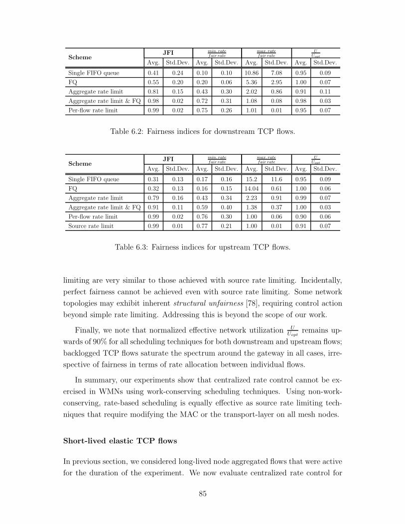
SchemeJFI min. rate
fair ratemax. ratefair rate
UUopt
Avg. Std.Dev. Avg. Std.Dev. Avg. Std.Dev. Avg. Std.Dev.
Single FIFO queue 0.41 0.24 0.10 0.10 10.86 7.08 0.95 0.09
FQ 0.55 0.20 0.20 0.06 5.36 2.95 1.00 0.07
Aggregate rate limit 0.81 0.15 0.43 0.30 2.02 0.86 0.91 0.11
Aggregate rate limit & FQ 0.98 0.02 0.72 0.31 1.08 0.08 0.98 0.03
Per-flow rate limit 0.99 0.02 0.75 0.26 1.01 0.01 0.95 0.07
Table 6.2: Fairness indices for downstream TCP flows.
SchemeJFI min. rate
fair ratemax. ratefair rate
UUopt
Avg. Std.Dev. Avg. Std.Dev. Avg. Std.Dev. Avg. Std.Dev.
Single FIFO queue 0.31 0.13 0.17 0.16 15.2 11.6 0.95 0.09
FQ 0.32 0.13 0.16 0.15 14.04 0.61 1.00 0.06
Aggregate rate limit 0.79 0.16 0.43 0.34 2.23 0.91 0.99 0.07
Aggregate rate limit & FQ 0.91 0.11 0.59 0.40 1.38 0.37 1.00 0.03
Per-flow rate limit 0.99 0.02 0.76 0.30 1.00 0.06 0.90 0.06
Source rate limit 0.99 0.01 0.77 0.21 1.00 0.01 0.91 0.07
Table 6.3: Fairness indices for upstream TCP flows.
limiting are very similar to those achieved with source rate limiting. Incidentally,
perfect fairness cannot be achieved even with source rate limiting. Some network
topologies may exhibit inherent structural unfairness [78], requiring control action
beyond simple rate limiting. Addressing this is beyond the scope of our work.
Finally, we note that normalized effective network utilization UUopt
remains up-
wards of 90% for all scheduling techniques for both downstream and upstream flows;
backlogged TCP flows saturate the spectrum around the gateway in all cases, irre-
spective of fairness in terms of rate allocation between individual flows.
In summary, our experiments show that centralized rate control cannot be ex-
ercised in WMNs using work-conserving scheduling techniques. Using non-work-
conserving, rate-based scheduling is equally effective as source rate limiting tech-
niques that require modifying the MAC or the transport-layer on all mesh nodes.
Short-lived elastic TCP flows
In previous section, we considered long-lived node aggregated flows that were active
for the duration of the experiment. We now evaluate centralized rate control for
85

short-lived adaptive flows that are active only for part of the experiment. When
these flows terminate, an efficient rate allocation mechanism must allow for dis-
tributing the freed resources to other flows in the network. Similarly, when a new
flow is born, it should be possible to expeditiously allocate it its share of the network
resources.
Flow activation/termination can be detected in multiple ways. TCP stream
activation and tear-down can be detected by the exchange of the TCP-specific
three-way handshake messages. In our case where a flow bundle constitutes mul-
tiple TCP streams, we simply use the presence or absence of packets to determine
the current state of stream activity, thus obviating any overhead associated with
the distribution of stream activity information. On detecting a new stream, the
centralized controller simply computes a new rate per active stream and starts en-
forcing it. Detecting stream deactivation can be a little tricky, and the controller
has to wait some time interval during which no packet is received from a flow. This
time interval should be a function of the average delay experienced by the packets
from a flow as well as the jitter.
We consider the results of a 7-hop chain (see Figure 3.1) with nodes indexed
0, 1, 2, ...7, with node 0 being the gateway router. Five flows are active between the
time interval 100–150 s. At 150 s., flows 1→0 and 0→5 are terminated. At time 200
s., flow 0→7 is turned off. Finally, at time 250 s, flows 1→0 and 0→7 are turned
back on. Flow throughput values are shown in Figure 6.5. Here we show our results
with per-flow rate limiting at the gateway. We are particularly interested in the
convergence times required for the flows to converge around their new fair rates.
We note that this convergence time is a function of the TCP state. A TCP agent
starts up in slow start, where its congestion window builds up exponentially over
time. This allows flows 1→0 and 0→7 to rapidly approach their fair rate within
the 5 s. resolution of the graphs. However, increasing rates for flows in congestion
avoidance modes is slower where the congestion window can only increase linearly
with time. Because of this, the flows 3→0 and 0→6 take up to 15 s. to approximate
their new fair rate at 215 s.
Non-adaptive Flows
Router-assisted rate control mechanisms are targeted at adaptive transport proto-
cols that can react to congestion notification. TCP is the canonical example of such
an adaptive protocol and constitutes the bulk of Internet traffic [121]. However,
many delay-sensitive applications such as streaming media and telephony that pre-
86

0
20000
40000
60000
80000
100000
120000
100 150 200 250 300
Thr
ough
put (
bps)
Time (sec)
Flow goodput over time
Flow 1->0Flow 3->0Flow 0->5Flow 0->6Flow 0->7
Figure 6.5: Throughput vs. time for a 7-hop chain with per-flow rate limiting at
the gateway. Flows 1→0 and 0→5 terminate at 150 s., while flow 0→7 terminates
at 200 s. Flows 1→0 and 0→7 are reactivated at 250 s.
fer timeliness to reliability use a UDP-based transport. In this section, we evaluate
the performance of centralized rate control for such non-adaptive flows.
We simulate a 3-hop chain topology, with nodes indexed 0, 1, 2, 3 and node 0
set as the gateway (see Figure 3.1). Our UDP constant bit rate (CBR) applica-
tion generates a 500-byte payload at 5 ms. intervals, for a total load of 800 Kb/s.
We considered both upstream and downstream flows, with a UDP stream origi-
nating/terminating per mesh node respectively. With 1 Mb/s wireless links, the
max-min fair rate is approximately 124 Kb/s. Thus our UDP sources generate
traffic load that is higher than the fair share per-flow, but is still low enough to
prevent complete channel capture by any single flow. Our results with per-flow rate
limiting at the gateway are shown in Table 6.4.
We observe that gateway-assisted rate control in WMNs can only successfully
contain downstream flows. In this case, it effectively acts as source rate control,
limiting each stream to its fair share on the wireless network. However, upstream
flows continue experiencing unfairness; while we can limit the goodput of flow 1 to
its fair share by dropping its excess traffic at the gateway, its non-adaptive transport
protocol still sources traffic at 800 Kb/s across the wireless channel, thus keeping
the medium busy and starving out other flows.
We note that while gateway-assisted rate control cannot provide protection
87

Traffic Type Flow avg.rate
fair.rateJFI
Upstream UDP
1→0 1.00
0.542→0 0.31
3→0 0.02
Downstream UDP
0→1 1.00
1.000→2 1.00
0→3 1.01
Table 6.4: Per-flow centralized rate control for upstream and downstream UDP
flows in a 3-hop chain with gateway node 0.
40000
42000
44000
46000
48000
50000
52000
54000
0 10 20 30 40 50
Ave
rage
Ban
dwid
th (
kbps
)
FIFO Size (packets)
Average Bandwidth vs. FIFO Size
IFQ = 5IFQ = 10IFQ = 20IFQ = 50
(a) Bandwidth vs. FIFO size
0
0.5
1
1.5
2
2.5
3
3.5
0 10 20 30 40 50
Ave
rage
Del
ay (
seco
nds)
FIFO Size (packets)
Average Delay vs. FIFO Size
IFQ = 5IFQ = 10IFQ = 20IFQ = 50
(b) Delay vs. FIFO size
Figure 6.6: Impact of per-flow queue size at the gateway as a function of the wireless
interface FIFO queue (IFQ) size at mesh nodes. The range information corresponds
to the IFQ size of 20 packets at all mesh nodes.
against channel capture by greedy upstream UDP flows, the fact that flow 1 sees
a loss rate of around 70% means that there is little useful traffic being carried for
this flow. If this flow was a multimedia application, this high loss rate will result
in unacceptable performance, leading to a user-triggered backoff [14]: i.e., the user
will either adjust the application to use a less bandwidth-intensive coding technique
(e.g., reduced video resolution), or will simply terminate the application. Either
action indirectly improves the fairness for remaining flows.
Impact of FIFO Buffer Size
We experimented with a 5-hop chain to understand the impact of the size of per-flow
queue at the gateway on flow bandwidth and delay. We varied this per-flow queue
88

size from 5 to 50 packets, while adjusting the mesh nodes’ wireless interface queue
(IFQ) size from 5 to 50 packets. Our results are shown in Figure 6.6, with range
information shown for the case of an IFQ of 20. We found that the gateway per-
flow queue size of 5 packets yielded minimum delay, with little effect on bandwidth
provided the IFQ was 10 or larger. A smaller IFQ of 5 packets results in considerable
drop of throughput from buffer overflows at nodes that relay traffic for multiple
other nodes in the network.
6.4 Testbed Analysis
In addition to our simulation results described previously, we have also evaluated
the performance of gateway-assisted rate control on a multihop wireless testbed.
In this section we first describe our testbed implementation and then illustrate the
efficacy of gateway control through experimental analysis.
6.4.1 Testbed Implementation
We set up a 9-node WMN testbed on the 4th floor of the E&IT building on the
University of Waterloo campus. Node placement is shown in Figure 6.7a. We
identify the nodes by alphabets A through I.
Our node configuration is shown in Table 6.5. Each node is retrofitted with two
wireless interfaces. We use one interface for the multihop wireless backhaul, and
the other interface for the access network. The two interfaces are configured to use
orthogonal (non-overlapping) channels. Node E has additional wired connectivity
and serves as the gateway mesh router for our testbed.
Software configuration
In addition to the base operating system and relevant drivers, we use the following
software in our testbed implementation.
Linux traffic control (tc) Linux traffic control (tc) is a utility for configuring
the traffic management functionality in the Linux kernel. tc is distributed as a part
of the iproute2 package. Here we introduce the three architectural components
of this framework used in our implementation: queueing discipline (qdisc), classes,
and filters. We refer the reader to the relevant documentation [46] for other details.
89

(a) Testbed node placement
(b) Testbed routing topology
Figure 6.7: A 9-node multihop wireless testbed on the 4th floor of the E&IT building
on University of Waterloo campus. Node locations are identified by alphabets A
through I. We use ETX routing metric with OLSR on the wireless network. Node
E serves as the gateway node and bridges traffic between the wired and the wireless
networks through its 1 GigE interface.
90

Node specifications 1.2 GHz VIA C7 fanless processor, 1 GB RAM, 40 GB HDD
Wireless interface Two EMP-8602 PLUS-S 802.11a/b/g radios (Atheros 5006
chipset) per node
Antennas Tri-band rubber duck antennas. 5 dBi gain in 5 GHz band
PHY link 802.11a with link rates up to 54 Mb/s
Radio channel Channel 48 (5.24 GHz) for multihop backhaul. Channel 52
(5.26 GHz) for access network. Both channels are unused by
the production network
Operating system Arch Linux distribution (kernel 2.6.28) patched for Web100
Wireless drivers Open source MadWifi v0.9.4.1
Routing olsr.org v0.5.6-r3 with ETX metric
Table 6.5: Attribute summary of testbed configuration
A qdisc is a scheduler that manges the queue associated with a device. Most
devices have one or more qdiscs (one exception is the loopback device that does
not have any qdiscs). The root qdisc is directly attached to the network device.
In Linux, the root qdisc is, by default, a FIFO queue. This is an example of a
classless qdisc, i.e., the qdisc does not internally subdivide or discriminate between
packets. Classful qdiscs, on the other hand, may contain multiple classes, each
corresponding to a traffic type. Each class has its own qdisc, which may also be
classful, thus creating a tree-like hierarchy of classes. Filters may be used to classify
traffic into classes; a filter is a set of rules corresponding to the conditions for packet
classification. Note that the network device communicates only with the root qdisc
to enqueue or dequeue a packet. This root qdisc is then responsible for invoking
the correct operation on the relevant classes.
The qdiscs we use in our implementation are FIFO (called pfifo-fast in Linux
terminology), Token Bucket Filters (TBF), Stochastic Fair Queueing (SFQ), and
Hierarchical Token Bucket (HTB). FIFO and TBF are classless, while HTB is a
classful qdisc. SFQ is also considered a classless qdisc [46] since its internal clas-
sification mechanism cannot be configured by the user. The TBF qdisc is a rate
limiter that passes the packets at a rate that is smaller of the packet arrival rate
or the administratively set rate for this qdisc. SFQ is a simple implementation of
the fair queueing algorithms. It identifies a flow using source and destination IP
addresses and ports. HTB is a classful TBF that uses a combination of filters for
classification and TBF for rate enforcement.
91

Routing protocol We use the olsr.org [3] implementation of the popular Opti-
mized Link State Routing (OLSR) [24] protocol. OLSR is a proactive link state
routing protocol: each mesh node maintains a table of routes to all other nodes
it has discovered via periodic exchange of control messages. OLSR uses two types
of control messages: HELLO messages between one-hop neighbors are used for lo-
cal discovery, while Topology Control (TC) messages are used to diffuse link-state
information throughout the network. Optimizations introduced in OLSR use a
controlled flooding mechanism in which only select nodes called multipoint relays
(MPRs) broadcast this link-state information.
We use OLSR with Expected Transmission Count (ETX) [27] routing metric.
ETX is an estimate of the number of transmissions required to send a unicast packet
over a wireless link. It is calculated by broadcasting a predetermined number of
short probe packets and counting the number of packets successfully received over
a wireless link. This is used to determine forward and reverse packet delivery ratios
(df and dr, respectively) for the link. The ETX value for this link is then calculated
as follows:
ETX =1
df × dr
The routing protocol then selects a path with the smallest sum of ETX values along
the constituent links.
The routing protocol sets up our 9-node testbed in a multihop configuration
shown in Figure 6.7b. The routing tree is rooted at the gateway node E which
bridges traffic between the wired and the wireless networks through its 1 GigE
interface.
Web100 We use the Web100 suite of software [4] to access the TCP statistics on
a mesh node. Web100 consists of a kernel patch that collects and exposes these
statistics through a set of instruments known as Kernel Instrument Set (KIS)[85],
as well as a library that defines an API for reading these statistics. Under Linux,
these statistics are accessible through the /proc file system.
iperf We use iperf [1] to perform network traffic measurements in our testbed.
iperf operates in a client/server mode where a client transmits a test stream to a
server. We typically run each experiment for a duration of 100 s. to capture the
stable, long-term behavior of a TCP stream.
92

0
500
1000
1500
2000
2500
3000
3500
A B C D F G H I
Thr
ough
put (
Kb/
s)
Mesh node
TCP downloads using FIFO queues without any rate limiting
Downloads (E to other nodes)
(a) Download flows
0
1000
2000
3000
4000
5000
6000
7000
A B C D F G H I
Thr
ough
put (
Kb/
s)
Mesh node
TCP uploads using FIFO queues without any rate limiting
Uploads (other nodes to E)
(b) Upload flows
Figure 6.8: Flow rates distribution with FIFO queues for downstream and upstream
flows in our WMN testbed. Error bars are the 95% confidence intervals.
6.4.2 Evaluation
We evaluate the performance of both upstream and downstream TCP flows between
the mesh routers and the wired server. The gateway node E bridges traffic between
the wireless and the wired networks through its 1 GigE interface. Thus the traffic
flows in our testbed are bottlenecked by the shared wireless spectrum.
FIFO Queues with no Rate Limiting
We first present our results using a shared FIFO queue at the gateway. These
results are summarized for both download and upload flows in Figure 6.8. Error
bars are the 95% confidence intervals.
Generally, one-hop flows have a higher throughput compared to flows traversing
two or more hops which exhibit unfairness, including starvation. For gateway-in-
the-middle chain, we find that the available capacity is unfairly shared between
the two one-hop nodes, B and D. This is partly due to the fact that node D re-
lays traffic for twice as many nodes compared to node B (Nodes B and D obtain
equal throughput for both upstream and downstream flows if they are the only
flows transmitting to the gateway C). JFI is better for gateway-in-the-middle chain
compared with gateway-in-the corner: 0.46 vs. 0.27 for download flows, and 0.61
vs. 0.28 for upload flows, respectively. We note that a distribution in which the
network capacity is assigned to a single flow with all others starving yields a JFI
of 0.2 in a network with 5 flows (see Section 2.1.5).
93

Efficacy of Gateway-enforced Control
We characterize the efficacy of gateway-enforced rate control through a series of
experiments similar to those used in Section 4.1.4, albeit this time using TCP with
gateway rate control. We gradually increase the rate allocated at the gateway
using one of the enforcement mechanisms in Figures 6.1b and 6.1c, and measure
the corresponding throughput of the TCP streams. We characterize the resulting
network response by plotting the allocated rate vs. the measured flow rate. Our
results are discussed below.
Figure 6.9 shows our results for both download and upload flows. The vertical
axis is the measured per-flow rate, while the horizontal axis is the rate allocation
at the gateway (per-flow or aggregate).
Our main observation is that initially all flow rates (both uploads and down-
loads) increase in parallel with increasing rate allocation at the gateway. Increasing
this allocation beyond the fair share point, however, produces increasing through-
put for smaller-hop flows at the expense of flows traversing a larger number of hops.
Thus, the gateway control mechanism can effectively enforce fairness in rate allo-
cation as long as the allocated rate at the gateway does not exceed the fair rate for
the network. This observation is consistent with the simulation results described
earlier in this chapter in which we used a computational model to determine the
fair share point for a given network topology.
We further note that the fair share point for download flows is approximately
twice that of upload flows for the same topology. We suspect that this is due to
asymmetric wireless links in our network. We characterized this asymmetry by
performing bulk TCP transfers between the gateway and individual mesh nodes
in isolation with other flows turned off. Our results are show in Figure 6.10. We
observe that a download flow from the gateway E to node C gets approximately
65% more throughput than an upload flow from C to the gateway E. Similarly, the
download flow from E to D gets about 18% more throughput that the upload from
D to E. We note that since the wireless links exhibiting this asymmetry are also
the transit link for traffic between nodes A and B and the gateway., it considerably
improves the total network capacity with download flows.
94

0
100
200
300
400
500
600
700
800
0 500 1000 1500 2000 2500 3000 3500 4000 4500
Mea
sure
d ra
te (
Kb/
s)
Aggregate rate limit (Kb/s)
Measured flow goodput vs. GW enforced aggregate rate limit with FQ
E->AE->BE->CE->DE->FE->GE->HE->I
(a) Downloads. Gateway aggregate rate limit
0
100
200
300
400
500
600
700
800
0 100 200 300 400 500
Mea
sure
d ra
te (
Kb/
s)
Per-flow rate limit (Kb/s)
Measured flow goodput vs. GW enforced per-flow rate limit
E->AE->BE->CE->DE->FE->GE->HE->I
(b) Downloads. Gateway per-flow rate limit
0
50
100
150
200
250
300
350
400
450
500
0 500 1000 1500 2000
Mea
sure
d flo
w r
ate
(Kb/
s)
Aggregate rate limit (Kb/s)
Measured flow goodput vs. GW enforced aggregate rate limit with FQ
A->EB->EC->ED->EF->EG->EH->EI->E
(c) Uploads. Gateway aggregate rate limit
0
100
200
300
400
500
0 50 100 150 200 250 300 350
Mea
sure
d ra
te (
Kb/
s)
Per-flow rate limit (Kb/s)
Measured flow goodput vs. GW enforced per-flow rate limit
A->EB->EC->ED->EF->EG->EH->EI->E
(d) Uploads. Gateway per-flow rate limit
Figure 6.9: Measured flow goodput as a function of the gateway rate limit for the
testbed nodes
95

0
5
10
15
20
25
A B C D F G H I
Flo
w r
ate
(Mb/
s)
Mesh node
TCP throughput asymmetry
Downloads (E to other nodes)Uploads (Other nodes to E)
Figure 6.10: Asymmetric wireless links in our testbed. We show the average down-
load and upload throughput between the mesh node and the gateway. Nodes C
and D shows maximum asymmetry between download and upload flows.
6.5 Summary
In this chapter we explored the feasibility of using centralized rate control that
can be enforced at traffic aggregation points such as gateway routers. We show
that router-assisted techniques in wired networks, including work-conserving packet
scheduling (such as FQ and its variants) and probabilistic packet-drop techniques
(such as AQM and its variants) are inadequate as centralized rate control techniques
in WMNs. This is because of fundamental differences in the abstraction of wired and
wireless networks: (1) transmissions on wired links can be scheduled independently,
and (2) packet losses in wired networks occur only as queue drops at bottleneck
routers. Our experiments indicate that non-work-conserving rate-based centralized
scheduling can be used effectively in WMNs. Even rate-limiting the aggregate traffic
passing through the gateway router improves the fairness index by a factor of 2
over the base case with a shared FIFO queue. Further granularity in rate allocation
control can be obtained by isolating flows using per-flow queueing and by exercising
per-flow rate limiting. The fairness indices achieved with these modifications are
comparable to source rate limiting techniques that require modifying the MAC or
the transport-layer on the end-hosts.
Having established the feasibility of gateway-assisted rate control in WMNs,
our next goal is to move away from the computational model used in this chap-
96

ter for determining rate information. We are interested in developing heuristics
and mechanisms to estimate flow rates based strictly on the information available
locally at the gateway. The remaining chapters in this dissertation describe our
measurement-based approach in which the rate controller adapts its behavior in
response to changing network and flow conditions.
97

Chapter 7
Aggregate Rate Controller
Having established the efficacy of gateway nodes in enforcing rate control for adap-
tive traffic flows, we now turn our attention towards designing practical centralized
rate controllers, i.e., we wish to move away from the computational model based
approaches, and instead develop a framework of heuristics that are practically fea-
sible for deployment by an ISP operating a WMN. In this chapter we propose
Aggregate Rate Controller (ARC), that can enforce approximate max-min rate al-
location using only the information locally available at the gateway. ARC manages
the net amount of traffic allowed through the network, relying on the underlying
max-min fairness characteristics of DCF to apportion this capacity fairly amongst
all contending flows. This chapter discusses the implications of max-min fairness
in WMNs, the design considerations governing our proposed controller, as well as
its performance evaluation using simulations and testbed analysis.
7.1 Introduction
In Chapter 6, we proposed and verified the efficacy of using traffic-aggregation
points like gateway nodes in enforcing rate control for adaptive traffic flows. The
computational model that we used required both the network topology and link
interference information to compute the fair rate vector. In general, gathering this
information requires distributed coordination amongst the nodes. In this chap-
ter we remove these requirements and propose a framework of gateway-enforced
heuristics that can enforce approximate max-min rate allocation only using the
local information available at the gateway.
Our proposed controller exploits the underlying max-min fairness characteristics
98

of 802.11 MAC. Using simulations, we establish that the rate allocation vector in
a WMN is a function of the aggregate capacity of that network. We define this
aggregate capacity as the sum of end-to-end rate of all active flows. Similarly,
the fair-aggregate capacity is the sum of end-to-end max-min rates of all active
flows. We show that when the aggregate capacity of a network is limited to its
fair-aggregate capacity, the 802.11 MAC apportions this allocated capacity in an
approximate max-min manner across all flows. This aggregate capacity does not
need to be managed by a large set of distributed source rate limiters; instead, it
can simply be managed by a single rate limiter at the gateway node.
This forms the basis of our Aggregate Rate Controller (ARC), named because
it allocates rate to data traffic as an aggregate bulk, relying on the underlying
MAC to distribute it fairly across contending flows. We propose heuristics that
allow ARC to search for fair-aggregate capacity of the network amongst the set of
feasible allocations. Our measurement-based, closed-loop feedback-driven heuristic
uses existing data traffic as capacity probes, thus minimizing control overhead.
While ARC singularly improves fairness indices, we show that combining it with
FQ provides isolation between different flows, further improving fairness.
Our contributions in this chapter are as follows: First, we show that distributed
bottlenecks can exist even in a WMN where traffic patterns are skewed towards
the gateway. Max-min rate allocation allows us to saturate these bottlenecks and
efficiently utilize the available capacity. Second, we characterize the response of
TCP flows in a 802.11 multihop network as a function of the aggregate capac-
ity allowed through its traffic aggregation points. We show that it is possible to
achieve approximate max-min flow rates simply by regulating the net amount of
data traffic allowed through the gateway to its fair-aggregate capacity. Third,
based on this behavior, we propose ARC, an aggregate rate-based scheduler that
uses a measurement-based approach to determine this fair-aggregate capacity of a
network, leading to approximate max-min allocation across contending flows.
This remainder of this chapter is organized as follows. In Section 7.2, we il-
lustrate the differences between the bottlenecks in a wired and a wireless network
and describe the conditions necessary for generating max-min rate allocation vec-
tors with lexicographically different components. In Section 7.3, we describe the
network response as a function of the aggregate network capacity and the circum-
stances under which it leads to approximate max-min fairness. We then propose a
framework of heuristics for determining this fair-aggregate capacity. We evaluate
these heuristics using simulations in Section 7.6 and using our WMN testbed in
Section 7.7, respectively.
99

7.2 Understanding Max-Min Fairness
The classical max-min rate allocation described in Section 2.1.2 is a commonly
used fairness criterion in wired networks. Its implications, however, are not well
understood in the context of multihop networks with a shared wireless spectrum.
In particular, it is deemed unsuitable for multi-rate wireless networks [45, 96, 118].
802.11 MAC provides max-min throughput fairness to all single-hop flows that are
within carrier sense range. It has been shown that this behavior degenerates to
equal rate allocation determined by the flow getting the least rate. We contend
that this is simply the well-known efficiency versus fairness trade-off that is also
seen, albeit with less severity, in wired networks. Further, in multihop networks,
these slower links constrain only the set of flows in their neighborhood; in networks
where there is another set of flows that do not share this neighborhood, max-min
fairness with its Pareto optimality allows us to make efficient use of the available
capacity. In this section we show how such distributed bottlenecks can exist even
in a WMN where the dominant traffic pattern is directed either towards or away
from the gateway, i.e., unlike the common perception that gateway is the common
bottleneck, flows may actually be bounds by distributed bottlenecks in different
parts of the network [56].
7.2.1 Max-min Fairness in Wired Networks
We characterize max-min fairness using the notion of bottleneck links as described
in [11]. Interconnected links in a network may have heterogeneous capacities. The
utilization of a link is defined as the sum total of rates for all flows traversing it. A
link is saturated when its utilization equals its capacity. A saturated link becomes
a bottleneck for a flow if that flow has a maximal rate amongst all other flows using
this link. When all flows experience such a bottleneck, the resulting rate allocation
is max-min fair [11]. This forms the basis of the water-filling algorithm used for
determining max-min rates. It works as follows: starting from zero, all flow rates
are increased in unison till one or more links gets saturated. This link then becomes
a shared bottleneck for all flows traversing it. Each of these flows have the same
rate as all other flows sharing this link. These set of flows are all capped at this
rate; flow rates for remaining uncapped flows are then increased in parallel till some
other link gets saturated. The procedure is repeated until rates are assigned to all
flows.
Figure 7.1 shows four nodes connected via wired tandem links. Link capacities
100

Figure 7.1: With wired, tandem links (capacities as shown), the max-min rates are
(f1, f2, f3) = (R, R2, R
2).
are R and 2R, as shown. Each node sources a flow terminating at destination D.
Using the water-filling algorithm, link 2 ↔ 1 saturates when a rate of R2
is allocated
to all three flows. At this point, link 2 ↔ 1 becomes the shared bottleneck for flows
f2 and f3. However, the rate of flow f1 can be further raised to R before it saturates
the link 1 ↔ D. Thus the max-min rate vector is (f1, f2, f3) = (R, R2, R
2).
7.2.2 Max-min Fairness in Wireless Networks
Directly extending this notion of max-min fairness to wireless networks is a chal-
lenge because resource allocation constraints are fundamentally different in a shared
wireless environment. A wired link has fixed, known capacity and can be scheduled
independently of other links. A wireless link, on the other hand, is an abstraction
for a shared spectrum between communicating entities and their neighbors, only
one of which can successfully transmit at a time. The capacity of a wireless link
is thus determined by the channel contention in this neighborhood, which in turn,
is spatially dependent on the node distribution around the sender or receiver. We
use the collision-domain model (Section 4.1.2) to capture this contention.
The utilization of a collision domain is the sum total of transmission times for
all links in a collision domain. The feasibility constraints on scheduling require that
this utilization cannot exceed 1. Mathematically, we represent it as follows: Let
R(m,n) be the link rate between neighboring nodes (m,n) in the network and let
r(m,n) be the traffic carried by this link. Let ri be the end-to-end rate for flow fi.
Then r(m,n) =∑
i:fi traverses (m,n)
ri. Let C = {C1, C2, ..., Cj} be the set of j collision
domains in this network. Ignoring physical and MAC layer headers, the feasibility
constraints require
∑
∀ (m,n) in Cp
r(m,n)
R(m,n)≤ 1, ∀p ∈ {1, 2, ..., j}
101

A saturated collision domain is defined as a collision domain which is fully uti-
lized. A saturated collision domain becomes a bottleneck for a flow if that flow has a
maximal rate amongst all other flows using this collision domain. A multihop flow
may be part of one or more collision domains; its end-to-end rate is then bound by
the collision domain that assigns it the lowest rate.
Using these definitions we adapt the iterative water-filling algorithm as for wire-
less environments as follows: starting from zero, we increase the rate of all flows in
parallel till a collision domain gets saturated. We then cap the rates for all flows
that traverse this collision domain. We update the residual capacity of remaining
collision domains based on rates already assigned to these saturated flows, and then
continue increasing the rates of remaining uncapped flows till another collision do-
main gets saturated. The process is repeated until a rate has been assigned to all
flows.
7.2.3 Max-min Fairness in WMNs
WMNs used for Internet backhauls have a dominant traffic pattern in which flows
are directed either towards or away from the gateway. This increases the spectrum
utilization around the gateway, eventually becoming a bottleneck for flows that are
not already bottlenecked elsewhere in the network. We know that the max-min
algorithm described above assigns equal rate to all flows sharing a common bottle-
neck. Thus when the spectrum around the gateway constitutes the single bottleneck
shared between all flows, max-min fairness results in equal rate allocations.
Despite this skewed traffic pattern in a WMN, topological dependencies can
create bottleneck collision domains other than those including the links around
the gateway. We show how multi-rate links and node distributions create such
distributed bottlenecks.
Multi-rate Links Figure 7.2 shows two variations of a simple chain topology
with two backlogged flows f1 and f2 transmitting through a common gateway GW .
The link rates are a mix of R and 2R, as shown. An equivalent wired network
would yield a rate vector of (f1, f2) = (2R,R) in both of these topologies. With
wireless links, however, the rate vector depends on the position of the slower link.
• Link f is the slower link in Figure 7.2a. Here f1 and f2 are bottlenecked by
the collision domain of links c and d, respectively. The slower link is a part of
102

(a) (f1, f2) = (2R
3, R
3)
(b) (f1, f2) = (R
3, R
3)
Figure 7.2: Max-min rate depends on the location of the slower link with capacity
R. If this slower link is one of links a, b, c, d, or e, the max-min fair rate vector
is (R3, R
3). If the slower link is at position f , the max-min rate vector is (f1, f2)
= (2R3, R
3). An equivalent wired network would always produce an allocation of
(R, 2R), with the lower rate for the flow traversing the slower link.
d’s collision domain. The max-min rate allocation for this scenario is (f1, f2) =
(2R3, R
3).
• If the slower link is one of the links b, c, d, or e, the max-min rate allocation is
(f1, f2) = (R3, R
3). The collision domains of links c and d are fully saturated at
this rate and form the bottleneck for flows f1 and f2 respectively.
• If the slower link is a, the max-min allocation is still (f1, f2) = (R3, R
3). However,
in this case the two flows are both bottlenecked by a common collision domain
of link c.
Node Distribution Multi-rate links are not necessary to create distributed bot-
tlenecks; these may even exist in a network with uniform rate wireless links. Fig-
ure 7.3 shows three flows f1, f2, and f3 transmitting to a common gateway node
over wireless links with uniform capacity R. f2 and f3 are bottlenecked by the
collision domain for link d, and hence share equal rates. f1 is bottlenecked by col-
lision domain of link c. The max-min fair share in this topology is (f1, f2, f3) =
(R5, R
10, R
10).
103

Figure 7.3: Max-min fair rates because of bottlenecks associated with node density
(f1, f2, f3) = (R5, R
10, R
10)
7.3 Network Response to Aggregate Rate Con-
trol
In this section, we analyze the flow goodput response as a function of the aggregate
network capacity, i.e., if the network is allowed to transport an aggregate of x units
of traffic, how does the 802.11 MAC distribute these x units of capacity between
multihop TCP flows all contending for channel access? In this work we experiment
with managing this aggregate capacity via a single token bucket at the gateway
router.
We experiment with the two rate limiting mechanisms in Figure 7.4. The dif-
ferences between the two architectures were described in Section 6.2.3. To recap,
in Figure 7.4a, all received data is stored in a shared buffer till there are enough
tokens to send it out. This simple architecture has known performance problems:
it does not provide any isolation between flows and a shared FIFO queue can cause
synchronization between TCP connections carrying bursty traffic. We address these
issues by using per-node queueing at the gateway as shown in Figure 7.4b. This
allows us to separate data from different subscribers irrespective of the number of
TCP micro-flows a subscriber generates.
Using ns-2 [2], we simulate a number of network topologies with gateway rate
limiting the aggregate TCP traffic it bridges between the wired and the wireless
network. Figure 7.5 shows the measured flow goodput as a function of the aggregate
capacity for the network in Figure 7.3 with 1 Mb/s 802.11 links. Each data point
for a given rate limit represents the average of 5 experimental runs. Recall that the
optimal max-min fair rate computed for this topology is (f1, f2, f3) = (R5, R
10, R
10).
The nominal capacity of a 1 Mb/s 802.11 link is approximately 800 Kb/s, assuming
a perfect channel and no collisions. This translates to (f1, f2, f3) = (160 Kb/s, 80
Kb/s, 80 Kb/s) and a fair-aggregate capacity of 320 Kb/s.
104

(a) Aggregate rate limit with a shared queue
(b) Aggregate rate limit with a per-node queue
Figure 7.4: The main architectural components of ARC
We make the following observations from Figure 7.5. First, both plots show an
initial increase in rate of all flows with increasing rate limit. These rate increases are
prolonged (up to an aggregate rate limit of 225 Kb/s) and more uniform (all rates
within 2% of each other up to this rate limit) in Figure 7.5b where we use a per-
destination node queue at the gateway. In contrast, Figure 7.5a shows a deviation of
up to about 50% between the maximum and the minimum rate flows between 0−150
Kb/s rate limit. This deviation increases with increasing aggregate rate limit.
Thus separating flows while rate limiting at the gateway shows improved fairness
characteristics. Second, increasing the rate limit beyond 225 Kb/s in Figure 7.5b
only increases the rate of flow f1 while the rate of flows f2 and f3 taper off. Between
105

0
100000
200000
300000
400000
500000
600000
0 100 200 300 400 500 600 700 800
Mea
sure
d ra
te (
b/s)
GW Aggregate Rate Limit (kb/s)
Flow goodput vs. GW rate limit
Flow GW->1Flow GW->6Flow GW->7
(a) Shared queue with GW rate limiting
0
100000
200000
300000
400000
500000
600000
0 100 200 300 400 500 600 700 800
Mea
sure
d ra
te (
b/s)
GW Aggregate Rate Limit (kb/s)
Flow goodput vs. GW rate limit
Flow GW->1Flow GW->6Flow GW->7
(b) Per-destination queue with GW rate limiting
50000
100000
150000
200000
250000
300000
350000
400000
450000
500000
550000
600000
167 167 167 167 167 167 167 167 167 167 167
Thr
ough
put (
b/s)
Destination Nodes
Average goodput with FQ at GW
Shared FIFO
Queue = 5
Queue = 10
Queue = 15
Queue = 20
Queue = 25
Queue = 30
Queue = 35
Queue = 40
Queue = 45
Queue = 50
(c) FIFO vs. FQ at the GW
Figure 7.5: Flow goodput vs. gateway aggregate rate limit for the network topology
in Figure 7.3 with 1 Mb/s 802.11 links. Figs. 7.5a and 7.5b use the enforcement
mechanism in Figs. 7.4a and 7.4b respectively at the gateway router. Figure 7.5c
shows average goodput for the same network with FQ at the gateway without any
rate limiting.
106

a rate limit of 250−350 Kb/s, for example, f1 approximately doubles its rate while
registering a drop of only 4% in the average rate of f2 and f3. This drop in rate
increases with increasing aggregate capacity, e.g., at 400 Kb/s, the drop in average
goodput of f2 and f3 is approximately 7% compared to the highs seen at a rate
limit of 250 Kb/s. Third, at the computed fair-aggregate capacity of 320 Kb/s, the
measured rates of flows f1, f2, and f3 are all within 10% of their optimal max-min
rates computed assuming no collisions.
Similar to fair-aggregate capacity which is the sum of optimal max-min rates,
we define measured fair-aggregate capacity as the sum of measured individual flow
rates where the lexicographically lowest rate in the rate vector is no less than θ
times the maximum rate previously recorded for that flow. The intuition behind
the θ cutoff benchmark is that we are willing to tolerate a marginal decrease of
1− θ% times the maximum possible rate of the slowest flow as long as it results in
an increase in total network capacity. In this experiment, setting θ to 95% sets our
measured fair-aggregate capacity to 350 Kb/s. This is within 8% of the optimal
fair-aggregate capacity computed using the iterative max-min fair rate algorithm.
The role of per-node queueing at the gateway is important, though it alone is
insufficient to enforce flow rate fairness. In Figure 7.5c, we show rate allocations
achieved by varying the size of this per-node buffer. For comparison, we also show
our results with a shared FIFO queue of 50 packets. The error bars are the 95%
confidence intervals. In all cases f1 achieves a goodput in excess of 425 Kb/s, at
the cost of reduced goodput for distant flows.
We have validated this behavior for both upstream and downstream flows on a
number of topologies. The network in Figure 7.6a yields an optimal max-min rate
vector with three lexicographically different components. Its response characteris-
tics with upstream flows in Figure 7.6c are consistent with those seen in Figure 7.5b
with downstream flows. Between a rate limit of 0−400 Kb/s, all flow rates increase
equally in parallel (within 10% of each other), irrespective of the hop count or the
degree of contention. With the rate limit between 400 − 600 Kb/s, only the rate
of flows f1, f2, and f3 increase while f4, f5, f6, and f7 taper off; f1 registers an ap-
proximate increase of 200%, f2 and f3 about 80%, while there is a decrease of less
than 5% in average rate of flows f4, f5, f6, and f7. Increasing the aggregate capacity
beyond 600 Kb/s increases the rate of flow f1 only with all other flows tapering
off initially and later registering a decrease in goodput as rate limits are increased
beyond 700 Kb/s. Using our θ = 95% cutoff benchmark, we find the measured
fair-aggregate capacity of 625 Kb/s. This is approximately within 20% of the fair-
aggregate capacity computed considering optimal scheduling across a 802.11 link.
107

Apart from the increased collisions due to a larger network, this reduced efficiency
is partly also due to the fact that measured TCP goodput across a 2 Mb/s 802.11
link is less than two-times the corresponding goodput across a 1 Mb/s link.
We conclude from these experiments that the network response is a function of
the aggregate traffic transported by the network. In earlier chapters we have shown
that flow rate fairness characteristics are maximized when individual flows are rate
limited to their fair share of the network capacity. We show, that by extension, these
fairness characteristics similarly improve when the aggregate traffic transported by
the network is limited to its measured fair-aggregate capacity. Up to this traffic
load, the underlying 802.11 MAC can provide max-min rate allocation amongst
the contending nodes. Unlike prior work that requires a distributed set of source
rate limiters, the aggregate capacity of a network can be managed simply by a
single, centralized rate-based scheduler for both upstream and downstream flows in
a WMN.
7.4 Aggregate Rate Controller
Our results from the previous section show that if we limit the aggregate capacity of
a WMN to its measured fair-aggregate capacity, the resulting rate allocation with
TCP flows is approximately max-min fair. We now propose heuristics that allow
the gateway node to determine this fair-aggregate capacity.
We imposed the following set of practical constraints on a feasible solution:
• The mechanisms are limited to using information available locally at the gate-
way. This includes information available at the driver level, e.g., which mesh
nodes are directly associated with the gateway as well as the data rate used
for communication with each of those nodes.
• Mesh nodes use the standard 802.11 radios for the multihop backhaul. Con-
trol messages beyond those required by the standard may not be correctly
interpreted by a node.
• Client devices use the standard TCP network stack.
Our proposed heuristic ARC uses a simple measurement-based adaptive rate
allocation approach. It measures the rate obtained by all flows over a fixed interval
called epoch. If all flow rates are equal, it assumes the network is underutilized and
108

(a) (f1, f2, f3, f4, f5, f6, f7) = (R
3, R
6, R
6, R
12, R
12, R
12, R
12)
0
100000
200000
300000
400000
500000
600000
0 100 200 300 400 500 600 700 800 900
Mea
sure
d ra
te (
bps)
GW Aggregate Rate Limit (Kb/s)
Flow goodput vs. GW rate limit
Flow 1->GWFlow 6->GWFlow 7->GW
Flow 12->GWFlow 13->GWFlow 14->GWFlow 15->GW
(b) Shared queue with GW rate limiting
0
100000
200000
300000
400000
500000
600000
0 100 200 300 400 500 600 700 800 900
Mea
sure
d ra
te (
b/s)
GW Aggregate Rate Limit (Kb/s)
Flow goodput vs. GW rate limit
Flow 1->GWFlow 6->GWFlow 7->GW
Flow 12->GWFlow 13->GWFlow 14->GWFlow 15->GW
(c) Per-source queue with GW rate limiting
Figure 7.6: A topology with 7 flows that yield 3 lexicographically different compo-
nents in the optimal max-min rate vector.
109

Figure 7.7: Rate evaluation and allocation work in a closed-loop feedback control.
increases the aggregate capacity allocated at the gateway. If the rates are unequal,
then the flows with lower rate are either bottlenecked locally or are experiencing
unfairness. We differentiate between the two by maintaining state on historic flow
rates. The aggregate capacity allocated at the gateway is decreased only when we
suspect unfairness. Our heuristic thus mimics the behavior of adaptive protocols
like TCP by probing the network for capacity information and adjusting its behavior
in response. This closed-loop feedback system allows ARC to adapt to changing
network and traffic conditions.
We now describe the ARC heuristic in detail. ARC is a system module on
the gateway mesh router. It sits between the MAC layer and the network layer,
operating transparently between them. Its three main components perform the
following functions:
1. Flow classification
2. Rate evaluation and allocation
3. Flow rate enforcement
7.4.1 Flow Classification
In this first step, ARC performs flow classification for all data traffic (ingress and
egress) through the gateway. Here flow refers to any suitable classification of traffic
and its precise definition is left as a policy decision for the network operator. In
this dissertation we have classified flows based on the source or destination mesh
router. Thus a flow fi represents the aggregate of all micro-flows originating from,
or destined to, node ni in the network. In this context, we use nodes and flows
interchangeably in our discussion. Our classification methodology requires a simple
lookup of the packet header given a known offset, and can be performed efficiently.
We note that such a classification is consistent with the common practices employed
110

by ISPs on wired access networks, where capacity is managed on a per-subscriber
basis.
7.4.2 Rate Evaluation and Allocation
Rate evaluation This component measures the flow rate of all flows in a given
epoch τt. These measured rates determine the aggregate capacity allocated at the
gateway for the next epoch τt+1. Let the duration of the epoch be δ. This value is
configurable, though for stability it should operate at different timescales than the
control action of TCP senders. For instance, δ can be set to multiples of round-
trip time so that TCP sources can react to changes in rate allocation and stabilize
around their new values.
After every epoch, the mechanism compares the measured rate ri for flow fi
with the rate rj obtained by some other active flow fj. Two possibilities exist:
1. If ri ≈ rj for ∀i, j ∈ N , the mechanism assumes the network capacity
is underutilized, i.e., the current estimate of aggregate network capacity
(Cmeas =∑N
i=1 ri) is low. It signals the rate allocation component to increase
the aggregate rate allocated to the network.
2. If ri < rj for any i, j ∈ N , the flow fi may be limited by its saturated local
bottleneck or it may be experiencing unfairness. We differentiate between
these cases by comparing ri to its previously recorded maximum value rimax.
If ri < rimax, then the flow is experiencing unfairness and we reduce the
aggregate rate limit at the gateway. On the other hand, if ri ≈ rimax, then fi
is bound by some local bottleneck. We increase the aggregate rate limit since
it may be usable by other flows that have not yet saturated their respective
bottlenecks.
The pseudo-code for this rate evaluation component is shown in Algorithm 1.
Rate Allocation The rate allocation component adjusts the token generation
rate B (see Figure 7.4) based on its estimate of the current network capacity.,
Cest. It adjusts this capacity estimate based on feedback from the rate evaluation
component. After every epoch, it adjusts Cest such that the new estimate Cest >
Cmeas when signaled to increase rates, or Cest < Cmeas otherwise. As described
earlier, Cmeas =∑N
i=1 ri. B is then set to Cest. This allocation is derived from the
111

Input: Epoch duration δ, inter-flow unfairness threshold γ, intra-flow rate
cutoff threshold θ, measured rate ri and historical rimax, ∀i ∈ N
Output: Rate increase or decrease decision
while once every δ time units do1
if ri
rj< γ and ri
rimax< θ for ∀i, j ∈ N then2
decAggRate;3
else4
rimax = ri ;5
incAggRate;6
end7
end8
Algorithm 1: Rate evaluation algorithm
network response in epoch τt and is enforced for the epoch τt+1 with the help of the
enforcement mechanism described in Section 7.4.3.
The rate allocation component may use any number of heuristics to determine
the new Cest. It has to search through the space of feasible allocations for the
new capacity estimates. A simple algorithm using exponential increase/decrease in
aggregate capacity is shown in Algorithm 2. In Section 7.5 we propose a heuristic
that uses binary search within upper and lower aggregate network capacity bounds
to allow for faster convergence to the fair rate values.
Input: Cmeas =∑N
i=1 ri
Output: New aggregate rate limit Cest.
incAggRate begin1
Cest = α× Cmeas; /* α > 1 */2
end3
decAggRate begin4
Cest = β × Cmeas; /* β < 1 */5
end6
Algorithm 2: Estimating network capacity using a simple exponential in-
crease/decrease algorithm
112

7.4.3 Flow Rate Enforcement
ARC uses a single token bucket at the gateway to control the aggregate network ca-
pacity. The token generation rate B is controlled by the rate allocation mechanism
above. Note that ARC can be used with either of the two enforcement mechanisms
in Figure 7.4. Our evaluation in this chapter uses ARC with FQ since it provides
better isolation between flows leading to improved fairness characteristics.
7.5 Design Considerations
7.5.1 Dynamic Flows
Our flow bundles are aggregates of micro-flows, and we expect them to be long-
lived for durations lasting tens of seconds. However, when they do terminate, any
unused capacity needs to be fairly allocated. Similarly, when a new flow emerges,
the rate allocation of existing flows will be adjusted. In particular, this impacts
rimax, the maximum achievable fair rate that we have observed for a flow. We
therefore modified Algorithm 1 to reset the rimax value on detecting a change in
the status of a stream.
We had described two flow activation/termination mechanisms in Section 6.3.3.
In our case where a flow bundle may contain multiple TCP streams, we simply
use the presence or absence of packets to determine the current state of stream
activity. In contrast to prior approaches [33], this reduces the complexity as well as
the state information maintained by the centralized controller. We evaluate ARC
with dynamic flows in Section 7.6.
7.5.2 Rate Increase/Decrease Heuristics
These heuristics help the rate allocation component explore the space of feasible
allocations in search of the fair-aggregate network capacity. We prefer heuristics
with quick convergence characteristics. Algorithm 2 outlined a simple heuristic
with exponential increase/decrease in capacity estimates. We now propose a bi-
nary search heuristic within pre-computed aggregate capacity bounds to provide
faster convergence. Binary search can converge Cest to approximate fair-aggregate
capacity in logarithmic time (approximately log2K steps, where K is the set of fea-
sible aggregate capacity values between the lower and the upper capacity bounds).
113

This heuristic works as follows: we first determine lower and upper bounds on feasi-
ble Cest (In Section 7.5.2 below, we provide an outline of how the initial upper and
lower bounds on Cest can be determined for WMNs with many-to-one traffic pat-
terns.) Then using binary search, we use the rate feedback in epoch τt to determine
Cest for epoch τt+1. The pseudo-code for this modified rate allocation component
is shown in Algorithm 3.
Input: Cmeas =∑N
i=1 ri and upper and lower aggregate capacity bounds Cup
and Clow respectively.
Output: New aggregate rate limit Cest.
incAggRate begin1
Clow = Cmeas;2
Cest = Cmeas+Cup
2;3
end4
decAggRate begin5
Cup = Cmeas;6
Cest = Clow+Cmeas
2;7
end8
Algorithm 3: Estimating network capacity using binary search within feasible
aggregate capacity bounds
Efficient and Fair Transport Capacity Bounds
The binary search heuristics described above search through the space of feasible
values for network capacity to determine the capacity for a given topology. In this
section we show how to determine the initial upper and lower capacity bounds to
jump-start the binary search heuristic. Note that the gateway is only aware of the
number of active flows at a given time and does not know the network topology.
Further, by symmetry, the capacity bounds computed for upload traffic (many-to-
one paradigm) also hold for download traffic (one-to-many).
Consider a network with N mesh routers exchanging data via the gateway.
We assume that each router has a single wireless interface connected to an omni-
directional antenna with unit gain. For simplicity, we assume that all nodes trans-
mit with a uniform power, obtaining a transmission range of d units. Let the inter-
ference range associated with a receiver be m units, where m ≥ d. Let k denote the
distance that allows concurrent transmissions along a path. For CSMA/CA radios,
k ≥ m.
114

Figure 7.8: Aggregate capacity is maximized when all flows consume minimal spec-
tral resource.
Optimal Upper Capacity Bound
With Perfect Scheduling The aggregate transport capacity is maximized when
the gateway is either receiving or transmitting data all the time. This happens
when all active nodes are one-hop away (i.e., within d units) from the gateway. If
the wireless links have a uniform capacity of W bits/s, the upper bound on the
aggregate send/receive capacity at the gateway is also W bits/s.
For multi-rate links, suppose that mesh router n1, n2, ..., nN connect to the gate-
way with link-rate vector W = {W1,W2, ...,WN}. Let T (i) be the fraction of time
required for a node ni to transmit or receive a packet of size si. If the underlying
MAC provides all nodes with equal transmit opportunities, then
T (i) =si
Wi∑
j∈N
sj
Wj
When all nodes exchange equal-sized packets, then the rate r(i) of node i is given
by
r(i) =1
∑
j∈N1
Wj
and the aggregate send/receive capacity at the gateway is
N∑
i=1
r(i) =N
∑
j∈N1
Wj
It is trivial to see that when Wi = Wj = W, ∀ i, j ∈ N , this expression reduces to
an aggregate capacity of W bits/s as described above.
115

Figure 7.9: Aggregate capacity is minimized when all flows consume maximal spec-
tral resource.
With 802.11 Scheduling: 802.11 lowers the capacity bound in two ways: MAC
overhead and packet loss. First, 802.11 MAC reduces capacity well below link rates
as it incurs a fixed overhead per packet due to backoff contention windows, link-
level ACKs for every successful data transmission, optional RTS/CTS exchange,
etc. Second, packets are susceptible to loss due to collisions from hidden terminals
or when multiple transmitters simultaneously countdown their backoff window to
zero.
The upper capacity bound we use in our simulations in Chapters 7 and 8 ac-
counts for MAC overhead (we assume 1500-byte Ethernet-friendly MTU), while
we ignore loss from collisions. This is a trade-off between accuracy and computa-
tional complexity. We accept reduced accuracy by using information that is readily
available at the gateway. The number of active mesh nodes N can be determined
through flow classification, while the link rate information used for each transmis-
sion is available at the radio interface driver.
Optimal Lower Capacity Bound
With Perfect Scheduling: The upper bound on aggregate capacity is obtained
when all active nodes consume minimal resource (e.g., spectrum) to communicate
with the gateway. Conversely, an efficient lower bound on aggregate capacity is
obtained when all active nodes consume maximal resource to reach the gateway.
A multihop flow consumes increasing spectral resource with each additional hop,
till the number of hops reaches k and the resulting spatial reuse allows transmissions
to be pipelined. At this point, the flow is consuming maximal spectral resource as
any additional hop will still allow for concurrent, pipelined transmissions. Thus the
lower bound of a network is a function of the spatial reuse allowed by the MAC.
A perfect scheduler allows for a fine-grained control of the spatial reuse. In
116

a chain of wireless nodes in Figure 7.9, transmissions from GW → 1 and 3 → 2
can occur in parallel while links 1 ↔ 2 and 3 ↔ 4 are kept idle. However, note
that transmissions GW → 1 and 2 → 3 cannot occur concurrently, and neither
can transmissions 3 → 2 and 1 → GW. Thus in a network with an equal mix
of upstream and downstream traffic, the lower bound on aggregate send/receive
capacity is W2
bits/s; with all unidirectional flows (upstream or downstream), the
aggregate send/receive capacity reduces to W3
bits/s.
With multi-rate links, the aggregate capacity is lowest when all active flows
traverse the slowest link. We assume that the link-rate vector W is lexicographically
ordered, i.e., Wi ≤Wi+1, ∀i ∈ N . Then the lower bound on the aggregate capacity
is W1
2for bidirectional and W1
3for unidirectional traffic.
With 802.11 Scheduling: The spatial reuse possible with perfect scheduling
and tight synchronization cannot be achieved with 802.11 scheduling. DCF’s bidi-
rectional handshake (DATA-ACK) requires the interfering nodes around both the
transmitter and the receiver to be disabled for the duration of the message ex-
change. In Figure 7.9 when there is an ongoing transmission from 1 → 2, links GW
↔ 1 and 2 ↔ 3 need to stay idle. This spatial reuse sets the optimal lower capacity
bound to W3
.
This spatial reuse can also be confirmed analytically. We use the physical model
of radio interference to identify the interfering nodes. In this model the packet
error rate (PER) at a receiver is a monotonically decreasing function of the Signal-
to-Interference-plus-Noise Ratio (SINR). In practice, we can define thresholds such
that probability of packet reception is approximately 1 when SINR exceeds a thresh-
old ψ.
SINR =PTX
dω
PN +∑
iPi
dωi
≥ ψ
where PN is the ambient noise, PTX and Pi are the transmit power of the transmitter
and interfering nodes respectively, d and di are the distance of the receiver from the
transmitter and interfering nodes, and ω is the path-loss exponent ranging from 2
(free-space path loss) to 4 (two-ray ground reflection path loss). Measurements have
indicated that the path loss exponent of 4 is more accurate [101] when d≫√hthr,
where ht and hr are the antenna height of the transmitter and receiver respectively.
Ignoring ambient noise PN and assuming all nodes transmit with equal power,
the interfering nodes that can transmit simultaneously without disrupting current
117

transmission are those at least di units apart, where
di ≥ 4
√
ψ ∗ d
Lee et al. [73] empirically show that SINR threshold ψ is around 10 dB to
achieve a Frame Reception Ratio (FRR) of 0.90. Substituting this value, we obtain
di ≥ 1.78 × d. This means 802.11 radios up to 2-hops away from the transmitter
or receiver may interfere with its reception. In Figure 7.9 when there is an ongoing
transmission from 3 → 4, links 1 ↔ 2, 2 ↔ 3, 4 ↔ 5, and 5 ↔ 6 are required to stay
idle. However, the transmission from GW ↔ 1 can proceed concurrently, giving
a spatial reuse of 13. This sets a lower bound of W
3on the theoretical aggregate
send/receive capacity of the gateway.
With multi-rate links, the aggregate capacity is lowest when all flows traverse
the slowest link. Consistent with our observations in Section 7.5.2, this bounds the
lowest aggregate capacity to W1
3, where W1 is the first element of the lexicographi-
cally ordered rate vector W.
Practically achievable bounds may be lower due to packet losses, non-optimal
carrier sense threshold, and other MAC-specific overheads.
7.6 Simulation Evaluation
We have implemented ARC in ns-2 [2]. Our module sits directly on top of the
wireless MAC layer, and can rate limit both upstream and downstream flows. A
gateway router with multiple wireless interfaces may use an ARC module per in-
terface to avoid synchronization between the flows on different interfaces. We rate
limit data packets only; system housekeeping messages such as routing updates
bypass ARC and are not rate limited.
We simulated ARC with the binary search heuristics from Section 7.5 (We
use the exponential rate increase/decrease heuristics for our testbed evaluation in
Section 7.7). Our various control parameters were as follows. The epoch duration δ
was set to 10 s.; choosing a value larger than the control action of TCP is important
for stability. Our inter-flow unfairness threshold was set to 0.9 and our intra-flow
rate cutoff threshold θ set to 0.95. We simulated elastic flows using an infinite file
transfer with TCP NewReno [34].
118

7.6.1 Long-lived Elastic TCP Flows
We compare the performance of ARC against the following:
1. A single, shared FIFO queue at the gateway.
2. An aggregate static rate limit (Static RL) that is the fair-aggregate capacity
of the network computed using the iterative max-min algorithm and applied
at the gateway using the enforcement architecture in Figure 7.4a.
3. Combining the Static RL with FQ at the gateway as shown in Figure 7.4b.
4. Dynamic ARC where the rate limit is recomputed every epoch using Algo-
rithm 1 and enforced by the mechanism shown in Figure 7.4b.
5. TCP Adaptive Pacing (TCP-AP) [33] rate-based scheduling mechanism that
requires modifications to all mesh routers (see Section 5.2 for details). We use
the ns-2 TCP-AP implementation of ElRakabawy et al. [32] and integrate it
in our simulation framework.
6. Source Rate Control (SRC) with the per-node rate pre-computed with the
iterative max-min algorithm and enforced via distributed source rate limiters.
It represents a performance upper-bound as individual max-min rates are
computed using an omniscient knowledge of network topology and enforced
at the source nodes without incurring any signaling overhead.
We first tested the topology in Figure 7.6a, substituting 1 Mb/s and 2 Mb/s
802.11 links for R and 2R, respectively. Our measured flow rates normalized to
their optimal max-min fair share are shown in Table 7.1. The actual measured
rates for the five mechanisms of our interest are shown in Figure 7.10. We see
roughly a two-fold improvement in JFI by simply introducing a static rate limit
compared to the shared FIFO queue. Combining this rate limit with FQ shows an
additional improvement. Ideally, Dynamic ARC would converge to the same results
as Static RL with FQ. Our results show that Dynamic ARC further improves the
fairness index, but at the cost of reducing the rate of the flows with the highest
throughput. This is partly because Dynamic ARC allocates the highest goodput
amongst all schemes for flows traversing the 1 Mb/s wireless links (An average
increase of 7%, 28%, 22%, and 11% against SRC, Static RL, Static RL+FQ, and
TCP-AP for flows 12, 13, 14, and 15.) This behavior of Dynamic ARC can be
adjusted using the control parameters γ and θ that trigger rate allocation decisions.
119

Scheme JFI f1 f2 f3 f4 f5 f6 f7
Shared FIFO 0.45 3.08 0.41 0.46 0.49 0.52 0.42 0.47
FQ 0.45 3.09 0.39 0.46 0.48 0.51 0.46 0.48
Static RL 0.84 1.67 0.67 0.67 0.67 0.66 0.64 0.67
Static RL+FQ 0.87 1.57 0.69 0.69 0.70 0.70 0.69 0.67
Dynamic ARC 0.97 0.55 0.61 0.61 0.85 0.86 0.85 0.84
TCP-AP 0.96 1.21 0.68 0.67 0.75 0.82 0.74 0.70
SRC 0.99 0.96 0.85 0.86 0.80 0.79 0.79 0.79
Table 7.1: Flow rate distribution Normalized flow rates for Figure 7.6a. TCP-AP
and SRC require changes on all mesh routers; all other scheduling techniques were
implemented at the gateway only
0
50000
100000
150000
200000
250000
300000
350000
400000
450000
500000
1 6 7 12 13 14 15 1 6 7 12 13 14 15 1 6 7 12 13 14 15 1 6 7 12 13 14 15 1 6 7 12 13 14 15
Thr
ough
put (
b/s)
Source Nodes
Average throughput
SRC StaticRL Static RL+FQ DynamicARC TCP-AP
Figure 7.10: Average throughput with 95% confidence intervals for the network in
Figure 7.6a.
120

SchemeJFI min. rate
fair ratemax. ratefair rate
UUopt
Avg. Std.Dev. Avg. Std.Dev. Avg. Std.Dev. Avg. Std.Dev.
Shared FIFO at GW 0.48 0.19 0.34 0.21 4.53 3.05 0.85 0.06
FQ at GW 0.51 0.16 0.36 0.20 3.34 1.36 0.86 0.05
Static RL at GW 0.94 0.03 0.61 0.17 1.26 0.41 0.81 0.10
Static RL & FQ at GW 0.94 0.04 0.60 0.20 1.14 0.14 0.83 0.08
Dynamic ARC 0.84 0.14 0.56 0.17 1.53 0.68 0.85 0.08
TCP-AP 0.82 0.14 0.53 0.25 1.33 0.17 0.87 0.04
Table 7.2: Comparative analysis of ARC fairness indices for downstream flows
Finally, we note that the JFI obtained with Dynamic ARC is within 2–3% of
that obtained with TCP-AP and SRC mechanisms. These distributed rate-based
scheduling mechanisms are challenging to deploy in WMNs built with commodity
mesh routers where the ISPs have limited control over the subscriber equipment.
We have extensively evaluated these set of mechanisms on a number of different
topologies, including chains (up to 10-hops) and grids (up to 6x6 node configura-
tions) with a random number of flows transmitting via a common gateway. Our
experiments included both upstream and downstream flows. For a given topology,
each experiment was repeated 25 times with different random seeds and random
flow activation sequences, and the results averaged. These results are summarized
in Table 7.2 for downstream and Table 7.3 for upstream flows. We omit SRC results
for downstream flows as that is equivalent to gateway rate control. On average,
Dynamic ARC shows a fairness improvement by a factor of 3 for upstream flows and
by a factor of 2 for downstream flows when compared to the base case with a shared
FIFO queue at the gateway with no rate limiting. In addition to these improved
fairness characteristics, Dynamic ARC achieves a normalized effective network uti-
lization of more than 80% for both downstream and upstream flows. These results
show close resemblance to TCP-AP and SRC mechanisms that require uniform en-
forcement of rate-based scheduling at individual mesh routers. SRC uses a static
rate limit for a given topology that was computed off-hand using the iterative max-
min fairness algorithm. In contrast, TCP-AP determines this rate dynamically, and
thus can react to changes in network and traffic conditions.
121

SchemeJFI min. rate
fair ratemax. ratefair rate
UUopt
Avg. Std.Dev. Avg. Std.Dev. Avg. Std.Dev. Avg. Std.Dev.
Shared FIFO at GW 0.31 0.13 0.12 0.43 4.34 1.34 0.74 0.11
FQ at GW 0.31 0.12 0.12 0.13 4.32 1.37 0.74 0.11
Static RL at GW 0.93 0.04 0.64 0.13 1.27 0.11 0.87 0.07
Static RL & FQ at GW 0.95 0.03 0.64 0.15 1.18 0.09 0.87 0.05
Dynamic ARC 0.94 0.05 0.60 0.19 1.12 0.25 0.81 0.08
TCP-AP 0.88 0.06 0.59 0.15 1.53 0.27 0.87 0.05
SRC 0.99 0.01 0.81 0.17 0.99 0.01 0.90 0.07
Table 7.3: Comparative analysis of ARC fairness indices for upstream flows
7.6.2 ARC Responsiveness with Short-lived TCP Flows
We evaluated the short term fairness and responsiveness of ARC. Figure 7.11 shows
our results with a 5-hop chain where rate allocation is made using binary search.
Initially, all five flows are active. We terminate flow 5→0 at time 75 s. and bring
it back up at time 150 s. As described in Section 6.3.3, we observe that the flow
convergence time is a function of the TCP state. When flow 5→0 reactivates, its
slow start phase allows it to rapidly approach its fair share within two averaging
intervals of our plot. ARC allows new flows to quickly ramp up their rates to
their allocated share of the network capacity. Finally we note that the short-term
unfairness at flow activation/termination in Figure 7.11 is an artifact of the binary
search heuristic employed by our rate allocation component.
7.7 Testbed Evaluation
We have implemented ARC with FQ using the HTB qdiscs with the Linux traffic
control framework tc [46]. Our implementation architecture is shown in Figure 7.12.
Our root qdisc is a HTB. We use filters to classify iperf traffic to a SFQ which is
then drained by a single TBF. The token generation rate is a periodically adjusted
based on the aggregate rate limit we wish to enforce for the network. Every epoch
δ, we poll the statistics exposed by the Web100 framework to read in the bytes
transferred for our test streams. This measurement is then used to adjust the
token generation rate per Algorithm 1.
We implemented and evaluated the exponential increase/decrease heuristic (Al-
gorithm 2) for our testbed. We used the exponential increase/decrease factors of α
122

0
100000
200000
300000
400000
500000
600000
700000
800000
20 40 60 80 100 120 140 160 180 200
Thr
ough
put (
b/s)
Time (s)
Flow goodput over time
Flow 1->0Flow 2->0Flow 3->0Flow 4->0Flow 5->0
Figure 7.11: Throughput over time for a 5-hop chain. Flow 5→0 terminates at 75
s. and then comes back up at 150 s. The plot shows data averaged over 5 s. Epoch
duration was 10 s.
Figure 7.12: Implementation architecture for ARC with FQ at the gateway.
= 1.1 and β = 0.9. Our epoch duration δ was set to 10 s. Our inter-flow unfairness
threshold γ was set to 0.85.
Our results for download flows are shown in Figure 7.13. To provide a basis of
comparison, we also show in parallel the relevant results for FIFO queues previously
described in Section 6.4. Our results show over a two-fold improvement in JFI using
PFRC compared to the flow rate distribution obtained with using Drop Tail FIFO
queues.
The average throughput of the flow distribution with ARC and FQ is approxi-
mately 470 Kb/s. This is within 10% of the fair share points observed with down-
load flows in Figures 6.9a and 6.9b. This is primarily an artifact of the exponential
123

0
500
1000
1500
2000
2500
3000
A B C D F G H I A B C D F G H I
Thr
ough
put (
Kb/
s)
Mesh node
Download flows
FIFO queues
Dynamic ARC+FQ mechanism
Figure 7.13: Throughput distribution for download flows using our proposed
ARC+FQ mechanism at the gateway router E. With FIFO queues, JFI = 0.39.
With ARC and FQ, JFI = 0.99.
increase/decrease multiplicative factor used in our experiments (we use α and β of
1.1 and 0.9, respectively). Using larger values allows for quicker convergence to the
fair rate allocation; however, this can introduce short-term instability where larger
jumps in rate allocation can lead to short-term unfairness between flows.
7.8 Simulation/Testbed Validation
In prior sections, we evaluated the performance of our proposed ARC mechanisms
individually via simulations as well as testbed experiments. Our results across both
these two frameworks show a similar degree of improvement in fairness indices by a
factor of 2–3 when compared to networks with simple FIFO scheduling with no rate
limiting. To further validate and strengthen the confidence in our simulation results,
we now perform a direct, head-to-head comparison across these two environments.
Validation of wireless network simulations is particularly challenging because in
addition to the proposed protocol, we must also abstract the low level behavior of
the wireless channel with a reasonable degree of accuracy across the two environ-
ments. To simplify this task, we limit the parameter space of network configuration
using uniform (static) link rates and static routing as follows:
• Uniform (static) link rates: We configured the PHY link rate for all mesh
124

routers to the base rate of 6 Mb/s. The modulation scheme used at the
base rate provides a high degree of resilience against wireless channel errors,
allowing for a strong fidelity between the testbed and simulation environment.
This enables us to focus instead on the performance of our transport layer
protocols.
• Static routing: We use manual static routing to specify the path traversed by
data traffic. We first let OLSR converge to stable routes on the testbed, and
then reinforce these routes manually through static routing. Similar static
routes are then set up in our simulation framework.
• Nodes within transmission and interference range: We use the association
table at each mesh router to determine the mesh nodes within its transmission
range. To determine interfering links, we use bandwidth tests by measuring
the difference in throughput when a transmitter transmit in isolation and
when it transmits in parallel with some other transmitter [90]. Using this
information, we carefully reproduced the testbed topology in our simulation
framework.
Our parameter configuration for ARC was consistent across the two frameworks.
As before, we used the exponential increase/decrease factors of α = 1.1 and β =
0.9. Our epoch duration δ was set to 10 s, and inter-flow unfairness threshold γ
was 0.85.
Our results are shown in Figure 7.14, averaged over 25 runs. The error bars
are the 95% confidence intervals. The average throughput across all flows in the
simulation environment is approximately 150 Kb/s, with a JFI value that rounds
off to 1.00. In contrast, the flows in our testbed stabilize to an average throughput
of 132 Kb/s. This is within 15% of the average flow throughput observed in the
simulations. Our testbed environment is subject to interference and noise on the
RF channel, resulting in a lower throughput compared to the simulations.
7.9 Summary
Distributed bottlenecks can exist in a WMN despite its dominant traffic pattern
consisting of flows directed towards or away from the gateway. Max-min rate fair-
ness with its Pareto optimality allows us to efficiently utilize these bottlenecks
while maximizing the minimum allocation. In this chapter we proposed heuristics
125

0
25
50
75
100
125
150
175
200
A B C D F G H I A B C D F G H I
Thr
ough
put (
Kb/
s)
Mesh node
Simulation vs. Testbed comparisons using ARC with FQ at GW node E
Simulations
Testbed Experiments
Figure 7.14: Validating ARC simulation results via testbed experiments on equiv-
alent network topologies.
for achieving approximate max-min rate allocation through gateway-enforced rate
control in a WMN. We propose ARC, a measurement-based rate controller that can
be implemented at the gateway router and manages traffic as a single aggregate
bundle instead of distinct flows. Our simulation results, backed by testbed experi-
ments and validation, show that ARC produces improvement in fairness indices by
a factor of 2 to 3 when compared to networks using simple FIFO queues without
any rate limiting.
126

Chapter 8
Per-flow Rate Controller
In Chapter 7 we proposed ARC, a framework of mechanisms for enforcing an ap-
proximate max-min fair rate allocation using aggregate traffic rate control. To
exercise finer-grained control over the resource allocation process, these mecha-
nisms can be extended to support per-flow rate control. Such mechanisms are of
interest to a network operator as it enables them to target their subscriber needs by
offering differentiated services. In this chapter we extend the controller heuristics
proposed for ARC to support weighted flow rate fairness. We conveniently call our
new controller Per-flow Rate Controller (PFRC).
In this chapter we first describe the modifications necessary to convert aggregate
rate control heuristics to support weighted fairness using PFRC. We then evaluate
the performance of PFRC using simulations in Section 8.2 and using our WMN
testbed in Section 8.3.
8.1 Per-flow Rate Controller
Per-flow Rate Controller (PFRC) is a derivative of various ARC heuristics proposed
in Chapter 7. As in ARC, the three main components of PFRC perform the follow-
ing operations: (1) Flow classification, (2) Rate evaluation and allocation, and (3)
Flow rate enforcement. Our flow classification methodology is consistent with that
used in ARC, i.e., we identify a flow as a subset of all micro-flows originating from,
or destined to, a given mesh node. However, we need to modify rate evaluation and
allocation heuristics to support weighted fairness, and extend the rate enforcement
mechanisms to support per-flow control. We describe these modifications below.
127

Figure 8.1: The main architectural components of PFRC: flow classification, rate
evaluation and allocation, and rate enforcement token buckets.
8.1.1 Rate Evaluation and Allocation
The rate evaluation component uses the measured flow rates to adjust the behavior
of the rate allocation component, constituting a closed-loop feedback controller
similar to that of ARC shown in Figure 7.7.
Rate evaluation This is based on a simple principle: if all flows obtain their
allocated rate, then the network capacity is possibly underutilized (i.e., the network
is operating in a regime to the left of the fair share line as depicted by the behavior
in Figure 3.2a); the resulting control action is to increase flow rates. However, if
a flow obtains less than its allocated rate, then we are likely driving the network
beyond its fair capacity (similar to the representative behavior beyond the fair rate
in Figure 3.2a). Consequently, the flow rates need to be decreased.
At the end of every time epoch τt, PFRC measures the rate ri obtained by a
flow fi and compares it to the rate bi allocated for that flow during the epoch τt.
We associate a weight wi with a flow fi, such that bi equals wiPN
i=1wi
fraction of the
available capacity for the N active flows. Two possibilities exist:
1. If ri ≥ bi for ∀i ∈ N , the mechanism assumes the network capacity may be
underutilized, i.e., the current estimate of network capacity (Cmeas =∑N
i=1 ri)
is low. It signals the rate allocation component to increase flow rates.
2. If ri < bi for any i ∈ N , the mechanism determines that the flow fi is
experiencing unfairness. It assumes that its current estimate of the capacity
128

Cmeas =∑N
i=1 ri is too high. It signals the rate allocation component to
decrease flow rates to lower the capacity utilization.
The pseudo-code for this rate evaluation component is shown in Algorithm. 4.
Input: Epoch duration δ, unfairness threshold γ (0 < γ ≤ 1), allocated rate
vector [b1, b2, ..., bN ], and the measured rate vector [r1, r2, ..., rN ]
Output: Rate increase or decrease decision
while once every δ time units do1
if ri
bi< γ for any active flow fi then2
decreaseRates;3
else4
increaseRates;5
end6
end7
Algorithm 4: Rate evaluation for PFRC
Rate Allocation The rate allocation component in Figure 8.1 determines new
flow rates based on feedback from the rate evaluation component described in Al-
gorithm 4. It may be used with both exponential increase/decrease heuristics (Al-
gorithm 5) or binary search rate increase/decrease heuristics (Algorithm 6). Binary
search has faster convergence characteristics and we use it in our simulation analysis
in Section 8.2. We evaluate our WMN testbed using exponential increase/decrease
in rate allocation in Section 8.3 below.
8.1.2 Flow Rate Enforcement
PFRC implements traffic shaping using per-flow token buckets. The token gener-
ation rate vector B=[b1, b2, ..., bN ] for the N active flows is controlled by the rate
allocation mechanism described above.
8.1.3 Design Considerations
Dynamic flows Unlike ARC that manages network aggregate capacity, PFRC
directly manages individual flow rate allocations. Supporting dynamic flows re-
quires PFRC to reallocate rates when an existing flow terminates or a new flow
129

Input: Cmeas =∑N
i=1 ri, flow weight vector [w1, w2, ..., wN ]
Output: New token rate vector [b1, b2, ..., bN ]
increaseRates begin1
Cest = α× Cmeas; /* α > 1 */2
for every active flow fi do3
bi = wiPN
i=1wi
× Cest;4
end5
end6
decreaseRates begin7
Cest = β × Cmeas; /* β < 1 */8
for every active flow fi do9
bi = wiPN
i=1wi
× Cest;10
end11
end12
Algorithm 5: Exponential increase/decrease rate allocation adapted for PFRC
Input: Cmeas =∑N
i=1 ri, flow weight vector [w1, w2, ..., wN ], and upper and
lower aggregate capacity bounds Cup and Clow respectively.
Output: New token rate vector [b1, b2, ..., bN ]
increaseRates begin1
Clow = Cmeas;2
Cest = Cmeas+Cup
2;3
for every active flow fi do4
bi = wiPN
i=1wi
× Cest;5
end6
end7
decreaseRates begin8
Cup = Cmeas;9
Cest = Clow+Cmeas
2;10
for every active flow fi do11
bi = wiPN
i=1wi
× Cest;12
end13
end14
Algorithm 6: Binary rate allocation adapted for PFRC
130

emerges. For instance, the procedure decreaseRates may be called when a new
flow is detected, as the new per-flow allocation will decrease in the presence of an
additional flow. Similarly, increaseRates may be executed when a flow termi-
nates. We use the presence or absence of packets to determine the current state of
stream activity.
8.2 Simulation Evaluation
We have implemented PFRC in ns-2 [2]. Our module sits directly on top of the
wireless MAC layer, and can rate limit both upstream and downstream data flows.
We simulated PFRC with the binary search heuristic from Section 8.1.3. We
used an epoch duration δ of 10 s. so as not to interfere with the control action of
TCP. Our unfairness threshold γ (Algorithm 4, line 2) was set to 0.7. We considered
scenarios with both weighted fairness and equal rate fairness.
8.2.1 Long-lived Elastic TCP Flows
We first summarize our results for equal rate fairness with PFRC. We evaluated
PFRC on a number of different chain, grid, and random network topologies, with up
to a maximum of 35 simultaneously active nodes transmitting via a single gateway.
For a given topology, experiments were repeated 25 times with different random
seeds and random flow activation sequences, and the results averaged. For perfor-
mance benchmarks, we repeated the same set of experiments with the following:
1. A single, shared FIFO queue at the gateway without any rate limiting.
2. TCP-AP [33] rate-based scheduling implementation of ElRakabawy et al. [32]
at individual mesh routers.
3. Using a gateway-enforced per-flow rate limit, where the per-flow rate is stat-
ically computed using the computational model described in Chapter 4.
4. For upstream flows, we also list results for source rate limiting the flows to
a statically computed fair rate as determined by the computational model
described in Chapter 4. No changes were made on the gateway router for
these experiments. For downstream flows, this source rate limit is akin to
per-flow gateway rate limit as the gateway is now injecting packets in the
131

SchemeJFI min. rate
fair ratemax. ratefair rate
UUopt
Avg. Std.Dev. Avg. Std.Dev. Avg. Std.Dev. Avg. Std.Dev.
Shared FIFO at GW 0.41 0.24 0.10 0.10 10.86 7.08 0.95 0.09
PFRC 0.99 0.02 0.76 0.28 1.09 0.15 0.99 0.12
TCP-AP 0.80 0.10 0.55 0.12 2.45 0.88 1.01 0.05
Static per-flow rate limit at GW 0.99 0.02 0.75 0.26 1.01 0.01 0.95 0.07
Table 8.1: PFRC fairness indices for downstream flows compared to networks with
no rate limiting and networks with centralized rate limiting computed with topology
information.
SchemeJFI min. rate
fair ratemax. ratefair rate
UUopt
Avg. Std.Dev. Avg. Std.Dev. Avg. Std.Dev. Avg. Std.Dev.
Shared FIFO at GW 0.31 0.13 0.17 0.16 15.2 11.6 0.95 0.09
PFRC 0.97 0.05 0.76 0.28 1.22 0.18 0.96 0.07
TCP-AP 0.75 0.11 0.45 0.16 2.85 1.18 1.01 0.07
Static per-flow rate limit at GW 0.99 0.02 0.76 0.30 1.00 0.06 0.90 0.06
Source rate limit 0.99 0.01 0.77 0.21 1.00 0.01 0.91 0.07
Table 8.2: PFRC fairness indices for upstream flows compared to networks with no
rate limiting and networks with centralized rate limiting computed with topology
information.
wireless medium. As described earlier, SRC represents a performance upper-
bound of distributed rate limiters in a 802.11 WMN where the rate allocation
was computed using the computational mode.
Our results are summarized in Table 8.1 and 8.2 for downstream and upstream
flows, respectively. PFRC shows upwards of two-fold and three-fold improvement
for downstream and upstream flows, respectively, when compared to a network
without any rate control. It provides this improved fairness in rate allocation
without any significant loss in network efficiency, achieving upwards of 90% of nor-
malized effective network utilization. In contrast, backlogged TCP flows achieve
a high network utilization for shared FIFO queues without any rate limiting only
at the cost of severe unfairness and starvation by saturating the spectrum around
the gateway with their own traffic. TCP-AP also provides two-fold improvement in
fairness indices over the base case without any rate limiting. In general, PFRC ex-
hibits better fairness characteristics while incurring a slight cost in terms of reduced
effective network utilization.
132

8.2.2 Weighted Flow Rate Fairness
Per-flow rate control allows us to exercise fine-grained control over resource alloca-
tion for individual mesh nodes. Such control is necessary in a WMN where an ISP
wishes to provide differentiated services in terms of bandwidth allocation to various
subscribers. In this section we demonstrate how weighted fairness can be enforced
using rate allocation via Algorithm 6. Here we show our results for a 6x6 grid
topology with 18 upload flows from mesh routers to a host on the wired network
via gateway node 0. The network topology is shown in Figure 8.2a. The weight of
each active source node is indicated by the number of circles around it, e.g., nodes
30, 31, and 35 have weights of 3, 1, and 2, respectively.
Figure 8.2b shows the average rate allocation for the 18 sources achieved by
using PFRC at the gateway node 0. The sources are ordered by weight and the
error bars are the 95% confidence intervals. Such weighted rate allocation cannot be
achieved using work-conserving scheduling techniques such as WFQ at the gateway
router.
8.2.3 Short-lived Elastic TCP Flows
We also evaluated the responsiveness of PFRC for dynamic elastic flows. Here we
show our results for a 7-hop chain (Figure 3.1). Initially, five flows are active. We
terminate flows 1→0 and 5→0 at 200 s, and flow 7→0 at 300 s. Finally, at 400 s, we
reactivate flows 1→0 and 7→0. Figure 8.3 plots throughput against time, averaged
over 5 s. As described in Section 6.3.3, we observe that the flow convergence time
is a function of the TCP state. The slow start phase of TCP allows flows 1→0 and
7→0 to rapidly approach their fair rate within one and three averaging intervals of
our plot respectively. Thus PFRC allows new flows to quickly ramp up their rates
to their allocated share of the network capacity.
8.2.4 Rate-constrained TCP Flows
PFRC is optimized for continuously backlogged elastic data sources. Here we ana-
lyze its performance when rate-constrained TCP flows are introduced in the traffic
mix.
The underlying rate increase/decrease heuristics determine how PFRC appor-
tions the network capacity among the flows. Our binary search algorithm uses
133

(a) Weighted 6x6 grid topology
0
5000
10000
15000
20000
25000
30000
4 9 14 23 24 31 2 7 12 21 28 35 5 10 15 20 25 30
Thr
ough
put (
bps)
Source Node ID
Weighted fairness in a 6x6 Grid topology
TCP throughput
(b) Flow rate distribution using PFRC
Figure 8.2: A weighted 6x6 equidistant grid topology with 18 nodes uploading data
to a gateway node 0. The weight of a source node is indicated by the number of
circles around it; nodes 4, 9, 14, 23, 24, and 31 are assigned a weight of 1; nodes
2, 7, 12, 21, 28, and 35 are assigned a weight of 2; nodes 5, 10, 15, 20, 25, and 30 are
assigned a weight of 3. PFRC achieves the rate allocation shown in Figure 8.2b
above. The error bars are the 95% confidence intervals.
134

0
20000
40000
60000
80000
100000
120000
140000
160000
180000
200000
100 150 200 250 300 350 400 450 500
Thr
ough
put (
b/s)
Time (s)
Flow goodput over time
Flow 1->0Flow 3->0Flow 5->0Flow 6->0Flow 7->0
Figure 8.3: Throughput over time for a 7-hop chain. Flows 1→0 and 5→0 terminate
at 200 s. 7→0 terminate at 300 s. 1→0 and 7→0 restart at 400 s.
upper and lower aggregate network capacity bounds. When all flows are equally
weighted, this can be extended to per-flow upper and lower throughput bounds.
From Section 7.5.2, we determine these per-flow upper and lower bounds as WN
andW3N
respectively. Thus irrespective of the traffic mix, PFRC does not allow the rate
allocation for elastic, adaptive flows to fall below W3N
or rise above WN
. The actual
rate allocations are a function of the rate limit of the constrained flow, rrl, as shown
below:
1. When rrl <W3N
: In this case, the steady-state rate allocation for each uncon-
strained flow is W3N
.
2. When rrl >W3N
: Here, the steady-state rate allocation for all flows is rrl when
rrl < fairshare. Otherwise, the rate allocation is the fair share itself. Thus
a rate-limited TCP node with a rate limit higher than the fair share cannot
obtain a rate higher than its fair share.
We validated this behavior with a 4-hop chain (Figure 3.1). Nodes 1, 2, and 3
use elastic TCP sources with backlogged traffic. Node 4 sources a locally-enforced,
rate-limited TCP stream. All streams terminate at the same wired destination
accessible via the gateway. We successively increase the rate limit of stream 4
from 10 Kb/s to 70 Kb/s in increments of 10 Kb/s. The fair share is approx.
135

Node 4 rate Node1avg.
optimal
Node2avg.
optimal
Node3avg.
optimal
Node4avg.
optimal
10 Kb/s 0.70 0.70 0.80 1
20 Kb/s 0.74 0.74 0.74 1
30 Kb/s 0.79 0.79 0.79 1
40 Kb/s 0.84 0.84 0.84 1
50 Kb/s 0.90 0.90 0.90 1
60 Kb/s 0.94 0.94 0.94 1
70 Kb/s 1.04 1.03 1.03 1
Table 8.3: PFRC performance with rate-limited TCP.
0
20
40
60
80
100
0 1 2 3 4 5
% o
f req
uest
s co
mpl
eted
Node ID
% of completed HTTP requests per node in a 4-hop chain topology
No rate limitingPFRC
Figure 8.4: HTTP request completion rate with and without gateway-enforced rate
limiting. Error bars are the 95% confidence intervals.
75 Kb/s if all flows were unconstrained. The results in Table 8.3 show the average
measured throughput of a node normalized to its optimal fair share (calculated after
redistributing the leftover capacity of the constrained TCP flow). Our experiments
show that irrespective of the rate of a constrained node, the rate allocated to
backlogged nodes never dropped below W3N
(around 71 Kb/s in this experiment).
8.2.5 HTTP Flows
HTTP flows constitute a major portion of the Internet traffic. In this section, we
describe how this protocol fares in WMNs.
136

We consider a 4-hop chain (Figure 3.1), where mesh routers 1, 2, 3, and 4
generate HTTP requests at a predefined rate of 5 requests/s. The request messages
are uniformly distributed between 200–1000 bytes. These requests are transported
to a web server on the wired network via the gateway router 0. This server generates
normally distributed HTTP response messages with an average size of 50,000 bytes
and standard deviation of 10,000. Figure 8.4 shows that without any rate limiting,
there is a stark unfairness in terms of the number of requests completed. Node 1
gets around 90% of its requests completed, while node 4 only gets around 35% of its
requests completed within the simulation time interval. Using PFRC considerably
improves the fairness in number of requests completed amongst the mesh nodes.
8.2.6 Peer-to-peer Flows within Mesh Routers
Our proposed centralized rate allocation framework is targeted towards last mile
access networks where the flows traverse the gateway mesh router that bridges
traffic across the WMN and the Internet. Despite this dominant traffic pattern, it
is instructive to consider the impact of traffic flows within the nodes in a WMN,
i.e., flows that both originate and terminate at wireless mesh routers. Depending
upon the network topology and routing protocols, such peer-to-peer flows may or
may not traverse the gateway router in a WMN. In this section we analyze the
impact of these flows on rate allocation using centralized enforcement mechanisms
such as PFRC.
Impact of peer-to-peer flows that do not traverse the gateway
Our proposed centralized rate allocation mechanisms enforce flow control for adap-
tive traffic streams at the gateway mesh router. The gateway router passively mon-
itors the rate of traffic flows to infer the network state and adjust rate allocation.
This control cannot be exercised over flows that do not traverse the gateway.
We illustrate the impact of such flows using a 7-hop chain topology with flows
shown in Figure 8.5. Nodes 1 through 4 have upload flows that traverse the gateway
router GW. We introduce a peer-to-peer flow 7 → 5. Both sender and receiver nodes
for this flow are outside the carrier sense range of GW. Thus the gateway does not
have omniscient knowledge of all network flows that we have previously assumed
in our experiments.
Figure 8.5b shows the rate allocation for different flows using PFRC at GW.
We also show our results when simple FIFO queues are used at the gateway with-
137

(a) Network topology
0
100
200
300
400
500
1 2 3 4 7 1 2 3 4 7
Thr
ough
put (
Kb/
s)
Source Mesh node
Flow rate allocation
FIFO queues
Dynamic PFRC mechanism
(b) Flow rate distribution
Figure 8.5: Impact of peer-to-peer flows between WMN nodes. Flow 7 → 5 does
not traverse the gateway router.
out any rate limiting. In both scenarios, flow 7 → 5 receives a disproportionate
share of network capacity. The gateway cannot control the allocation of this flow
since it does not traverse it. However, PFRC apportions the remaining network
capacity fairly between the flows traversing the gateway, while with FIFO queues
we observe unfairness and starvation for nodes 2, 3, and 4 even for this residual
network capacity. Finally, we note that with PFRC there is an approximate drop
of 10% in throughput of node 7 due to increased channel contention when nodes 3
and 4 obtain a higher throughput.
Impact of peer-to-peer flows through the gateway
We now consider the behavior of PFRC on peer-to-peer flows between mesh nodes
that traverse the gateway router. In particular, we are interested in flows that are
bound by different bottleneck rates for the ingress and egress through the gateway
router. An example network topology is shown in Figure 8.6, with flows between
nodes 6 → 1 and 7 → GW . We previously analyzed this topology in Figure 7.3;
138

Figure 8.6: Peer-to-peer flow between mesh nodes. f1 traverses The flow that
traverse the gateway
with max-min allocation, the link 1−GW can support a rate of R5, while the links
constituting the collision domain bottlenecks for flows f1 and f2 saturate at R10
,
where R is the wireless link rate. It is well-known, however, that the end-to-end
rate of a multihop flow is bound by the smallest rate allocated along its path [75].
We observe similar results with PFRC, with flows f1 and f2 obtaining a rate of
approximately 82 Kb/s each with uniform wireless link rates of 1 Mb/s. This rate
allocation provides only 50% utilization of link 1−GW . This is an artifact of end-
to-end throughput of a flow being limited by its bottleneck collision domain. Similar
results will be obtained even with any distributed source rate limiting mechanisms
proposed in the literature.
8.3 Testbed Evaluation
We have implemented PFRC using the HTB qdiscs with the Linux traffic control
framework tc [46]. Our implementation architecture is shown in Figure 8.7. The
root qdisc is a HTB. We use filters to classify a flow (using source mesh node IP
for uploads and destination mesh node IP for downloads) to a FIFO queue which
is drained by a TBF. The token generation rate is a periodically adjusted based
on the per-flow rate limit we wish to enforce for the network. The measured flow
rate information is polled by reading in the tc qdisc statistics every epoch. This
measurement is then used to adjust the token generation rate per the Algorithm 4.
Our configuration parameters in this analysis are consistent with those previ-
ously used in Section 7.7. We use exponential increase/decrease factors of 1.1 and
0.9 for α and β, respectively. Our epoch duration was set to 10 s. Our inter-flow
unfairness threshold γ was set to 0.85.
139

Figure 8.7: Implementation architecture for PFRC at the gateway
0
500
1000
1500
2000
2500
3000
A B C D F G H I A B C D F G H I
Thr
ough
put (
Kb/
s)
Mesh node
Download flows
FIFO queues
Dynamic PFRC mechanism
(a) Download flows. JFI: FIFO = 0.55, PFRC = 0.99
0
1000
2000
3000
4000
5000
6000
7000
A B C D F G H I A B C D F G H I
Thr
ough
put (
Kb/
s)
Mesh node
Upload flows
FIFO queues
Dynamic PFRC mechanism
(b) Upload flows. JFI: FIFO = 0.33, PFRC = 0.99
Figure 8.8: Comparison of flow rate distribution with FIFO queues and PFRC for
download and upload flows.
8.3.1 PFRC with a Single Flow per Node
Our results for download and upload flows are shown in Figures 8.8a and 8.8b,
respectively. We also show in parallel the relevant results for FIFO queues that
were previously described in Section 6.4. We observe an improvement in JFI of
80% for download flows and approximately a three-fold for upload flows.
PFRC achieves an average throughput of 415 Kb/s for downstream flows and
221 Kb/s for upstream flows. These values correspond closely to the fair share
capacity of our testbed as illustrated in Figure 6.9. As with ARC+FQ mechanism,
these values are an artifact of changing wireless capacity over time as well as the
exponential increase/decrease multiplicative factors used in our experiments.
140

0
50
100
150
200
250
300
350
400
f1 f2 f3 f1 f1 f2 f1 f1 f2 f1 f1 f1 f2 f3 f4
TC
P g
oodp
ut (
Kb/
s)
Flows per destination mesh node
PFRC with multiple flows originating from a mesh router
Node A
Node B
Node C
Node D
Node F
Node G
Node H
Node I
Figure 8.9: PFRC evaluation with multiple uplink flows originating from mesh
nodes. Error bars are the 95% confidence intervals.
8.3.2 PFRC with Multiple Flows per Node
Figure 8.9 shows our results with PFRC with multiple upload flows (all equally
weighted) originating from a mesh router. We observe a standard deviation of
approximately 10 Kb/s for the average throughput distribution between flows of
node A, 15 Kb/s between flows of node C, 18 Kb/s between flows of node F, and
22 Kb/s between flows of node I. The sum of the flow rates for each node, however,
remains bounded within the fair allocation constraints identified for upload flows
in Figure 6.9. Equal allocation of a node’s share of network capacity between its
subflows needs to be managed in a wireless network insofar as it needs to be enforced
in a wired network. We propose studying this aspect in further detail as a part of
future work.
8.4 Simulation/Testbed Validation
We validated the performance of our proposed PFRC rate allocation mechanism
across both simulation and testbed environment. We reconfigured our testbed per
the details in Section 7.8, i.e., uniform static PHY link rates of 6 Mb/s and static
routing.
141

0
50
100
150
200
A B C D F G H I A B C D F G H I
Thr
ough
put (
Kb/
s)
Mesh node
Simulation vs. Testbed comparisons using PFRC at GW node E
Simulations
Testbed Experiments
Figure 8.10: Validating PFRC simulation results via testbed experiment on a 9-
node testbed with uplink flows originating from the mesh routers.
Our results for PFRC with upload TCP flows from each of the mesh routers
to a wired host via the gateway node E are shown in Figure 8.10. Error bars
are the 95% confidence intervals. With upload flows, the fair share rate observed
in the experiments drops to 115 Kb/s. Our analysis show that this is because
of asymmetric wireless links in our testbed. Even though all wireless interfaces
operate at 6 Mb/s, the error rate on a wireless link across the two environments
still varies because of channel noise. Such asymmetry, however, is not reproducible
by the simulation framework. Consequently, the simulator still stabilizes the flows
at a throughput of approximately 150 Kb/s, similar to the behavior observed with
download flows in Section 7.14.
We excluded the asymmetric wireless links in our testbed to reduce it to a
simplified network topology with symmetric links, comprising nodes E, F, G, H,
and I. We then repeat our experimental validation of PFRC across the testbed and
simulation environments. Our results are shown in Figure 8.11, averaged over 25
runs of the experiments, with error bars reflecting the 95% confidence intervals.
For the simulation framework, we measure an average throughput of 515 Kb/s
for the 4 flows. This is within 5% of the average flow throughput of 495 Kb/s
measured across the testbed. Removing the 4 nodes (A, B, C, and D) to eliminate
the asymmetric links simplifies the topology and improves the degree of similarity
between the simulation and testbed environments. Our prior validation results
reported in Section 7.8 can perhaps similarly be improved by working with this
142

0
100
200
300
400
500
600
700
F G H I F G H I
Thr
ough
put (
Kb/
s)
Mesh node
Simulation vs. Testbed comparisons using PFRC at GW node E
Simulations
Testbed Experiments
Figure 8.11: Validating PFRC simulation results via testbed experiment on a set
of 5 nodes in the testbed with uplink flows originating from the mesh routers.
smaller topology. In hindsight, it would have been useful to confirm this, but time
did not permit that investigation.
8.5 Summary
In this chapter we extended the framework of mechanisms previously proposed for
ARC to develop PFRC, a centralized, feedback-driven per-flow rate controller for
elastic traffic sources. PFRC allows us to exercise fine-grained control over the rate
allocation process. In this chapter we showed how PFRC can be used to enforce
weighted fairness for adaptive traffic flows in a WMN. Using both simulations and
experiments on our WMN testbed, we show that PFRC provides upwards of two-
fold improvements in the fairness indices when compared to networks using simple
FIFO queues without any rate limiting.
143

Chapter 9
Conclusions and Future Work
We conclude this dissertation with a summary of our contributions and directions
for future work.
9.1 Summary
There is an active interest in both academia and industry in using 802.11-based
multihop wireless networks to provide a cost-effective broadband Internet connec-
tivity. In a rural community, for example, we envision that one or more wireless
ISPs will provide Internet bridging connectivity via their gateway routers. Resi-
dents interested in subscribing to an ISP’s service can then simply configure their
commodity mesh routers to talk to this gateway, either directly or via multihop
communication. Prior results, however, suggest that TCP performs suboptimally
in multihop wireless networks, leading to flow unfairness and possible starvation
for multihop flows. As a network operator, the ISP therefore needs to exercise
some form of traffic management to keep this network functional for majority of its
subscribers.
In this dissertation we explore different traffic management solutions that can
be used by a wireless ISP. We constrain our solution space based on a practical
constraint: the commodity mesh routers in the network are owned by the customer
and the ISP has little to no control over them. This constraint is similar to how
subscribers today can use any compliant DSL or cable model with their wired ISP.
Thus traffic management solutions for a WMN that require MAC or transport-level
modifications either to the end-hosts or to the mesh routers are infeasible. This
leads us to exploring centralized traffic management and rate allocation solutions
144

that need only be enforced on gateway mesh routers that are within direct control
of the ISP.
Our main contributions in this dissertation are as follows:
1. We showed that a broad category of router-assisted traffic allocation mecha-
nisms that are designed for fair allocation of bandwidth across different flows
in a wired network are ineffective in the wireless environment. We identified
that this is due to key differences in the abstraction of wired and wireless
links. First, work-conserving packet scheduling mechanisms are based on the
assumption that links can be scheduled independently. This is not possible
in a wireless network where transmission on a given link prohibits any con-
current transmissions on all interfering links. Second, packet-loss in a wired
networks occurs primarily as queue drops at the congested router. In a WMN,
there are limited queue-associated drops even at the gateway mesh router that
converges traffic across the entire network. Most packet drops are due to colli-
sions that are distributed across the network. Cross-layer interaction between
different layers of the protocol stack means that some of these collisions can
lead to long-term unfairness and possible flow starvation.
2. We showed that non-work-conserving, rate-based scheduling techniques can
be used to enforce a desired rate allocation using centralized control at the
gateway. This can be performed without requiring any modifications to indi-
vidual mesh routers. We explored the efficacy of this control using a combina-
tion of different queueuing strategies with rate limiting enforced at different
abstractions of data traffic: (i) an aggregate rate limit on the net traffic
traversing the gateway, (ii) an aggregate rate limit with per-flow queueing
that provides isolation between flows, and (iii) per-flow rate limiting. Our
results show upwards of 2x improvement in fairness characteristics compared
to TCP without any rate limiting, and are approximately similar to results
obtained with source rate limiting techniques proposed in the literature that
require software modifications to all mesh routers.
3. Having established the efficacy of centralized rate control, we then proposed
heuristics for estimating the fair rate allocation for a given set of flows strictly
using only the local information available at the gateway. We have proposed
zero-overhead feedback-driven rate control heuristics that use existing data
traffic to probe the network for capacity information, and use the resulting
flow response to adjust their behavior. We showed how these heuristics can
145

be used to achieve approximate max-min fair rate allocation in a multihop
network using aggregate rate limiting mechanisms. For tighter control on the
desired rate allocation criterion, we extended this heuristic to per-flow rate
control. We evaluated the performance of these heuristics under a variety of
traffic type and load information, including elastic flows, rate-limited adaptive
flows, and HTTP flows.
4. Our performance evaluation methodology uses a combination of simulations
and testbed analysis. Using simulations we have experimented with a range of
topologies and traffic patterns and types. Further, using a multihop wireless
testbed, we have evaluated the performance of our proposed mechanisms un-
der the imperfections of the radio channel that fundamentally makes wireless
networking a challenge.
9.2 Open Issues and Future Directions
We hope that the flexibility and convenience of centralized rate control mechanisms
as demonstrated in this dissertation will encourage additional research in addressing
the challenging problem of rate allocation in multihop wireless networks. Below we
identify some extensions to our work as well as avenues for new research in the
area.
Centralized rate control with unreliable datagram traffic The centralized
rate control mechanisms we evaluated in this dissertation are designed for adaptive
transport protocols that respond to congestion notification signaled through packet
loss or delay. We showed in Section 6.3 that these mechanisms can limit the end-
to-end goodput of non-adaptive UDP streams to their fair value by dropping excess
traffic at the gateway; however, upstream UDP flows can still consume excess wire-
less capacity to reach the gateway. The resulting response is application-dependent;
some applications have their own congestion control mechanisms, while others do
not.
There are two major avenues for exploring future work in this context:
1. The UDP stream has to be rate-limited to its fair share as close to the source
router as possible. If we relax some constraints vis-a-vis the enforcement of
rates at mesh routers, then a new hybrid rate-based scheme can be developed
146

where the fair rate is periodically computed by the gateway given its unified
via of the network traffic information, and then this rate is communicated to
the source nodes for local enforcement.
2. There has been recent work in IETF on DCCP [67], the Datagram Congestion
Control Protocol. It provides minimal congestion control mechanisms and
is designed to be an alternative to UDP for those applications for which
TCP’s semantics are inappropriate. Evaluating the performance of centralized
control schemes with DCCP is an avenue for interesting future work.
Performance evaluation for large deployments with real workloads Our
analysis and evaluation in this dissertation is a combination of simulations as well
as validation on a small multihop wireless testbed. This combination allows us
to explore the scale of our proposed framework, as well as evaluate it under the
real world imperfections associated with the wireless channel. Understanding the
challenges associated with extending this work to larger deployments with real
world traffic workloads, perhaps on a commercial-grade WMN, is a necessary and
a logical next step.
Centralized control with multi-gateway WMNs Our work in this disserta-
tion considers rate allocation mechanisms that operate at a single gateway. Large
WMN deployments are expected to have multiple gateway nodes. This creates an
opportunity to enhance the efficiency of centralized rate control mechanisms by
having the gateways periodically reconcile their views of the network state.
Heuristics for proportional fairness One straightforward extension of our
work is to propose heuristics that can approximate proportional fairness between
network flows in a WMN. Chiu [22] sketches a centralized algorithm that can be
used as a starting reference for such a controller. Starting with max-min allocation,
each flow traversing more than one bottleneck reduces its own rate by an amount
that yields the maximum increase in utility for the contending set of flows. It is
expected that such an algorithm will converge quickly for simple topologies. Scaling
this to larger networks needs further evaluation.
147

Bibliography
[1] iperf. http://dast.nlanr.net/Projects/Iperf/.
[2] The network simulator - ns-2. http://www.isi.edu/nsnam/ns.
[3] olsr.org OLSR daemon. http://www.olsr.org.
[4] The web100 project. http://www.web100.org/.
[5] Imad Aad and Claude Casteulluccia. Differentiation Mechanisms for IEEE
802.11. In Proc. of the IEEE INFOCOM ’01, pages 209–218, April 2001.
[6] Amit Aggarwal, Stefan Savage, and Thomas Anderson. Understanding the
Performance of TCP Pacing. In Proc. of the IEEE INFOCOM ’00, pages
1157–1165, March 2000.
[7] Wi-Fi Alliance and In-Stat Press Release. Wi-Fi R© Chipset Sales Grew 26
percent to 387 Million in 2008, January 8, 2009.
[8] Mark Allman, Vern Paxson, and W. Richard Stevens. TCP Congestion Con-
trol. RFC 2581, Internet Engineering Task Force, April 1999.
[9] Paramvir Bahl, Atul Adya, Jitendra Padhye, and Alec Wolman. Reconsid-
ering Wireless Systems with Multiple Radios. ACM SIGCOMM Computer
Communications Review, 34(5):39–46, October 2004.
[10] Hari Balakrishnan, Venkata N. Padmanabhan, Srinivasasn Seshan, and
Randy H. Katz. A Comparison of Mechanisms for Improving TCP Per-
formance over Wireless Links. IEEE/ACM Transactions on Networking,
5(6):756–769, December 1997.
[11] Dimitri P. Bertsekas and Robert G. Gallager. Data Networks. Prentice-Hall,
1992.
148

[12] Vaduvur Bharhgavan, A. Demers, S. Shenker, and L. Zhang. MACAW: A
Media Access Protocol for Wireless LANs. In Proc. of ACM SIGCOMM ’94,
pages 249–256, September 1994.
[13] John Bicket, Daniel Aguayo, Sanjit Biswas, and Robert Morris. Architecture
and Evaluation of an Unplanned 802.11b Mesh Network. In Proc. of the ACM
MobiCom ’05, pages 31–42, August 2005.
[14] Tian Bu, Yong Liu, and Don Towsley. On the TCP-friendliness of VoIP
Traffic. In Proc. of the IEEE INFOCOM ’06, April 2006.
[15] White Paper by Mesh Dynamics. WiMAX and Wi-Fi Mesh – Friends or
Foes?, March 2007.
[16] Joseph Camp, Joshua Robinson, Christopher Steger, and Edward Knightly.
Measurement Driven Deployment of a Two-Tier Urban Mesh Access Network.
In Proc. of the ACM MobiSys ’06, pages 96–109, June 2006.
[17] Chun-Cheng Chen and Haiyun Luo. The Case for Heterogeneous Wireless
MACs. In Proc. of the ACM HotNets IV, November 2005.
[18] Kai Chen, Klara Nahrstedt, and Nitin Vaidya. The Utility of Explicit Rate-
Based Flow Control in Mobile Ad Hoc Networks. In Proc. of the IEEE WCNC
’04, pages 1921– 1926, March 2004.
[19] Kai Chen, Yuan Xue, Samarth Shah, and Klara Nahrstedt. Understanding
Bandwidth-Delay Product in Mobile Ad hoc Networks. Elsevier Computer
Communications, 27(10):923–934, June 2004.
[20] Shigang Chen and Zhan Zhang. Localized Algorithm for Aggregate Fairness
in Wireless Sensor Networks. In Proc. of the ACM MobiCom ’06, pages 274–
285, September 2006.
[21] Xiang Chen, Hongqiang Zhai, Jianfeng Wang, and Yuguang Fang. A Survey
on Improving TCP Performance over Wireless Networks. In Resource Man-
agement in Wireless Networking (Springer Network Theory and Applications
Series), volume 16, pages 657–695. Kluwer Academic Publishers/Springer,
2005.
[22] Dah Ming Chiu. Some Observations on Fairness of Bandwidth Sharing. In
Proc. of IEEE ISCC, July 2000.
149

[23] Dah-Ming Chiu and Raj Jain. Analysis of the Increase and Decrease Algo-
rithms for Congestion Avoidance in Computer Networks. Computer Networks
ISDN Systems, 17(1):1–14, 1989.
[24] Thomas Clausen and Philippe Jacquet. Optimized Link State Routing Pro-
tocol (OLSR). RFC 3626, Internet Engineering Task Force, October 2003.
[25] IEEE LAN/MAN Standards Committee. IEEE 802.16 - Air Interface for
Fixed Broadband Wireless Access Systems. IEEE, New York, 2004.
[26] IEEE LAN/MAN Standards Committee. IEEE 802.11 - Wireless LAN
Medium Access Control (MAC) and Physical Layer (PHY) Specifications.
IEEE, New York, June 2007.
[27] Douglas De Couto, Daniel Aguayo, John Bicket, and Robert Morris. A High-
throughput Path Metric for Multi-hop Wireless Routing. In Proc. of the ACM
MobiCom ’03, pages 134–146, September 2003.
[28] Saumitra M. Das, Himabindu Pucha, and Y. Charlie Hu. Mitigating the
Gateway Bottleneck via Transparent Cooperative Caching in Wireless Mesh
Networks. Ad Hoc Networks, 5(6):680 – 703, August 2007.
[29] Alan J. Demers, Srinivasan Keshav, and Scott Shenker. Analysis and Simu-
lation of a Fair Queueing Algorithm. In Proc. of the ACM SIGCOMM ’89,
pages 1–12, September 1989.
[30] Ken Duffy, Douglas J. Leith, Tianji Li, and David Malone. Improving Fairness
in Multi-Hop Mesh Networks Using 802.11e. In Proc. of the IEEE RAWNET
’06, pages 1–8, April 2006.
[31] Tony Eardley, Jasmine Bruce, and Gerard Goggin. Telecommunications and
Community Well-being: A Review of the Literature on Access and Afford-
ability for Low-income and Disadvantaged Groups. SPRC Report 09/09,
Social Policy Research Centre and Journalism and Media Research Centre,
University of New South Wales, July 2009.
[32] Sherif M. ElRakabawy, Alexander Klemm, and Christoph Lindemann. TCP
with Adaptive Pacing for Multihop Wireless Networks. In Proc. of the ACM
MobiHoc ’05, pages 288–299, May 2005.
[33] Sherif M. ElRakabawy, Alexander Klemm, and Christoph Lindemann. TCP
with Gateway Adaptive Pacing for Multihop Wireless Networks with Internet
Connectivity. Computer Networks, 52(1):180–198, January 2008.
150

[34] Sally Floyd, Tom Henderson, and Andrei Gurtov. The NewReno Modification
to TCP’s Fast Recovery Algorithm. RFC 3782, Internet Engineering Task
Force, April 2004.
[35] Sally Floyd and Van Jacobson. Random Early Detection Gateways for Con-
gestion Avoidance. IEEE/ACM Transactions on Networking, 1(4):397–413,
August 1993.
[36] Magnus Frodigh, Per Johansson, and Peter Larsson. Wireless Ad hoc Net-
working: the Art of Networking Without a Network. Ericsson Review,
(4):248–263, September 2000.
[37] Zhenghua Fu, Haiyun Luo, Petros Zerfos, Songwu Lu, Lixia Zhang, and Mario
Gerla. The Impact of Multihop Wireless Channel on TCP Performance. IEEE
Transactions on Mobile Computing, 4(2):209–221, March/April 2005.
[38] Violeta Gambiroza, Bahareh Sadeghi, and Edward Knightly. End-to-End
Performance and Fairness in Multihop Wireless Backhaul Networks. In Proc.
of the ACM MobiCom ’04, pages 287–301, September 2004.
[39] Michele Garetto, Theodoros Salonidis, and Edward Knightly. Modeling Per-
flow Throughput and Capturing Starvation in CSMA Multi-hop Wireless Net-
works. In Proc. of the IEEE INFOCOM ’06, April 2006.
[40] Matthew S. Gast. 802.11 Wireless Networks: The Definitive Guide. O’Reilly
Media Inc., Sebastopol, California, 2005.
[41] Vasken Genc, Sean Murphy, Yang Yu, and John Murphy. IEEE 802.16j
Relay-based Wireless Access Networks: An Overview. IEEE Wireless Com-
munications, 15(5):56–63, October 2008.
[42] Panos Gevros, Jon Crowcroft, Peter Kirstein, and Saleem Bhatti. Conges-
tion Control Mechanisms and the Best Effort Service Model. IEEE Network
Magazine, 15(3):16–26, May/June 2001.
[43] Rajarshi Gupta and Jean Walrand. Approximating Maximal Cliques in Ad-
hoc Networks. In Proc. of the IEEE Symposium on Personal, Indoor and
Mobile Radio Communications (PIMRC) ’04, Barcelona, Spain, September
2004.
[44] Zygmunt J. Haas and Jing Deng. Dual Busy Tone Multiple Access (DBTMA)
– A Multiple Access Control Scheme for Ad Hoc Networks. IEEE Transac-
tions on Communications, 50(6):975–985, 2002.
151

[45] Martin Heusse, Franck Rousseau, Gilles Berger-Sabbatel, and Andrzej Duda.
Performance Anomaly of 802.11b. In Proc. of the IEEE INFOCOM ’03, April
2003.
[46] Bert Hubert. Linux Advanced Routing & Traffic Control. In Proc. of the
Ottawa Linux Symposium ’02, June 2002.
[47] Bret Hull, Kyle Jamieson, and Hari Balakrishnan. Mitigating Congestion in
Wireless Sensor Networks. In Proc. of the ACM SenSys ’04, Baltimore, MD,
November 2004.
[48] Netgate Inc. and Rubicon Communications. Primer on WiFi Range. Technical
report, 2004.
[49] Van Jacobson. Congestion Avoidance and Control. In Proc. of the ACM
SIGCOMM ’88, August 1988.
[50] Kamal Jain, Jitendra Padhye, Venkata N. Padmanabhan, and Lili Qiu. Im-
pact of Interference on Multi-hop Wireless Network Performance. In Proc. of
the ACM MobiCom ’03, pages 66–80, September 2003.
[51] Rajendra K. Jain, Dah-Ming Chiu, and William R. Hawe. A Quantitative
Measure of Fairness and Discrimination for Resource Allocation in Shared
Computer System. Technical report, DEC Research Report TR-301, Septem-
ber 1984.
[52] Shweta Jain, Samir R Das, and Himanshu Gupta. Distributed Protocol for
Maxmin Fair Rate Allocation in Wireless Mesh Networks. In Proc. of the
IEEE WoWMoM ’07, June 2007.
[53] Kamran Jamshaid, Lily Li, and Paul A.S. Ward. Gateway Rate Control of
Wireless Mesh Networks. In Proc. of the WiMeshNets, August 2006.
[54] Kamran Jamshaid and Paul A.S. Ward. Experiences using Gateway-Enforced
Rate-Limiting Techniques in Wireless Mesh Networks. In Proc. of the IEEE
WCNC ’07, pages 3725–3730, March 2007.
[55] Kamran Jamshaid and Paul A.S. Ward. Centralized feedback-driven Rate
Allocation Mechanism for CSMA/CA-based Wireless Mesh Networks. In
Proc. of the ACM MSWiM ’08, pages 387–394, October 2008.
152

[56] Kamran Jamshaid and Paul A.S. Ward. Gateway-assisted Max-Min Rate
Allocation for Wireless Mesh Networks. In Proc. of the ACM MSWiM ’09,
pages 38–45, October 2009.
[57] Ying Jian, Shigang Chen, Liang Zhang, and Yuguang Fang. New Adaptive
Protocols for Fine-Level End-to-End Rate Control in Wireless Networks. In
Proc. of the IEEE ICNP, pages 22–32, October 2008.
[58] David B. Johnson, Yih-Chun Hu, and David A. Maltz. The Dynamic Source
Routing Protocol (DSR) for Mobile Ad Hoc Networks for IPv4. RFC 4728,
Internet Engineering Task Force, February 2007.
[59] Jangeun Jun, Pushkin Peddabachagari, and Mihail L. Sichitiu. Theoreti-
cal Maximum Throughput of IEEE 802.11 and its Applications. In Proc.
of IEEE International Symposium on Network Computing and Applications,
pages 249–256, April 2003.
[60] Jangeun Jun and Mihail L. Sichitiu. Fairness and QoS in Multihop Wireless
Networks. In Proc. of the IEEE Vehicular Technology Conference (VTC),
Orlando, FL, October 2003.
[61] Jangeun Jun and Mihail L. Sichitiu. The Nominal Capacity of Wireless Mesh
Networks. IEEE Wireless Communications, pages 8–14, October 2003.
[62] Phil Karn. MACA - a New Channel Access Method for Packet Radio. In
AARL/CRRL Amateur Radio 9th Computer Networking Conference, pages
134–140, April 1990.
[63] Vikas Kawadia and P. R. Kumar. Experimental investigations into tcp perfor-
mance over wireless multihop networks. In Proc. of ACM E-WIND Workshop,
2005.
[64] Frank Kelly. Charging and Rate Control for Elastic Traffic. European Trans-
actions on Telecommunications, 8(1):33–37, January/February 1997.
[65] Frank Kelly, Aman Kumar Maulloo, and David Tan. Rate Control in Com-
munication Networks: Shadow Prices, Proportional Fairness and Stability.
Journal of the Operational Research Society, 49:237–252, 1998.
[66] Srinivasan Keshav. An Engineering Approach to Computer Networking. ATM
Networks, the Internet, and the Telephone Network. Addison-Wesley, Read-
ing, Massachusetts 01867, 1997.
153

[67] Eddie Kohler, Mark Handley, and Sally Floyd. Datagram Congestion Control
Protocol (DCCP). RFC 4340, Internet Engineering Task Force, March 2006.
[68] Eddie Kohler, Robert Morris, Benjie Chen, John Jannotti, and M. Frans
Kaashoek. The Click Modular Router. ACM Transactions on Computer
Systems, 18(3):263–297, August 2000.
[69] Dimitrios Koutsonikolas, Jagadeesh Dyaberi, Prashant Garimella, Sonia
Fahmy, and Y. Charlie Hu. On tcp throughput and window size in a multihop
wireless network testbed. In Proc. of ACM WINTECH Workshop, September
2007.
[70] Anurag Kumar, D. Manjunath, and Joy Kuri. Communication Networking:
An Analytical Approach. Morgan Kaufmann Publishers Inc., San Francisco,
CA, USA, 2004.
[71] Sunil Kumar, Vineet S. Raghavan, and Jing Deng. Medium Access Con-
trol Protocols for Ad Hoc Wireless Networks: A Survey. Ad Hoc Networks,
4(3):326–358, May 2006.
[72] Peter Langendorfer. Editorial Comments. The Journal of Supercomputing,
23(3):223–224, November 2002.
[73] Jeongkeun Lee, Wonho Kimand, Sung-Ju Lee, Daehyung Jo, Jiho Ryu,
Taekyoung Kwon, and Yanghee Choi. An Experimental Study on the Cap-
ture Effect in 802.11a Networks. In Proc. of the ACM WinTECH ’07, pages
19–26, 2007.
[74] Alessandro Leonardi, Sergio Palazzo, Abdul Kader Kabbani, and Edward W.
Knightly. Exploiting Physical Layer Detection Techniques to Mitigate Star-
vation in CSMA/CA Wireless Networks. In Proc. of the IEEE WONS ’07,
pages 14–21, January 2007.
[75] Baochun Li. End-to-End Fair Bandwidth Allocation in Multi-hop Wireless
Ad Hoc Networks. In Proc. of the IEEE ICDCS ’05, pages 471–480, June
2005.
[76] Jinyang Li, Charles Blake, Douglas S. J. De Couto, Hu Imm Lee, and Robert
Morris. Capacity of Ad Hoc Wireless Networks. In Proc. of the ACM Mobi-
Com ’01, pages 61–69, July 2001.
154

[77] Lily Li. The Efficacy of Source Rate Control in Achieving Fairness in Wireless
Mesh Networks. Master’s thesis, University of Waterloo, Waterloo, Ontario,
2007.
[78] Lily Li and Paul A.S. Ward. Structural Unfairness in 802.11-based Wireless
Mesh Networks. In Proc. of the IEEE CNSR ’07, pages 213–220, May 2007.
[79] Dong Lin and Robert Morris. Dynamics of Random Early Detection. In Proc.
of the ACM SIGCOMM ’97, October 1997.
[80] Christian Lochert, Bjorn Scheuermann, and Martin Mauve. A Survey on
Congestion Control for Mobile Ad Hoc Networks. Wireless Communications
and Mobile Computing, 7(5):655–676, April 2007.
[81] Haiyun Luo, Jerry Cheng, and Songwu Lu. Self-Coordinating Localized Fair
Queueing in Wireless Ad Hoc Networks. IEEE Transactions on Mobile Com-
puting, 3(1):86–98, January 2004.
[82] Haiyun Luo and Songwu Lu. A Topology-Independent Fair Queueing Model
in Ad Hoc Wireless Networks. In Proc. of the IEEE ICNP, pages 325–335,
November 2000.
[83] Haiyun Luo, Songwu Lu, and Vaduvur Bharghavan. A New Model for Packet
Scheduling in Multihop Wireless Networks. In Proc. of the ACM MobiCom
’00, pages 76–86, August 2000.
[84] Allison Mankin and K. Ramakrishnan. Gateway Congestion Control Survey.
RFC 1254, Internet Engineering Task Force, August 1991.
[85] Matt Mathis, John Heffner, and Raghu Reddy. Web100: Extended TCP In-
strumentation for Research, Education and Diagnosis. SIGCOMM Computer
Communications Review, 33(3):69–79, July 2003.
[86] Matthew Mathis, Jeffrey Semke, Jamshaid Mahdavi, and Teunis Ott. The
Macroscopic Behavior of the TCP Congestion Avoidance Algorithm. SIG-
COMM Computer Communications Review, 27(3):67–82, July 1997.
[87] Kitae Nahm, Ahmed Helmy, and C. C. Jay Kuo. Cross-layer Interaction of
TCP and Ad Hoc Routing Protocols in Multihop IEEE 802.11 Networks.
IEEE Transactions on Mobile Computing, 7(4):458–469, April 2008.
155

[88] Thyagarajan Nandagopal, Tae-eun Kim, Xia Gao, and Vaduvur Bharghavan.
Achieving MAC layer Fairness in Wireless Packet Networks. In Proc. of the
ACM MobiCom ’00, pages 87–98, August 2000.
[89] Richard G. Ogier, Fred L. Templin, and Mark G. Lewis. Topology Dissem-
ination Based on Reverse-Path Forwarding (TBRPF). RFC 3684, Internet
Engineering Task Force, February 2004.
[90] Jitendra Padhye, Sharad Agarwal, Venkata N. Padmanabhan, Lili Qiu,
Ananth Rao, and Brian Zill. Estimation of Link Interference in Static Multi-
hop Wireless Networks. In Proc. of the ACM/USENIX IMC ’05, pages 305–
310, October 2005.
[91] Alex Pentland, Richard Fletcher, and Amir Hasson. Daknet: Rethinking
Connectivity in Developing Nations. IEEE Computer, 37(1):78–83, January
2004.
[92] Charles E. Perkins, Elizabeth Belding-Royer, and Samir Das. Ad hoc On-
Demand Distance Vector (AODV) Routing. RFC 3561, Internet Engineering
Task Force, July 2003.
[93] Larry L. Peterson and Burce S. Davie. Computer Networks. A Systems Ap-
proach. Morgan Kaufmann, 3rd edition, 2003.
[94] Jon Postel. Transmission Control Protocol. RFC 0793, Internet Engineering
Task Force, September 1981.
[95] Anand R. Prasad and Neeli R. Prasad. 802.11 WLANs and IP Networking.
Security, QoS, and Mobility. Artech House, London, UK, 2005.
[96] Bozidar Radunovic and Jean-Yves Le Boudec. Rate Performance Objectives
of Multihop Wireless Networks. IEEE Transactions on Mobile Computing,
3(4):334–349, December 2004.
[97] Sumit Rangwala, Ramakrishna Gummadi, Ramesh Govindan, and Konstanti-
nos Psounis. Interference-Aware Fair Rate Control in Wireless Sensor Net-
works. In Proc. of the ACM SIGCOMM ’06, pages 63–74, September 2006.
[98] Sumit Rangwala, Apoorva Jindal, Ki-Young Jang, Konstantinos Psounis, and
Ramesh Govindan. Understanding Congestion Control in Multi-hop Wireless
Mesh Networks. In Proc. of the ACM MobiCom ’08, September 2008.
156

[99] Ashish Raniwala, Pradipta De, Srikant Sharma, Rupa Krishnan, and T. Chi-
ueh. End-to-End Flow Fairness over IEEE 802.11-based Wireless Mesh Net-
works. In Proc. of the IEEE INFOCOM Mini-Conference, pages 2361–2365,
May 2007.
[100] Ananth Rao and Ion Stoica. An Overlay MAC Layer for 802.11 Networks. In
Proc. of the ACM MobiSys ’05, pages 135–148, April 2005.
[101] Theodore S. Rappaport. Wireless Communications: Principles and Practice.
Prentice Hall, 2nd edition, 2002.
[102] Federal Register. Broadband Initiatives Program; Broadband Technology Op-
portunities Program; Notice. 74(130):33103–33133, July 2009.
[103] Joshua Robinson and Edward Knightly. A Performance Study of Deployment
Factors in Wireless Mesh Networks. In Proc. of the IEEE INFOCOM ’07,
May 2007.
[104] Bahareh Sadeghi. Congestion Control in Wireless Mesh Networks. In Guide to
Wireless Mesh Networks (Computer Communications and Networks Series),
pages 277–298. Springer-Verlag London Limited, 2009.
[105] Jens Schmitt, Martin Karsten, Lars Wolf, and Ralf Steinmetz. Aggregation
of Guaranteed Service Flows. In Proc. of the Seventh International Workshop
on Quality of Service (IWQoS ’99), pages 147–155, June 1999.
[106] Y. Ahmet Sekercioglu, Milosh Ivanovich, and Alper Yegin. A Survey of
MAC based QoS Implementations for WiMAX Networks. Computer Net-
works, 53(14):2517–2536, 2009.
[107] Jingpu Shi, Omer Gurewitz, Vincenzo Mancuso, Joseph Camp, and Edward
Knightly. Measurement and Modeling of the Origins of Starvation in Con-
gestion Controlled Mesh Networks. In Proc. of the IEEE INFOCOM ’08,
2008.
[108] Jingpu Shi, Theodoros Salonidis, and Edward Knightly. Starvation Mitigation
through Multi-channel Coordination in CSMA Multi-hop Wireless Networks.
In Proc. of the ACM MobiHoc ’06, pages 214–225, May 2006.
[109] W. Richard Stevens. TCP/IP Illustrated, volume 1. Addison-Wesley Long-
man, Inc., 1994.
157

[110] Karthikeyan Sundaresan, Vaidyanathan Anantharaman, Hung-Yun Hsieh,
and Raghupathy Sivakumar. ATP: a Reliable Transport Protocol for Ad-
hoc Networks. In Proc. of the ACM MobiHoc ’03, pages 64–75, New York,
NY, USA, 2003. ACM.
[111] Fabrizio Talucci, Mario Gerla, and Luigi Fratta. MACA-BI (MACA By In-
vitation) - A Wireless MAC Protocol for High Speed ad hoc Networking. In
Proc. of the IEEE PIMRC ’97, volume 2, pages 435–492, September 1997.
[112] Godfrey Tan and John Guttag. Time-based Fairness Improves Performance
in Multi-rate Wireless LANs. In Proc. of the USENIX Annual Technical
Conference ’04, June 2004.
[113] Andrew S. Tanenbaum. Computer Networks. Pearson Education, 4th edition,
2003.
[114] Leandros Tassiulas and Saswati Sarkar. Maxmin Fair Scheduling in Wireless
Networks. In Proc. of the IEEE INFOCOM ’02, volume 10, pages 320–328,
June 2002.
[115] Fouad A. Tobagi and Leonard Kleinrock. Packet Switching in Radio Chan-
nels: Part II—The Hidden Terminal Problem in Carrier Sense Multiple-
Access and Busy-Tone Solution. IEEE Transactions on Communication,
23(12):1417–1433, December 1975.
[116] Bruce Tuch. Development of WaveLAN, an ISM Band Wireless LAN. AT&T
Technical Journal, 72(4):27–37, July/August 1993.
[117] Arunchandar Vasan, Ramachandran Ramjee, and Thomas Woo. ECHOS -
Enhanced Capacity 802.11 Hotspots. In Proc. of the IEEE INFOCOM ’05,
pages 1562–1572, March 2005.
[118] Ping Wang, Hai Jiang, Weihua Zhuang, and H. Vincent Poor. Redefinition of
Max-Min Fairness in Multi-Hop Wireless Networks. IEEE Transactions on
Wireless Communications, 7(12):4786–4791, December 2008.
[119] Yu Wang and J. J. Garcia-Luna-Aceves. Channel Sharing of Competing Flows
in Ad Hoc Networks. In Proc. of the IEEE Symposium on Computers and
Communications (ISCC ’03), pages 87–98, Kemer - Antalya, Turkey, July
2003.
158

[120] Yu Wang and J. J. Garcia-Luna-Aceves. A Hybrid Collision Avoidance
Scheme for Ad hoc Networks. Wireless Networks, 10(4):439–446, 2004.
[121] Carey Williamson. Internet Traffic Measurement. IEEE Internet Computing,
5(6):70–74, Nov/Dec. 2001.
[122] Cheng-Shong Wu and Victor O. K. Li. Receiver-initiated Busy-Tone Multiple
Access in Packet Radio Networks. In Proc. of the ACM SIGCOMM ’87, pages
336–342, August 1987.
[123] Haitao Wu, Yunxin Liu, Qian Zhang, and Zhi-Li Zhang. SoftMAC: Layer 2.5
Collaborative MAC for Multimedia Support in Multihop Wireless Networks.
IEEE Transactions on Mobile Computing, 6(1):12–25, January 2007.
[124] Kaixin Xu, Mario Gerla, and Sang Bae. Effectiveness of RTS/CTS Handshake
in IEEE 802.11 based Ad Hoc Networks. Ad Hoc Networks, 1(1):107 – 123,
July 2003.
[125] Kaixin Xu, Mario Gerla, Lantao Qi, and Yantai Shu. Enhancing TCP Fairness
in Ad hoc Wireless Networks using Neighborhood RED. In Proc. of the ACM
MobiCom ’03, pages 16–28, September 2003.
[126] Shugong Xu and Tarek Saadawi. Does the IEEE 802.11 MAC Protocol Work
Well in Multihop Wireless Ad hoc Networks? IEEE Communications Maga-
zine, 39:130–137, June 2001.
[127] Shugong Xu and Tarek Saadawi. Revealing the Problems with 802.11 MAC
Protocol in Multi-hop Wireless Ad Hoc Networks. Computer Networks,
38(4):531–548, March 2002.
[128] Lily Yang. Issues for Mesh Media Access Coordination Component in 11s.
Report 802.11-04/0968R13, IEEE, January 2005.
[129] Luqing Yang, Winston K.G. Seah, and Qinghe Yin. Improving Fairness
among TCP Flows Crossing Wireless Ad hoc and Wired Networks. In Proc.
of the ACM MobiHoc ’03, pages 57–63, New York, NY, USA, 2003. ACM
Press.
[130] Hongqiang Zhai and Yuguang Fang. Distributed Flow Control and Medium
Access in Multihop Ad Hoc Networks. IEEE Transactions on Mobile Com-
puting, 5(11):1503–1514, November 2006.
159

[131] Hongqiang Zhai and Yuguang Fang. Physical Carrier Sensing and Spatial
Reuse in Multirate and Multihop Wireless Ad Hoc Networks. In Proc. of the
IEEE INFOCOM ’06, April 2006.
[132] Liang Zhang, Shigang Chen, and Ying Jian. Achieving Global End-to-End
Maxmin in Multihop Wireless Networks. In Proc. of the IEEE ICDCS ’08,
pages 225–232, August 2008.
[133] Lixia Zhang, Scott Shenker, and David D. Clark. Observations on the Dy-
namics of a Congestion Control Algorithm: The Effects of Two-Way Traffic.
In Proc. of the ACM SIGCOMM ’91, pages 133–147, October 1991.
160