centrales - Hagomat SISTEM centrales.pdf · Oil Sistem is a leader in power packs production and...
15
1 06/2005 HYDRAULIC POWER PACKS D-TYPE FOR DUMPER APPLICATIONS Rev.1
Transcript of centrales - Hagomat SISTEM centrales.pdf · Oil Sistem is a leader in power packs production and...

1
06/2005
HYDRAULIC POWER PACKS D-TYPEFOR DUMPER APPLICATIONS
Rev.1

2

3
Introduction
Oil Sistem is a leader in power packs production and offers a wide range of solutions suitable for every type of application. Oil Sistem developed in years of experience a high evoluted modular system that became powerful, flexible and economically competitive. This catalogue is intended to be an almost complete reference for the available power pack D type for dumper applications.
In its easier configuration a power pack is an assembly of electric motor, pump, central manifold with valves, oil tank and few other connection elements.
Typical applications
General characteristics
Max working pressure From 250 to 350 bar, according to pump model.
Pump type External gear pump.
Pump displacement From 0,82 cm3/rev to 4,2 cm
3/rev.
Electric motors D.C. from 1800 to 2000 W.
Oil tank capacity From 2,5 to 23 litres.
Direction for use
InstallationThere are no limits in mounting positions, just avoid any installation that could compromise pump’s suction. When power pack is to be fitted on structures liable to vibrations, it is better to place vibration-clamping blocks in fixing points.Oil tank and temperature Tank size should always be enough to assure proper pump’s suction and advised maximum working temperature of 60°C. The gaskets ofthese power packs allow a correct working between -15°C and 80°C. After the first setting in motion it is necessary to rest the oil level. You must use oil for hydraulic units having viscosity in 15 ÷ 68 cSt (1 cSt = 1 mm
2/s), suggested between 25 and 40 cSt (3.5°E ÷ 5.5°E).
Different oil grades must be chosen according to ambient temperature and to which temperature would be reached during the unit activity. Cleaning and maintenance The set must be cleaned in each part because the group has only one suction filter. In case of defective work, you should check:
oil level and conditions;
pump efficiency;
valves calibrations;
battery and electric equipment efficiency. You have to substitute the oil after 100 hours of duty the first time, and then every 3000 hours of duty (in any case at least once a year). Wiring and starting The wiring between batteries and electric control panel must be chosen according to the electrical inputs indicated in diagrams. THE STARTING MUST ASSURE PROPER PUMP DIRECTION OF ROTATION. IT IS STRICTLY FORBIDDEN TO INVERT THE DIRECTION OF ROTATION.
Specifications, descriptions and figures contained in this catalogue were as accurate as known at the time this publication was approved for printing. Oil Sistem S.p.A. reserves the right to discontinue models at any time, or change specifications or designs without notice or incurring obligation.
4
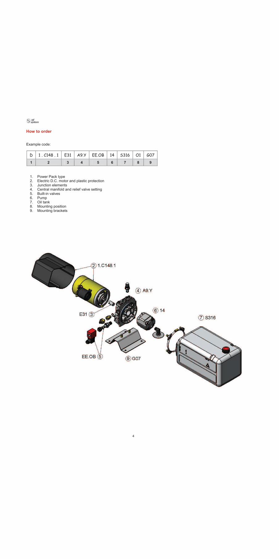
How to order
Example code:
D 1 . C148 . 1 E31 A9.Y EE.OB 14 S316 O1 G07
1 2 3 4 5 6 7 8 9
1. Power Pack type 2. Electric D.C. motor and plastic protection 3. Junction elements 4. Central manifold and relief valve setting 5. Built-in valves 6. Pump 7. Oil tank 8. Mounting position 9. Mounting brackets
5
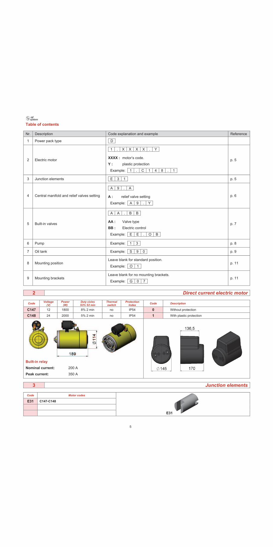
Table of contents
Nr. Description Code explanation and example Reference
1 Power pack type D
2 Electric motor
1 . X X X X . Y
XXXX : motor’s code.
Y : plastic protection
Example: 1 . C 1 4 8 . 1
p. 5
3 Junction elements E 3 1 p. 5
4 Central manifold and relief valves setting
A 9 . A
A : relief valve setting
Example: A 9 . Y
p. 6
5 Built-in valves
A A . B B
AA : Valve type
BB : Electric control
Example: E E . O B
p. 7
6 Pump Example: 1 3 p. 8
7 Oil tank Example: S 9 0 p. 9
8 Mounting position Leave blank for standard position.
Example: O 1p. 11
9 Mounting brackets Leave blank for no mounting brackets.
Example: G 0 7p. 11
2 Direct current electric motor
CodeVoltage
(V) Power
(W) Duty cicles S3% S2 min
Thermal switch
Protection Index
Code Description
C147 12 1800 8% 2 min no IP54 0 Without protection
C148 24 2000 5% 2 min no IP54 1 With plastic protection
Built-in relay
Nominal current: 200 A
Peak current: 350 A
3 Junction elements
Code Motor codes
E31 C147-C148
E31
6
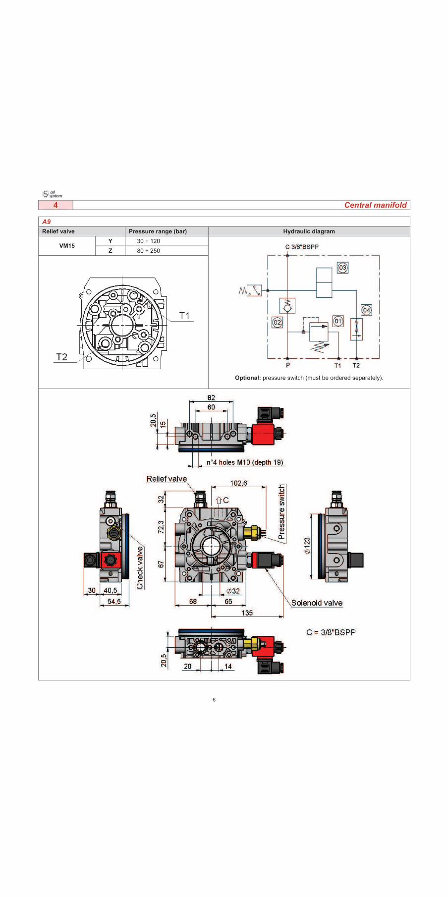
4 Central manifold
A9
Relief valve Pressure range (bar) Hydraulic diagram
Y 30 ÷ 120 VM15
Z 80 ÷ 250
Optional: pressure switch (must be ordered separately).
7
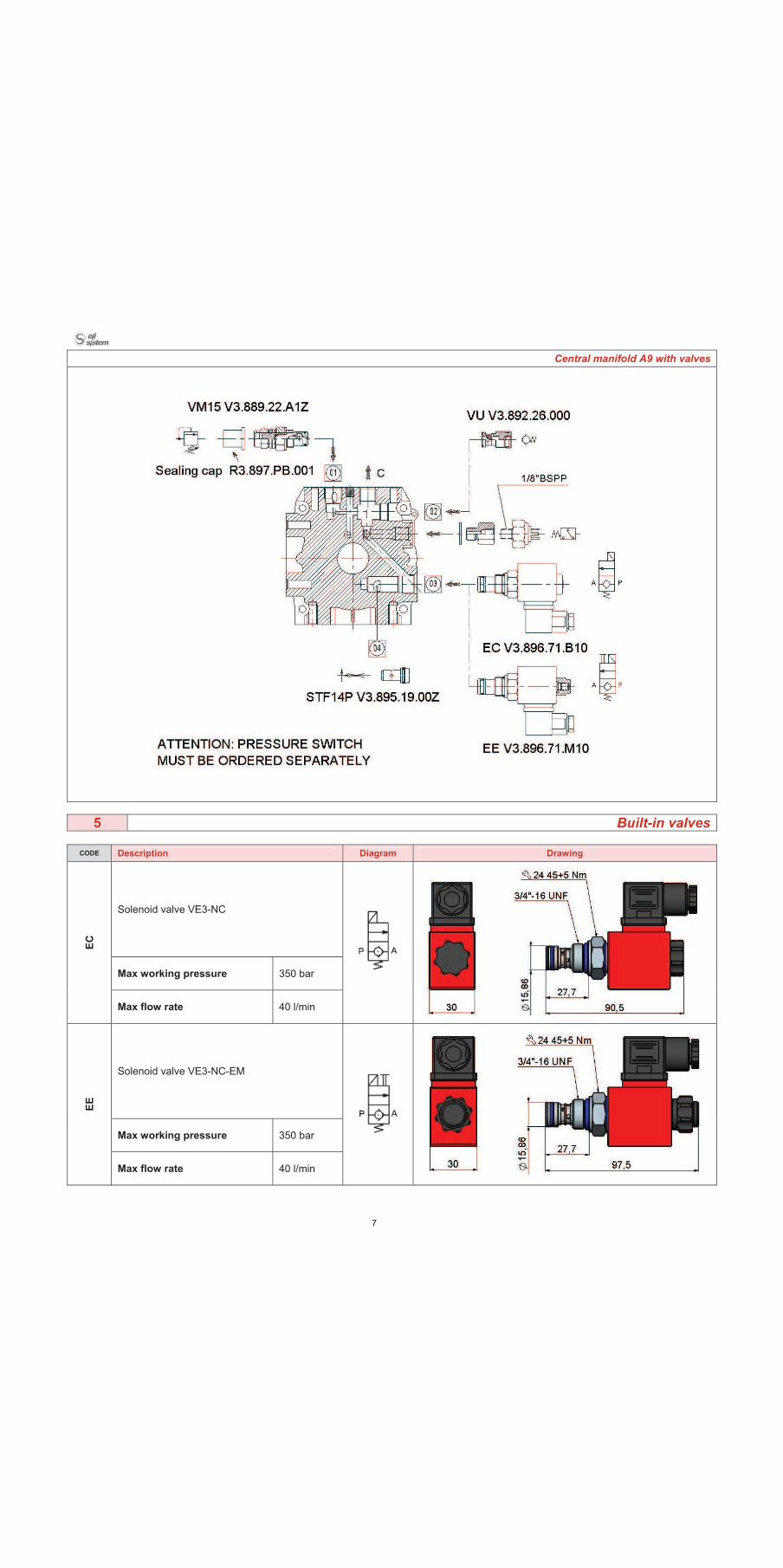
Central manifold A9 with valves
5 Built-in valves
CODE Description Diagram Drawing
Solenoid valve VE3-NC
Max working pressure 350 bar
EC
Max flow rate 40 l/min
Solenoid valve VE3-NC-EM
Max working pressure 350 bar
EE
Max flow rate 40 l/min
8
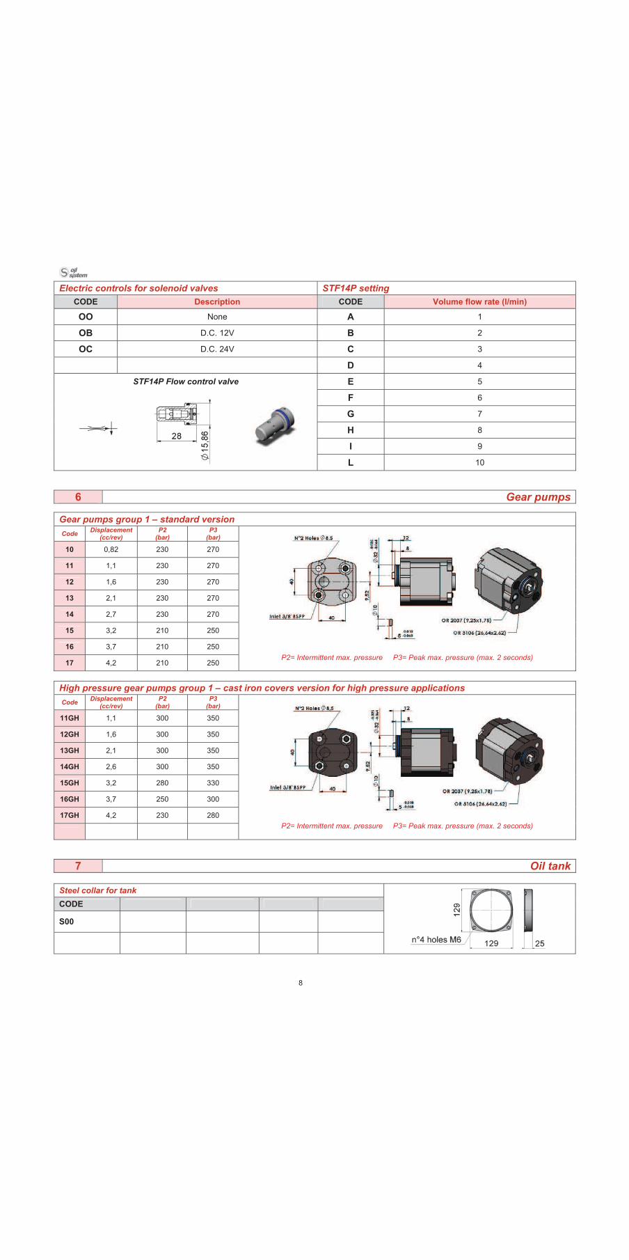
Electric controls for solenoid valves STF14P setting
CODE Description CODE Volume flow rate (l/min)
OO None A 1
OB D.C. 12V B 2
OC D.C. 24V C 3
D 4
STF14P Flow control valve E 5
F 6
G 7
H 8
I 9
L 10
6 Gear pumps
Gear pumps group 1 – standard version
CodeDisplacement
(cc/rev) P2
(bar) P3
(bar)
10 0,82 230 270
11 1,1 230 270
12 1,6 230 270
13 2,1 230 270
14 2,7 230 270
15 3,2 210 250
16 3,7 210 250
17 4,2 210 250P2= Intermittent max. pressure P3= Peak max. pressure (max. 2 seconds)
High pressure gear pumps group 1 – cast iron covers version for high pressure applications
CodeDisplacement
(cc/rev) P2
(bar) P3
(bar)
11GH 1,1 300 350
12GH 1,6 300 350
13GH 2,1 300 350
14GH 2,6 300 350
15GH 3,2 280 330
16GH 3,7 250 300
17GH 4,2 230 280
P2= Intermittent max. pressure P3= Peak max. pressure (max. 2 seconds)
7 Oil tank
Steel collar for tank
CODE
S00
9
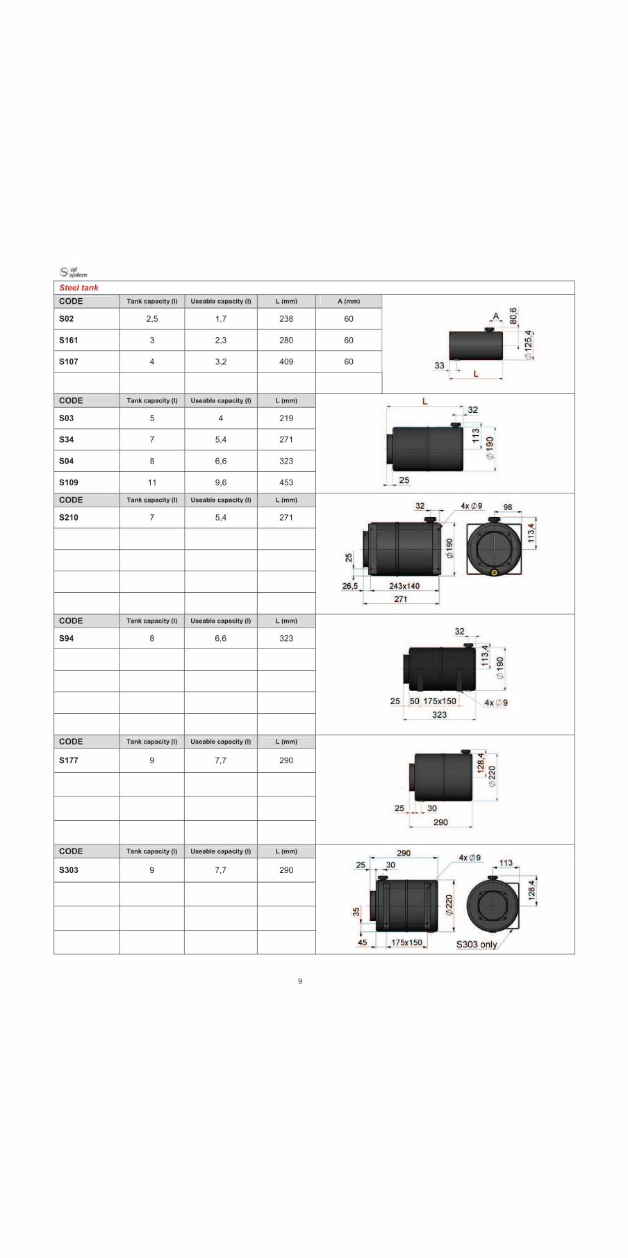
Steel tank
CODE Tank capacity (l) Useable capacity (l) L (mm) A (mm)
S02 2,5 1,7 238 60
S161 3 2,3 280 60
S107 4 3,2 409 60
CODE Tank capacity (l) Useable capacity (l) L (mm)
S03 5 4 219
S34 7 5,4 271
S04 8 6,6 323
S109 11 9,6 453
CODE Tank capacity (l) Useable capacity (l) L (mm)
S210 7 5,4 271
CODE Tank capacity (l) Useable capacity (l) L (mm)
S94 8 6,6 323
CODE Tank capacity (l) Useable capacity (l) L (mm)
S177 9 7,7 290
CODE Tank capacity (l) Useable capacity (l) L (mm)
S303 9 7,7 290
10
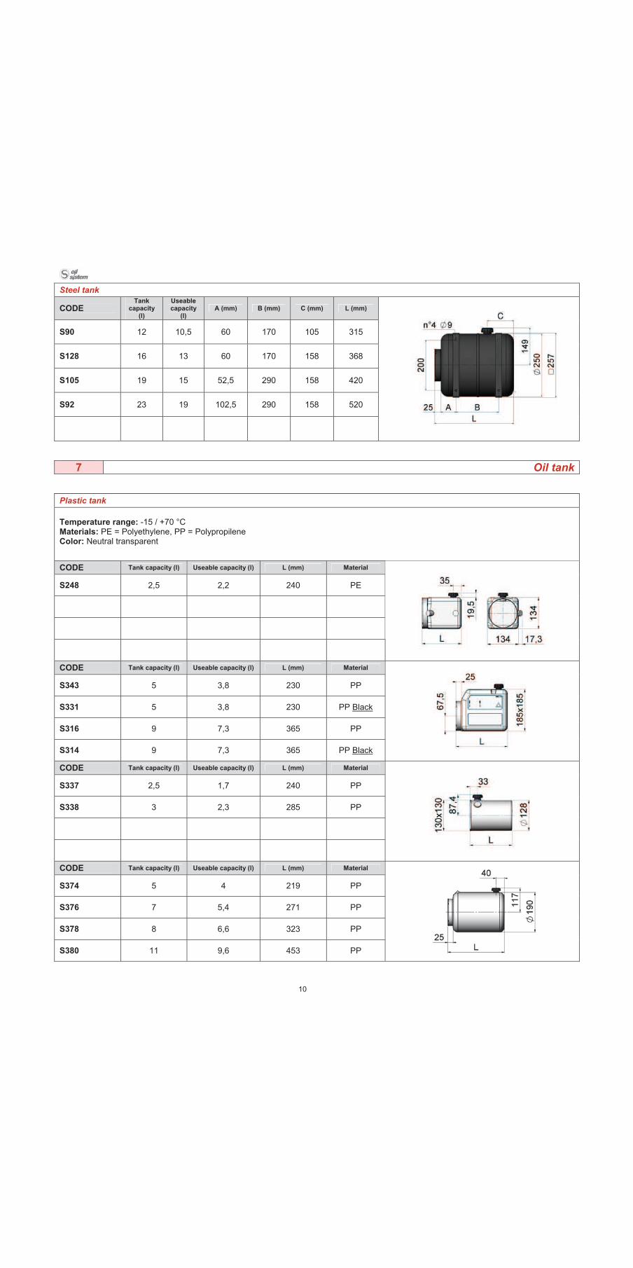
Steel tank
CODETank
capacity (l)
Useablecapacity
(l)A (mm) B (mm) C (mm) L (mm)
S90 12 10,5 60 170 105 315
S128 16 13 60 170 158 368
S105 19 15 52,5 290 158 420
S92 23 19 102,5 290 158 520
7 Oil tank
Plastic tank
Temperature range: -15 / +70 °C Materials: PE = Polyethylene, PP = Polypropilene Color: Neutral transparent
CODE Tank capacity (l) Useable capacity (l) L (mm) Material
S248 2,5 2,2 240 PE
CODE Tank capacity (l) Useable capacity (l) L (mm) Material
S343 5 3,8 230 PP
S331 5 3,8 230 PP Black
S316 9 7,3 365 PP
S314 9 7,3 365 PP Black
CODE Tank capacity (l) Useable capacity (l) L (mm) Material
S337 2,5 1,7 240 PP
S338 3 2,3 285 PP
CODE Tank capacity (l) Useable capacity (l) L (mm) Material
S374 5 4 219 PP
S376 7 5,4 271 PP
S378 8 6,6 323 PP
S380 11 9,6 453 PP
11
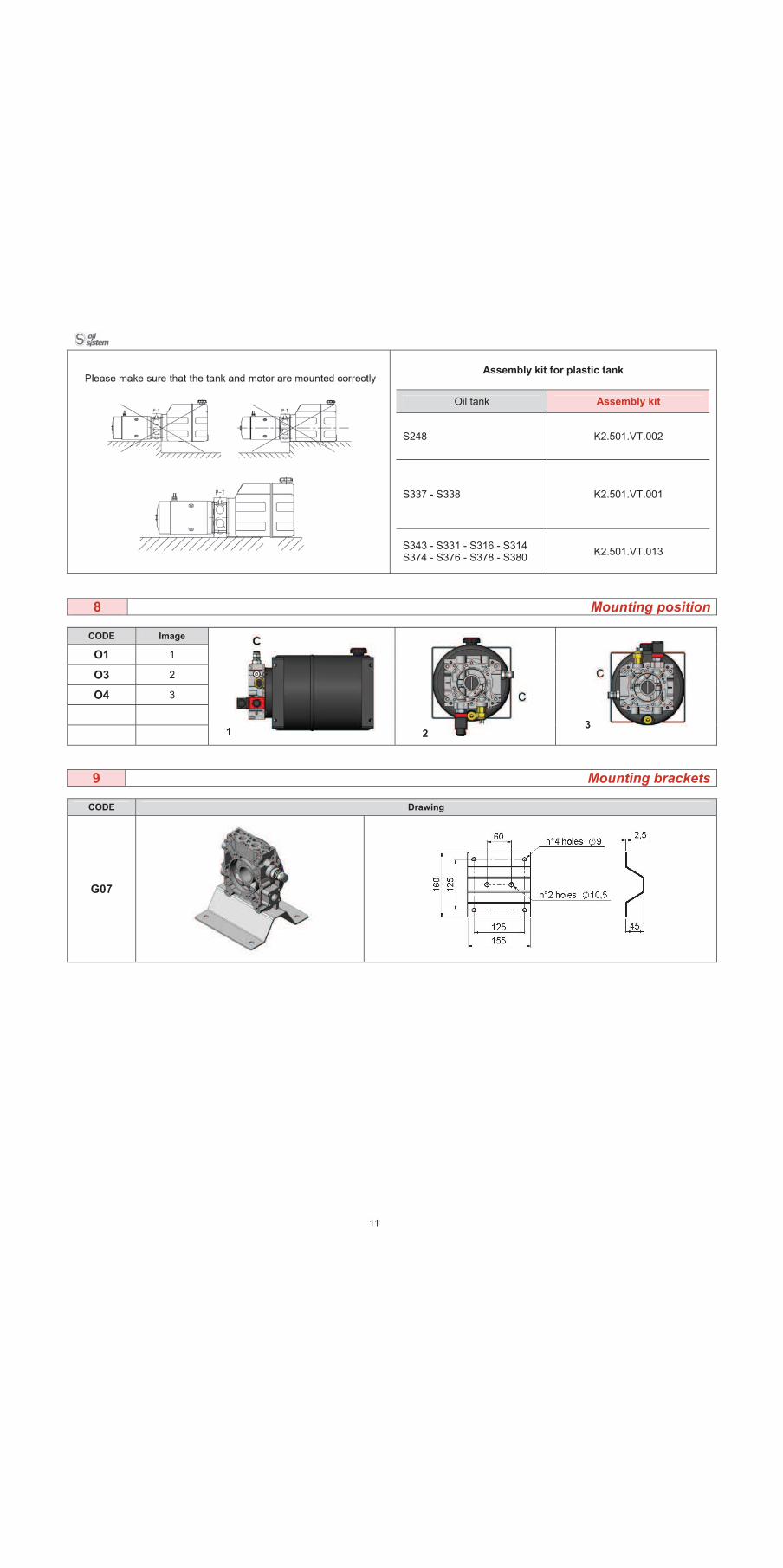
Assembly kit for plastic tank
Oil tank Assembly kit
S248 K2.501.VT.002
S337 - S338 K2.501.VT.001
S343 - S331 - S316 - S314 S374 - S376 - S378 - S380
K2.501.VT.013
8 Mounting position
CODE Image
O1 1
O3 2
O4 3
1 23
9 Mounting brackets
CODE Drawing
G07

12
Accessories
End stroke limit switch
R3.897.FC.082 push-type
R3.897.FC.083 pull-type
Pressure-switch normally closed
C1.647.02.000
Electric panel control
R3.897.ST.007
K2.501.S1.218 Electric cables for single acting cylinder
13
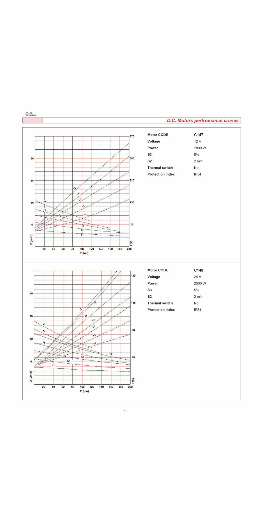
D.C. Motors perfromance cruves
Motor CODE C147
Voltage 12 V
Power 1800 W
S3 8%
S2 2 min
Thermal switch No
Protection Index IP54
Motor CODE C148
Voltage 24 V
Power 2000 W
S3 5%
S2 2 min
Thermal switch No
Protection Index IP54
14
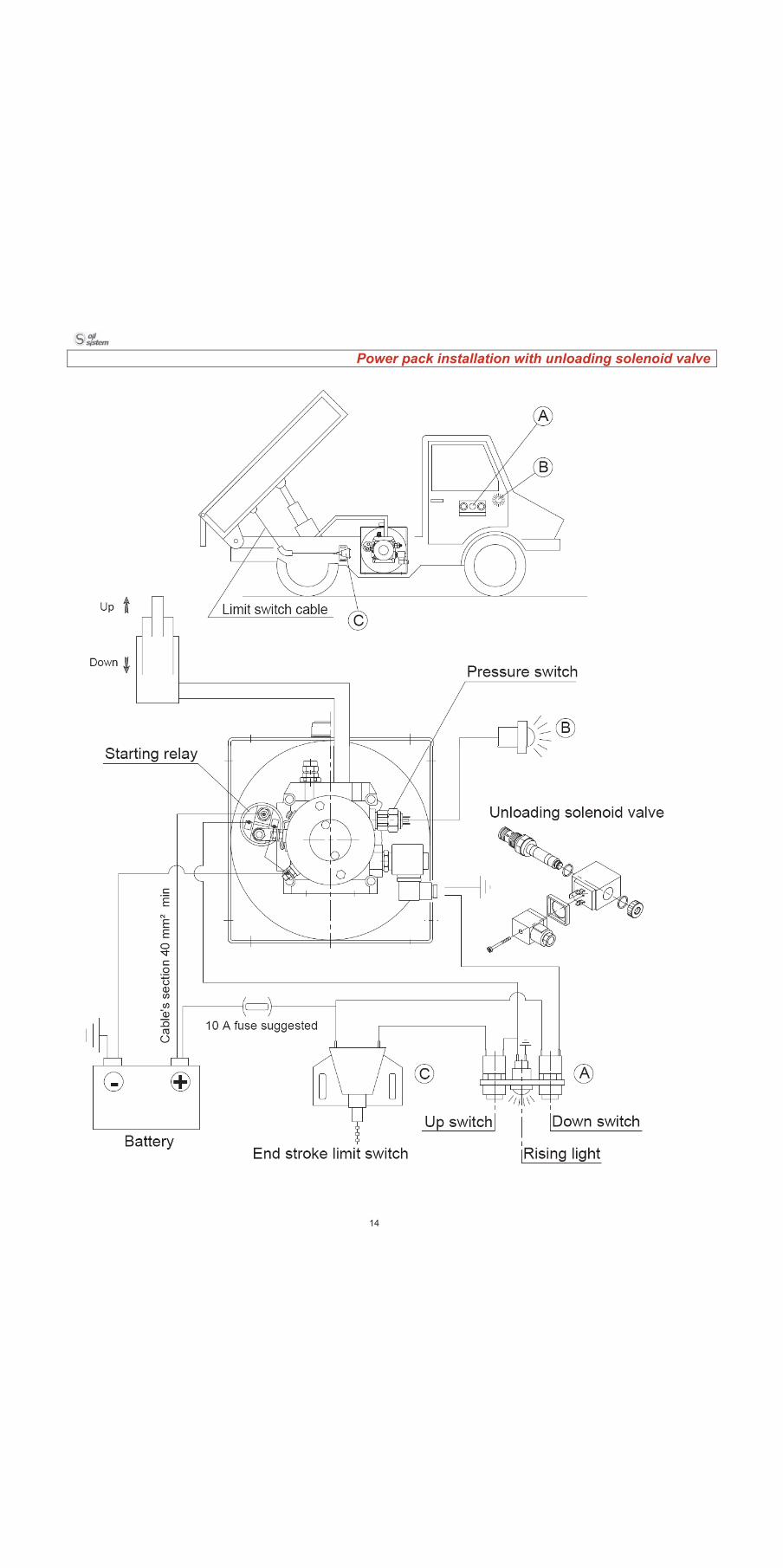
Power pack installation with unloading solenoid valve

Notes:
15