Central Plant Air Systems: Keeping the Heart and Lung … · Central Plant Air Systems: Keeping the...
55
Click To Edit Master Title Style Central Plant Air Systems: Keeping the Heart and Lungs Healthy Better Buildings Summit May 2016
Transcript of Central Plant Air Systems: Keeping the Heart and Lung … · Central Plant Air Systems: Keeping the...

Click To Edit Master Title Style
Central Plant Air Systems: Keeping the Heart and Lungs Healthy
Better Buildings Summit
May 2016

Introductions
Michael Deru National Renewable Energy Laboratory
New Resources
Mark Hydeman Continual, Inc.
ASHRAE Guideline 36
Michael Ivanovich AMCA
Fan value with AMCA
Steve Dikeman AcoustiFLO, LLC
Getting the most of your fans

Central Plant Resource Map
4

Click to edit Master title style Central Plant Resource Map
5

How Well are Your Systems Performing?
6
Compare your building end uses to a range of standard benchmarks
Your Building

Michael Ivanovich, AMCA Steve Dikeman, AcoustiFLO, LLC

How to Save Energy in Air Systems

9
Michael Ivanovich, Senior Director, AMCA international [email protected] Steve Dikeman, President, AcoustiFLO [email protected]
Presented by

Ivanovich
About AMCA
System Effect
10
Learning Objectives
Dikeman
System Leakage
Right-Sizing Fans
Air Movement and Control Association International, founded in 1917
Not-for-profit manufacturers association of fans, dampers, louvers and other air movement and control products
Mission is to promote the health, growth and integrity of the industry
11
What is AMCA?

How AMCA’s Certified Ratings Program works:
Companies send products to AMCA for testing
AMCA tests products for parameters specified
AMCA checks its data against manufacturer literature
After certification, the product
Is licensed to bear AMCA’s seal
Is listed in AMCA’s online database
Undergoes check tests every three years
12
What is the AMCA Certified Ratings Program?

Installed duct configuration does not match tested duct configuration
13 System Effect: 1ST Definition

Even when the tested duct configuration matches the installed duct configuration, improper duct design can
introduce adverse flow conditions
16 System Effect: 2nd Definition


44
Minimum 2.5 duct diameters on outlet
Minimum 3 to 5 duct diameters on Inlet
Avoid inlet swirl
Rules of Thumb

45
Recommendations
1. Allow enough space in the building design for fan connections
2. Use allowances in design calculations when space is a factor
3. Reference AMCA 201
4. Include allowance for the effect of all accessories and appurtenances

Establish level of tightness needed
Specify air system components and sealants that perform together as a system
Select a testing standard that ensures the leakage objective is met
2012 ASHRAE Handbook—HVAC Systems and Equipment and 2013 ASHRAE Handbook—Fundamentals
21
System Leakage

Efficient
Quiet
Cheap
…Select any two!
22
Right Sizing Fans

Variable volume air systems = variable speed systems
Constant volume systems with variable pressures = variable speed systems
Night setback, after hours, weekend modes are candidates for variable speed
Constant speed air systems are neither constant volume or constant pressure
23
Constant Speed Air Systems

Minimal reduction in speed offers a massive reduction in input power
90% speed 73% impeller bhp
80% speed 50% impeller bhp
70% speed 34% impeller bhp
60% speed 22% impeller bhp
24
Variable Speed Air Systems
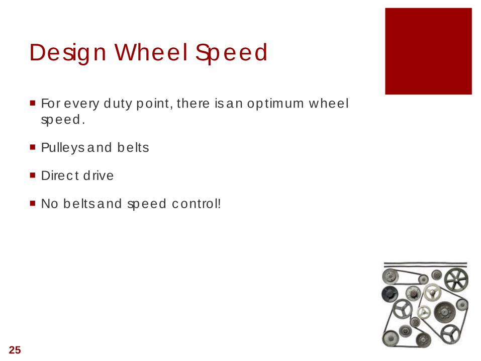
For every duty point, there is an optimum wheel speed.
Pulleys and belts
Direct drive
No belts and speed control!
25
Design Wheel Speed

26
Belt Loss
3% to 10% 4% to 15% 6% to 22%

Design flow (includes a safety factor)
Design pressure (includes a safety factor)
Filter loading (all filters at the same time)
Plus another safety factor?
Input flow and pressure into selection software
27
Right-Sizing Fans

Fan diameter (inches) Input power (bhp) 30” 10.2 27” 10.3 24” 10.7 22” 11.9 20” 14.4
28
Right-Sizing Fans
All selections require a 15 HP motor. Unless input power is defined which wheel will you get? – the cheapest/smallest A 42% difference in energy consumption “It’s only 4.2bhp” (12,000cfm at 4”)

29
Fans are Simple Machines

30
The smallest wheel – design flow & 80% pressure. Fan efficiency down yet another 5% from the selection point
Fans are Simple Machines

31
Largest wheel – design flow & 80% pressure. Still near design efficiency
Fans are Simple Machines

Imperative to specify a maximum absorbed power
“Bigger wheel” minus “slower speed” isn’t always better
For VAV supply fans, reset minimum pressure set point
Evaluate the fan curve, not just the tabular output
32
Right-Sizing Fans

Mark Hydeman Continual, Inc.

© 2015, Continual Energy Inc., all rights reserved.
Presentation Agenda:
• Overview of Guideline 36P
• How GPC 36P Will Improve The Industry
• How To Get Involved
ASHRAE Guideline 36P Best of Class Sequences for HVAC Systems Speaker: Mark Hydeman, PE, ASHRAE Fellow Chair of GPC 36 (and Principal Investigator for RP-1455)
Mark Hydeman, PE, ASHRAE Fellow Principal
Continual Energy Inc. Chair, GPC 36
[email protected] Cell Number 415-602-9982
www.continual.net

© 2015, Continual Energy Inc., all rights reserved.
About Continual Energy Inc.
Continual Energy Inc. solves your most critical building energy needs. From HVAC system optimization technology, to engineering studies, performance guarantees and financing to monitoring based commissioning technology, we deliver and sustain energy and cost savings across various building applications.
35
Philip Kennedy Principal, Toronto
Jason Zwicker Principal, Toronto
Josh Kahan Principal, Montreal
Mark Hydeman Principal, California
Dr. Alex Lee Sales, Singapore

© 2015, Continual Energy Inc., all rights reserved.
Pow
er In
put (
kW)
Optimal Balance Between Equipment Energy and Water Temperature
0
Condenser Water Temperature (°F)
66.9 67.4 68.1 68.9 69.9 71.3 73.2 76.2
30
60
90
120
150
180
210
240 Coolin g Tow er
36
About Continual Energy Inc.
© 2015, Continual Energy Inc., all rights reserved.
Guideline 36 Overview
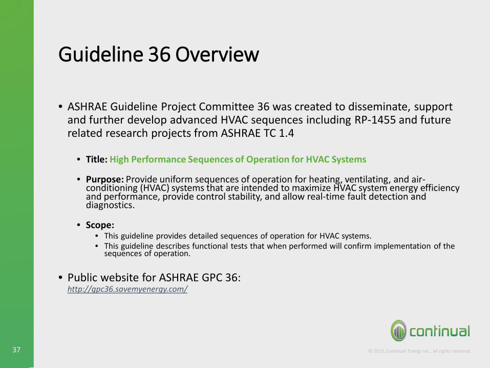
• ASHRAE Guideline Project Committee 36 was created to disseminate, support and further develop advanced HVAC sequences including RP-1455 and future related research projects from ASHRAE TC 1.4
• Title: High Performance Sequences of Operation for HVAC Systems
• Purpose: Provide uniform sequences of operation for heating, ventilating, and air-conditioning (HVAC) systems that are intended to maximize HVAC system energy efficiency and performance, provide control stability, and allow real-time fault detection and diagnostics.
• Scope: • This guideline provides detailed sequences of operation for HVAC systems. • This guideline describes functional tests that when performed will confirm implementation of the
sequences of operation.
• Public website for ASHRAE GPC 36: http://gpc36.savemyenergy.com/
37

© 2015, Continual Energy Inc., all rights reserved.
Guideline 36 Overview
• ASHRAE Guideline Project Committee 36 was created to disseminate, support and further develop advanced HVAC sequences including RP-1455 and future related research projects from ASHRAE TC 1.4
• Title: High Performance Sequences of Operation for HVAC Systems
• Purpose: Provide uniform sequences of operation for heating, ventilating, and air-conditioning (HVAC) systems that are intended to maximize HVAC system energy efficiency and performance, provide control stability, and allow real-time fault detection and diagnostics.
• Scope: • This guideline provides detailed sequences of operation for HVAC systems. • This guideline describes functional tests that when performed will confirm implementation of the
sequences of operation.
• Public website for ASHRAE GPC 36: http://gpc36.savemyenergy.com/
38

© 2015, Continual Energy Inc., all rights reserved.
Guideline 36 Overview
• ASHRAE Guideline Project Committee 36 was created to disseminate, support and further develop advanced HVAC sequences including RP-1455 and future related research projects from ASHRAE TC 1.4
• Title: High Performance Sequences of Operation for HVAC Systems
• Purpose: Provide uniform sequences of operation for heating, ventilating, and air-conditioning (HVAC) systems that are intended to maximize HVAC system energy efficiency and performance, provide control stability, and allow real-time fault detection and diagnostics.
• Scope: • This guideline provides detailed sequences of operation for HVAC systems. • This guideline describes functional tests that when performed will confirm implementation of the
sequences of operation.
• Public website for ASHRAE GPC 36: http://gpc36.savemyenergy.com/
39
© 2015, Continual Energy Inc., all rights reserved.
Guideline 36 Overview
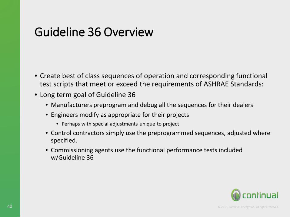
• Create best of class sequences of operation and corresponding functional test scripts that meet or exceed the requirements of ASHRAE Standards:
• Long term goal of Guideline 36 • Manufacturers preprogram and debug all the sequences for their dealers • Engineers modify as appropriate for their projects
• Perhaps with special adjustments unique to project
• Control contractors simply use the preprogrammed sequences, adjusted where specified.
• Commissioning agents use the functional performance tests included w/Guideline 36
40

© 2015, Continual Energy Inc., all rights reserved.
Guideline 36 Timeline
• First meeting June 2014 • First Draft (dry-side only) went out for Advisory Public Review in
June 2015: 14 Commenters, 114 Comments. • Voted for Publication Public Review in April of 2016.
8

© 2015, Continual Energy Inc., all rights reserved.
Guideline 36 Current Scope (RP-1455)
• Includes sequences for air systems (dry-side) • Sections:
• General logic (e.g. zone groups, zone mode, alarms, etc.) • Terminal Units: VAV(cooling-only and reheat), DDVAV & FCUs • AHUs & ACUs (single and multiple zone)
• Sequences developed and simulation tested in real control hardware under ASHRAE Research Project RP1455.
• A new research project was just approved to field test these SOOs and develop companion FPTs.
42

© 2015, Continual Energy Inc., all rights reserved.
Objectives
• Reduce Cost • Writing sequences, programming, and commissioning
• Reduce Errors • Unambiguous English-language sequences • Algorithms pretested and standardized • The GPC 36 committee will keep the document up to date
• Improve Energy Efficiency • Improve Code and Standard Compliance
• ASHRAE Standards 90.1 (energy efficiency), • 62.1 (ventilation), and • 55.1 (thermal comfort)
• Incorporate best of class performance (next slide)
43

© 2015, Continual Energy Inc., all rights reserved.
Innovations in GPC 36P
• Application of trim and respond controls for resets • Automatic fault detection and diagnostics (AFDD) based on NIST
Research • Hierarchical alarm suppression • Controls algorithms programmed and simulation tested in real
control hardware • Both written sequences and functional logic block representations
are available • Sequences include embedded application notes and examples.
44
= covered later
© 2015, Continual Energy Inc., all rights reserved.
trim
respond
trim
respond
trim
2 IGNORES
respond
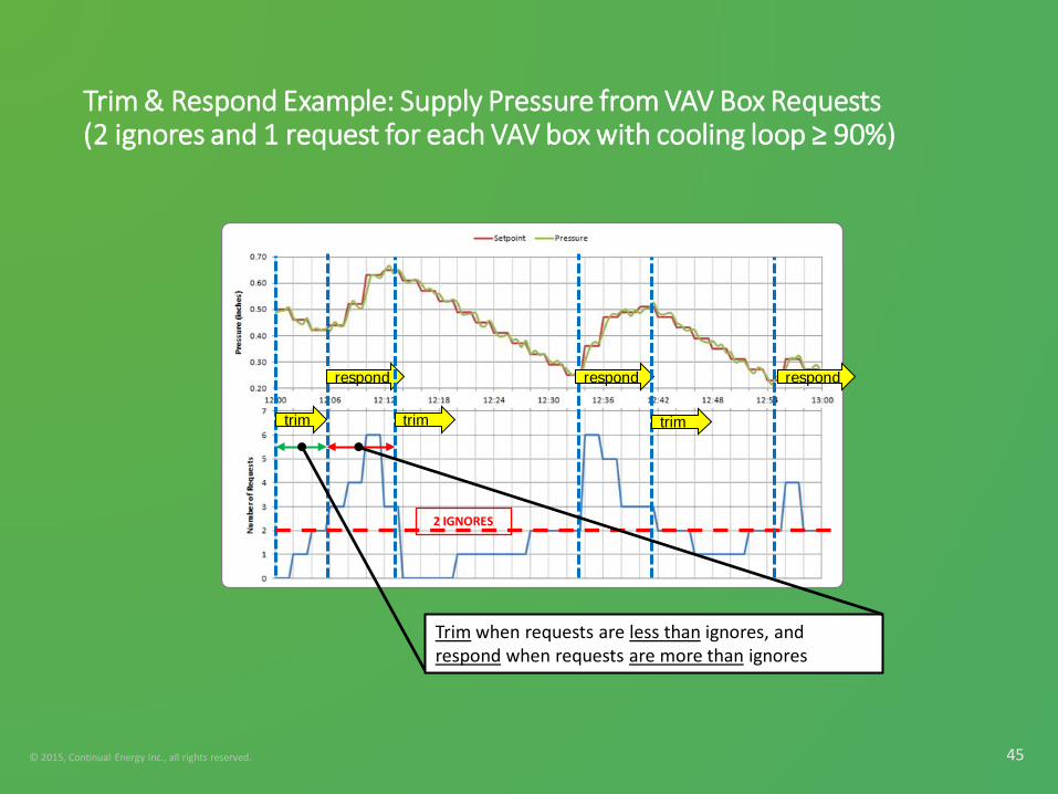
Trim & Respond Example: Supply Pressure from VAV Box Requests (2 ignores and 1 request for each VAV box with cooling loop ≥ 90%)
45
Trim when requests are less than ignores, and respond when requests are more than ignores

© 2015, Continual Energy Inc., all rights reserved.
T&R Rogue Zones
• A rogue zone is one that is always requesting more (more static pressure, colder CHW, or hotter HHW)
• Example causes: • Load added to a zone or removed with no change to the terminal unit size or settings • Starved zones due to inadequate air or hydronic distribution • Undersized fans, coils, pumps, etc. • Extreme set-point adjustments, and • Equipment failure (broken damper, valve) • No commissioning or items not caught in the “commissioning”
• This drives the reset loop to extremes and prevents energy savings. • You can alarm on request-hours (following slides)
46

© 2015, Continual Energy Inc., all rights reserved.
General Logic: T&R Rogue Zones
47
0
20
40
60
80
100
6/27/06 3:00 6/27/06 6:00 6/27/06 9:00 6/27/06 12:00 6/27/06 15:00 6/27/06 18:00 6/27/06 21:00
Cool
ing
Loop
Out
put (
%)
VAV2-20 VAV2-21 VAV2-11 VAV2-22 VAV2-23 VAV2-24 VAV2-25VAV2-27 VAV2-30 VAV2-31 VAV2-6 VAV2-7 VAV2-28 VAV2-9
VAV2-9 is a rogue zone.
Rogue zones can be automatically detected by alarming on request-hours.

© 2015, Continual Energy Inc., all rights reserved.
General Logic: Trim and Respond Parameters
48

© 2015, Continual Energy Inc., all rights reserved.
General Logic: T&R Rogue Zones
49
Finding rogue zones requires operator attention.
BAS calculates Request-Hours for each zone, and alarms on high cumulative %-Request-Hours.

© 2015, Continual Energy Inc., all rights reserved.
AFDD: Automatic Fault Detection & Diagnostics
• Based on research by House, Bushby and Schein at NIST in 2000-2006.
• Only adopted for air handlers (APAR) in GPC 36P. VAV box FDD (VPACC) requires too much tuning.
• Finds fault and diagnosis by evaluating equations (mostly energy balance).
50

© 2015, Continual Energy Inc., all rights reserved.
Hierarchical Alarm Suppression
• A VAV reheat box has three sources of up-steam control: • Air pressure • Air temperature, and • Reheat coil source (electric or hot-water)
• If the upstream source is in alarm (e.g. the AHU fan trips) the zone temperature alarms are suppressed.
• In the zone alarm logic you disable the cooling alarm if the upstream source (fan, DX unit or chiller) has tripped.
51

© 2015, Continual Energy Inc., all rights reserved.
Related ASHRAE Research
• RP-1587 Control Loop Performance Assessment (complete)
• RP-1746 Field Validation of RP-1455 and development of FPTs (awarded in December 2015)
• RP-1747 Implementation of RP-1547 CO2-based Demand Controlled Ventilation for Multiple Zone HVAC Systems (awarded in December 2015)
• WS-1711 Advanced Sequences of Operation for HVAC Systems – Phase 2 Central Plants and Hydronic Systems (approved for bid in Spring of 2016).
52

© 2015, Continual Energy Inc., all rights reserved.
Related ASHRAE Research
• RP-1587 Control Loop Performance Assessment (complete)
• RP-1746 Field Validation of RP-1455 and development of FPTs (awarded in December 2015)
• RP-1747 Implementation of RP-1547 CO2-based Demand Controlled Ventilation for Multiple Zone HVAC Systems (awarded in December 2015)
• WS-1711 Advanced Sequences of Operation for HVAC Systems – Phase 2 Central Plants and Hydronic Systems (approved for bid in Spring of 2016).
• Kudos to Steve Taylor my ex-partner who had and executed the vision
53

© 2015, Continual Energy Inc., all rights reserved.
Guideline 36 How to Get Involved
• If you are interested in participating in GPC 36, join monthly net meetings.
• Generally the 2nd Thursday of the month from 8:00 AM to 12:00 PM PST (11:00 AM to 3:00 PM EST).
• Meeting details on website: http://gpc36.savemyenergy.com/
54

© 2015, Continual Energy Inc., all rights reserved. 55
Thank you! Any questions?
Mark Hydeman [email protected]

Thank you!
Mark Hydeman, Continual, Inc. [email protected]
Michael Ivanovich, AMCA [email protected] Steve Dikeman, AcustiFLO, LLC [email protected]
Michael Deru, National Renewable Energy Laboratory [email protected]
56