CENTRAL / HEADQUATERS EXPORTACIÓN / EXPORT …suasanamentari.com/pdf/5. Catalogue - OFFSHORE...
30
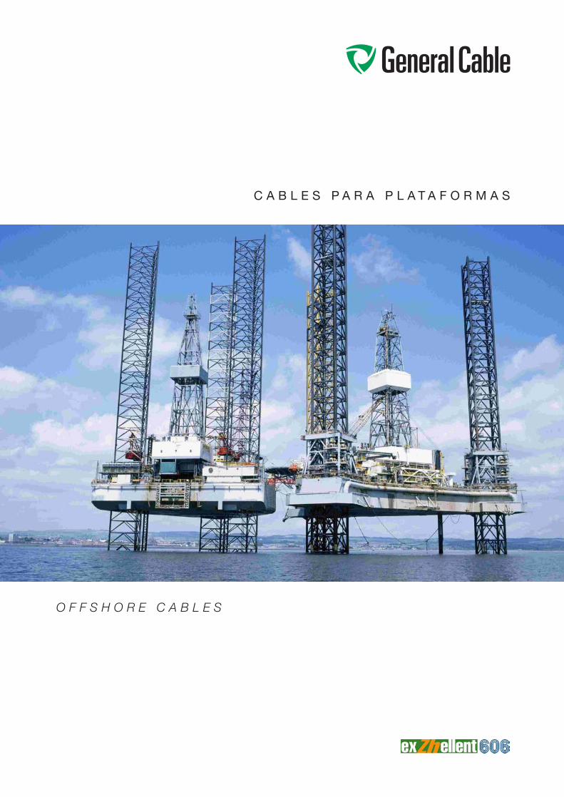
CABLES PARA PLATAFORMAS OFFSHORE CABLES
Transcript of CENTRAL / HEADQUATERS EXPORTACIÓN / EXPORT …suasanamentari.com/pdf/5. Catalogue - OFFSHORE...
C A B L E S P A R A P L A T A F O R M A S
CA
BL
ES
PA
RA
IN
DU
ST
RIA
NA
VA
LC
AB
LE
S P
AR
A I
ND
US
TR
IA N
AV
AL
CA
BL
ES
PA
RA
IN
DU
ST
RIA
NA
VA
L
O F F S H O R E C A B L E S
MA
RIN
E A
ND
OF
FS
HO
RE
CA
BL
ES
MA
RIN
E A
ND
OF
FS
HO
RE
CA
BL
ES
MA
RIN
E A
ND
OF
FS
HO
RE
CA
BL
ES
ATENCIÓN AL CLIENTETEL.:+34 932 279 700FAX :+34 900 210 486
CUSTOMER SERVICETEL.:+34 932 279 700FAX : +34 932 279 719www.generalcable.es
CENTRAL / HEADQUATERS
Casanova, 150 - 08036 BARCELONATel.: +34 93 227 97 00 - Fax: +34 93 227 97 [email protected]
ZONAS IBERIA / BRANCHES IBERIA
ANDALUCÍAEDIFICIO CENTRISGlorieta Fernando Quiñones, Planta 3ª Módulo 1841940-TOMARES (SEVILLA)Tel.: +34 954 99 95 18 - Fax: +34 954 15 61 [email protected]álagaTel. Móvil: +34 626 014 918 - Fax: +34 95 225 99 [email protected]
CENTROÁvila, Badajoz, Cáceres, Ciudad Real,Guadalajara, Madrid, Segovia y ToledoAvda. Ciudad de Barcelona, 81 A, 4º B28007 MADRIDTel.: +34 91 309 66 20 - Fax: +34 91 309 66 [email protected], León, Palencia, Salamanca,Valladolid y ZamoraTel. Móvil: +34 609 154 594Fax: +34 983 24 96 [email protected]
LEVANTEAlbacete, Comunidad Valenciana, Cuenca y MurciaCirilo Amorós, 27 - 6º C - 46004 VALENCIATel.: +34 96 350 92 58 - Fax: +34 96 352 95 [email protected]
NORDESTEAndorra, Aragón, Baleares y CataluñaAragón, 177-179, 2º planta - 08011 BARCELONATel.: +34 93 467 85 78 - Fax: +34 93 467 46 [email protected]
NORTEÁlava, Asturias, Cantabria y VizcayaJuan de Ajuriaguerra, 26 - 48009 BILBAOTel.: +34 94 424 51 76 - Fax: +34 94 423 06 [email protected]úzcoa, La Rioja, Navarra, SoriaTel.: +34 629 34 85 22 - Fax +34 948 23 46 [email protected]ón GALICIABESIGA COMERCIAL, S.L.Av. Tierno Galván, 11215178 MAIANCA - OLEIROS (La Coruña)Tel.: +34 981 61 71 94 - Fax: +34 981 61 74 [email protected]
Representación CANARIASÁngel Guerra, 23 - 1º35003 LAS PALMAS DE GRAN CANARIATel.: +34 928 36 11 57 - Fax: +34 928 36 44 [email protected]
PORTOR. Gonçalo Cristovão, 312 - 4º B e C4000-266 PORTOTel.: +351 223 392 350 - Fax: +351 223 323 878
EXPORTACIÓN / EXPORT
Casanova, 150 - 08036 BARCELONA (Spain)Tel.: + 34 93 227 97 24 - Fax: + 34 93 227 97 [email protected]
FACTORÍAS / FACTORIES
ABRERA (España)Carrer del Metall, 4 (Polígon Can Sucarrats) - 08630 ABRERA (Barcelona)Tel.: +34 93 773 48 00 - Fax: +34 93 773 48 48
MANLLEU (España)Ctra. Rusiñol, 63 - 08560 MANLLEU (Barcelona)Tel.: +34 93 852 02 00 - Fax: +34 93 852 02 22
MONTCADA I REIXAC (España)Ctra. de Ribas, Km. 13,250 - 08110 MONTCADA I REIXAC (Barcelona)Tel.: +34 93 227 95 00 - Fax: +34 93 227 95 22
VITORIA (España)Portal de Bergara, 36 - 01013 VITORIA-GAZTEIZTel.: +34 945 261 100 - Fax: +34 945 267 146 - [email protected] - www.ecn.es
MONTEREAU (Francia)SILEC CABLE - Rue de Varennes Prolongée - 77876 MONTEREAU CEDEX (France)Tel.: +33 (0) 1 60 57 30 00 - Fax: +33 (0) 1 60 57 30 [email protected] - www.sileccable.com
MORELENA (Portugal)Av. Marquês de Pombal, 36-38 Morelena - 2715-055 PÊRO PINHEIRO (Portugal)Tel.: +351 219 678 500 - Fax: +351 219 271 942
NORDENHAM (Alemania)NSW - Kabelstraße 9-11 - D-26954 NORDENHAM (Deutschland)Tel.: +49 4731 82 0 - Fax: +49 4731 82 1301 - [email protected] - www.nsw.com
BISKRA (Argelia)ENICAB - Zone Industrielle - B.P. 131 07000 RP BISKRA (Algérie)Tel.: +213 033 75 43 21/22 - Fax: +213 033 74 15 19 - [email protected]
LUANDA (Angola)CONDEL - Fábrica de Condutores Eléctricos de Angola, SARL5ª Av Nº 9, Zona Industrial do Cazenga, Caixa Postal nº 3043 LUANDA (Angola)Tel.: +244 2 380076/7/8/9/17 - Fax +244 2 33 78 12 - [email protected]
INTERNACIONAL / INTERNATIONAL
ARGELIAENICAB02, Rue Amar Bouneghaz, El Biar 16032 ALGÉRIETelf: +213 21 92 70 47/48 - Fax: +213 21 92 70 44 - [email protected]
EGIPTO6, Al Sebak st., # 91, Heliopolis, CAIRO (Egypt)Tel.: +202 263 79094 - Fax: +202 2241 9326 - [email protected]
EMIRATOS ÁRABES UNIDOSOffice No. 904 , 9Th FloorAl Salmeen Golden Tower Building - Electra Street, ABU DHABI - UAETel.: +971 2 6434666 - Fax:+ 971 2 6434667
NORUEGARandemveien 17 - 1540 VESTBY (Norway)Tel.: +47 64955900 - Fax: +47 64955910 - [email protected]
REINO UNIDORegus Management Ltd. Victory House, 400 Pavillion DriveNorthampton Business Park, Northampton - NN4 7PA, UKTel.: +44 (0) 1604 521061 - Fax: +44 (0) 1604 814770 - [email protected]
RUSIARussia, MOSCOW, 117997, Profsouznaya str., 65, build 1, office 5Tel.: +7 495 617 00 05 - Fax: +7 495 617 00 06 - [email protected]
AGENCIAS / AGENCIES
ARGENTINAFrancisco Beiró 1490 - Florida Este 1602 - BUENOS AIRES (Argentina)Tel.: +54 11 4760 6088 - Fax: +54 11 4761 0251 - e-mail: [email protected]
FRANCIADOMEX Cabling s.a.s - 43, rue de Vincennes - 93100 MONTREUIL (France)Tel.: +33 1 60 62 51 45 - Fax: +33 1 60 62 51 49 - [email protected]
ITALIASalvaneschi E.e.R.&C.S.A. - Via Pelizza da Volpedo, 2020092 CINISELLO BALSAMO - MILANO (Italy)Tel.:+39 02 660 49494 - Fax:+39 02 660 49489 - [email protected]
PRESENTACIÓNFOREWORD
1
Una de las mayores compañías delsector a nivel mundial.
General Cable Corporation es una de las compañías
líderes en fabricación de cable a nivel mundial. Con
su actividad ha contribuido y contribuye decisiva-
mente en el progreso y la mejora de la calidad de vida
de las personas. Y es que, a través de la innovación y
la tecnología, General Cable está presente en el desa-
rrollo y la evolución de la sociedad.
Con unas ventas superiores a 3400 millones de euros,
46 fábricas y con más de 13000 trabajadores que
proporcionan servicio a una red global de clientes en
todo el mundo, General Cable Corporation es una
empresa en constante expansión y desarrollo, inte-
grada por General Cable Norteamérica, General
Cable Europa y Norte de África, y Resto del Mundo.
La gama de cables de General Cable Corporation es
muy amplia, adaptándose a las necesidades de todos
los clientes, a través de su gran capacidad tecnológi-
ca, de producción, logística y de servicio post-venta.
Una empresa centenaria fiel a unos valores propios
basados en la satisfacción al cliente, la integridad en
todos sus acciones, el trabajo en equipo, la rapidez
en la entrega, la creatividad y la innovación y la mejo-
ra contínua. Y donde las personas son la principal
fuente de valor.
Así es General Cable. Una empresa que apuesta por
el futuro. Por la innovación. Por la sostenibilidad. Una
empresa dispuesta a cumplir su compromiso con la
sociedad y el medio ambiente.
One of the world’s biggest companies inthe sector.
General Cable Corporation is one of the world’s leading
cable manufacturing companies. In its work it has con-
tributed decisively to progress and improvements in
people’s quality of life. Through innovation and techno-
logy General Cable is present in the development and
evolution of society.
With sales of over 3,400 million euros, 46 manufacturing
locations and over 13,000 workers who provide service
to a global network of clients worldwide, General Cable
Corporation, a company in constant expansion and
development, comprises General Cable North America,
General Cable Europe and North Africa, and the Rest of
the World.
General Cable Corporation’s range of cables is very
extensive and adapts to the needs of all clients becau-
se of its great technological, production, logistics and
after-sales capacity.
The company has a hundred-year tradition and its own
values based on customer satisfaction, integrity in all it
does, teamwork, delivery speed, creativity and innova-
tion, and ongoing improvement, in which people are its
main source of value.
This is General Cable, a company with a commitment to
the future, to innovation, and to sustainability. It is a
company prepared to meet its commitment to society
and the environment.
3
ÍNDICEINDEX
SÍMBOLOS / SYMBOLS 4
INTRODUCCIÓN / INTRODUCTION 6
CABLES PARA PLATAFORMASOFFSHORE CABLES
Información técnica / Technical information 21
Guía de selección cables / Selection guide 27
Fichas técnicas de los cables / Cable data sheets 30
General Cable se reserva el derecho de alterar o modificar las especificaciones a la luz de futuros desarrollos técnicos.
General Cable reserves the right to alter or modify specifications and materials in the light of later technical development.
4
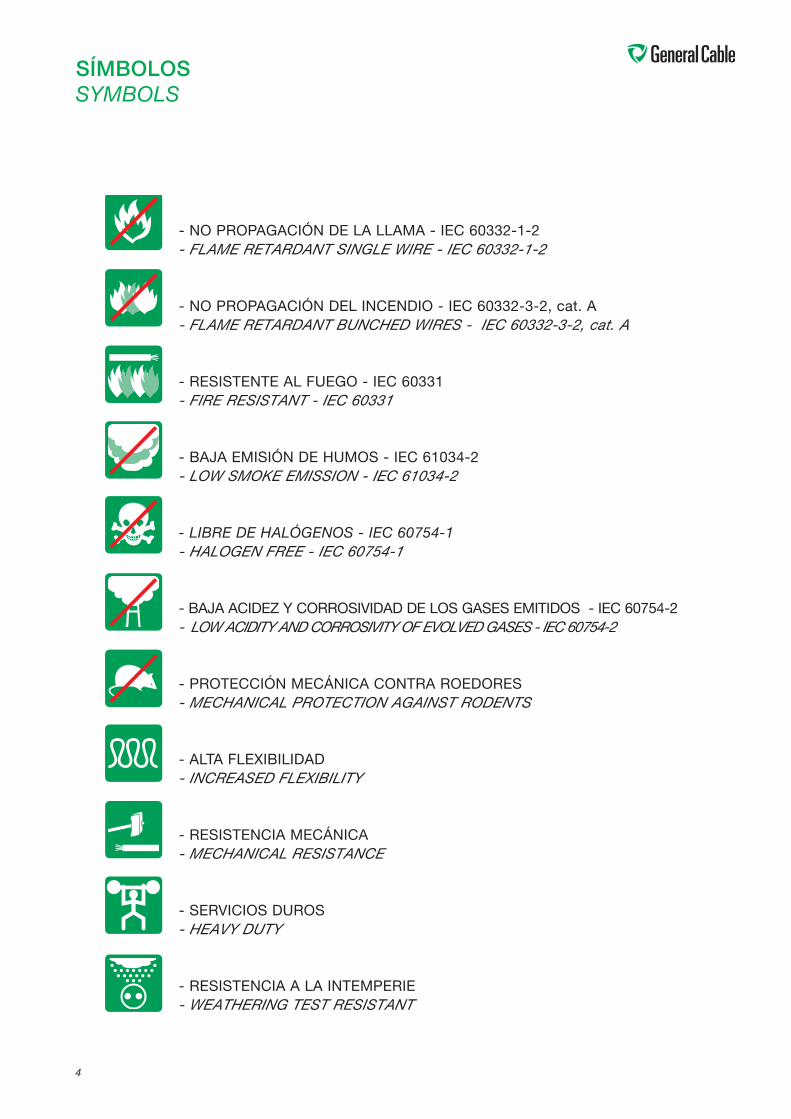
SÍMBOLOSSYMBOLS
- NO PROPAGACIÓN DE LA LLAMA - IEC 60332-1-2- FLAME RETARDANT SINGLE WIRE - IEC 60332-1-2
- NO PROPAGACIÓN DEL INCENDIO - IEC 60332-3-2, cat. A- FLAME RETARDANT BUNCHED WIRES - IEC 60332-3-2, cat. A
- RESISTENTE AL FUEGO - IEC 60331- FIRE RESISTANT - IEC 60331
- BAJA EMISIÓN DE HUMOS - IEC 61034-2- LOW SMOKE EMISSION - IEC 61034-2
- LIBRE DE HALÓGENOS - IEC 60754-1- HALOGEN FREE - IEC 60754-1
- BAJA ACIDEZ Y CORROSIVIDAD DE LOS GASES EMITIDOS - IEC 60754-2- LOWACIDITY ANDCORROSIVITYOF EVOLVEDGASES - IEC 60754-2
- PROTECCIÓN MECÁNICA CONTRA ROEDORES- MECHANICAL PROTECTION AGAINST RODENTS
- ALTA FLEXIBILIDAD- INCREASED FLEXIBILITY
- RESISTENCIA MECÁNICA- MECHANICAL RESISTANCE
- SERVICIOS DUROS- HEAVY DUTY
- RESISTENCIA A LA INTEMPERIE- WEATHERING TEST RESISTANT
5
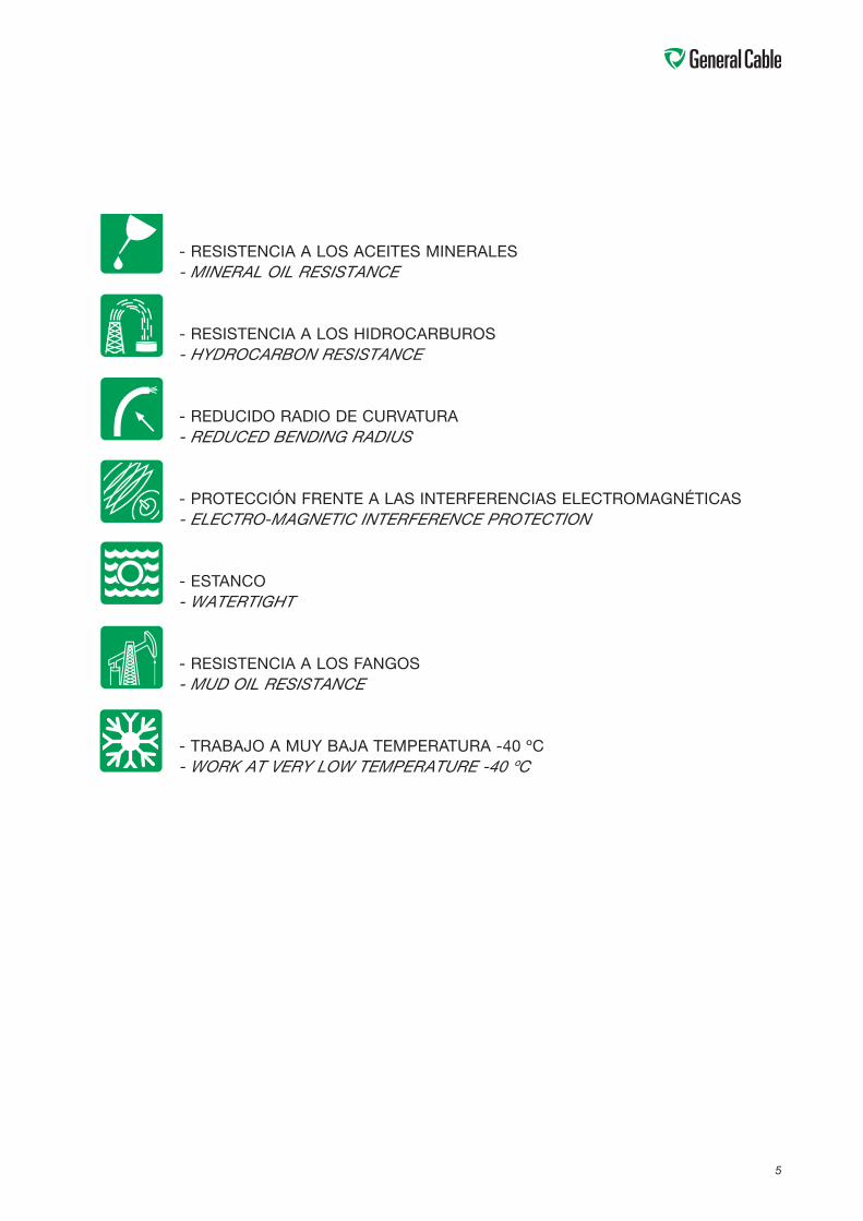
- RESISTENCIA A LOS ACEITES MINERALES- MINERAL OIL RESISTANCE
- RESISTENCIA A LOS HIDROCARBUROS- HYDROCARBON RESISTANCE
- REDUCIDO RADIO DE CURVATURA- REDUCED BENDING RADIUS
- PROTECCIÓN FRENTE A LAS INTERFERENCIAS ELECTROMAGNÉTICAS- ELECTRO-MAGNETIC INTERFERENCE PROTECTION
- ESTANCO- WATERTIGHT
- RESISTENCIA A LOS FANGOS- MUD OIL RESISTANCE
- TRABAJO A MUY BAJA TEMPERATURA -40 ºC- WORK AT VERY LOW TEMPERATURE -40 ºC
6
I N T R O D U C C I Ó NI N T R O D U C T I O N
CABLES PARA PLATAFORMASGeneral Cable presenta en este catálogo, sus series decables navales para energía, control e instrumentación eninstalaciones fijas en los buques y plataformas petrolíferas.
La seguridad de las personas y equipos es un elementofundamental que se tiene en cuenta en el diseño y cons-trucción de los cables Ezhhellent-606. Los compuestosutilizados son libres de halógenos, de baja acidez ycorrosividad de los gases emitidos y de baja opacidad delos humos emitidos durante la combustión de acuerdocon las correspondientes normas IEC. Esto permite unaevacuación rápida y segura en caso de incendio.
Los cables están diseñados para cumplir con las másestrictas normas de no propagación del incendio, impi-diendo la generación de focos secundarios aún en lascondiciones de mayor concentración de cables en con-diciones desfavorables.
Se dispone además de los diseños "resistentes al fuego"que a las propiedades citadas añaden la capacidad deseguir prestando servicio aún viéndose directamenteafectados por el fuego. Su aplicación a los servicios deseguridad permite que estos sigan funcionando aún encaso de incendio.
Los cables armados utilizan de forma standard la trenzade cobre estañado que aporta una buena protecciónmecánica y puede ser utilizada también en aplicacionesespecíficas como pantalla.
Los cables Exzhellent-606 pueden utilizarse en climasextremos, especialmente por su resistencia a las tempe-raturas muy bajas.
Este catálogo también incorpora diseños específicospara los cables de energía de los circuitos de baja ten-sión con variadores de frecuencia (VFD).
Los diseños de cables descritos en el presente catálogose han realizado de acuerdo con las siguientes normas yespecificaciones.
OFFSHORE CABLESIn this catalogue General Cable presents its series of ship-board energy, control and instrumentation cables for fixedinstallations on vessels and oil rigs.
The safety of people and equipment is a priority considera-tion in the design and construction of Ezhhellent-606cables. They are made from zero-halogen compounds witha low-acidity and -corrosivity of gases evolved and a lowopacity of fumes evolved during combustion, in accordan-ce with the corresponding IEC standards. They thereforeallow for quick, safe evacuation in the event of fire.
The cables are designed to comply with the strictest non-fire propagation standards and prevent the generation ofsecondary seats of fire even in circumstances of high cableconcentration in unfavourable conditions.
There are also "fire-resistant” designs that feature not onlythe above properties, but are also able to continue provi-ding service even when directly affected by fire. Their usein safety services enables the services to continue workingeven in situations of fire.
Reinforced cables feature standard tinned copper braidingthat provides good mechanical protection and may also beused in specific applications such as shielding.
Exzhellent-606 cables may be used in extreme climates,principally because of their resistance to very low tempera-tures.
This catalogue also includes specific designs for energycables used in low-voltage circuits with variable frequencydrives (VFD).
The cables described in this catalogue have been designedin accordance with the following standards and specifica-tions.
7
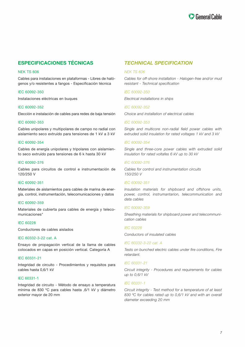
ESPECIFICACIONES TÉCNICAS
NEK TS 606
Cables para instalaciones en plataformas - Libres de haló-genos y/o resistentes a fangos - Especificación técnica
IEC 60092-350
Instalaciones eléctricas en buques
IEC 60092-352
Elección e instalación de cables para redes de baja tensión
IEC 60092-353
Cables unipolares y multipolares de campo no radial conaislamiento seco extruído para tensiones de 1 kV a 3 kV
IEC 60092-354
Cables de energía unipolares y tripolares con aislamien-to seco extruído para tensiones de 6 k hasta 30 kV
IEC 60092-376
Cables para circuitos de control e instrumentación de120/250 V
IEC 60092-351
Materiales de aislamientos para cables de marina de ener-gía, control, instrumentación, telecomunicaciones y datos
IEC 60092-359
Materiales de cubierta para cables de energía y teleco-municaciones"
IEC 60228
Conductores de cables aislados
IEC 60332-3-22 cat. A
Ensayo de propagación vertical de la llama de cablescolocados en capas en posición vertical. Categoría A
IEC 60331-21
Integridad de circuito - Procedimientos y requisitos paracables hasta 0,6/1 kV
IEC 60331-1
Integridad de circuito - Método de ensayo a temperaturamínima de 830 ºC para cables hasta ,6/1 kV y diámetroexterior mayor de 20 mm
TECHNICAL SPECIFICATION
NEK TS 606
Cables for off-shore installation - Halogen-free and/or mudresistant - Technical specification
IEC 60092-350
Electrical installations in ships
IEC 60092-352
Choice and installation of electrical cables
IEC 60092-353
Single and multicore non-radial field power cables withextruded solid insulation for rated voltages 1 kV and 3 kV
IEC 60092-354
Single and three-core power cables with extruded solidinsulation for rated voltafes 6 kV up to 30 kV
IEC 60092-376
Cables for control and instrumentation circuits150/250 V
IEC 60092-351
Insulation materials for shipboard and offshore units,power, control, instrumantarion, telecommunication anddata cables
IEC 60092-359
Sheathing materials for shipboard power and telecommuni-cation cables
IEC 60228
Conductors of insulated cables
IEC 60332-3-22 cat. A
Tests on bunched electric cables under fire conditions, Fireretardant.
IEC 60331-21
Circuit integrity - Procedures and requirements for cablesup to 0,6/1 kV
IEC 60331-1
Circuit integrity - Test method for a temperature of at least830 ºC for cables rated up to 0,6/1 kV and with an overalldiameter exceeding 20 mm
8
IEC 60331-2
Integridad de circuito - Método de ensayo a temperaturamínima de 830 ºC para cables hasta ,6/1 kV y diámetroexterior no mayor de 20 mm
IEC 60754-1
Ensayos de los gases desprendidos durante la combus-tión de materiales procedentes de los cables
IEC 60764-2
Determinación del grado de acidez de gases de losmateriales por medida del pH y la conductividad
IEC 61034-2
Medida de la densidad de los humos emitidos por cablesen combustión bajo condiciones definidas
IEC 60331-2
Circuit integrity - Test method for a temperature of at least830 ºC for cables rated up to 0,6/1 kV and with an overalldiameter not exceeding 20 mm
IEC 60754-1
Determination of the amount of halogen acid gas
IEC 60754-2
Determination of degree of acidity of gases
IEC 61034-2
Measurement of smoke density
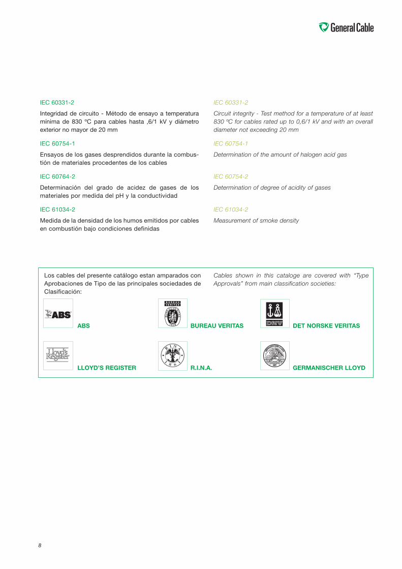
ABS BUREAU VERITAS DET NORSKE VERITAS
LLOYD’S REGISTER R.I.N.A. GERMANISCHER LLOYD
Los cables del presente catálogo estan amparados conAprobaciones de Tipo de las principales sociedades deClasificación:
Cables shown in this cataloge are covered with “TypeApprovals” from main classification societies:

9
APLICACIONESEn función de su utilización, los cables se distribuyen enlos siguientes grupos:
CABLES DE ENERGÍA DE BAJA TENSIÓN (NEK TS 606)
- Tensión asignada 0,6/1 kV.
- Composiciones hasta 4 conductores. Identificaciónpor coloración del aislamiento.
- Sin armar y armados con trenza de hilos de cobreestañado.
- Diseños disponibles para resistencia a los fangos y/oresistencia al fuego (integridad de circuito).
- Diseños disponibles para variadores de frecuencia(VFD).
CABLES DE ENERGÍA DE MEDIA TENSIÓN(NEK TS 606)
- Tensiones asignadas de 3,6/6 kV a 12/20 kV.
- Armados con trenza de hilos de cobre estañado.
- Diseños disponibles para resistencia a los fangos.
CABLES DE CONTROL (NEK TS 606)
- Tensión asignada 0,6/1 kV.
- Composición de 2 a 37 conductores. Identificaciónpor numeración.
- Armados con trenza de hilos de cobre estañado.
- Diseños disponibles para resistencia a los fangos y/oresistencia al fuego (integridad de circuito).
CABLES DE INSTRUMENTACIÓN (NEK TS 606)
- Cables de pares o tríos de tensión asignada 150/250 V.
- Conductores identificados por color y cintanumerada en cada par.
- Cable de dos pares sin pantalla individual, tieneformación de cuadrete / estrella
- Apantallado colectivo (trenza de cobre estañado) oindividual y colectiva (cinta Cu / poliéster y drenajeen cada par y trenza de cobre estañado colectiva).
APLICATIONSDepending on their use, the cables are distributed into thefollowing groups:
LOW VOLTAGE POWER CABLES (NEK TS 606)
- Power cables suitable for operation at up to andincluding 0.6/1 kV.
- Constructions up to and including 4 core. Colouredcore identification.
- Non armoured and armoured with tinned copper wirebraid.
- Available designs with mud resistance and/or fireresistance (circuit integrity).
- Available designs for variable frequency drives (VFD).
MEDIUM VOLTAGE CABLES (NEK TS 606)
- Cables for distribution of energy in voltages of 3,6/6 to12/20 kV.
- Armoured with tinned copper wire braid.
- Available designs with mud resistance.
CONTROL CABLES (NEK TS 606)
- Available from 2 to 37 cores. Identification bynumbering.
- Armoured with tinned copper wire braid.
- Available designs with mud resistance and/or fireresistance (circuit integrity).
INTRUMENTATION CABLES (NEK TS 606)
- Multiunit (pairs or triple core)
- Cores identified by colours and numbered tape in eachunit.
- Two pair cable without individual screen has astar/quad composition.
- Collective screening (tinned copper braid) or individualand collective (Cu/polyester tape and drain wire ineach unit and collective tinned copper braid.,
10
COMPOSICIÓNEn base a las normas IEC citadas anteriormente, yhaciendo un repaso a la formación de los cables tene-mos:
ConductorDe cobre recocido estañado según IEC 60092-350:
Clase 2: Conductores rígidos de formación 7 hilos (ensecciones pequeñas) o coronas concéntricas para sec-ciones mayores.
Clase 5: Conductores flexibles de formación multifilar.
En general se utilizan los de clase 2, pero está aumen-tando el uso de los de clase 5 por su manejabilidad y portanto mayor facilidad de instalación.
El conductor se utiliza estañado para dar una mayor pro-tección de las conexiones frente a las oxidaciones en losambiente marinos duros.
Para secciones y composiciones normalizadas a utilizar,ver cuadros siguientes:
CONSTRUCTIONOn the basis of the above-mentioned IEC standards, andreviewing the formation of the cables, we have:
ConductorTinned annealed copper in accordance with IEC 60092-350:
Class 2: Rigid conductors with 7 wire formation (in smallsections) or concentric layers in big cross sections.
Class 5: Flexible conductors bunched or multibunchedconfigurations.
In general those class 2 are used, but the use of class 5 isgrowing, due to their handeability and therefore their grea-ter ease of installation.
Tin plated conductor is used to offer greater protection ofconections against oxidation in heavy marine environ-ments.
See the following tables for standarized sections and com-positions to be used:
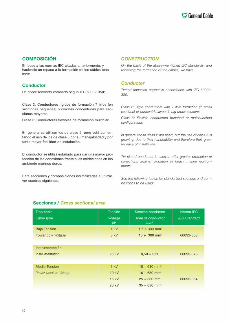
Tipo cable Tensión Sección conductor Norma IEC
Cable type Voltage Area of conductor IEC StandardkV mm2
Baja Tensión 1 kV 1,5 ÷ 300 mm2
Power Low Voltage 3 kV 10 ÷ 300 mm2 60092-353
Instrumentación
Instrumentation 250 V 0,50 ÷ 2,50 60092-376
Media Tensión 6 kV 10 ÷ 630 mm2
Power Medium Voltage 10 kV 16 ÷ 630 mm2
15 kV 25 ÷ 630 mm2 60092-354
20 kV 35 ÷ 630 mm2
Secciones / Cross sectional area
11
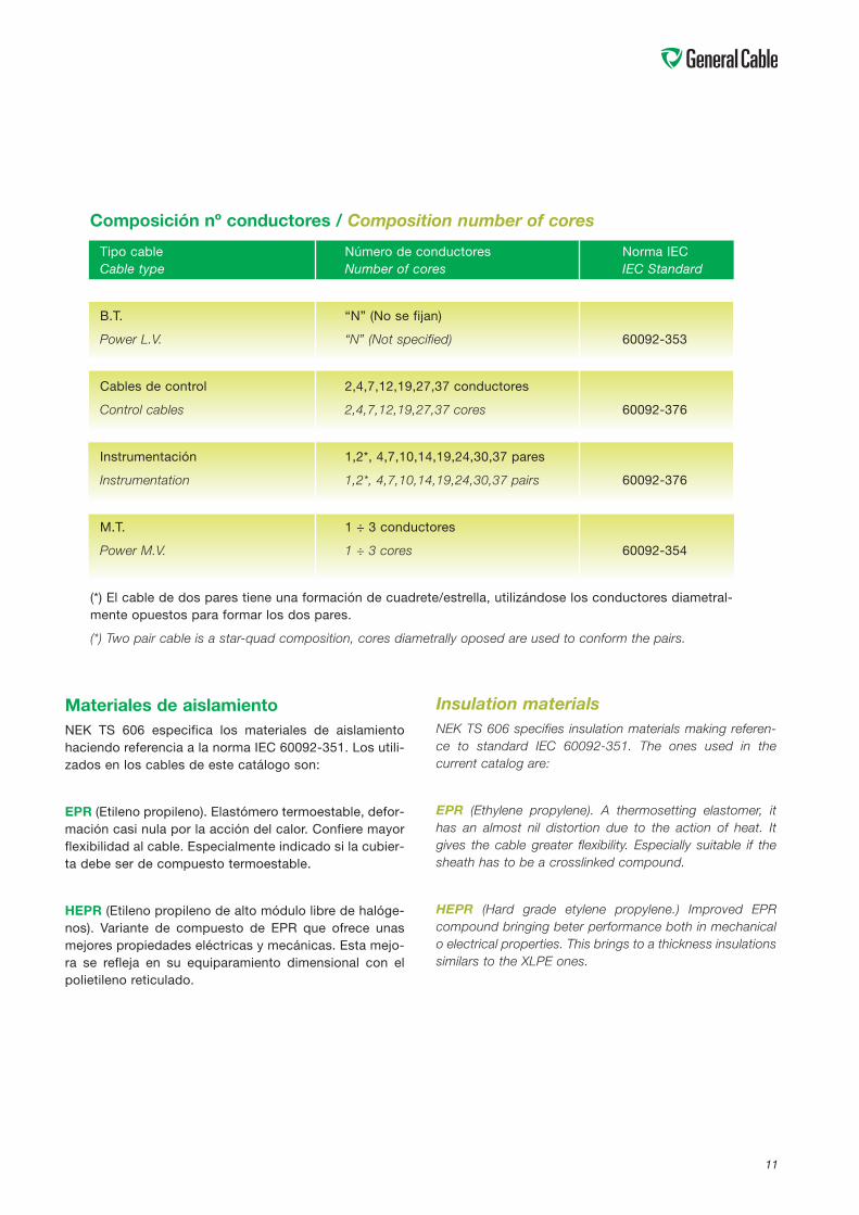
Insulation materialsNEK TS 606 specifies insulation materials making referen-ce to standard IEC 60092-351. The ones used in thecurrent catalog are:
EPR (Ethylene propylene). A thermosetting elastomer, ithas an almost nil distortion due to the action of heat. Itgives the cable greater flexibility. Especially suitable if thesheath has to be a crosslinked compound.
HEPR (Hard grade etylene propylene.) Improved EPRcompound bringing beter performance both in mechanicalo electrical properties. This brings to a thickness insulationssimilars to the XLPE ones.
Materiales de aislamientoNEK TS 606 especifica los materiales de aislamientohaciendo referencia a la norma IEC 60092-351. Los utili-zados en los cables de este catálogo son:
EPR (Etileno propileno). Elastómero termoestable, defor-mación casi nula por la acción del calor. Confiere mayorflexibilidad al cable. Especialmente indicado si la cubier-ta debe ser de compuesto termoestable.
HEPR (Etileno propileno de alto módulo libre de halóge-nos). Variante de compuesto de EPR que ofrece unasmejores propiedades eléctricas y mecánicas. Esta mejo-ra se refleja en su equiparamiento dimensional con elpolietileno reticulado.
Tipo cable Número de conductores Norma IECCable type Number of cores IEC Standard
B.T. “N” (No se fijan)
Power L.V. “N” (Not specified) 60092-353
Cables de control 2,4,7,12,19,27,37 conductores
Control cables 2,4,7,12,19,27,37 cores 60092-376
Instrumentación 1,2*, 4,7,10,14,19,24,30,37 pares
Instrumentation 1,2*, 4,7,10,14,19,24,30,37 pairs 60092-376
M.T. 1 ÷ 3 conductores
Power M.V. 1 ÷ 3 cores 60092-354
(*) El cable de dos pares tiene una formación de cuadrete/estrella, utilizándose los conductores diametral-mente opuestos para formar los dos pares.
(*) Two pair cable is a star-quad composition, cores diametrally oposed are used to conform the pairs.
Composición nº conductores / Composition number of cores
1212
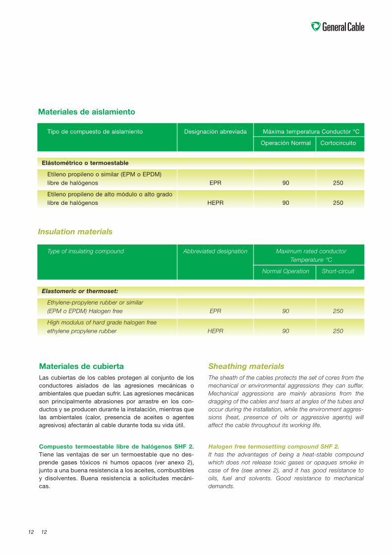
Type of insulating compound Abbreviated designation Maximum rated conductorTemperature °C
Normal Operation Short-circuit
Elastomeric or thermoset:
Ethylene-propylene rubber or similar(EPM o EPDM) Halogen free EPR 90 250
High modulus of hard grade halogen freeethylene propylene rubber HEPR 90 250
Insulation materials
Materiales de cubiertaLas cubiertas de los cables protegen al conjunto de losconductores aislados de las agresiones mecánicas oambientales que puedan sufrir. Las agresiones mecánicasson principalmente abrasiones por arrastre en los con-ductos y se producen durante la instalación, mientras quelas ambientales (calor, presencia de aceites o agentesagresivos) afectarán al cable durante toda su vida útil.
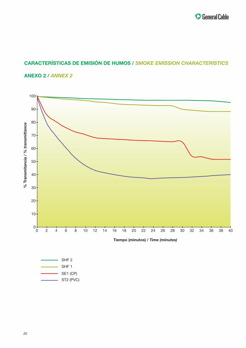
Compuesto termoestable libre de halógenos SHF 2.Tiene las ventajas de ser un termoestable que no des-prende gases tóxicos ni humos opacos (ver anexo 2),junto a una buena resistencia a los aceites, combustiblesy disolventes. Buena resistencia a solicitudes mecáni-cas.
Sheathing materialsThe sheath of the cables protects the set of cores from themechanical or environmental aggressions they can suffer.Mechanical aggressions are mainly abrasions from thedragging of the cables and tears at angles of the tubes andoccur during the installation, while the environment aggres-sions (heat, presence of oils or aggressive agents) willaffect the cable throughout its working life.
Halogen free termosetting compound SHF 2.It has the advantages of being a heat-stable compoundwhich does not release toxic gases or opaques smoke incase of fire (see annex 2), and it has good resistance tooils, fuel and solvents. Good resistance to mechanicaldemands.
Tipo de compuesto de aislamiento Designación abreviada Máxima temperatura Conductor °C
Operación Normal Cortocircuito
Elástométrico o termoestable
Etileno propileno o similar (EPM o EPDM)libre de halógenos EPR 90 250
Etileno propileno de alto módulo o alto gradolibre de halógenos HEPR 90 250
Materiales de aislamiento
13
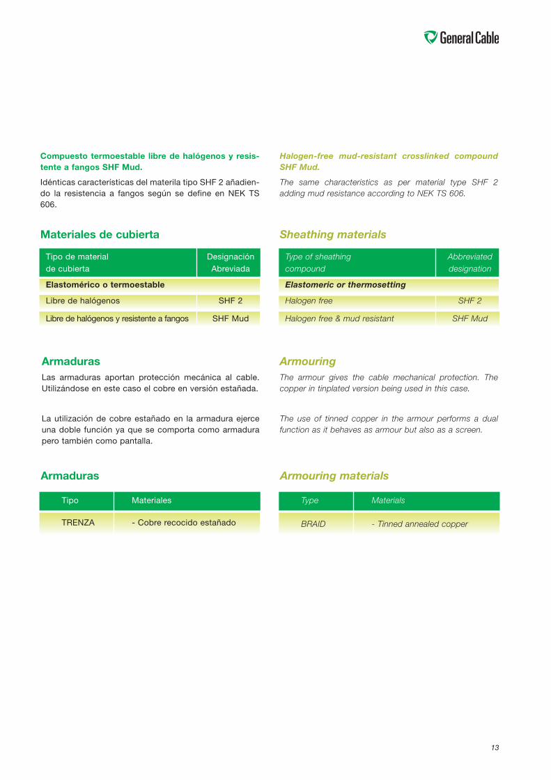
Materiales de cubierta
Tipo de material Designaciónde cubierta Abreviada
Elastomérico o termoestable
Libre de halógenos SHF 2
Libre de halógenos y resistente a fangos SHF Mud
Sheathing materials
Type of sheathing Abbreviatedcompound designation
Elastomeric or thermosetting
Halogen free SHF 2
Halogen free & mud resistant SHF Mud
ArmadurasLas armaduras aportan protección mecánica al cable.Utilizándose en este caso el cobre en versión estañada.
La utilización de cobre estañado en la armadura ejerceuna doble función ya que se comporta como armadurapero también como pantalla.
ArmouringThe armour gives the cable mechanical protection. Thecopper in tinplated version being used in this case.
The use of tinned copper in the armour performs a dualfunction as it behaves as armour but also as a screen.
Armouring materials
Type Materials
BRAID - Tinned annealed copper
Armaduras
Tipo Materiales
TRENZA - Cobre recocido estañado
Compuesto termoestable libre de halógenos y resis-tente a fangos SHF Mud.
Idénticas características del materila tipo SHF 2 añadien-do la resistencia a fangos según se define en NEK TS606.
Halogen-free mud-resistant crosslinked compoundSHF Mud.
The same characteristics as per material type SHF 2adding mud resistance according to NEK TS 606.
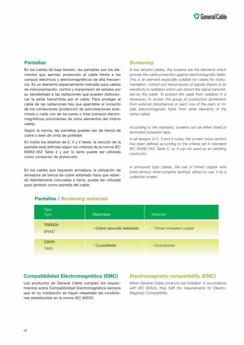
PantallasEn los cables de baja tensión, las pantallas son los ele-mentos que aportan protección al cable frente a loscampos eléctricos y electromagnéticos de alta frecuen-cia. Es un elemento especialmente indicado para cablesde instrumentación, control y transmisión de señales porsu sensibilidad a las radiaciones que pueden distorsio-nar la señal transmitida por el cable. Para proteger elcable de las radiaciones hay que apantallar el conjuntode los conductores (protección de perturbaciones exte-riores) o cada uno de los pares o tríos (campos electro-magnéticos provinientes de otros elementos del mismocable).
Según la norma, las pantallas pueden ser de trenza decobre o bien de cinta de poliéster.
En todos los diseños de 2, 3 y 4 fases, la sección de lapantalla está definida según los criterios de la norma IEC60092-352 Table 2 y por lo tanto puede ser utilizadacomo conductor de protección.
En los cables que requieren armadura, la utilización dearmadura de trenza de cobre estañado hace que estan-do debidamente colocadas a tierra, pueda ser utilizadapara también como pantalla del cable.
ScreeningIn low tensión cables, the screens are the elements whichprovide the cable protection against electromagnetic fields.This is an element especially suitable for cables for instru-mentation, control and transmission of signals thanks to itssensitivity to radiation which can distort the signal transmit-ted by the cable. To protect the cable from radiation it isnecessary to screen the group of conductors (protectionfrom external disturbance) or each one of the pairs or tri-ples (electromagnetic fields from other elements of thesame cable).
According to the standard, screens can be either braid orlaminated polyester tape.
In all designs of 2, 3 and 4 cores, the screen cross-sectionhas been defined according to the criteria set in standardIEC 60092-352 Table 2, so it can be used as an earthingconductor.
In armoured type cables, the use of tinned copper wirebraid armour, when properly earthed, allows to use it as acollective screen.
Pantallas / Screening materials
TipoType Materiales Materials
TRENZA
BRAID- Cobre recocido estañado - Tinned annealed copper
CINTA
TAPE- Cu/poliéster - Cu/polyester
14
Compatibilidad Electromagnética (EMC)Los productos de General Cable cumplen los requeri-mientos sobre Compatibilidad Electromagnética siempreque en su instalación se hayan respetado las condicio-nes establecidas en la norma IEC 60533.
Electromagnetic compatibility (EMC)When General Cable products are installed in accordancewith IEC 60533, they fulfil the requirements for Electro-Magnetic Compatibility.
15
COMPORTAMIENTO DE LOS CABLESEN CASO DE FUEGOA fin de determinar el comportamiento de los cablesante una situación de incendio, se han desarrollado unaserie de normas que definen unas condiciones de fuegoy miden el comportamiento del cable en una situaciónsimilar a la de instalación, sin embargo, debe tenerse encuenta que estos ensayos establecen unas condicionesfijas y reproducibles y sirven para valorar el comporta-miento de los cables en dicha situación.
La normativa IEC actual contempla los siguientes casos:
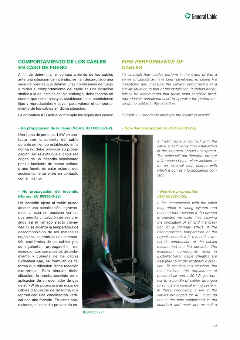
- No propagación de la llama (Norma IEC 60332-1-2).
Una llama de potencia 1 kW en con-tacto con la cubierta del cabledurante un tiempo establecido en lanorma no debe provocar su propa-gación. Así se evita que el cable seaorigen de un incendio ocasionadopor un incidente de menor entidado una fuente de calor externa queaccidentalmente entre en contactocon el mismo.
- No propagación del incendio(Norma IEC 60332-3-22)
Un incendio ajeno al cable puedeafectar una canalización, agraván-dose si está en posición verticalque permita circulación de aire cre-ando así el llamado efecto chime-nea. Si se alcanza la temperatura dedescomposición de los materialesorgánicos, se produce una combus-tión exotérmica de los cables y laconsiguiente propagación delincendio. Los compuestos de aisla-miento y cubierta de los cablesExzhellent-Mar, se formulan de talforma que dificulten dicha reacciónexotérmica. Para simular dichasituación, la prueba consiste en laaplicación de un quemador de gasde 20 kW de potencia a un mazo decables dispuestos de tal forma quereproducen una canalización verti-cal con aire forzado. En estas con-diciones, el incendio provocado en
FIRE PERFORMANCE OFCABLESTo establish how cables perform in the event of fire, aseries of standards have been developed to define fireconditions and measure the cable’s performance in asimilar situation to that of the installation. It should nonet-heless be remembered that these tests establish fixed,reproducible conditions used to appraise the performan-ce of the cables in this situation.
Current IEC standards envisage the following events:
- Non-flame propagation (IEC 60332-1-2).
A 1-kW flame in contact with thecable sheath for a time establishedin the standard should not spread.The cable will not therefore prompta fire caused by a minor incident orby an external heat source withwhich it comes into accidental con-tact.
- Non-fire propagation(IEC 60332-3-22)
A fire unconnected with the cablemay affect a wiring system andbecome more serious if the systemis oriented vertically, thus allowingthe circulation of air and the crea-tion of a chimney effect. If thedecomposition temperature of theorganic materials is reached, exot-hermic combustion of the cablesoccurs and the fire spreads. Theinsulation compounds used inExzhellent-Mar cable sheaths aredesigned to hinder exothermic reac-tion. To simulate this situation, thetest involves the application ofpowered air and a 20-kW gas bur-ner to a bundle of cables arrangedto simulate a vertical wiring system.In these conditions, a fire in thecables prolonged for 40’ must goout in the time established in thestandard and must not exceed a
IEC 60332-1
16
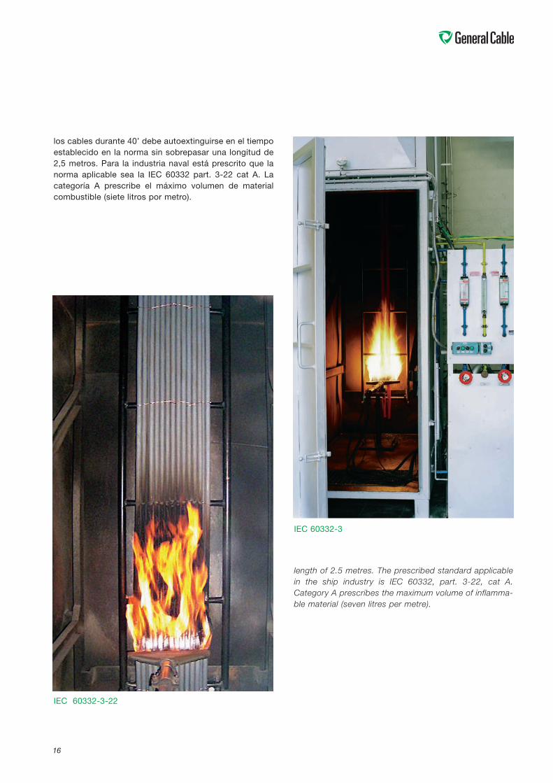
los cables durante 40’ debe autoextinguirse en el tiempoestablecido en la norma sin sobrepasar una longitud de2,5 metros. Para la industria naval está prescrito que lanorma aplicable sea la IEC 60332 part. 3-22 cat A. Lacategoría A prescribe el máximo volumen de materialcombustible (siete litros por metro).
length of 2.5 metres. The prescribed standard applicablein the ship industry is IEC 60332, part. 3-22, cat A.Category A prescribes the maximum volume of inflamma-ble material (seven litres per metre).
IEC 60332-3-22
IEC 60332-3
17
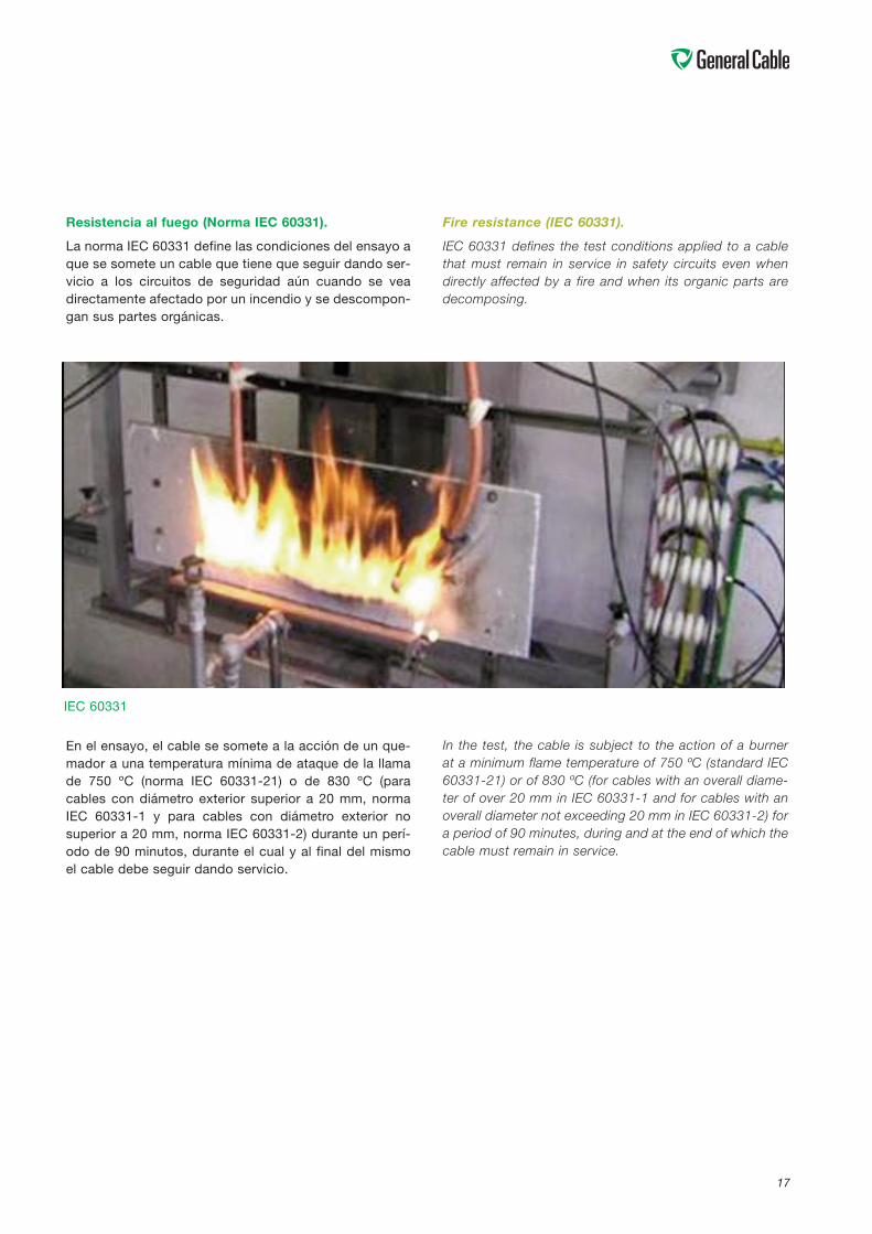
Resistencia al fuego (Norma IEC 60331).
La norma IEC 60331 define las condiciones del ensayo aque se somete un cable que tiene que seguir dando ser-vicio a los circuitos de seguridad aún cuando se veadirectamente afectado por un incendio y se descompon-gan sus partes orgánicas.
En el ensayo, el cable se somete a la acción de un que-mador a una temperatura mínima de ataque de la llamade 750 ºC (norma IEC 60331-21) o de 830 ºC (paracables con diámetro exterior superior a 20 mm, normaIEC 60331-1 y para cables con diámetro exterior nosuperior a 20 mm, norma IEC 60331-2) durante un perí-odo de 90 minutos, durante el cual y al final del mismoel cable debe seguir dando servicio.
Fire resistance (IEC 60331).
IEC 60331 defines the test conditions applied to a cablethat must remain in service in safety circuits even whendirectly affected by a fire and when its organic parts aredecomposing.
In the test, the cable is subject to the action of a burnerat a minimum flame temperature of 750 ºC (standard IEC60331-21) or of 830 ºC (for cables with an overall diame-ter of over 20 mm in IEC 60331-1 and for cables with anoverall diameter not exceeding 20 mm in IEC 60331-2) fora period of 90 minutes, during and at the end of which thecable must remain in service.
IEC 60331
18
IEC 60754
IEC 61034
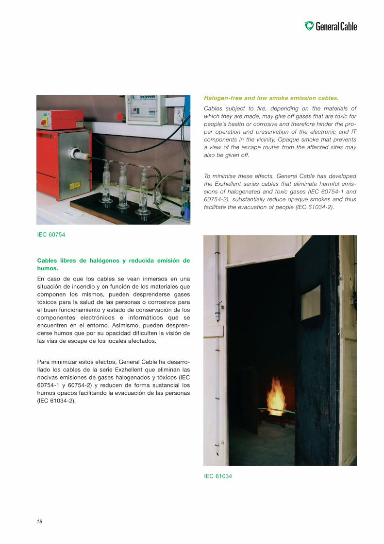
Cables libres de halógenos y reducida emisión dehumos.
En caso de que los cables se vean inmersos en unasituación de incendio y en función de los materiales quecomponen los mismos, pueden desprenderse gasestóxicos para la salud de las personas o corrosivos parael buen funcionamiento y estado de conservación de loscomponentes electrónicos e informáticos que seencuentren en el entorno. Asimismo, pueden despren-derse humos que por su opacidad dificulten la visión delas vías de escape de los locales afectados.
Para minimizar estos efectos, General Cable ha desarro-llado los cables de la serie Exzhellent que eliminan lasnocivas emisiones de gases halogenados y tóxicos (IEC60754-1 y 60754-2) y reducen de forma sustancial loshumos opacos facilitando la evacuación de las personas(IEC 61034-2).
Halogen-free and low smoke emission cables.
Cables subject to fire, depending on the materials ofwhich they are made, may give off gases that are toxic forpeople’s health or corrosive and therefore hinder the pro-per operation and preservation of the electronic and ITcomponents in the vicinity. Opaque smoke that preventsa view of the escape routes from the affected sites mayalso be given off.
To minimise these effects, General Cable has developedthe Exzhellent series cables that eliminate harmful emis-sions of halogenated and toxic gases (IEC 60754-1 and60754-2), substantially reduce opaque smokes and thusfacilitate the evacuation of people (IEC 61034-2).
19
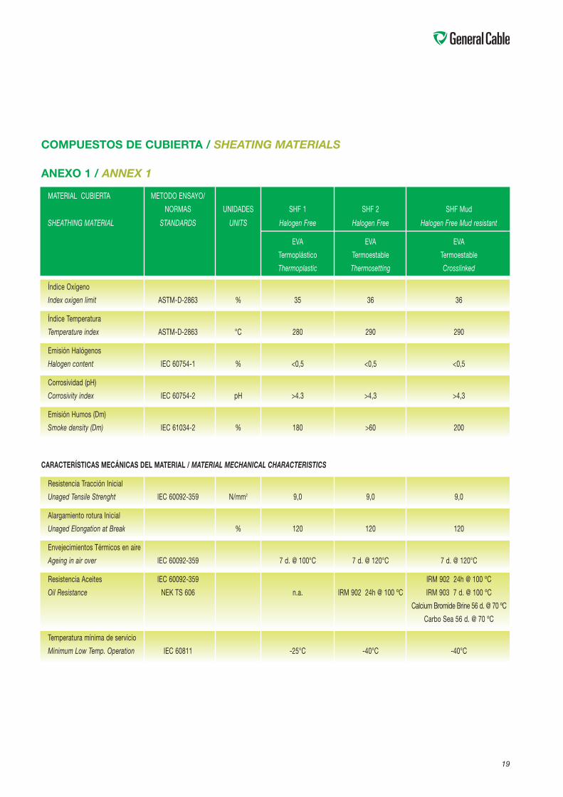
MATERIAL CUBIERTA METODO ENSAYO/
NORMAS UNIDADES SHF 1 SHF 2 SHF Mud
SHEATHING MATERIAL STANDARDS UNITS Halogen Free Halogen Free Halogen Free Mud resistant
EVA EVA EVA
Termoplástico Termoestable Termoestable
Thermoplastic Thermosetting Crosslinked
Índice Oxígeno
Index oxigen limit ASTM-D-2863 % 35 36 36
Índice Temperatura
Temperature index ASTM-D-2863 °C 280 290 290
Emisión Halógenos
Halogen content IEC 60754-1 % <0,5 <0,5 <0,5
Corrosividad (pH)
Corrosivity index IEC 60754-2 pH >4.3 >4,3 >4,3
Emisión Humos (Dm)
Smoke density (Dm) IEC 61034-2 % 180 >60 200
CARACTERÍSTICAS MECÁNICAS DEL MATERIAL / MATERIAL MECHANICAL CHARACTERISTICS
Resistencia Tracción Inicial
Unaged Tensile Strenght IEC 60092-359 N/mm2 9,0 9,0 9,0
Alargamiento rotura Inicial
Unaged Elongation at Break % 120 120 120
Envejecimientos Térmicos en aire
Ageing in air over IEC 60092-359 7 d. @ 100°C 7 d. @ 120°C 7 d. @ 120°C
Resistencia Aceites IEC 60092-359 IRM 902 24h @ 100 ºC
Oil Resistance NEK TS 606 n.a. IRM 902 24h @ 100 ºC IRM 903 7 d. @ 100 ºC
Calcium Bromide Brine 56 d. @ 70 ºC
Carbo Sea 56 d. @ 70 ºC
Temperatura mínima de servicio
Minimum Low Temp. Operation IEC 60811 -25°C -40°C -40°C
COMPUESTOS DE CUBIERTA / SHEATING MATERIALS
ANEXO 1 / ANNEX 1
20
CARACTERÍSTICAS DE EMISIÓN DE HUMOS / SMOKE EMISSION CHARACTERISTICS
ANEXO 2 / ANNEX 2
00
2
ST2 (PVC)
Tiempo (minutos) / Time (minutes)
%Tr
ansm
itan
cia
/%
tran
smit
tan
ce
4 6 8 10 12 14 16 18 20 22 24 26 28 30 32 34 36 38 40
10
20
30
40
50
60
70
80
90
100
SE1 (CP)
SHF 1
SHF 2
21
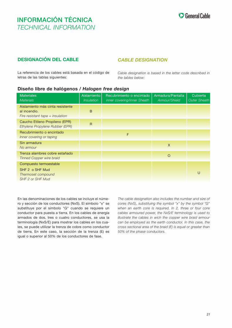
INFORMACIÓN TÉCNICATECHNICAL INFORMATION
DESIGNACIÓN DEL CABLE
La referencia de los cables está basada en el código deletras de las tablas siguientes:
CABLE DESIGNATION
Cable designation is based in the letter code described inthe tables below:
Diseño libre de halógenos / Halogen free designMateriales Aislamiento Recubrimiento o encintado Armadura/Pantalla CubiertaMaterials Insulation inner covering/inner Sheath Armour/Shield Outer Sheath
Aislamiento más cinta resistenteal incendio.Fire resistant tape + insulation
B
Caucho Etileno Propileno (EPR)Ethylene Propylene Rubber (EPR)
R
Recubrimiento o encintadoInner covering or taping
F
Sin armaduraNo armour
X
Trenza alambres cobre estañadoTinned Copper wire braid
O
Compuesto termoestable
SHF 2 o SHF MudThermoset compound U
SHF 2 or SHF Mud
En las denominaciones de los cables se incluye el núme-ro y sección de los conductores (NxS). El símbolo "x" sesubstituye por el símbolo "G" cuando se requiere unconductor para puesta a tierra. En los cables de energíaarmados de dos, tres o cuatro conductores, se usa laterminología (NxS/E) para mostrar los cables en los cua-les, se puede utilizar la trenza de cobre como conductorde tierra. En este caso, la sección de la trenza (E) esigual o superior al 50% de los conductores de fase.
The cable designation also includes the number and size ofcores (NxS), substituing the symbol "x" by the symbol "G"when an earth core is required. In 2, three or four corecables armoured power, the NxS/E terminology is used toillustrate the cables in wich the copper wire braid armourcan be employed as the earth conductor. In this case, thecross sectional area of the braid (E) is equal or greater than50% of the phase conductors.
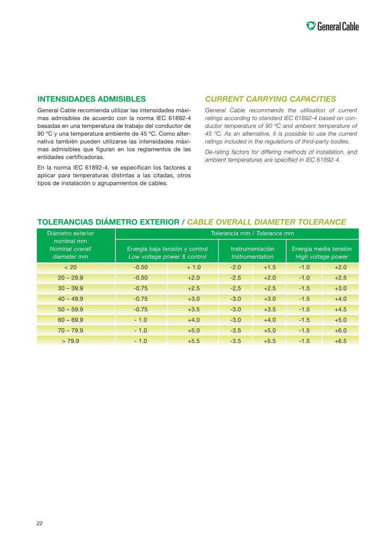
22
TOLERANCIAS DIÁMETRO EXTERIOR / CABLE OVERALL DIAMETER TOLERANCEDiámetro exterior Tolerancia mm / Tolerance mm
nominal mmNominal overall Energía baja tensión y control Instrumentación Energía media tensióndiameter mm Low voltage power & control Instrumentation High voltage power
< 20 -0.50 + 1.0 -2.0 +1.5 -1.0 +2.0
20 – 29.9 -0.50 +2.0 -2.5 +2.0 -1.0 +2.5
30 – 39.9 -0.75 +2.5 -2,5 +2.5 -1.5 +3.0
40 – 49.9 -0.75 +3.0 -3.0 +3.0 -1.5 +4.0
50 – 59.9 -0.75 +3.5 -3.0 +3.5 -1.5 +4.5
60 – 69.9 - 1.0 +4.0 -3.0 +4.0 -1.5 +5.0
70 – 79.9 - 1.0 +5.0 -3.5 +5.0 -1.5 +6.0
> 79.9 - 1.0 +5.5 -3.5 +5.5 -1.5 +6.5
INTENSIDADES ADMISIBLESGeneral Cable recomienda utilizar las intensidades máxi-mas admisibles de acuerdo con la norma IEC 61892-4basadas en una temperatura de trabajo del conductor de90 ºC y una temperatura ambiente de 45 ºC. Como alter-nativa también pueden utilizarse las intensidades máxi-mas admisibles que figuran en los reglamentos de lasentidades certificadoras.
En la norma IEC 61892-4, se especifican los factores aaplicar para temperaturas distintas a las citadas, otrostipos de instalación o agrupamientos de cables.
CURRENT CARRYING CAPACITIESGeneral Cable recommends the utilisation of currentratings according to standard IEC 61892-4 based on con-ductor temperature of 90 ºC and ambient temperature of45 ºC. As an alternative, it is possible to use the currentratings included in the regulations of third-party bodies.
De-rating factors for differing methods of installation, andambient temperatures are specified in IEC 61892-4.
23
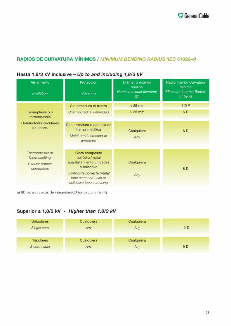
Superior a 1,8/3 kV - Higher than 1,8/3 kV
Unipolares
Single core
Tripolares
3 core cable
Cualquiera
Any
Cualquiera
Any
Cualquiera
Any
Cualquiera
Any
12 D
9 D
RADIOS DE CURVATURA MÍNIMOS / MINIMUM BENDING RADIUS (IEC 61892-4)
Hasta 1,8/3 kV inclusive – Up to and including 1,8/3 kV
Aislamiento
Insulation
Termoplástico otermoestable
Conductores circularesde cobre.
Thermoplastic orThermosetting.
Circular copperconductors
Protección
Covering
Sin armadura ni trenza
Unarmoured or unbraided
Con armadura o pantalla detrenza metálica
Metal braid screened orarmoured
Cinta compositepoliéster/metal
apantallamiento unidadeso colectivo
Composite polyester/metaltape screened units or
collective tape screening
Diámetro exteriornominal
Nominal overall diameter(D)
< 25 mm
> 25 mm
Cualquiera
Any
Cualquiera
Any
Radio Interior Curvaturamínimo
Minimum internal Radiusof bend
4 D a
6 D
6 D
8 D
a) 6D para circuitos de integridad/6D for circuit integrity
24
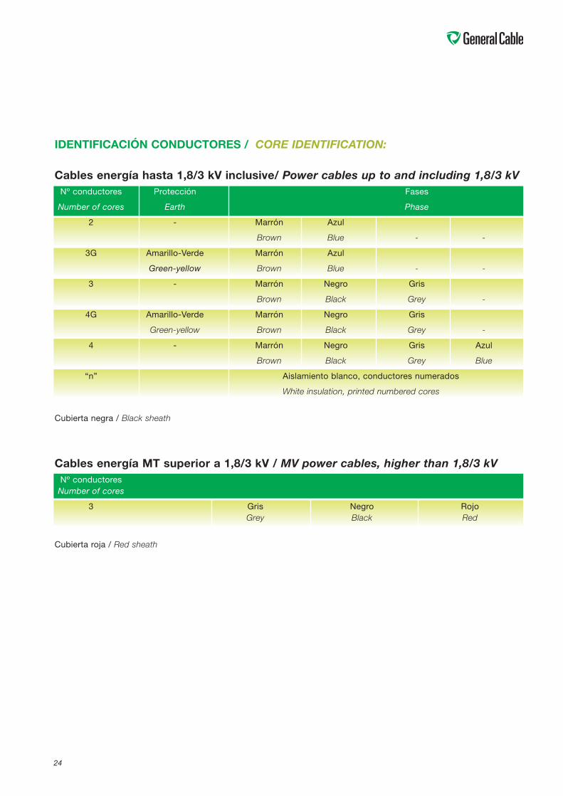
IDENTIFICACIÓN CONDUCTORES / CORE IDENTIFICATION:
Cables energía hasta 1,8/3 kV inclusive/ Power cables up to and including 1,8/3 kVNº conductores Protección Fases
Number of cores Earth Phase
2 - Marrón Azul
Brown Blue - -
3G Amarillo-Verde Marrón Azul
Green-yellow Brown Blue - -
3 - Marrón Negro Gris
Brown Black Grey -
4G Amarillo-Verde Marrón Negro Gris
Green-yellow Brown Black Grey -
4 - Marrón Negro Gris Azul
Brown Black Grey Blue
“n” Aislamiento blanco, conductores numerados
White insulation, printed numbered cores
Cubierta negra / Black sheath
Cables energía MT superior a 1,8/3 kV / MV power cables, higher than 1,8/3 kVNº conductoresNumber of cores
3 Gris Negro RojoGrey Black Red
Cubierta roja / Red sheath
25
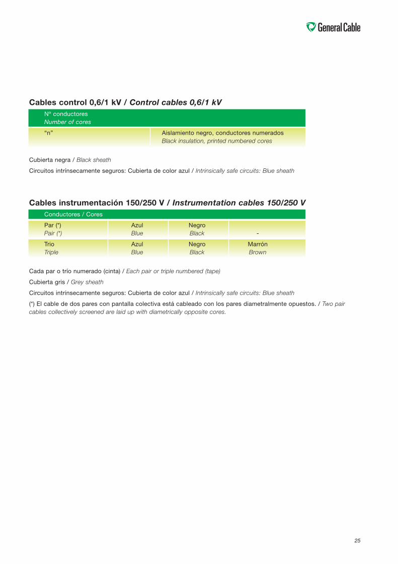
Cables control 0,6/1 kV / Control cables 0,6/1 kVNº conductoresNumber of cores
“n” Aislamiento negro, conductores numeradosBlack insulation, printed numbered cores
Cubierta negra / Black sheath
Circuitos intrínsecamente seguros: Cubierta de color azul / Intrinsically safe circuits: Blue sheath
Cables instrumentación 150/250 V / Instrumentation cables 150/250 VConductores / Cores
Par (*) Azul NegroPair (*) Blue Black -
Trio Azul Negro MarrónTriple Blue Black Brown
Cada par o trío numerado (cinta) / Each pair or triple numbered (tape)
Cubierta gris / Grey sheath
Circuitos intrínsecamente seguros: Cubierta de color azul / Intrinsically safe circuits: Blue sheath
(*) El cable de dos pares con pantalla colectiva está cableado con los pares diametralmente opuestos. / Two paircables collectively screened are laid up with diametrically opposite cores.
26
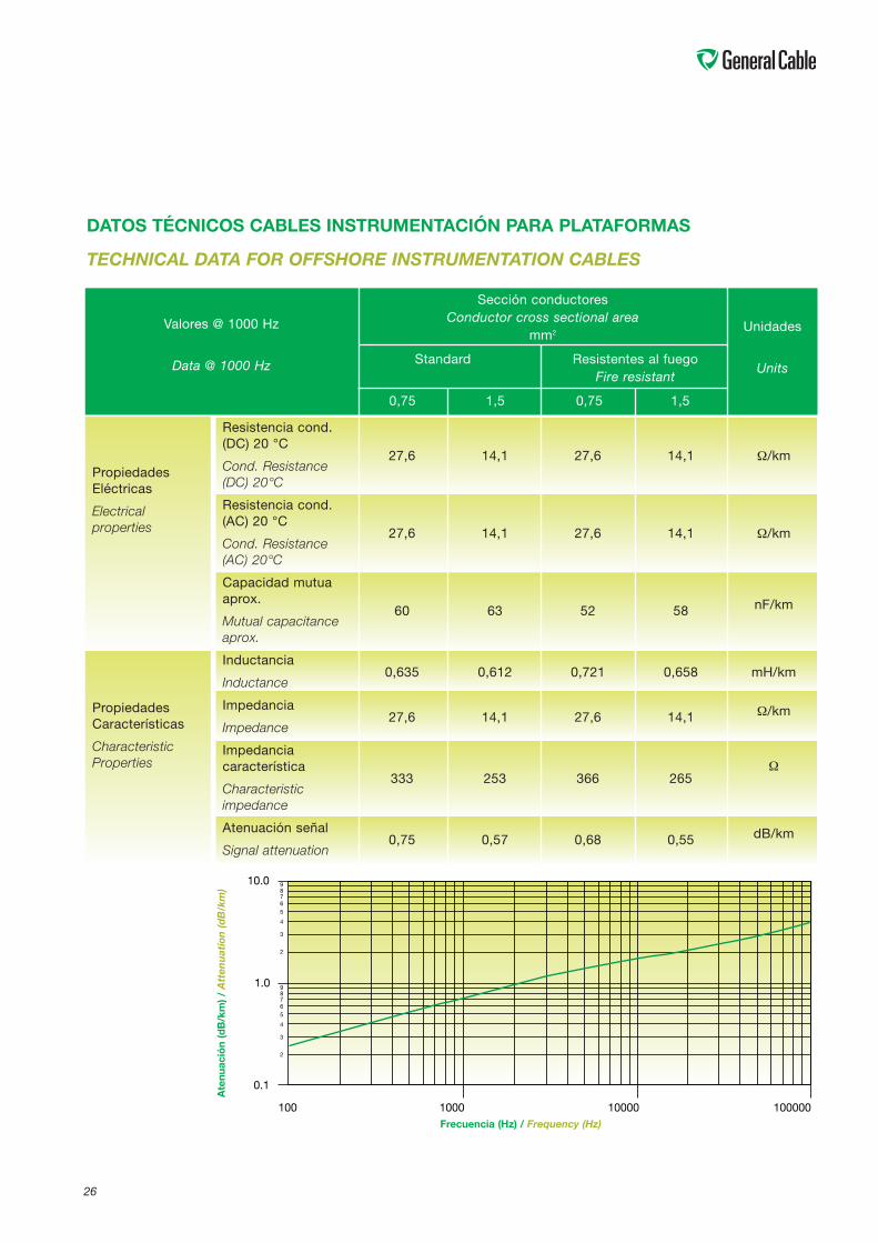
DATOS TÉCNICOS CABLES INSTRUMENTACIÓN PARA PLATAFORMAS
TECHNICAL DATA FOR OFFSHORE INSTRUMENTATION CABLES
PropiedadesEléctricas
Electricalproperties
PropiedadesCaracterísticas
CharacteristicProperties
Resistencia cond.(DC) 20 °C
Cond. Resistance(DC) 20°C
Resistencia cond.(AC) 20 °C
Cond. Resistance(AC) 20°C
Capacidad mutuaaprox.
Mutual capacitanceaprox.
Inductancia
Inductance
Impedancia
Impedance
Impedanciacaracterística
Characteristicimpedance
Atenuación señal
Signal attenuation
27,6
27,6
60
0,635
27,6
333
0,75
14,1
14,1
63
0,612
14,1
253
0,57
27,6
27,6
52
0,721
27,6
366
0,68
14,1
14,1
58
0,658
14,1
265
0,55
Ω/km
Ω/km
nF/km
mH/km
Ω/km
Ω
dB/km
Sección conductoresConductor cross sectional area
mm2
Standard Resistentes al fuegoFire resistant
0,75 1,5 0,75 1,5
100000100001000100
0.1
2
3
4
56789
2
3
4
5678910.0
1.0
1
Frecuencia (Hz) / Frequency (Hz)
Atenuación(dB/km)/Att
enuat
ion
(dB
/km
)
Unidades
Units
Valores @ 1000 Hz
Data @ 1000 Hz
27
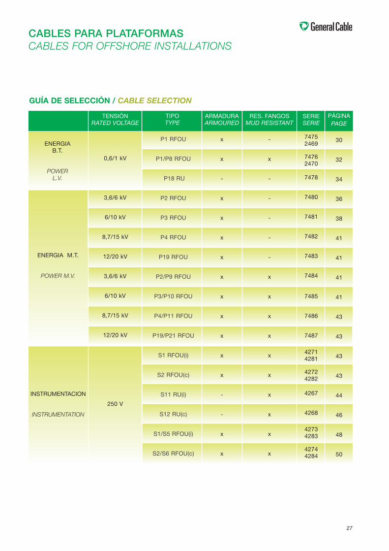
CABLES PARA PLATAFORMASCABLES FOR OFFSHORE INSTALLATIONS
TENSIÓNRATED VOLTAGE
0,6/1 kV
3,6/6 kV
6/10 kV
8,7/15 kV
12/20 kV
3,6/6 kV
6/10 kV
8,7/15 kV
12/20 kV
250 V
TIPOTYPE
P1 RFOU
P1/P8 RFOU
P18 RU
P2 RFOU
P3 RFOU
P4 RFOU
P19 RFOU
P2/P9 RFOU
P3/P10 RFOU
P4/P11 RFOU
P19/P21 RFOU
S1 RFOU(i)
S2 RFOU(c)
S11 RU(i)
S12 RU(c)
S1/S5 RFOU(i)
S2/S6 RFOU(c)
ARMADURAARMOURED
x
x
-
x
x
x
x
x
x
x
x
x
x
-
-
x
x
SERIESERIE
74752469
74762470
7478
7480
7481
7482
7483
7484
7485
7486
7487
42714281
42724282
4267
4268
42734283
42744284
PÁGINAPAGE
30
32
34
36
38
41
41
41
41
43
43
43
43
44
46
48
50
GUÍA DE SELECCIÓN / CABLE SELECTION
RES. FANGOSMUD RESISTANT
-
x
-
-
-
-
-
x
x
x
x
x
x
x
x
x
x
ENERGIAB.T.
POWERL.V.
ENERGIA M.T.
POWER M.V.
INSTRUMENTACION
INSTRUMENTATION
28
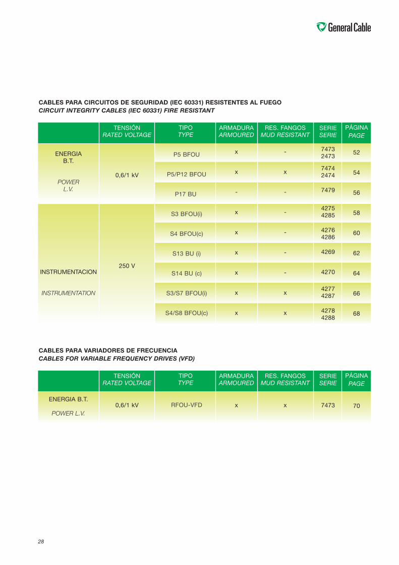
CABLES PARA CIRCUITOS DE SEGURIDAD (IEC 60331) RESISTENTES AL FUEGOCIRCUIT INTEGRITY CABLES (IEC 60331) FIRE RESISTANT
TENSIÓNRATED VOLTAGE
0,6/1 kV
250 V
TIPOTYPE
P5 BFOU
P5/P12 BFOU
P17 BU
S3 BFOU(i)
S4 BFOU(c)
S13 BU (i)
S14 BU (c)
S3/S7 BFOU(i)
S4/S8 BFOU(c)
ARMADURAARMOURED
x
x
-
x
x
x
x
x
x
SERIESERIE
74732473
74742474
7479
42754285
42764286
4269
4270
42774287
42784288
PÁGINAPAGE
52
54
56
58
60
62
64
66
68
RES. FANGOSMUD RESISTANT
-
x
-
-
-
-
-
x
x
ENERGIAB.T.
POWERL.V.
INSTRUMENTACION
INSTRUMENTATION
CABLES PARA VARIADORES DE FRECUENCIACABLES FOR VARIABLE FREQUENCY DRIVES (VFD)
TENSIÓNRATED VOLTAGE
0,6/1 kV
TIPOTYPE
RFOU-VFD
ARMADURAARMOURED
x
SERIESERIE
7473
PÁGINAPAGE
70
RES. FANGOSMUD RESISTANT
xENERGIA B.T.
POWER L.V.

29
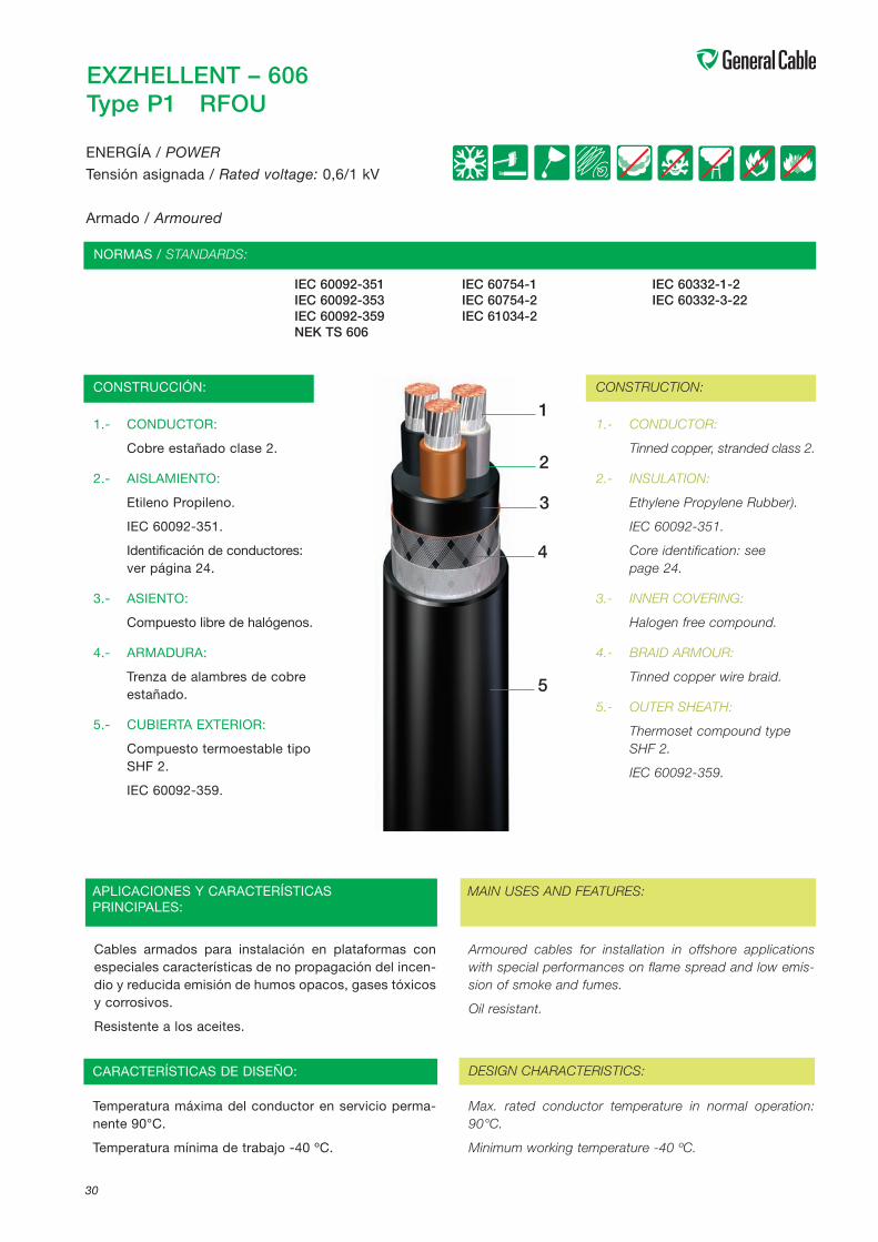
EXZHELLENT – 606Type P1 RFOU
IEC 60092-351 IEC 60754-1 IEC 60332-1-2IEC 60092-353 IEC 60754-2 IEC 60332-3-22IEC 60092-359 IEC 61034-2NEK TS 606
1.- CONDUCTOR:
Cobre estañado clase 2.
2.- AISLAMIENTO:
Etileno Propileno.
IEC 60092-351.
Identificación de conductores:ver página 24.
3.- ASIENTO:
Compuesto libre de halógenos.
4.- ARMADURA:
Trenza de alambres de cobreestañado.
5.- CUBIERTA EXTERIOR:
Compuesto termoestable tipoSHF 2.
IEC 60092-359.
1.- CONDUCTOR:
Tinned copper, stranded class 2.
2.- INSULATION:
Ethylene Propylene Rubber).
IEC 60092-351.
Core identification: seepage 24.
3.- INNER COVERING:
Halogen free compound.
4.- BRAID ARMOUR:
Tinned copper wire braid.
5.- OUTER SHEATH:
Thermoset compound typeSHF 2.
IEC 60092-359.
Armoured cables for installation in offshore applicationswith special performances on flame spread and low emis-sion of smoke and fumes.
Oil resistant.
30
ENERGÍA / POWER
Tensión asignada / Rated voltage: 0,6/1 kV
Armado / Armoured
CONSTRUCCIÓN: CONSTRUCTION:
NORMAS / STANDARDS:
MAIN USES AND FEATURES:
Cables armados para instalación en plataformas conespeciales características de no propagación del incen-dio y reducida emisión de humos opacos, gases tóxicosy corrosivos.
Resistente a los aceites.
APLICACIONES Y CARACTERÍSTICASPRINCIPALES:
CARACTERÍSTICAS DE DISEÑO: DESIGN CHARACTERISTICS:
Temperatura máxima del conductor en servicio perma-nente 90°C.
Temperatura mínima de trabajo -40 ºC.
Max. rated conductor temperature in normal operation:90°C.
Minimum working temperature -40 ºC.
1
2
3
4
5