Central Battery System Typ CPS 220/64/SV - INOTEC · Central Battery Emergency Lighting Systems ......
24
Central Battery System Typ CPS 220/64/SV Sicherheitstechnik GmbH Catalogue CPS 220/64
Transcript of Central Battery System Typ CPS 220/64/SV - INOTEC · Central Battery Emergency Lighting Systems ......
Central Battery System
Typ CPS 220/64/SV
Sicherheitstechnik GmbH
CatalogueCPS 220/64
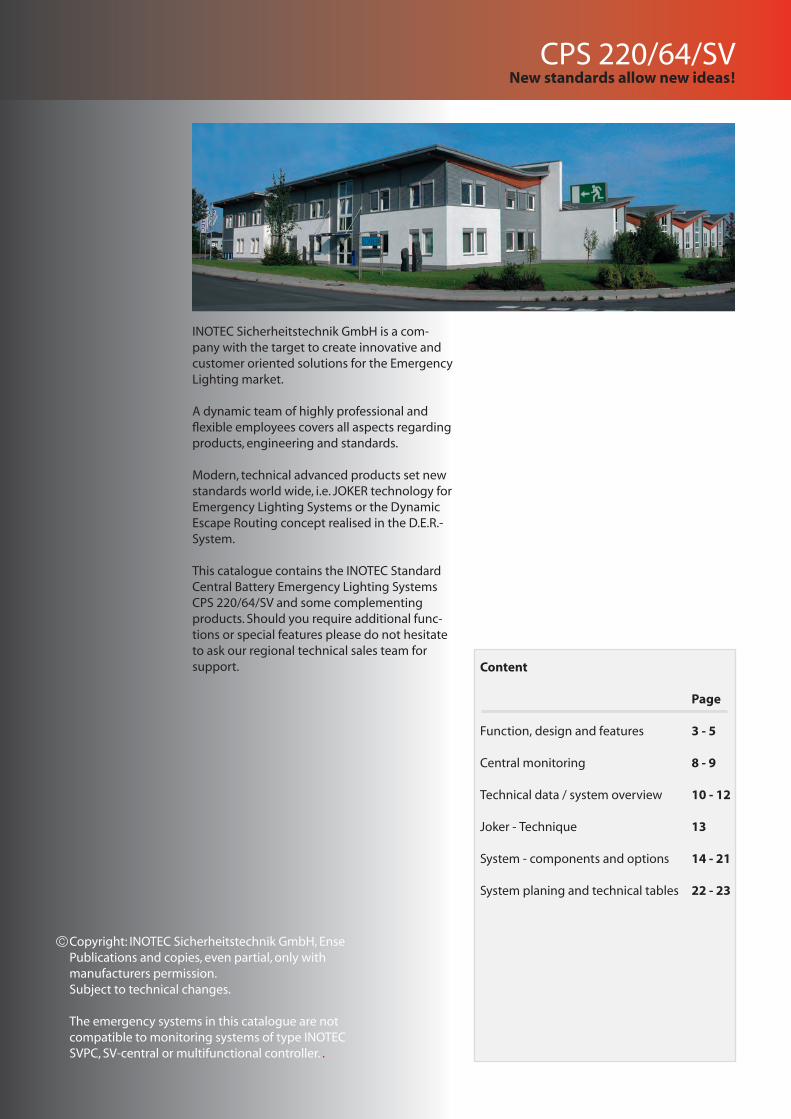
INOTEC Sicherheitstechnik GmbH is a com-pany with the target to create innovative and customer oriented solutions for the Emergency Lighting market.
A dynamic team of highly professional and flexible employees covers all aspects regarding products, engineering and standards.
Modern, technical advanced products set new standards world wide, i.e. JOKER technology for Emergency Lighting Systems or the Dynamic Escape Routing concept realised in the D.E.R.-System.
This catalogue contains the INOTEC Standard Central Battery Emergency Lighting Systems CPS 220/64/SV and some complementing products. Should you require additional func-tions or special features please do not hesitate to ask our regional technical sales team for support.
New standards allow new ideas!
Copyright: INOTEC Sicherheitstechnik GmbH, EnsePublications and copies, even partial, only with manufacturers permission.Subject to technical changes.
The emergency systems in this catalogue are not compatible to monitoring systems of type INOTEC SVPC, SV-central or multifunctional controller. .
Content
Page
Function, design and features 3 - 5
Central monitoring 8 - 9
Technical data / system overview 10 - 12
Joker - Technique 13
System - components and options 14 - 21
System planing and technical tables 22 - 23
CPS 220/64/SV
CPS 220/64/SV
3
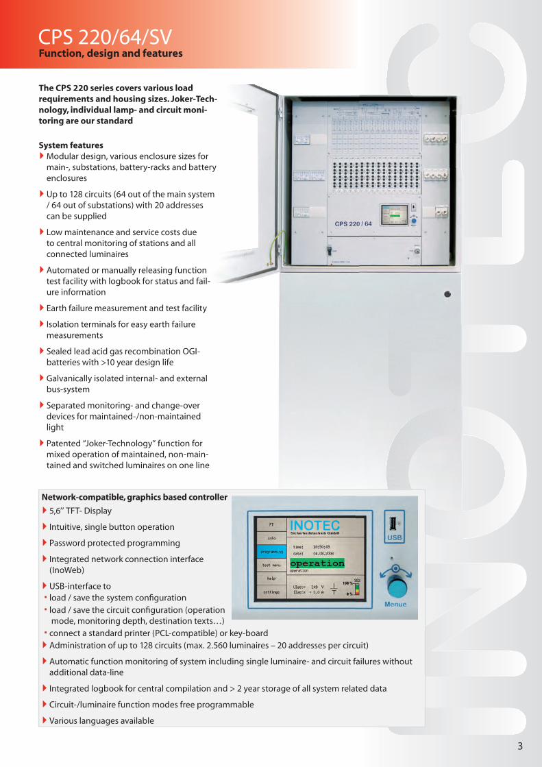
Network-compatible, graphics based controller
` 5,6’’ TFT- Display
` Intuitive, single button operation
` Password protected programming
` Integrated network connection interface (InoWeb)
` USB-interface to load / save the system confi guration load / save the circuit confi guration (operation mode, monitoring depth, destination texts…)
connect a standard printer (PCL-compatible) or key-board ` Administration of up to 128 circuits (max. 2.560 luminaires – 20 addresses per circuit)
` Automatic function monitoring of system including single luminaire- and circuit failures without additional data-line
` Integrated logbook for central compilation and > 2 year storage of all system related data
` Circuit-/luminaire function modes free programmable
` Various languages available
Function, design and features
The CPS 220 series covers various load requirements and housing sizes. Joker-Tech-nology, individual lamp- and circuit moni-toring are our standard
System features `Modular design, various enclosure sizes for main-, substations, battery-racks and battery enclosures
` Up to 128 circuits (64 out of the main system / 64 out of substations) with 20 addresses can be supplied
` Low maintenance and service costs due to central monitoring of stations and all connected luminaires
` Automated or manually releasing function test facility with logbook for status and fail-ure information
` Earth failure measurement and test facility
` Isolation terminals for easy earth failure measurements
` Sealed lead acid gas recombination OGI-batteries with >10 year design life
` Galvanically isolated internal- and external bus-system
` Separated monitoring- and change-over devices for maintained-/non-maintained light
` Patented “Joker-Technology” function for mixed operation of maintained, non-main-tained and switched luminaires on one line
4
CPS 220/64/SVFunction, design and features
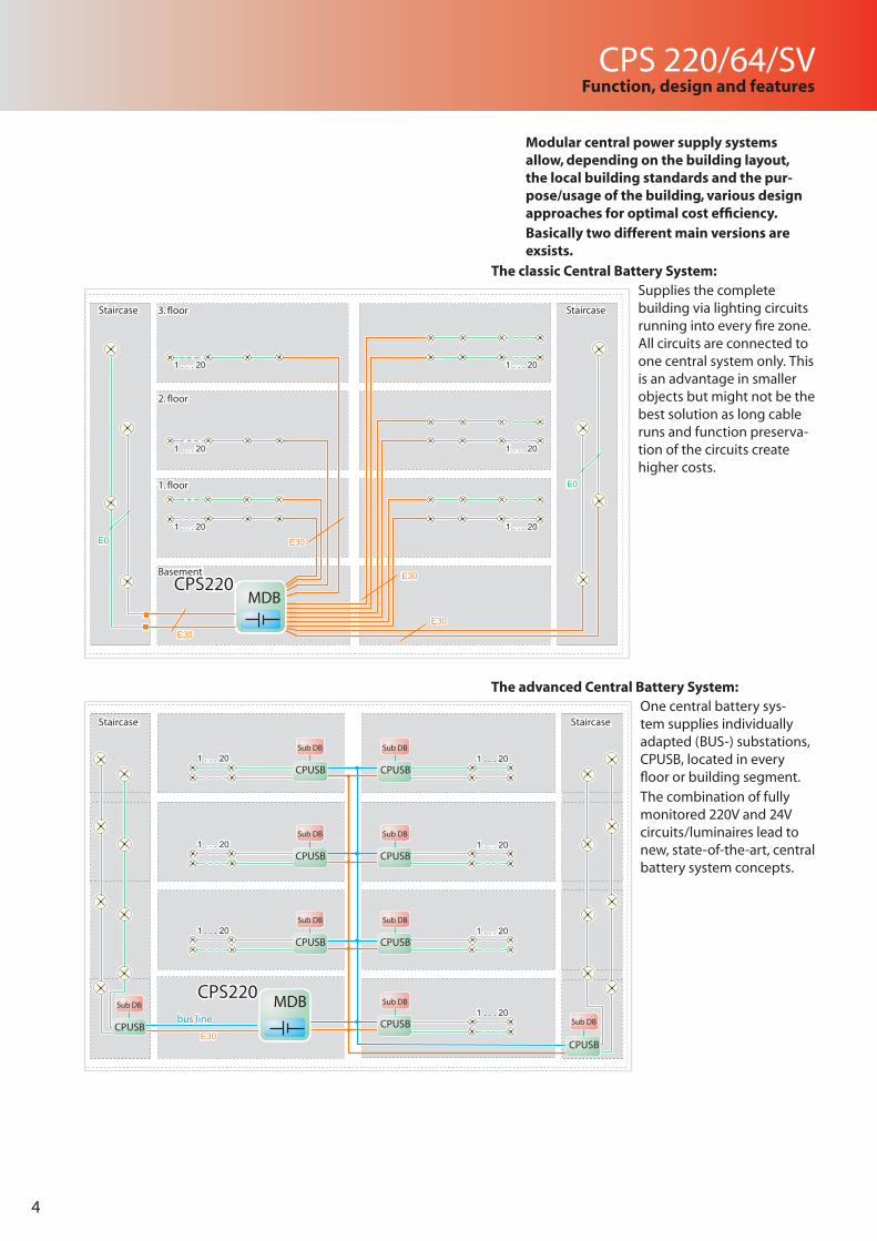
One central battery sys-tem supplies individually adapted (BUS-) substations, CPUSB, located in every floor or building segment.The combination of fully monitored 220V and 24V circuits/luminaires lead to new, state-of-the-art, central battery system concepts.
CPS220CPS220
1 . . . 20
1 . . . 20
1 . . . 20
1 . . . 20
1 . . . 20
1 . . . 20
E0
1 . . . 20
1 . . . 20
1 . . . 20
1 . . . 20
1 . . . 20
1 . . . 20
E0
E30
E30
3. floorStaircase Staircase
2. floor
1. floor
Basement
E30
E30
E30
E30 E0
E30
E30 E0
Staircase Staircase
MDB
Basement
1. floor
2. floor
3. floor
1 . . . 20 1 . . . 20
1 . . . 20
1 . . . 20
1 . . . 20
1 . . . 20
1 . . . 20
CPUSB
CPUSB
CPUSB
CPUSB
CPUSB
CPUSB
CPUSB
CPUSB
CPUSB
CPS220CPS220
E30 E30
1 . . . 20 1 . . . 20
1 . . . 20
1 . . . 20
1 . . . 20
1 . . . 20
1 . . . 20
Staircase StaircaseStaircase Staircase
Sub DB
Sub DB
Sub DB
Sub DB
MDB
Sub DB
Sub DB
Sub DB
Sub DB
Sub DB
bus linebus line
Modular central power supply systems allow, depending on the building layout, the local building standards and the pur-pose/usage of the building, various design approaches for optimal cost efficiency.Basically two different main versions are exsists.
Supplies the complete building via lighting circuits running into every fire zone. All circuits are connected to one central system only. This is an advantage in smaller objects but might not be the best solution as long cable runs and function preserva-tion of the circuits create higher costs.
The advanced Central Battery System:
The classic Central Battery System:
CPS 220/64/SVFunction, design and features
5
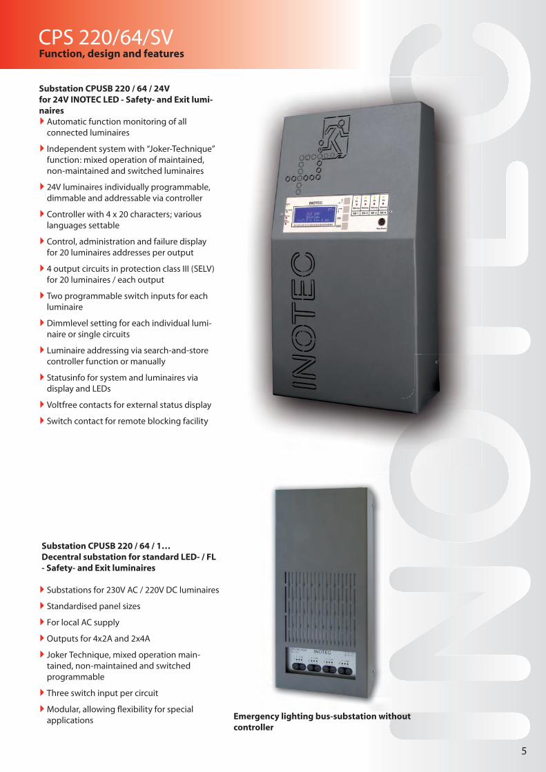
Substation CPUSB 220 / 64 / 1…Decentral substation for standard LED- / FL - Safety- and Exit luminaires
` Substations for 230V AC / 220V DC luminaires
` Standardised panel sizes
` For local AC supply
` Outputs for 4x2A and 2x4A
` Joker Technique, mixed operation main-tained, non-maintained and switched programmable
` Three switch input per circuit
`Modular, allowing fl exibility for special applications
Substation CPUSB 220 / 64 / 24Vfor 24V INOTEC LED - Safety- and Exit lumi-naires
` Automatic function monitoring of all connected luminaires
` Independent system with “Joker-Technique” function: mixed operation of maintained, non-maintained and switched luminaires
` 24V luminaires individually programmable, dimmable and addressable via controller
` Controller with 4 x 20 characters; various languages settable
` Control, administration and failure display for 20 luminaires addresses per output
` 4 output circuits in protection class III (SELV) for 20 luminaires / each output
` Two programmable switch inputs for each luminaire
` Dimmlevel setting for each individual lumi-naire or single circuits
` Luminaire addressing via search-and-store controller function or manually
` Statusinfo for system and luminaires via display and LEDs
` Voltfree contacts for external status display
` Switch contact for remote blocking facility
Emergency lighting bus-substation without controller
6
CPS 220/64/SVFunction, design and features
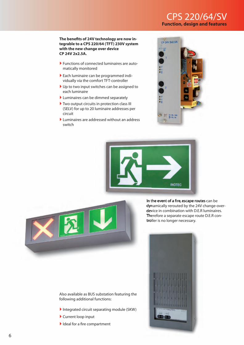
Also available as BUS substation featuring the following additional functions:
` Integrated circuit separating module (SKW)
` Current loop input
` Ideal for a fi re compartment
The benefi ts of 24V technology are now in-tegrable to a CPS 220/64 (TFT) 230V system with the new change over device CP 24V 2x2.5A.
` Functions of connected luminaires are auto-matically monitored
` Each luminaire can be programmed indi-vidually via the comfort TFT-controller
` Up to two input switches can be assigned to each luminaire
` Luminaires can be dimmed separately
` Two output circuits in protection class III (SELV) for up to 20 luminaire addresses per circuit
` Luminaires are addressed without an address switch
In the event of a fi re, escape routes can be dynamically rerouted by the 24V change-over-device in combination with D.E.R luminaires. Therefore a separate escape route D.E.R con-troller is no longer necessary.
dynamically rerouted by the 24V change-over-device in combination with D.E.R luminaires. Therefore a separate escape route D.E.R con-troller is no longer necessary.
In the event of a fi re, escape routes can be In the event of a fi re, escape routes can be
CPS 220/64/SVFunction, design and features
7
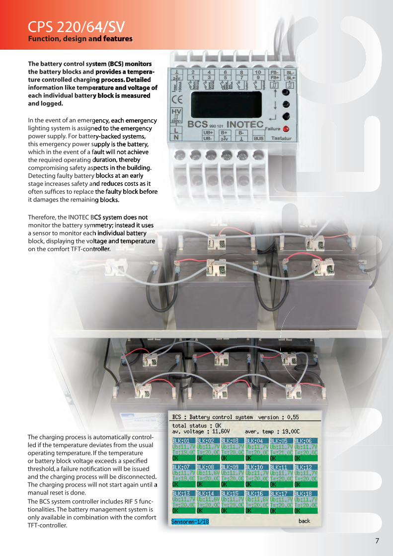
The charging process is automatically control-led if the temperature deviates from the usual operating temperature. If the temperature or battery block voltage exceeds a specifi ed threshold, a failure notifi cation will be issued and the charging process will be disconnected. The charging process will not start again until a manual reset is done.The BCS system controller includes RIF 5 func-tionalities. The battery management system is only available in combination with the comfort TFT-controller.
The battery control system (BCS) monitors the battery blocks and provides a tempera-ture controlled charging process. Detailed information like temperature and voltage of each individual battery block is measured and logged.
In the event of an emergency, each emergency lighting system is assigned to the emergency power supply. For battery-backed systems, this emergency power supply is the battery, which in the event of a fault will not achieve the required operating duration, thereby compromising safety aspects in the building. Detecting faulty battery blocks at an early stage increases safety and reduces costs as it often suffi ces to replace the faulty block before it damages the remaining blocks.
Therefore, the INOTEC BCS system does not monitor the battery symmetry; instead it uses a sensor to monitor each individual battery block, displaying the voltage and temperature on the comfort TFT-controller.
and the charging process will be disconnected. The charging process will not start again until a
only available in combination with the comfort
CPS 220/64/SVFunction, design and features
The battery control system (BCS) monitors the battery blocks and provides a tempera-ture controlled charging process. Detailed information like temperature and voltage of each individual battery block is measured
In the event of an emergency, each emergency lighting system is assigned to the emergency power supply. For battery-backed systems, this emergency power supply is the battery, which in the event of a fault will not achieve the required operating duration, thereby compromising safety aspects in the building. Detecting faulty battery blocks at an early stage increases safety and reduces costs as it often suffi ces to replace the faulty block before it damages the remaining blocks.
Therefore, the INOTEC BCS system does not monitor the battery symmetry; instead it uses a sensor to monitor each individual battery block, displaying the voltage and temperature on the comfort TFT-controller.
8
CPS 220/64/SVFunction, design and features
8
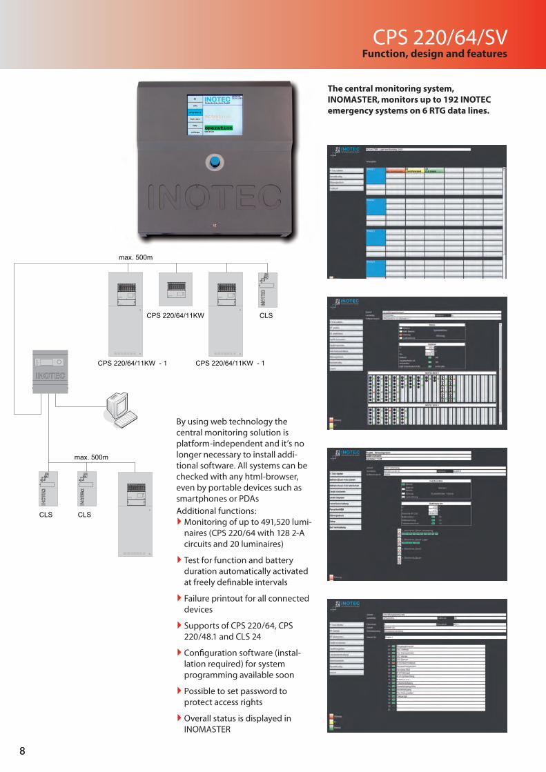
By using web technology the central monitoring solution is platform-independent and it’s no longer necessary to install addi-tional software. All systems can be checked with any html-browser, even by portable devices such as smartphones or PDAsAdditional functions:
`Monitoring of up to 491,520 lumi-naires (CPS 220/64 with 128 2-A circuits and 20 luminaires)
` Test for function and battery duration automatically activated at freely defi nable intervals
` Failure printout for all connected devices
` Supports of CPS 220/64, CPS 220/48.1 and CLS 24
` Confi guration software (instal-lation required) for system programming available soon
` Possible to set password to protect access rights
` Overall status is displayed in INOMASTER
The central monitoring system, INOMASTER, monitors up to 192 INOTEC emergency systems on 6 RTG data lines.
StörungFailure
Batt.-BetriebBat.-Operation
BetriebOperation
1
2
3
4
CP 4x2A
F3,15 A
= BL / NM= DL / M
F3,15 A
F3,15 A
F3,15 A
1
2
3
4
CP 4x2A
F3,15 A
= BL / NM= DL / M
F3,15 A
F3,15 A
F3,15 A
1
2
3
4
CP 4x2A
F3,15 A
= BL / NM= DL / M
F3,15 A
F3,15 A
F3,15 A
1
2
3
4
CP 4x2A
F3,15 A
= BL / NM= DL / M
F3,15 A
F3,15 A
F3,15 A
1
2
3
4
CP 4x2A
F3,15 A
= BL / NM= DL / M
F3,15 A
F3,15 A
F3,15 A
1
2
3
4
CP 4x2A
F3,15 A
= BL / NM= DL / M
F3,15 A
F3,15 A
F3,15 A
1
2
3
4
CP 4x2A
F3,15 A
= BL / NM= DL / M
F3,15 A
F3,15 A
F3,15 A
1
2
3
4
CP 4x2A
F3,15 A
= BL / NM= DL / M
F3,15 A
F3,15 A
F3,15 A
1
2
3
4
CP 4x2A
F3,15 A
= BL / NM= DL / M
F3,15 A
F3,15 A
F3,15 A
1
2
3
4
CP 4x2A
F3,15 A
= BL / NM= DL / M
F3,15 A
F3,15 A
F3,15 A
1
2
3
4
CP 4x2A
F3,15 A
= BL / NM= DL / M
F3,15 A
F3,15 A
F3,15 A
1
2
3
4
CP 4x2A
F3,15 A
= BL / NM= DL / M
F3,15 A
F3,15 A
F3,15 A
1
2
3
4
CP 4x2A
F3,15 A
= BL / NM= DL / M
F3,15 A
F3,15 A
F3,15 A
1
2
3
4
CP 4x2A
F3,15 A
= BL / NM= DL / M
F3,15 A
F3,15 A
F3,15 A
1
2
3
4
CP 4x2A
F3,15 A
= BL / NM= DL / M
F3,15 A
F3,15 A
F3,15 A
1
2
3
4
CP 4x2A
F3,15 A
= BL / NM= DL / M
F3,15 A
F3,15 A
F3,15 A
CPS 220 / 64
Netz
Ladeteil 220V/7,5A
Ein
10AT16AT
Batterie
1
2
3
4
CP 4x2A
F3,15 A
= BL / NM= DL / M
F3,15 A
F3,15 A
F3,15 A
1
2
3
4
CP 4x2A
F3,15 A
= BL / NM= DL / M
F3,15 A
F3,15 A
F3,15 A
1
2
3
4
CP 4x2A
F3,15 A
= BL / NM= DL / M
F3,15 A
F3,15 A
F3,15 A
1
2
3
4
CP 4x2A
F3,15 A
= BL / NM= DL / M
F3,15 A
F3,15 A
F3,15 A
1
2
3
4
CP 4x2A
F3,15 A
= BL / NM= DL / M
F3,15 A
F3,15 A
F3,15 A
1
2
3
4
CP 4x2A
F3,15 A
= BL / NM= DL / M
F3,15 A
F3,15 A
F3,15 A
1
2
3
4
CP 4x2A
F3,15 A
= BL / NM= DL / M
F3,15 A
F3,15 A
F3,15 A
1
2
3
4
CP 4x2A
F3,15 A
= BL / NM= DL / M
F3,15 A
F3,15 A
F3,15 A
1
2
3
4
CP 4x2A
F3,15 A
= BL / NM= DL / M
F3,15 A
F3,15 A
F3,15 A
1
2
3
4
CP 4x2A
F3,15 A
= BL / NM= DL / M
F3,15 A
F3,15 A
F3,15 A
1
2
3
4
CP 4x2A
F3,15 A
= BL / NM= DL / M
F3,15 A
F3,15 A
F3,15 A
1
2
3
4
CP 4x2A
F3,15 A
= BL / NM= DL / M
F3,15 A
F3,15 A
F3,15 A
1
2
3
4
CP 4x2A
F3,15 A
= BL / NM= DL / M
F3,15 A
F3,15 A
F3,15 A
1
2
3
4
CP 4x2A
F3,15 A
= BL / NM= DL / M
F3,15 A
F3,15 A
F3,15 A
1
2
3
4
CP 4x2A
F3,15 A
= BL / NM= DL / M
F3,15 A
F3,15 A
F3,15 A
1
2
3
4
CP 4x2A
F3,15 A
= BL / NM= DL / M
F3,15 A
F3,15 A
F3,15 A
CPS 220 / 64
CPS 220/64/11KW - 1
CPS 220/64/11KW - 1
CPS 220/64/11KW - 1
CLS
CLS CLS
CPS 220/64/11KW
max. 500m
max. 500m
CPS 220/64/SVFunction, design and features
9
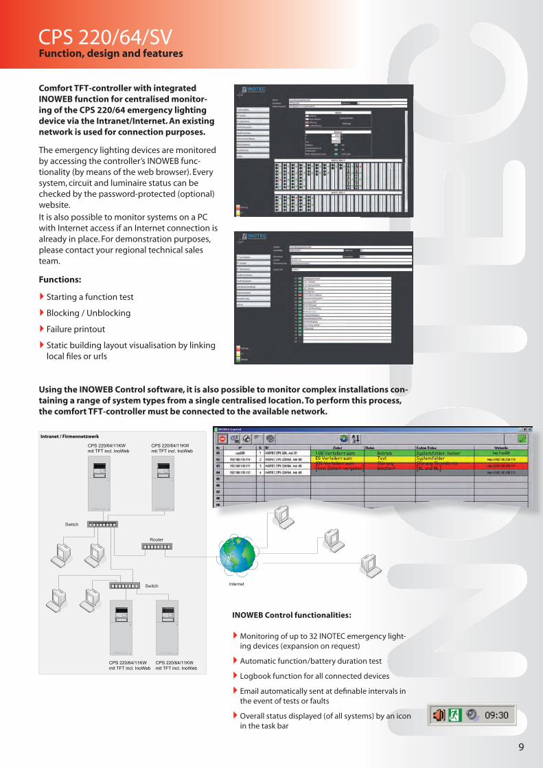
The emergency lighting devices are monitored by accessing the controller’s INOWEB func-tionality (by means of the web browser). Every system, circuit and luminaire status can be checked by the password-protected (optional) website. It is also possible to monitor systems on a PC with Internet access if an Internet connection is already in place. For demonstration purposes, please contact your regional technical sales team.
Functions:
` Starting a function test
` Blocking / Unblocking
` Failure printout
` Static building layout visualisation by linking local fi les or urls
Using the INOWEB Control software, it is also possible to monitor complex installations con-taining a range of system types from a single centralised location. To perform this process, the comfort TFT-controller must be connected to the available network.
Comfort TFT-controller with integrated INOWEB function for centralised monitor-ing of the CPS 220/64 emergency lighting device via the Intranet/Internet. An existing network is used for connection purposes.
1 UG Verteilerraum Betrieb Systemfehler: keinerEG Verteilerraum Test Systemfehler1OG Verteilerraum Störung Störung Stromkreis[kein Zielort vergeben] blockiert [DL und NL]
Internet
Router
Switch
Switch
Netz
Ladeteil 220V/7,5A
Ein
10AT16AT
Batterie
1
2
3
4
CP 4x2A
F3,15 A
= BL / NM= DL / M
F3,15 A
F3,15 A
F3,15 A
1
2
3
4
CP 4x2A
F3,15 A
= BL / NM= DL / M
F3,15 A
F3,15 A
F3,15 A
1
2
3
4
CP 4x2A
F3,15 A
= BL / NM= DL / M
F3,15 A
F3,15 A
F3,15 A
1
2
3
4
CP 4x2A
F3,15 A
= BL / NM= DL / M
F3,15 A
F3,15 A
F3,15 A
1
2
3
4
CP 4x2A
F3,15 A
= BL / NM= DL / M
F3,15 A
F3,15 A
F3,15 A
1
2
3
4
CP 4x2A
F3,15 A
= BL / NM= DL / M
F3,15 A
F3,15 A
F3,15 A
1
2
3
4
CP 4x2A
F3,15 A
= BL / NM= DL / M
F3,15 A
F3,15 A
F3,15 A
1
2
3
4
CP 4x2A
F3,15 A
= BL / NM= DL / M
F3,15 A
F3,15 A
F3,15 A
1
2
3
4
CP 4x2A
F3,15 A
= BL / NM= DL / M
F3,15 A
F3,15 A
F3,15 A
1
2
3
4
CP 4x2A
F3,15 A
= BL / NM= DL / M
F3,15 A
F3,15 A
F3,15 A
1
2
3
4
CP 4x2A
F3,15 A
= BL / NM= DL / M
F3,15 A
F3,15 A
F3,15 A
1
2
3
4
CP 4x2A
F3,15 A
= BL / NM= DL / M
F3,15 A
F3,15 A
F3,15 A
1
2
3
4
CP 4x2A
F3,15 A
= BL / NM= DL / M
F3,15 A
F3,15 A
F3,15 A
1
2
3
4
CP 4x2A
F3,15 A
= BL / NM= DL / M
F3,15 A
F3,15 A
F3,15 A
1
2
3
4
CP 4x2A
F3,15 A
= BL / NM= DL / M
F3,15 A
F3,15 A
F3,15 A
1
2
3
4
CP 4x2A
F3,15 A
= BL / NM= DL / M
F3,15 A
F3,15 A
F3,15 A
CPS 220 / 64
CPS 220/64/11KW mit TFT incl. InoWeb
CPS 220/64/11KW mit TFT incl. InoWeb
CPS 220/64/11KW mit TFT incl. InoWeb
CPS 220/64/11KW mit TFT incl. InoWeb
Intranet / Firmennetzwerk
INOWEB Control functionalities:
` Monitoring of up to 32 INOTEC emergency light-ing devices (expansion on request)
` Automatic function/battery duration test
` Logbook function for all connected devices
` Email automatically sent at defi nable intervals in the event of tests or faults
` Overall status displayed (of all systems) by an icon in the task bar
10
CPS 220/64/SV
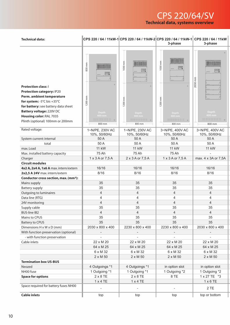
Technical data: CPS 220 / 64 / 11kW-1 CPS 220 / 64 / 11kW-2 CPS 220 / 64 / 11kW-1 3-phase
CPS 220 / 64 / 11kW 3-phase
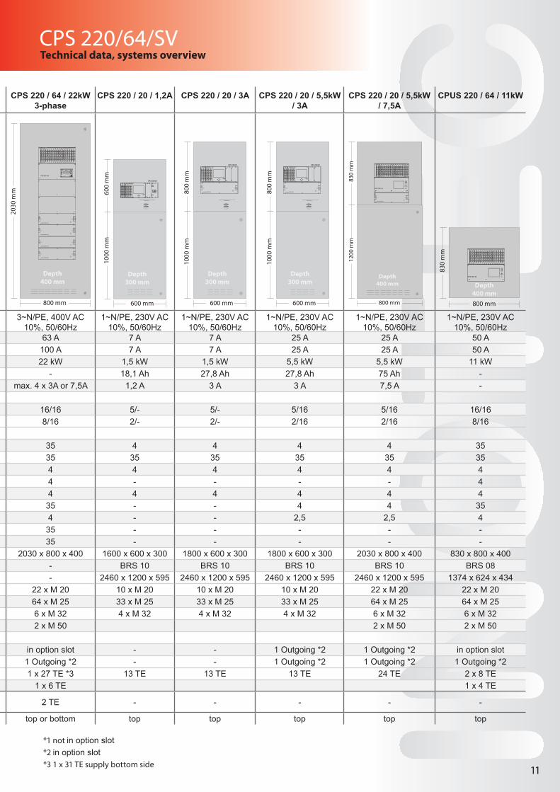
CPS 220 / 64 / 22kW 3-phase
CPS 220 / 20 / 1,2A CPS 220 / 20 / 3A CPS 220 / 20 / 5,5kW / 3A
CPS 220 / 20 / 5,5kW / 7,5A
CPUS 220 / 64 / 11kW
Protection class: I
Protection category: IP20
Perm. ambient temperature
for system: -5°C bis +35°C
for battery: see battery data sheet
Battery voltage: 220V DC
Housing color: RAL 7035
Plinth (optional) 100mm or 200mm
Rated voltage: 1~N/PE, 230V AC 10%, 50/60Hz
1~N/PE, 230V AC 10%, 50/60Hz
3~N/PE, 400V AC 10%, 50/60Hz
3~N/PE, 400V AC 10%, 50/60Hz
3~N/PE, 400V AC 10%, 50/60Hz
1~N/PE, 230V AC 10%, 50/60Hz
1~N/PE, 230V AC 10%, 50/60Hz
1~N/PE, 230V AC 10%, 50/60Hz
1~N/PE, 230V AC 10%, 50/60Hz
1~N/PE, 230V AC 10%, 50/60Hz
System current: internal 50 A 50 A 50 A 50 A 63 A 7 A 7 A 25 A 25 A 50 A total 50 A 50 A 50 A 50 A 100 A 7 A 7 A 25 A 25 A 50 Amax. Load 11 kW 11 kW 11 kW 11 kW 22 kW 1,5 kW 1,5 kW 5,5 kW 5,5 kW 11 kWMax. installed battery capacity 75 Ah 75 Ah 75 Ah - - 18,1 Ah 27,8 Ah 27,8 Ah 75 Ah -Charger 1 x 3 A or 7,5 A 2 x 3 A or 7,5 A 1 x 3 A or 7,5 A max. 4 x 3A or 7,5A max. 4 x 3A or 7,5A 1,2 A 3 A 3 A 7,5 A -Circuit modules
4x2 A, 2x4 A, 1x6 A max. intern/extern 16/16 16/16 16/16 16/16 16/16 5/- 5/- 5/16 5/16 16/162x2,5 A 24V max. intern/extern 8/16 8/16 8/16 8/16 8/16 2/- 2/- 2/16 2/16 8/16Conductor cross section, max. (mm²):
Mains supply 35 35 35 35 35 4 4 4 4 35Battery supply 35 35 35 35 35 35 35 35 35 35Outgoing to luminaires 4 4 4 4 4 4 4 4 4 4Data line (RTG) 4 4 4 4 4 - - - - 424V monitoring 4 4 4 4 4 4 4 4 4 4Supply cable 35 35 35 35 35 - - 4 4 35BUS-line IB2 4 4 4 4 4 - - 2,5 2,5 4Mains to CPUS 35 35 35 35 35 - - - - -Battery to CPUS 35 35 35 35 35 - - - - -Dimensions H x W x D (mm) 2030 x 800 x 400 2230 x 800 x 400 2230 x 800 x 400 2030 x 800 x 400 2030 x 800 x 400 1600 x 600 x 300 1800 x 600 x 300 1800 x 600 x 300 2030 x 800 x 400 830 x 800 x 400With function preservation (optional) - - - - - BRS 10 BRS 10 BRS 10 BRS 10 BRS 08 - with function preservation - - - - - 2460 x 1200 x 595 2460 x 1200 x 595 2460 x 1200 x 595 2460 x 1200 x 595 1374 x 624 x 434Cable inlets 22 x M 20 22 x M 20 22 x M 20 22 x M 20 22 x M 20 10 x M 20 10 x M 20 10 x M 20 22 x M 20 22 x M 20
64 x M 25 64 x M 25 64 x M 25 64 x M 25 64 x M 25 33 x M 25 33 x M 25 33 x M 25 64 x M 25 64 x M 256 x M 32 6 x M 32 6 x M 32 6 x M 32 6 x M 32 4 x M 32 4 x M 32 4 x M 32 6 x M 32 6 x M 322 x M 50 2 x M 50 2 x M 50 2 x M 50 2 x M 50 2 x M 50 2 x M 50
Termination box US-BUS
Neozed 4 Outgoings *1 4 Outgoings *1 in option slot in option slot in option slot - - 1 Outgoing *2 1 Outgoing *2 in option slotNH00 fuse 1 Outgoing *1 1 Outgoing *1 1 Outgoing *2 1 Outgoing *2 1 Outgoing *2 - - 1 Outgoing *2 1 Outgoing *2 1 Outgoing *2Space for options 2 x 8 TE 2 x 8 TE 8 TE 1 x 27 TE *3 1 x 27 TE *3 13 TE 13 TE 13 TE 24 TE 2 x 8 TE
1 x 4 TE 1 x 4 TE 1 x 6 TE 1 x 6 TE 1 x 4 TESpace required for battery fuses NH00
- - - 2 TE 2 TE - - - - -
Cable inlets top top top top or bottom top or bottom top top top top top
Technical data, systems overview
830
mm
1200
mm
800 mm
Depth400 mm
Netz
Ladeteil 220V/7,5A
CPS 220 / 64
Ein
10AT16AT
Batterie
Batt.-Betrieb
Störung
Lade-Störung
INOTEC
Drucker Centronics
ResetR T
Key-Board
Betrieb
1
2
3
4
CP 4x2A
F3,15 A
= BL / NM= DL / M
F3,15 A
F3,15 A
F3,15 A
1
2
3
4
CP 4x2A
F3,15 A
= BL / NM= DL / M
F3,15 A
F3,15 A
F3,15 A
1
2
3
4
CP 4x2A
F3,15 A
= BL / NM= DL / M
F3,15 A
F3,15 A
F3,15 A
1
2
3
4
CP 4x2A
F3,15 A
= BL / NM= DL / M
F3,15 A
F3,15 A
F3,15 A
1
2
3
4
CP 4x2A
F3,15 A
= BL / NM= DL / M
F3,15 A
F3,15 A
F3,15 A
1
2
3
4
CP 4x2A
F3,15 A
= BL / NM= DL / M
F3,15 A
F3,15 A
F3,15 A
1
2
3
4
CP 4x2A
F3,15 A
= BL / NM= DL / M
F3,15 A
F3,15 A
F3,15 A
1
2
3
4
CP 4x2A
F3,15 A
= BL / NM= DL / M
F3,15 A
F3,15 A
F3,15 A
1
2
3
4
CP 4x2A
F3,15 A
= BL / NM= DL / M
F3,15 A
F3,15 A
F3,15 A
1
2
3
4
CP 4x2A
F3,15 A
= BL / NM= DL / M
F3,15 A
F3,15 A
F3,15 A
1
2
3
4
CP 4x2A
F3,15 A
= BL / NM= DL / M
F3,15 A
F3,15 A
F3,15 A
1
2
3
4
CP 4x2A
F3,15 A
= BL / NM= DL / M
F3,15 A
F3,15 A
F3,15 A
1
2
3
4
CP 4x2A
F3,15 A
= BL / NM= DL / M
F3,15 A
F3,15 A
F3,15 A
1
2
3
4
CP 4x2A
F3,15 A
= BL / NM= DL / M
F3,15 A
F3,15 A
F3,15 A
1
2
3
4
CP 4x2A
F3,15 A
= BL / NM= DL / M
F3,15 A
F3,15 A
F3,15 A
1
2
3
4
CP 4x2A
F3,15 A
= BL / NM= DL / M
F3,15 A
F3,15 A
F3,15 A
1030
mm
1200
mm
800 mm
Depth400 mm
Netz
Ladeteil 220V/7,5A
CPS 220 / 64
Ein
10AT16AT
Batterie
Netz
Ladeteil 220V/7,5A
Ein
10AT16AT
Batterie
Batt.-Betrieb
Störung
Lade-Störung
INOTEC
Drucker Centronics
ResetR T
Key-Board
Betrieb
1
2
3
4
CP 4x2A
F3,15 A
= BL / NM= DL / M
F3,15 A
F3,15 A
F3,15 A
1
2
3
4
CP 4x2A
F3,15 A
= BL / NM= DL / M
F3,15 A
F3,15 A
F3,15 A
1
2
3
4
CP 4x2A
F3,15 A
= BL / NM= DL / M
F3,15 A
F3,15 A
F3,15 A
1
2
3
4
CP 4x2A
F3,15 A
= BL / NM= DL / M
F3,15 A
F3,15 A
F3,15 A
1
2
3
4
CP 4x2A
F3,15 A
= BL / NM= DL / M
F3,15 A
F3,15 A
F3,15 A
1
2
3
4
CP 4x2A
F3,15 A
= BL / NM= DL / M
F3,15 A
F3,15 A
F3,15 A
1
2
3
4
CP 4x2A
F3,15 A
= BL / NM= DL / M
F3,15 A
F3,15 A
F3,15 A
1
2
3
4
CP 4x2A
F3,15 A
= BL / NM= DL / M
F3,15 A
F3,15 A
F3,15 A
1
2
3
4
CP 4x2A
F3,15 A
= BL / NM= DL / M
F3,15 A
F3,15 A
F3,15 A
1
2
3
4
CP 4x2A
F3,15 A
= BL / NM= DL / M
F3,15 A
F3,15 A
F3,15 A
1
2
3
4
CP 4x2A
F3,15 A
= BL / NM= DL / M
F3,15 A
F3,15 A
F3,15 A
1
2
3
4
CP 4x2A
F3,15 A
= BL / NM= DL / M
F3,15 A
F3,15 A
F3,15 A
1
2
3
4
CP 4x2A
F3,15 A
= BL / NM= DL / M
F3,15 A
F3,15 A
F3,15 A
1
2
3
4
CP 4x2A
F3,15 A
= BL / NM= DL / M
F3,15 A
F3,15 A
F3,15 A
1
2
3
4
CP 4x2A
F3,15 A
= BL / NM= DL / M
F3,15 A
F3,15 A
F3,15 A
1
2
3
4
CP 4x2A
F3,15 A
= BL / NM= DL / M
F3,15 A
F3,15 A
F3,15 A
1030
mm
1200
mm
800 mm
Depth400 mm
Netz
Ladeteil 220V/7,5A
CPS 220 / 64
Ein
10AT16AT
Batterie
Batt.-Betrieb
Störung
Lade-Störung
INOTEC
Drucker Centronics
ResetR T
Key-Board
Betrieb
1
2
3
4
CP 4x2A
F3,15 A
= BL / NM= DL / M
F3,15 A
F3,15 A
F3,15 A
1
2
3
4
CP 4x2A
F3,15 A
= BL / NM= DL / M
F3,15 A
F3,15 A
F3,15 A
1
2
3
4
CP 4x2A
F3,15 A
= BL / NM= DL / M
F3,15 A
F3,15 A
F3,15 A
1
2
3
4
CP 4x2A
F3,15 A
= BL / NM= DL / M
F3,15 A
F3,15 A
F3,15 A
1
2
3
4
CP 4x2A
F3,15 A
= BL / NM= DL / M
F3,15 A
F3,15 A
F3,15 A
1
2
3
4
CP 4x2A
F3,15 A
= BL / NM= DL / M
F3,15 A
F3,15 A
F3,15 A
1
2
3
4
CP 4x2A
F3,15 A
= BL / NM= DL / M
F3,15 A
F3,15 A
F3,15 A
1
2
3
4
CP 4x2A
F3,15 A
= BL / NM= DL / M
F3,15 A
F3,15 A
F3,15 A
1
2
3
4
CP 4x2A
F3,15 A
= BL / NM= DL / M
F3,15 A
F3,15 A
F3,15 A
1
2
3
4
CP 4x2A
F3,15 A
= BL / NM= DL / M
F3,15 A
F3,15 A
F3,15 A
1
2
3
4
CP 4x2A
F3,15 A
= BL / NM= DL / M
F3,15 A
F3,15 A
F3,15 A
1
2
3
4
CP 4x2A
F3,15 A
= BL / NM= DL / M
F3,15 A
F3,15 A
F3,15 A
1
2
3
4
CP 4x2A
F3,15 A
= BL / NM= DL / M
F3,15 A
F3,15 A
F3,15 A
1
2
3
4
CP 4x2A
F3,15 A
= BL / NM= DL / M
F3,15 A
F3,15 A
F3,15 A
1
2
3
4
CP 4x2A
F3,15 A
= BL / NM= DL / M
F3,15 A
F3,15 A
F3,15 A
1
2
3
4
CP 4x2A
F3,15 A
= BL / NM= DL / M
F3,15 A
F3,15 A
F3,15 A
2030
mm
800 mm
Depth400 mm
Netz
Ladeteil 220V/7,5A
CPS 220 / 64
Ein
10AT16AT
Batterie
Netz
Ladeteil 220V/7,5A
Ein
10AT16AT
Batterie
Netz
Ladeteil 220V/7,5A
Ein
10AT16AT
Batterie
Netz
Ladeteil 220V/7,5A
Ein
10AT16AT
Batterie
Batt.-Betrieb
Störung
Lade-Störung
INOTEC
Drucker Centronics
ResetR T
Key-Board
Betrieb
1
2
3
4
CP 4x2A
F3,15 A
= BL / NM= DL / M
F3,15 A
F3,15 A
F3,15 A
1
2
3
4
CP 4x2A
F3,15 A
= BL / NM= DL / M
F3,15 A
F3,15 A
F3,15 A
1
2
3
4
CP 4x2A
F3,15 A
= BL / NM= DL / M
F3,15 A
F3,15 A
F3,15 A
1
2
3
4
CP 4x2A
F3,15 A
= BL / NM= DL / M
F3,15 A
F3,15 A
F3,15 A
1
2
3
4
CP 4x2A
F3,15 A
= BL / NM= DL / M
F3,15 A
F3,15 A
F3,15 A
1
2
3
4
CP 4x2A
F3,15 A
= BL / NM= DL / M
F3,15 A
F3,15 A
F3,15 A
1
2
3
4
CP 4x2A
F3,15 A
= BL / NM= DL / M
F3,15 A
F3,15 A
F3,15 A
1
2
3
4
CP 4x2A
F3,15 A
= BL / NM= DL / M
F3,15 A
F3,15 A
F3,15 A
1
2
3
4
CP 4x2A
F3,15 A
= BL / NM= DL / M
F3,15 A
F3,15 A
F3,15 A
1
2
3
4
CP 4x2A
F3,15 A
= BL / NM= DL / M
F3,15 A
F3,15 A
F3,15 A
1
2
3
4
CP 4x2A
F3,15 A
= BL / NM= DL / M
F3,15 A
F3,15 A
F3,15 A
1
2
3
4
CP 4x2A
F3,15 A
= BL / NM= DL / M
F3,15 A
F3,15 A
F3,15 A
1
2
3
4
CP 4x2A
F3,15 A
= BL / NM= DL / M
F3,15 A
F3,15 A
F3,15 A
1
2
3
4
CP 4x2A
F3,15 A
= BL / NM= DL / M
F3,15 A
F3,15 A
F3,15 A
1
2
3
4
CP 4x2A
F3,15 A
= BL / NM= DL / M
F3,15 A
F3,15 A
F3,15 A
1
2
3
4
CP 4x2A
F3,15 A
= BL / NM= DL / M
F3,15 A
F3,15 A
F3,15 A
CPS 220/64/SV
Technical data: CPS 220 / 64 / 11kW-1 CPS 220 / 64 / 11kW-2 CPS 220 / 64 / 11kW-1 3-phase
CPS 220 / 64 / 11kW 3-phase
CPS 220 / 64 / 22kW 3-phase
CPS 220 / 20 / 1,2A CPS 220 / 20 / 3A CPS 220 / 20 / 5,5kW / 3A
CPS 220 / 20 / 5,5kW / 7,5A
CPUS 220 / 64 / 11kW
Protection class: I
Protection category: IP20
Perm. ambient temperature
for system: -5°C bis +35°C
for battery: see battery data sheet
Battery voltage: 220V DC
Housing color: RAL 7035
Plinth (optional) 100mm or 200mm
Rated voltage: 1~N/PE, 230V AC 10%, 50/60Hz
1~N/PE, 230V AC 10%, 50/60Hz
3~N/PE, 400V AC 10%, 50/60Hz
3~N/PE, 400V AC 10%, 50/60Hz
3~N/PE, 400V AC 10%, 50/60Hz
1~N/PE, 230V AC 10%, 50/60Hz
1~N/PE, 230V AC 10%, 50/60Hz
1~N/PE, 230V AC 10%, 50/60Hz
1~N/PE, 230V AC 10%, 50/60Hz
1~N/PE, 230V AC 10%, 50/60Hz
System current: internal 50 A 50 A 50 A 50 A 63 A 7 A 7 A 25 A 25 A 50 A total 50 A 50 A 50 A 50 A 100 A 7 A 7 A 25 A 25 A 50 Amax. Load 11 kW 11 kW 11 kW 11 kW 22 kW 1,5 kW 1,5 kW 5,5 kW 5,5 kW 11 kWMax. installed battery capacity 75 Ah 75 Ah 75 Ah - - 18,1 Ah 27,8 Ah 27,8 Ah 75 Ah -Charger 1 x 3 A or 7,5 A 2 x 3 A or 7,5 A 1 x 3 A or 7,5 A max. 4 x 3A or 7,5A max. 4 x 3A or 7,5A 1,2 A 3 A 3 A 7,5 A -Circuit modules
4x2 A, 2x4 A, 1x6 A max. intern/extern 16/16 16/16 16/16 16/16 16/16 5/- 5/- 5/16 5/16 16/162x2,5 A 24V max. intern/extern 8/16 8/16 8/16 8/16 8/16 2/- 2/- 2/16 2/16 8/16Conductor cross section, max. (mm²):
Mains supply 35 35 35 35 35 4 4 4 4 35Battery supply 35 35 35 35 35 35 35 35 35 35Outgoing to luminaires 4 4 4 4 4 4 4 4 4 4Data line (RTG) 4 4 4 4 4 - - - - 424V monitoring 4 4 4 4 4 4 4 4 4 4Supply cable 35 35 35 35 35 - - 4 4 35BUS-line IB2 4 4 4 4 4 - - 2,5 2,5 4Mains to CPUS 35 35 35 35 35 - - - - -Battery to CPUS 35 35 35 35 35 - - - - -Dimensions H x W x D (mm) 2030 x 800 x 400 2230 x 800 x 400 2230 x 800 x 400 2030 x 800 x 400 2030 x 800 x 400 1600 x 600 x 300 1800 x 600 x 300 1800 x 600 x 300 2030 x 800 x 400 830 x 800 x 400With function preservation (optional) - - - - - BRS 10 BRS 10 BRS 10 BRS 10 BRS 08 - with function preservation - - - - - 2460 x 1200 x 595 2460 x 1200 x 595 2460 x 1200 x 595 2460 x 1200 x 595 1374 x 624 x 434Cable inlets 22 x M 20 22 x M 20 22 x M 20 22 x M 20 22 x M 20 10 x M 20 10 x M 20 10 x M 20 22 x M 20 22 x M 20
64 x M 25 64 x M 25 64 x M 25 64 x M 25 64 x M 25 33 x M 25 33 x M 25 33 x M 25 64 x M 25 64 x M 256 x M 32 6 x M 32 6 x M 32 6 x M 32 6 x M 32 4 x M 32 4 x M 32 4 x M 32 6 x M 32 6 x M 322 x M 50 2 x M 50 2 x M 50 2 x M 50 2 x M 50 2 x M 50 2 x M 50
Termination box US-BUS
Neozed 4 Outgoings *1 4 Outgoings *1 in option slot in option slot in option slot - - 1 Outgoing *2 1 Outgoing *2 in option slotNH00 fuse 1 Outgoing *1 1 Outgoing *1 1 Outgoing *2 1 Outgoing *2 1 Outgoing *2 - - 1 Outgoing *2 1 Outgoing *2 1 Outgoing *2Space for options 2 x 8 TE 2 x 8 TE 8 TE 1 x 27 TE *3 1 x 27 TE *3 13 TE 13 TE 13 TE 24 TE 2 x 8 TE
1 x 4 TE 1 x 4 TE 1 x 6 TE 1 x 6 TE 1 x 4 TESpace required for battery fuses NH00
- - - 2 TE 2 TE - - - - -
Cable inlets top top top top or bottom top or bottom top top top top top
Technical data, systems overview
11
*1 not in option slot*2 in option slot*3 1 x 31 TE supply bottom side
600
mm
1000
mm
600 mm
Depth300 mm
CPS 220/20
1
2
3
4
CP 4x2A
F3,15 A
= BL / NM= DL / M
F3,15 A
F3,15 A
F3,15 A
1
2
3
4
CP 4x2A
F3,15 A
= BL / NM= DL / M
F3,15 A
F3,15 A
F3,15 A
1
2
3
4
CP 4x2A
F3,15 A
= BL / NM= DL / M
F3,15 A
F3,15 A
F3,15 A
1
2
3
4
CP 4x2A
F3,15 A
= BL / NM= DL / M
F3,15 A
F3,15 A
F3,15 A
1
2
3
4
CP 4x2A AIF CPS 220/20 LT 220V / 1,2A
DC –
AC ~I
3,15A
AC ~3,15A
U
F3,15 A
= BL / NM= DL / M
F3,15 A
F3,15 A
F3,15 A
Achtung!! Sicherungen im Gerät nicht unter Last ziehen. Anlage blockieren.
Batteriesicherung
10A
10A
hin ter d er B lende
DC – 800
mm
1000
mm
600 mm
Depth300 mm
CPS 220/20
1
2
3
4
CP 4x2A
F3,15 A
= BL / NM= DL / M
F3,15 A
F3,15 A
F3,15 A
1
2
3
4
CP 4x2A
F3,15 A
= BL / NM= DL / M
F3,15 A
F3,15 A
F3,15 A
1
2
3
4
CP 4x2A
F3,15 A
= BL / NM= DL / M
F3,15 A
F3,15 A
F3,15 A
1
2
3
4
CP 4x2A
F3,15 A
= BL / NM= DL / M
F3,15 A
F3,15 A
F3,15 A
1
2
3
4
CP 4x2A
F3,15 A
= BL / NM= DL / M
F3,15 A
F3,15 A
F3,15 A
Achtung!! Sicherungen im Gerät nicht unter Last ziehen. Anlage blockieren.
Batteriesicherung
10A
10A
hinter d er B lende
Netz
Ladeteil 220V/7,5A
Ein
10AT16AT
Batterie
800
mm
1000
mm
600 mm
Depth300 mm
CPS 220/20
1
2
3
4
CP 4x2A
F3,15 A
= BL / NM= DL / M
F3,15 A
F3,15 A
F3,15 A
1
2
3
4
CP 4x2A
F3,15 A
= BL / NM= DL / M
F3,15 A
F3,15 A
F3,15 A
1
2
3
4
CP 4x2A
F3,15 A
= BL / NM= DL / M
F3,15 A
F3,15 A
F3,15 A
1
2
3
4
CP 4x2A
F3,15 A
= BL / NM= DL / M
F3,15 A
F3,15 A
F3,15 A
1
2
3
4
CP 4x2A
F3,15 A
= BL / NM= DL / M
F3,15 A
F3,15 A
F3,15 A
Achtung!! Sicherungen im Gerät nicht unter Last ziehen. Anlage blockieren.
Batteriesicherung
10A
10A
hinter d er B lende
Netz
Ladeteil 220V/7,5A
Ein
10AT16AT
Batterie
2030
mm
800 mm
Depth400 mm
CPS 220 / 64
Netz
Ladeteil 220V/7,5A
Ein
10AT16AT
Batterie
Netz
Ladeteil 220V/7,5A
Ein
10AT16AT
Batterie
Netz
Ladeteil 220V/7,5A
Ein
10AT16AT
Batterie
Netz
Ladeteil 220V/7,5A
Ein
10AT16AT
Batterie
Batt.-Betrieb
Störung
Lade-Störung
INOTEC
Drucker Centronics
ResetR T
Key-Board
Betrieb
1
2
3
4
CP 4x2A
F3,15 A
= BL / NM= DL / M
F3,15 A
F3,15 A
F3,15 A
1
2
3
4
CP 4x2A
F3,15 A
= BL / NM= DL / M
F3,15 A
F3,15 A
F3,15 A
1
2
3
4
CP 4x2A
F3,15 A
= BL / NM= DL / M
F3,15 A
F3,15 A
F3,15 A
1
2
3
4
CP 4x2A
F3,15 A
= BL / NM= DL / M
F3,15 A
F3,15 A
F3,15 A
1
2
3
4
CP 4x2A
F3,15 A
= BL / NM= DL / M
F3,15 A
F3,15 A
F3,15 A
1
2
3
4
CP 4x2A
F3,15 A
= BL / NM= DL / M
F3,15 A
F3,15 A
F3,15 A
1
2
3
4
CP 4x2A
F3,15 A
= BL / NM= DL / M
F3,15 A
F3,15 A
F3,15 A
1
2
3
4
CP 4x2A
F3,15 A
= BL / NM= DL / M
F3,15 A
F3,15 A
F3,15 A
1
2
3
4
CP 4x2A
F3,15 A
= BL / NM= DL / M
F3,15 A
F3,15 A
F3,15 A
1
2
3
4
CP 4x2A
F3,15 A
= BL / NM= DL / M
F3,15 A
F3,15 A
F3,15 A
1
2
3
4
CP 4x2A
F3,15 A
= BL / NM= DL / M
F3,15 A
F3,15 A
F3,15 A
1
2
3
4
CP 4x2A
F3,15 A
= BL / NM= DL / M
F3,15 A
F3,15 A
F3,15 A
1
2
3
4
CP 4x2A
F3,15 A
= BL / NM= DL / M
F3,15 A
F3,15 A
F3,15 A
1
2
3
4
CP 4x2A
F3,15 A
= BL / NM= DL / M
F3,15 A
F3,15 A
F3,15 A
1
2
3
4
CP 4x2A
F3,15 A
= BL / NM= DL / M
F3,15 A
F3,15 A
F3,15 A
1
2
3
4
CP 4x2A
F3,15 A
= BL / NM= DL / M
F3,15 A
F3,15 A
F3,15 A
830
mm
1200
mm
800 mm
Depth400 mm
Netz
Ladeteil 220V/7,5A
Ein
10AT16AT
Batterie
1
2
3
4
CP 4x2A
F3,15 A
= BL / NM= DL / M
F3,15 A
F3,15 A
F3,15 A
1
2
3
4
CP 4x2A
F3,15 A
= BL / NM= DL / M
F3,15 A
F3,15 A
F3,15 A
1
2
3
4
CP 4x2A
F3,15 A
= BL / NM= DL / M
F3,15 A
F3,15 A
F3,15 A
1
2
3
4
CP 4x2A
F3,15 A
= BL / NM= DL / M
F3,15 A
F3,15 A
F3,15 A
1
2
3
4
CP 4x2A
F3,15 A
= BL / NM= DL / M
F3,15 A
F3,15 A
F3,15 A
1
2
3
4
CP 4x2A
F3,15 A
= BL / NM= DL / M
F3,15 A
F3,15 A
F3,15 A
1
2
3
4
CP 4x2A
F3,15 A
= BL / NM= DL / M
F3,15 A
F3,15 A
F3,15 A
1
2
3
4
CP 4x2A
F3,15 A
= BL / NM= DL / M
F3,15 A
F3,15 A
F3,15 A
1
2
3
4
CP 4x2A
F3,15 A
= BL / NM= DL / M
F3,15 A
F3,15 A
F3,15 A
1
2
3
4
CP 4x2A
F3,15 A
= BL / NM= DL / M
F3,15 A
F3,15 A
F3,15 A
1
2
3
4
CP 4x2A
F3,15 A
= BL / NM= DL / M
F3,15 A
F3,15 A
F3,15 A
1
2
3
4
CP 4x2A
F3,15 A
= BL / NM= DL / M
F3,15 A
F3,15 A
F3,15 A
1
2
3
4
CP 4x2A
F3,15 A
= BL / NM= DL / M
F3,15 A
F3,15 A
F3,15 A
1
2
3
4
CP 4x2A
F3,15 A
= BL / NM= DL / M
F3,15 A
F3,15 A
F3,15 A
1
2
3
4
CP 4x2A
F3,15 A
= BL / NM= DL / M
F3,15 A
F3,15 A
F3,15 A
1
2
3
4
CP 4x2A
F3,15 A
= BL / NM= DL / M
F3,15 A
F3,15 A
F3,15 A
CPS 220 / 64
830
mm
800 mm
1
2
3
4
CP 4x2A
F3,15 A
= BL / NM= DL / M
F3,15 A
F3,15 A
F3,15 A
1
2
3
4
CP 4x2A
F3,15 A
= BL / NM= DL / M
F3,15 A
F3,15 A
F3,15 A
1
2
3
4
CP 4x2A
F3,15 A
= BL / NM= DL / M
F3,15 A
F3,15 A
F3,15 A
1
2
3
4
CP 4x2A
F3,15 A
= BL / NM= DL / M
F3,15 A
F3,15 A
F3,15 A
1
2
3
4
CP 4x2A
F3,15 A
= BL / NM= DL / M
F3,15 A
F3,15 A
F3,15 A
1
2
3
4
CP 4x2A
F3,15 A
= BL / NM= DL / M
F3,15 A
F3,15 A
F3,15 A
1
2
3
4
CP 4x2A
F3,15 A
= BL / NM= DL / M
F3,15 A
F3,15 A
F3,15 A
1
2
3
4
CP 4x2A
F3,15 A
= BL / NM= DL / M
F3,15 A
F3,15 A
F3,15 A
1
2
3
4
CP 4x2A
F3,15 A
= BL / NM= DL / M
F3,15 A
F3,15 A
F3,15 A
1
2
3
4
CP 4x2A
F3,15 A
= BL / NM= DL / M
F3,15 A
F3,15 A
F3,15 A
1
2
3
4
CP 4x2A
F3,15 A
= BL / NM= DL / M
F3,15 A
F3,15 A
F3,15 A
1
2
3
4
CP 4x2A
F3,15 A
= BL / NM= DL / M
F3,15 A
F3,15 A
F3,15 A
1
2
3
4
CP 4x2A
F3,15 A
= BL / NM= DL / M
F3,15 A
F3,15 A
F3,15 A
1
2
3
4
CP 4x2A
F3,15 A
= BL / NM= DL / M
F3,15 A
F3,15 A
F3,15 A
1
2
3
4
CP 4x2A
F3,15 A
= BL / NM= DL / M
F3,15 A
F3,15 A
F3,15 A
1
2
3
4
CP 4x2A
F3,15 A
= BL / NM= DL / M
F3,15 A
F3,15 A
F3,15 A
CPS 220 / 64
Depth400 mm
CPS 220/64/SVTechnical data, systems overview
Required space for options
0 TE 1 TE 2 TE 4 TE 6 TE 7 TE
Mains terminals for sub-station (single-phase system)
DPÜ DPÜ / B.1 LSA 8.1 LSA 8.1 24, incl. 4 terminals
Fuse protection Battery NH00
RIF 5 Fuse output NH00 for substation
BCS
PSU 24
Fuse output Neozed for substation
Mains terminals for sub-station (3-phase system)
12
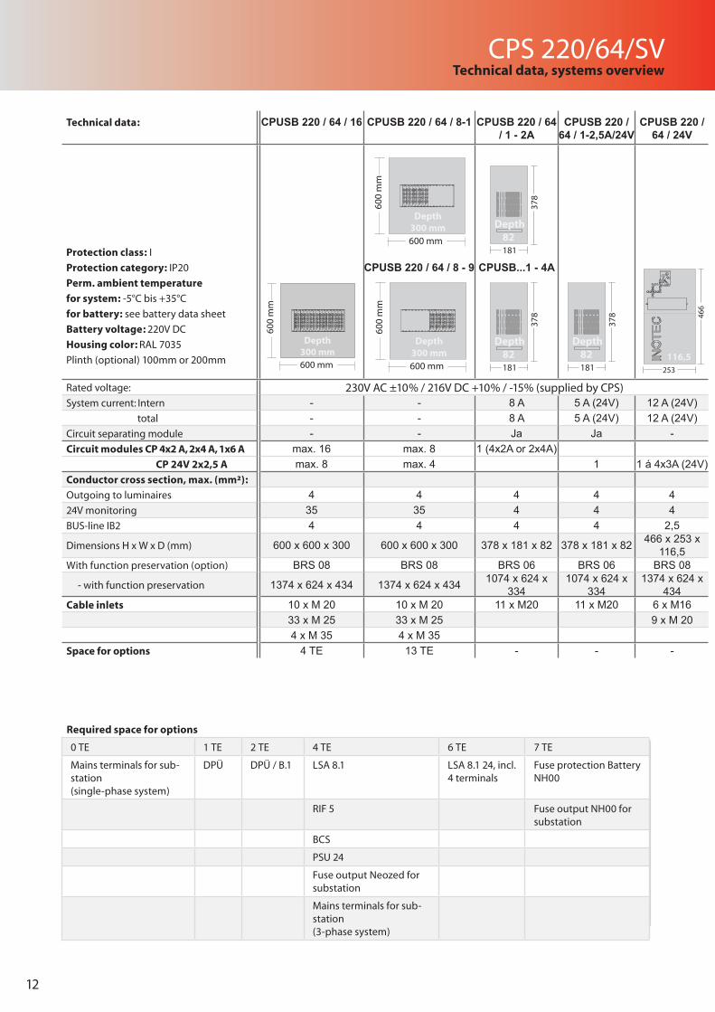
Technical data: CPUSB 220 / 64 / 16 CPUSB 220 / 64 / 8-1 CPUSB 220 / 64 / 1 - 2A
CPUSB 220 / 64 / 1-2,5A/24V
CPUSB 220 / 64 / 24V
Protection class: I
Protection category: IP20
Perm. ambient temperature
for system: -5°C bis +35°C
for battery: see battery data sheet
Battery voltage: 220V DC
Housing color: RAL 7035
Plinth (optional) 100mm or 200mm
CPUSB 220 / 64 / 8 - 9 CPUSB...1 - 4A
Rated voltage: 230V AC ±10% / 216V DC +10% / -15% (supplied by CPS)System current: Intern - - 8 A 5 A (24V) 12 A (24V) total - - 8 A 5 A (24V) 12 A (24V)Circuit separating module - - Ja Ja -Circuit modules CP 4x2 A, 2x4 A, 1x6 A max. 16 max. 8 1 (4x2A or 2x4A) CP 24V 2x2,5 A max. 8 max. 4 1 1 á 4x3A (24V)Conductor cross section, max. (mm²):
Outgoing to luminaires 4 4 4 4 424V monitoring 35 35 4 4 4BUS-line IB2 4 4 4 4 2,5
Dimensions H x W x D (mm) 600 x 600 x 300 600 x 600 x 300 378 x 181 x 82 378 x 181 x 82 466 x 253 x 116,5
With function preservation (option) BRS 08 BRS 08 BRS 06 BRS 06 BRS 08
- with function preservation 1374 x 624 x 434 1374 x 624 x 434 1074 x 624 x 334
1074 x 624 x 334
1374 x 624 x 434
Cable inlets 10 x M 20 10 x M 20 11 x M20 11 x M20 6 x M1633 x M 25 33 x M 25 9 x M 204 x M 35 4 x M 35
Space for options 4 TE 13 TE - - -
600 mm
600
mm
Depth300 mm
1
2
3
4
CP 4x2A
F3,15 A
= BL / NM= DL / M
F3,15 A
F3,15 A
F3,15 A
1
2
3
4
CP 4x2A
F3,15 A
= BL / NM= DL / M
F3,15 A
F3,15 A
F3,15 A
1
2
3
4
CP 4x2A
F3,15 A
= BL / NM= DL / M
F3,15 A
F3,15 A
F3,15 A
1
2
3
4
CP 4x2A
F3,15 A
= BL / NM= DL / M
F3,15 A
F3,15 A
F3,15 A
1
2
3
4
CP 4x2A
F3,15 A
= BL / NM= DL / M
F3,15 A
F3,15 A
F3,15 A
1
2
3
4
CP 4x2A
F3,15 A
= BL / NM= DL / M
F3,15 A
F3,15 A
F3,15 A
1
2
3
4
CP 4x2A
F3,15 A
= BL / NM= DL / M
F3,15 A
F3,15 A
F3,15 A
1
2
3
4
CP 4x2A
F3,15 A
= BL / NM= DL / M
F3,15 A
F3,15 A
F3,15 A
600 mm60
0 m
m
Depth300 mm
1
2
3
4
CP 4x2A
F3,15 A
= BL / NM= DL / M
F3,15 A
F3,15 A
F3,15 A
1
2
3
4
CP 4x2A
F3,15 A
= BL / NM= DL / M
F3,15 A
F3,15 A
F3,15 A
1
2
3
4
CP 4x2A
F3,15 A
= BL / NM= DL / M
F3,15 A
F3,15 A
F3,15 A
1
2
3
4
CP 4x2A
F3,15 A
= BL / NM= DL / M
F3,15 A
F3,15 A
F3,15 A
1
2
3
4
CP 4x2A
F3,15 A
= BL / NM= DL / M
F3,15 A
F3,15 A
F3,15 A
1
2
3
4
CP 4x2A
F3,15 A
= BL / NM= DL / M
F3,15 A
F3,15 A
F3,15 A
1
2
3
4
CP 4x2A
F3,15 A
= BL / NM= DL / M
F3,15 A
F3,15 A
F3,15 A
1
2
3
4
CP 4x2A
F3,15 A
= BL / NM= DL / M
F3,15 A
F3,15 A
F3,15 A
600 mm
600
mm
1
2
3
4
CP 4x2A
F3,15 A
= BL / NM= DL / M
F3,15 A
F3,15 A
F3,15 A
1
2
3
4
CP 4x2A
F3,15 A
= BL / NM= DL / M
F3,15 A
F3,15 A
F3,15 A
1
2
3
4
CP 4x2A
F3,15 A
= BL / NM= DL / M
F3,15 A
F3,15 A
F3,15 A
1
2
3
4
CP 4x2A
F3,15 A
= BL / NM= DL / M
F3,15 A
F3,15 A
F3,15 A
1
2
3
4
CP 4x2A
F3,15 A
= BL / NM= DL / M
F3,15 A
F3,15 A
F3,15 A
1
2
3
4
CP 4x2A
F3,15 A
= BL / NM= DL / M
F3,15 A
F3,15 A
F3,15 A
1
2
3
4
CP 4x2A
F3,15 A
= BL / NM= DL / M
F3,15 A
F3,15 A
F3,15 A
1
2
3
4
CP 4x2A
F3,15 A
= BL / NM= DL / M
F3,15 A
F3,15 A
F3,15 A
1
2
3
4
CP 4x2A
F3,15 A
= BL / NM= DL / M
F3,15 A
F3,15 A
F3,15 A
1
2
3
4
CP 4x2A
F3,15 A
= BL / NM= DL / M
F3,15 A
F3,15 A
F3,15 A
1
2
3
4
CP 4x2A
F3,15 A
= BL / NM= DL / M
F3,15 A
F3,15 A
F3,15 A
1
2
3
4
CP 4x2A
F3,15 A
= BL / NM= DL / M
F3,15 A
F3,15 A
F3,15 A
1
2
3
4
CP 4x2A
F3,15 A
= BL / NM= DL / M
F3,15 A
F3,15 A
F3,15 A
1
2
3
4
CP 4x2A
F3,15 A
= BL / NM= DL / M
F3,15 A
F3,15 A
F3,15 A
1
2
3
4
CP 4x2A
F3,15 A
= BL / NM= DL / M
F3,15 A
F3,15 A
F3,15 A
1
2
3
4
CP 4x2A
F3,15 A
= BL / NM= DL / M
F3,15 A
F3,15 A
F3,15 A
Depth300 mm
378
181
Depth82
378
181
Depth82
378
181
Depth82
253
466
116,5
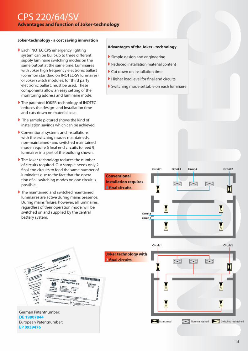
Joker-technology - a cost saving innovation
` Each INOTEC CPS emergency lighting system can be built-up to three different supply luminaire switching modes on the same output at the same time. Luminaires with Joker high frequency electronic ballast (common standard on INOTEC-SV lumnaires) or Joker switch modules, for third party electronic ballast, must be used. These components allow an easy setting of the monitoring address and luminaire mode.
` The patented JOKER-technology of INOTEC reduces the design- and installation time and cuts down on material cost.
` The sample pictured shows the kind of installation savings which can be achieved.
` Conventional systems and installations with the switching modes maintained-, non-maintained- and switched maintained mode, require 6 final end circuits to feed 9 lumnaires in a part of the building shown.
` The Joker-technology reduces the number of circuits required. Our sample needs only 2 final end circuits to feed the same number of luminaires due to the fact that the opera-tion of all switching modes on one circuit is possible.
` The maintained and switched maintained luminaires are active during mains presence. During mains failure, however, all luminaires, regardless of their operation mode, will be switched on and supplied by the central battery system.
Conventional
installation requires
6 final circuits
Joker technology with
2 final circuits
CPS 220/64/SVAdvantages and function of Joker-technology
13
Advantages of the Joker - technology
` Simple design and engineering
` Reduced installation material content
` Cut down on installation time
` Higher load level for final end circuits
` Switching mode settable on each luminaire
German Patentnumber:DE 19807844European Patentnumber:EP 0939476
Maintained Non-maintained Switched maintained
Circuit 1 Circuit 2
Circuit 3 Circuit4Circuit 1
Circuit 5
Circuit 6
Circuit 2
Technical data: CPUSB 220 / 64 / 16 CPUSB 220 / 64 / 8-1 CPUSB 220 / 64 / 1 - 2A
CPUSB 220 / 64 / 1-2,5A/24V
CPUSB 220 / 64 / 24V
Protection class: I
Protection category: IP20
Perm. ambient temperature
for system: -5°C bis +35°C
for battery: see battery data sheet
Battery voltage: 220V DC
Housing color: RAL 7035
Plinth (optional) 100mm or 200mm
CPUSB 220 / 64 / 8 - 9 CPUSB...1 - 4A
Rated voltage: 230V AC ±10% / 216V DC +10% / -15% (supplied by CPS)System current: Intern - - 8 A 5 A (24V) 12 A (24V) total - - 8 A 5 A (24V) 12 A (24V)Circuit separating module - - Ja Ja -Circuit modules CP 4x2 A, 2x4 A, 1x6 A max. 16 max. 8 1 (4x2A or 2x4A) CP 24V 2x2,5 A max. 8 max. 4 1 1 á 4x3A (24V)Conductor cross section, max. (mm²):
Outgoing to luminaires 4 4 4 4 424V monitoring 35 35 4 4 4BUS-line IB2 4 4 4 4 2,5
Dimensions H x W x D (mm) 600 x 600 x 300 600 x 600 x 300 378 x 181 x 82 378 x 181 x 82 466 x 253 x 116,5
With function preservation (option) BRS 08 BRS 08 BRS 06 BRS 06 BRS 08
- with function preservation 1374 x 624 x 434 1374 x 624 x 434 1074 x 624 x 334
1074 x 624 x 334
1374 x 624 x 434
Cable inlets 10 x M 20 10 x M 20 11 x M20 11 x M20 6 x M1633 x M 25 33 x M 25 9 x M 204 x M 35 4 x M 35
Space for options 4 TE 13 TE - - -
14
CPS 220/64/SVSystemkomponenten und Optionen
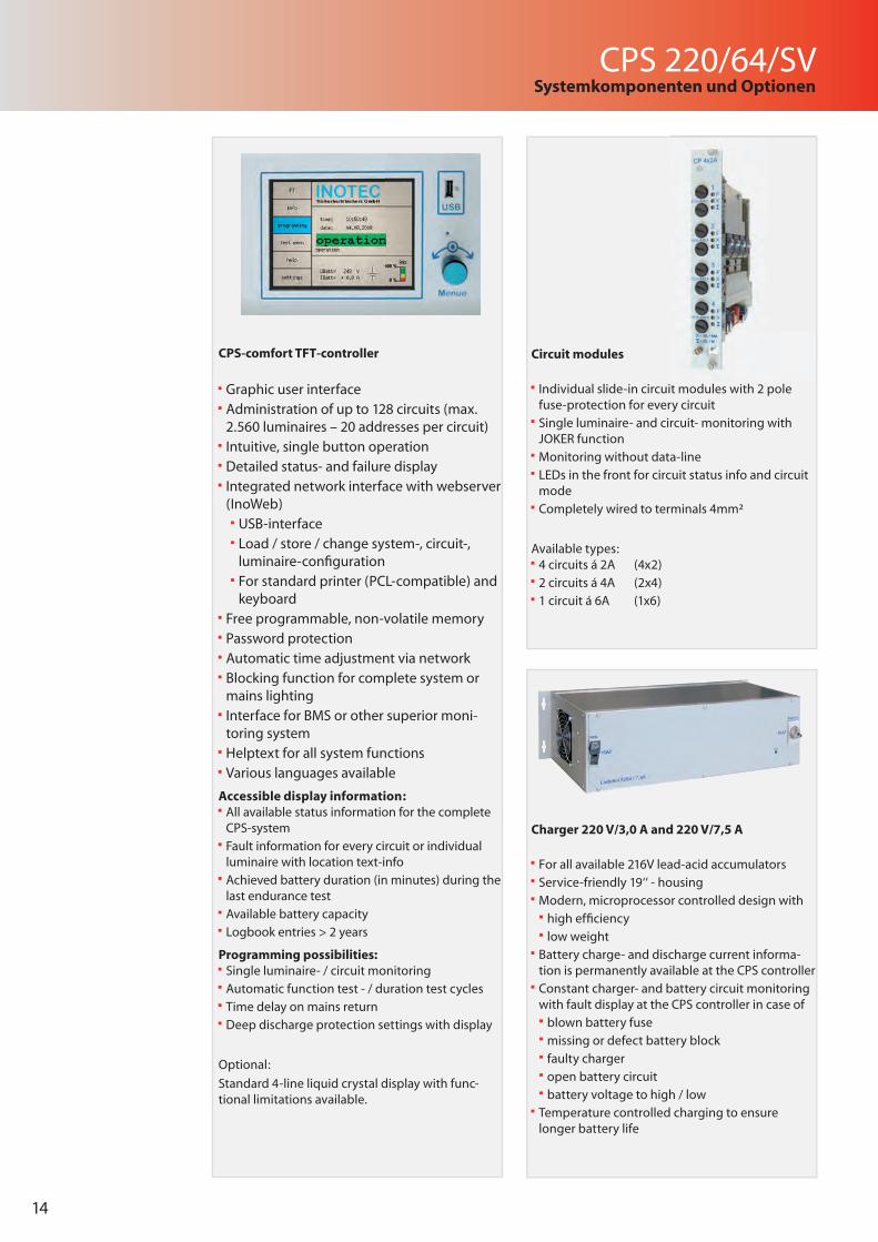
Circuit modules
Individual slide-in circuit modules with 2 pole fuse-protection for every circuit
Single luminaire- and circuit- monitoring with JOKER function
Monitoring without data-line
LEDs in the front for circuit status info and circuit mode
Completely wired to terminals 4mm²
Available types: 4 circuits á 2A (4x2)
2 circuits á 4A (2x4)
1 circuit á 6A (1x6)
CPS-comfort TFT-controller
Graphic user interface Administration of up to 128 circuits (max. 2.560 luminaires – 20 addresses per circuit)
Intuitive, single button operation Detailed status- and failure display Integrated network interface with webserver (InoWeb)
USB-interface Load / store / change system-, circuit-, luminaire-confi guration
For standard printer (PCL-compatible) and keyboard
Free programmable, non-volatile memory Password protection Automatic time adjustment via network Blocking function for complete system or mains lighting
Interface for BMS or other superior moni-toring system
Helptext for all system functions Various languages available
Accessible display information: All available status information for the complete CPS-system
Fault information for every circuit or individual luminaire with location text-info
Achieved battery duration (in minutes) during the last endurance test
Available battery capacity
Logbook entries > 2 years
Programming possibilities: Single luminaire- / circuit monitoring
Automatic function test - / duration test cycles
Time delay on mains return
Deep discharge protection settings with display
Optional:
Standard 4-line liquid crystal display with func-tional limitations available.
Charger 220 V/3,0 A and 220 V/7,5 A
For all available 216V lead-acid accumulators
Service-friendly 19‘‘ - housing
Modern, microprocessor controlled design with
high effi ciency
low weight
Battery charge- and discharge current informa-tion is permanently available at the CPS controller
Constant charger- and battery circuit monitoring with fault display at the CPS controller in case of
blown battery fuse
missing or defect battery block
faulty charger
open battery circuit
battery voltage to high / low
Temperature controlled charging to ensure longer battery life
CPS 220/64/SV
15
Systemkomponenten und Optionen
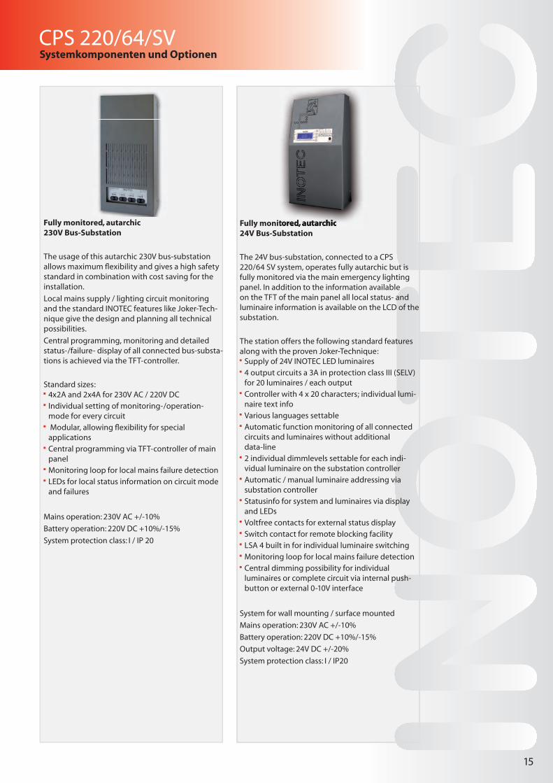
Fully monitored, autarchic 24V Bus-Substation
The 24V bus-substation, connected to a CPS 220/64 SV system, operates fully autarchic but is fully monitored via the main emergency lighting panel. In addition to the information available on the TFT of the main panel all local status- and luminaire information is available on the LCD of the substation.
The station offers the following standard features along with the proven Joker-Technique: Supply of 24V INOTEC LED luminaires
4 output circuits a 3A in protection class III (SELV) for 20 luminaires / each output
Controller with 4 x 20 characters; individual lumi-naire text info
Various languages settable
Automatic function monitoring of all connected circuits and luminaires without additional data-line
2 individual dimmlevels settable for each indi-vidual luminaire on the substation controller
Automatic / manual luminaire addressing via substation controller
Statusinfo for system and luminaires via display and LEDs
Voltfree contacts for external status display
Switch contact for remote blocking facility
LSA 4 built in for individual luminaire switching
Monitoring loop for local mains failure detection
Central dimming possibility for individual luminaires or complete circuit via internal push-button or external 0-10V interface
System for wall mounting / surface mounted
Mains operation: 230V AC +/-10%
Battery operation: 220V DC +10%/-15%
Output voltage: 24V DC +/-20%
System protection class: I / IP20
Fully monitored, autarchic 230V Bus-Substation
The usage of this autarchic 230V bus-substation allows maximum fl exibility and gives a high safety standard in combination with cost saving for the installation.
Local mains supply / lighting circuit monitoring and the standard INOTEC features like Joker-Tech-nique give the design and planning all technical possibilities.
Central programming, monitoring and detailed status-/failure- display of all connected bus-substa-tions is achieved via the TFT-controller.
Standard sizes: 4x2A and 2x4A for 230V AC / 220V DC
Individual setting of monitoring-/operation-mode for every circuit
Modular, allowing fl exibility for special applications
Central programming via TFT-controller of main panel
Monitoring loop for local mains failure detection
LEDs for local status information on circuit mode and failures
Mains operation: 230V AC +/-10%
Battery operation: 220V DC +10%/-15%
System protection class: I / IP 20
Fully monitored, autarchic 24V Bus-Substation
16
CPS 220/64/SVExternal supervision and display
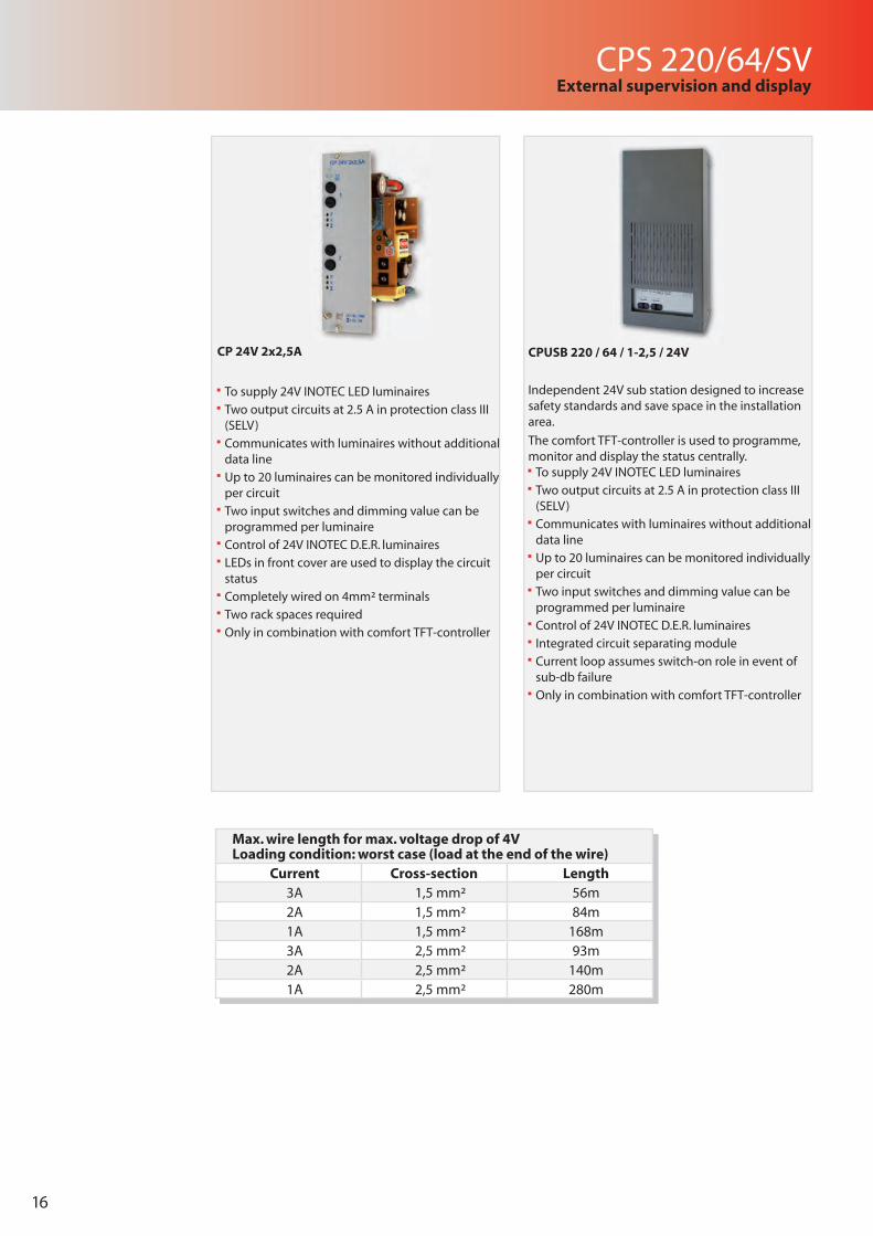
CPUSB 220 / 64 / 1-2,5 / 24V
Independent 24V sub station designed to increase safety standards and save space in the installation area.
The comfort TFT-controller is used to programme, monitor and display the status centrally. To supply 24V INOTEC LED luminaires
Two output circuits at 2.5 A in protection class III (SELV)
Communicates with luminaires without additional data line
Up to 20 luminaires can be monitored individually per circuit
Two input switches and dimming value can be programmed per luminaire
Control of 24V INOTEC D.E.R. luminaires
Integrated circuit separating module
Current loop assumes switch-on role in event of sub-db failure
Only in combination with comfort TFT-controller
CP 24V 2x2,5A
To supply 24V INOTEC LED luminaires
Two output circuits at 2.5 A in protection class III (SELV)
Communicates with luminaires without additional data line
Up to 20 luminaires can be monitored individually per circuit
Two input switches and dimming value can be programmed per luminaire
Control of 24V INOTEC D.E.R. luminaires
LEDs in front cover are used to display the circuit status
Completely wired on 4mm² terminals
Two rack spaces required
Only in combination with comfort TFT-controller
Max. wire length for max. voltage drop of 4VLoading condition: worst case (load at the end of the wire)
Current Cross-section Length 3A 1,5 mm² 56m2A 1,5 mm² 84m1A 1,5 mm² 168m3A 2,5 mm² 93m2A 2,5 mm² 140m1A 2,5 mm² 280m
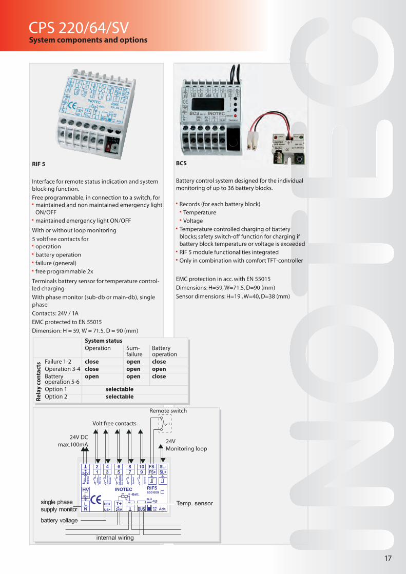
BCS
Battery control system designed for the individual monitoring of up to 36 battery blocks.
Records (for each battery block)
Temperature
Voltage
Temperature controlled charging of battery blocks; safety switch-off function for charging if battery block temperature or voltage is exceeded
RIF 5 module functionalities integrated
Only in combination with comfort TFT-controller
EMC protection in acc. with EN 55015
Dimensions: H=59, W=71.5, D=90 (mm)
Sensor dimensions: H=19 , W=40, D=38 (mm)
CPS 220/64/SV
17
System components and options
RIF 5
Interface for remote status indication and system blocking function.
Free programmable, in connection to a switch, for maintained and non maintained emergency light ON/OFF
maintained emergency light ON/OFF
With or without loop monitoring
5 voltfree contacts for operation
battery operation
failure (general)
free programmable 2x
Terminals battery sensor for temperature control-led charging
With phase monitor (sub-db or main-db), single phase
Contacts: 24V / 1A
EMC protected to EN 55015
Dimension: H = 59, W = 71.5, D = 90 (mm)
System statusOperation Sum- Battery
failure operationFailure 1-2 close open closeOperation 3-4 close open openBattery open open closeoperation 5-6Option 1 selectableOption 2 selectable
Rel
ay c
on
tact
s
internal wiring
Temp. sensor
24VMonitoring loop
24V DCmax.100mA
single phase supply monitor
battery voltage
Remote switch
Volt free contacts
850 009
18
CPS 220/64/SVSystemkomponenten und Optionen
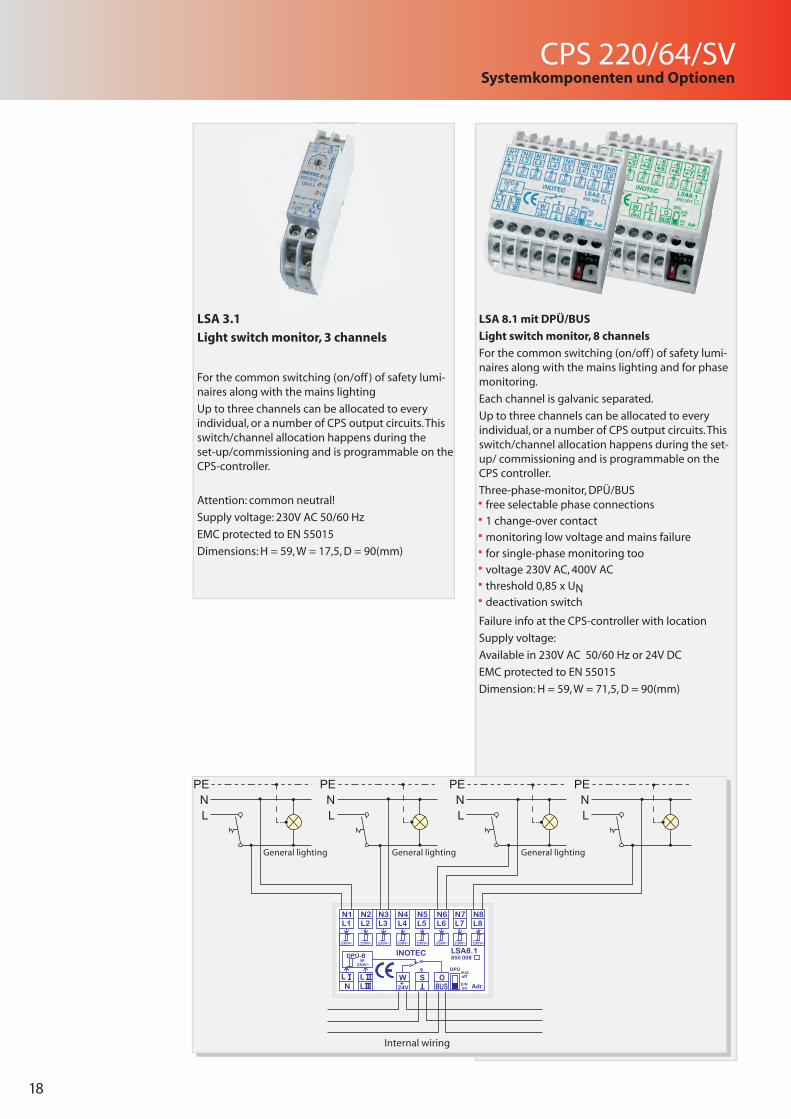
LSA 8.1 mit DPÜ/BUS
Light switch monitor, 8 channels
For the common switching (on/off ) of safety lumi-naires along with the mains lighting and for phase monitoring.
Each channel is galvanic separated.
Up to three channels can be allocated to every individual, or a number of CPS output circuits. This switch/channel allocation happens during the set-up/ commissioning and is programmable on the CPS controller.
Three-phase-monitor, DPÜ/BUS free selectable phase connections
1 change-over contact
monitoring low voltage and mains failure
for single-phase monitoring too
voltage 230V AC, 400V AC
threshold 0,85 x UN deactivation switch
Failure info at the CPS-controller with location
Supply voltage:
Available in 230V AC 50/60 Hz or 24V DC
EMC protected to EN 55015
Dimension: H = 59, W = 71,5, D = 90(mm)
LSA 3.1
Light switch monitor, 3 channels
For the common switching (on/off ) of safety lumi-naires along with the mains lighting
Up to three channels can be allocated to every individual, or a number of CPS output circuits. This switch/channel allocation happens during the set-up/commissioning and is programmable on the CPS-controller.
Attention: common neutral!
Supply voltage: 230V AC 50/60 Hz
EMC protected to EN 55015
Dimensions: H = 59, W = 17,5, D = 90(mm)
850 008
PENL
PENL
PENL
PENL
General lightingGeneral lightingGeneral lighting
Internal wiring
CPS 220/64/SV
19
Systemkomponenten und Optionen
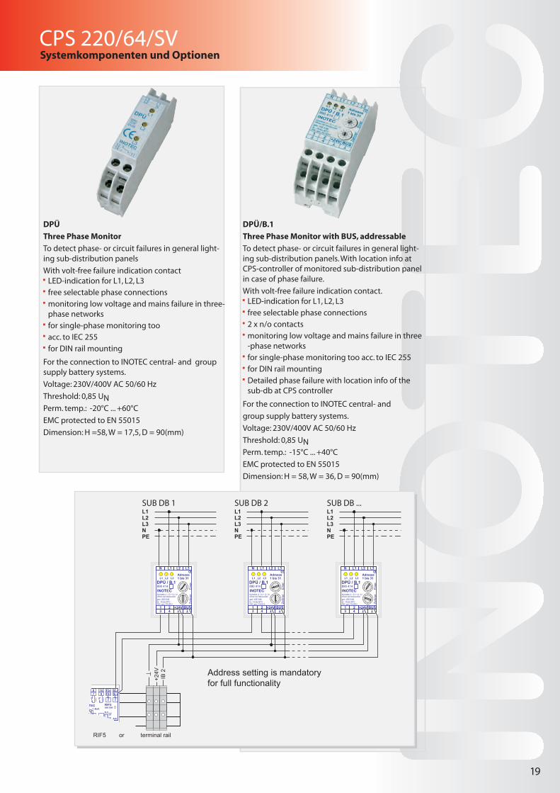
DPÜ/B.1
Three Phase Monitor with BUS, addressable
To detect phase- or circuit failures in general light-ing sub-distribution panels. With location info at CPS-controller of monitored sub-distribution panel in case of phase failure.
With volt-free failure indication contact. LED-indication for L1, L2, L3
free selectable phase connections
2 x n/o contacts
monitoring low voltage and mains failure in three -phase networks
for single-phase monitoring too acc. to IEC 255
for DIN rail mounting
Detailed phase failure with location info of the sub-db at CPS controller
For the connection to INOTEC central- and
group supply battery systems.
Voltage: 230V/400V AC 50/60 Hz
Threshold: 0,85 UNPerm. temp.: -15°C ... +40°C
EMC protected to EN 55015
Dimension: H = 58, W = 36, D = 90(mm)
DPÜ
Three Phase Monitor
To detect phase- or circuit failures in general light-ing sub-distribution panels
With volt-free failure indication contact LED-indication for L1, L2, L3
free selectable phase connections
monitoring low voltage and mains failure in three-phase networks
for single-phase monitoring too
acc. to IEC 255
for DIN rail mounting
For the connection to INOTEC central- and group supply battery systems.
Voltage: 230V/400V AC 50/60 Hz
Threshold: 0,85 UNPerm. temp.: -20°C ... +60°C
EMC protected to EN 55015
Dimension: H =58, W = 17,5, D = 90(mm)
850 009
01
23
45 6
78
9
01
23
45 6
78
9
gem. VDE 0108
EMC: gem. EN 55015ta: -15 bis 40°C
INOTEC
DPÜ / B.1890 414
L3L2L1
N L1 L2 L3
Kontakte (1 / 2) + (3 / 4)öffnen bei Netzausfall
Adresse1 bis 31
Ein
erZe
hner
+24V43
BUS1 2 T T
01
23
45 6
78
9
01
23
45 6
78
9
gem. VDE 0108
EMC: gem. EN 55015ta: -15 bis 40°C
INOTEC
DPÜ / B.1890 414
L3L2L1
N L1 L2 L3
Kontakte (1 / 2) + (3 / 4)öffnen bei Netzausfall
Adresse1 bis 31
Ein
erZe
hner
+24V43
BUS1 2 T T
01
23
45 6
78
9
01
23
45 6
78
9
gem. VDE 0108
EMC: gem. EN 55015ta: -15 bis 40°C
INOTEC
DPÜ / B.1890 414
L3L2L1
N L1 L2 L3
Kontakte (1 / 2) + (3 / 4)öffnen bei Netzausfall
Adresse1 bis 31
Ein
erZe
hner
+24V43
BUS1 2 T T
L1L2L3NPE
L1L2L3NPE
L1L2L3NPE
+24V
IB 2 Address setting is mandatory
for full functionality
SUB DB 1 SUB DB 2 SUB DB ...
RIF5 or terminal rail
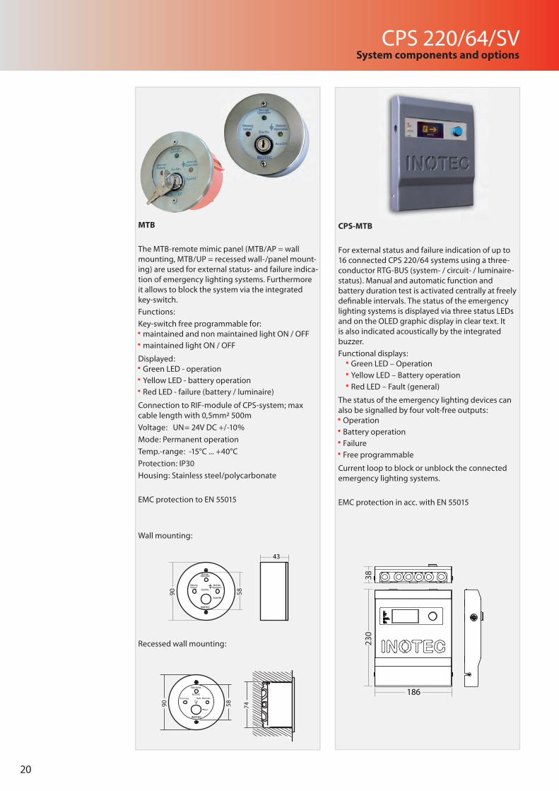
20
CPS 220/64/SVSystem components and options
MTB
The MTB-remote mimic panel (MTB/AP = wall mounting, MTB/UP = recessed wall-/panel mount-ing) are used for external status- and failure indica-tion of emergency lighting systems. Furthermore it allows to block the system via the integrated key-switch.
Functions:
Key-switch free programmable for: maintained and non maintained light ON / OFF
maintained light ON / OFF
Displayed: Green LED - operation
Yellow LED - battery operation
Red LED - failure (battery / luminaire)
Connection to RIF-module of CPS-system; max cable length with 0,5mm² 500m
Voltage: UN= 24V DC +/-10%
Mode: Permanent operation
Temp.-range: -15°C ... +40°C
Protection: IP30
Housing: Stainless steel/polycarbonate
EMC protection to EN 55015
Wall mounting:
Recessed wall mounting:
CPS-MTB
For external status and failure indication of up to 16 connected CPS 220/64 systems using a three-conductor RTG-BUS (system- / circuit- / luminaire-status). Manual and automatic function and battery duration test is activated centrally at freely defi nable intervals. The status of the emergency lighting systems is displayed via three status LEDs and on the OLED graphic display in clear text. It is also indicated acoustically by the integrated buzzer.
Functional displays: Green LED – Operation
Yellow LED – Battery operation
Red LED – Fault (general)
The status of the emergency lighting devices can also be signalled by four volt-free outputs: Operation
Battery operation
Failure
Free programmable
Current loop to block or unblock the connected emergency lighting systems.
EMC protection in acc. with EN 55015
230
38
186
74
90 58
Betrieb
Notlicht
INOTEC
Ein
Aus
Batt.-BetriebStörung
90
58
43
Aus/Off
Ein/On
Operation
Failure -Operation
INOTEC
Betrieb
Störung -Betrieb
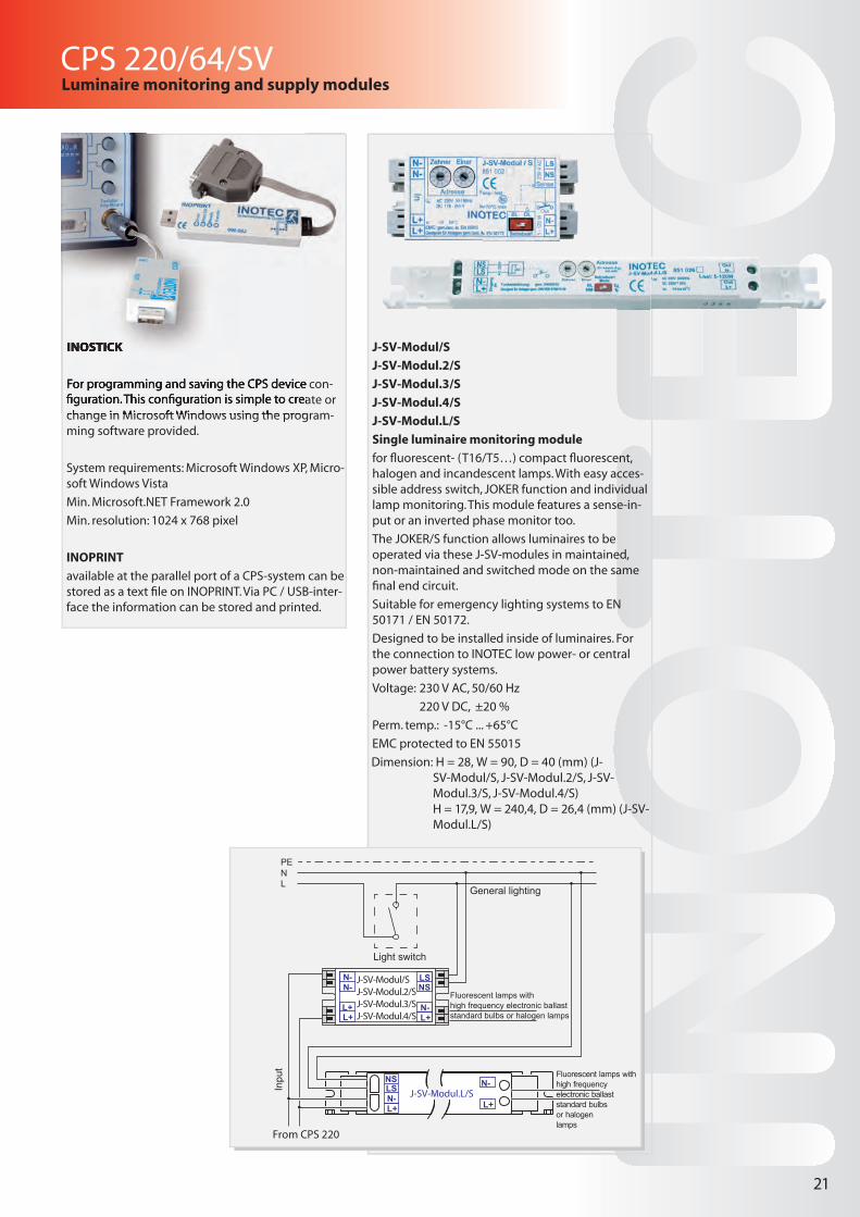
CPS 220/64/SV
21
Luminaire monitoring and supply modules
J-SV-Modul/S
J-SV-Modul.2/S
J-SV-Modul.3/S
J-SV-Modul.4/S
J-SV-Modul.L/S
Single luminaire monitoring module
for fl uorescent- (T16/T5…) compact fl uorescent, halogen and incandescent lamps. With easy acces-sible address switch, JOKER function and individual lamp monitoring. This module features a sense-in-put or an inverted phase monitor too.
The JOKER/S function allows luminaires to be operated via these J-SV-modules in maintained, non-maintained and switched mode on the same fi nal end circuit.
Suitable for emergency lighting systems to EN 50171 / EN 50172.
Designed to be installed inside of luminaires. For the connection to INOTEC low power- or central power battery systems.
Voltage: 230 V AC, 50/60 Hz
220 V DC, ±20 %
Perm. temp.: -15°C ... +65°C
EMC protected to EN 55015
Dimension: H = 28, W = 90, D = 40 (mm) (J-SV-Modul/S, J-SV-Modul.2/S, J-SV-Modul.3/S, J-SV-Modul.4/S)H = 17,9, W = 240,4, D = 26,4 (mm) (J-SV-Modul.L/S)
J-SV-Modul.L/SLSNS
N-L+
N-
L+
Inpu
t
Fluorescent lamps withhigh frequency electronic ballaststandard bulbs or halogen lamps
Fluorescent lamps withhigh frequency electronic ballaststandard bulbs or halogen lamps
Light switch
General lighting
PENL
N-N-
L+L+
J-SV-Modul/SJ-SV-Modul.2/SJ-SV-Modul.3/SJ-SV-Modul.4/S
LSNS
N-L+
From CPS 220
INOSTICK
For programming and saving the CPS device con-fi guration. This confi guration is simple to create or change in Microsoft Windows using the program-ming software provided.
System requirements: Microsoft Windows XP, Micro-soft Windows Vista
Min. Microsoft.NET Framework 2.0
Min. resolution: 1024 x 768 pixel
INOPRINT
available at the parallel port of a CPS-system can be stored as a text fi le on INOPRINT. Via PC / USB-inter-face the information can be stored and printed.
INOSTICK
For programming and saving the CPS device con-fi guration. This confi guration is simple to create or change in Microsoft Windows using the program-
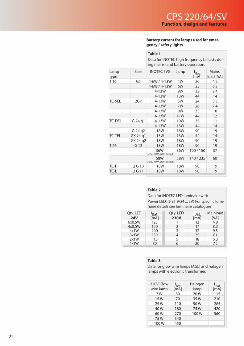
Table 1
Data for INOTEC high frequency ballasts dur-ing mains- and battery operation.
Battery current for lamps used for emer-gency / safety lights
Table 2
Data for INOTEC LED luminaire with
Power LED. (J-ET 9/24 ... SV) For specific lumi-naire details see luminaire catalogues.
Table 3
Data for glow wire lamps (AGL) and halogen lamps with electronic transformer.
22
Lamp Base INOTEC EVG Lamp IBat. Mains type [mA] load [VA]T 16 G5 4-6W / 4-13W 4W 20 4,2 4-6W / 4-13W 6W 25 6,3 4-13W 8W 33 8,4 4-13W 13W 44 14TC-SEL 2G7 4-13W 5W 24 5,3 4-13W 7W 26 7,4 4-13W 9W 33 10 4-13W 11W 44 12TC-DEL G 24 q1 4-13W 10W 35 11 4-13W 13W 44 14
G 24 q2 18W 18W 90 19TC-TEL GX 24 q1 13W 13W 44 14 GX 24 q2 18W 18W 90 19T 26 G 13 18W 18W 90 19 36W 36W 100 / 150 37 (50% / 100% Light output)
58W 58W 140 / 235 60(50% / 100% Light output)
TC-F 2 G 10 18W 18W 90 19TC-L 2 G 11 18W 18W 90 19
CPS 220/64/SVFunction, design and features
Qty. LED 24V
IBat. [mA]
6x0,5W 1254x0,5W 1004x1W 2003x1W 1502x1W 1151x1W 80
Qty. LED 230V
IBat. [mA]
Mainload [VA]
1 12 4,82 17 8,33 32 9,54 25 815 18 6,36 20 7,2
220V Glow IBat. Halogen IBat.wire lamp [mA] lamp [mA]
7 W 30 20 W 115 15 W 70 35 W 210 25 W 110 50 W 285 40 W 180 75 W 420
60 W 270 100 W 56075 W 340
100 W 450
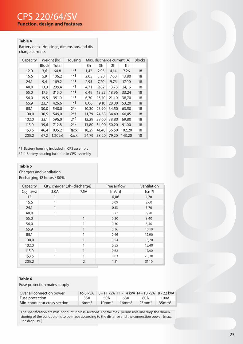
Table 4
Battery data Housings, dimensions and dis-charge currents
*1 Battery housing included in CPS assembly
*2 1 Battery housing included in CPS assembly
Table 5
Chargers and ventilation
Recharging 12 hours / 80%
Table 6
Fuse protection mains supply
The specification are min. conductur cross-sections. For the max. permissible line drop the dimen-sioning of the conductor is to be made according to the distance and the connection power. (max.line drop: 3%)
CPS 220/64/SVFunction, design and features
Qty. LED 230V
IBat. [mA]
Mainload [VA]
1 12 4,82 17 8,33 32 9,54 25 815 18 6,36 20 7,2
23
Over all connection power to 8 kVA 8 - 11 kVA 11 - 14 kVA 14 - 18 kVA 18 - 22 kVAFuse protection 35A 50A 63A 80A 100AMin. conductur cross-section 6mm² 10mm² 16mm² 25mm² 35mm²
Capacity Weight [kg] Housing Max. discharge current [A] BlocksBlock Total 8h 3h 2h 1h
12,0 3,6 64,8 1*1 1,42 2,95 4,14 7,26 1816,6 5,9 106,2 1*1 2,05 5,20 7,60 13,80 1824,1 9,4 169,2 1*1 2,95 7,20 9,76 17,00 1840,0 13,3 239,4 1*1 4,71 9,82 13,78 24,16 1855,0 17,5 315,0 1*1 6,49 13,52 18,96 33,24 1856,0 19,5 351,0 1*1 6,70 15,70 21,40 38,70 1865,9 23,7 426,6 1*1 8,06 19,10 28,30 53,20 1885,1 30,0 540,0 2*2 10,30 23,90 34,50 63,50 18
100,0 30,5 549,0 2*2 11,79 24,58 34,49 60,45 18102,0 33,1 596,0 2*2 12,29 28,60 38,80 69,80 18115,0 39,6 712,8 2*2 13,80 34,00 50,20 91,00 18153,6 46,4 835,2 Rack 18,29 41,40 56,50 102,20 18205,2 67,2 1.209,6 Rack 24,79 58,20 79,20 143,20 18
Capacity Qty. charger (3h- discharge) Free airflow VentilationC10-1,8V/Z 3,0A 7,5A [m³/h] [cm²]
12 1 0,06 1,70
16,6 1 0,09 2,60
24,1 1 0,13 3,70
40,0 1 0,22 6,20
55,0 1 0,30 8,40
56,0 1 0,30 8,40
65,9 1 0,36 10,10
85,1 1 0,46 12,90
100,0 1 0,54 15,20
102,0 1 0,55 15,40
115,0 1 1 0,62 17,40
153,6 1 1 0,83 23,30
205,2 2 1,11 31,10
24
INOTEC Sicherheitstechnik GmbHAm Buschgarten 17
D - 59 469 Ense
Tel +49 29 38/97 30-0 Fax +49 29 38/97 30-29
707
075
0
1/20
11
Sicherheitstechnik GmbH