Centering Clamping Fixture 80 - 21838...The centering clamping fixture is a complete clamping...
23
Original Installation and Operating Instructions Centering Clamping Fixture 80 - 21838
Transcript of Centering Clamping Fixture 80 - 21838...The centering clamping fixture is a complete clamping...
O r i g i n a l I n s t a l l a t i o n a n d O p e r a t i n g I n s t r u c t i o n s
Centering Clamping Fixture 80 - 21838

Copyright ZEROCLAMP® Centering Clamping Fixture 21838 Installation and Operating Instructions. These operating instructions are the property of ZeroClamp® GmbH, D-82057 Icking Unauthorized reproduction, even of extracts, is not permitted. Issue: 3/29/2017
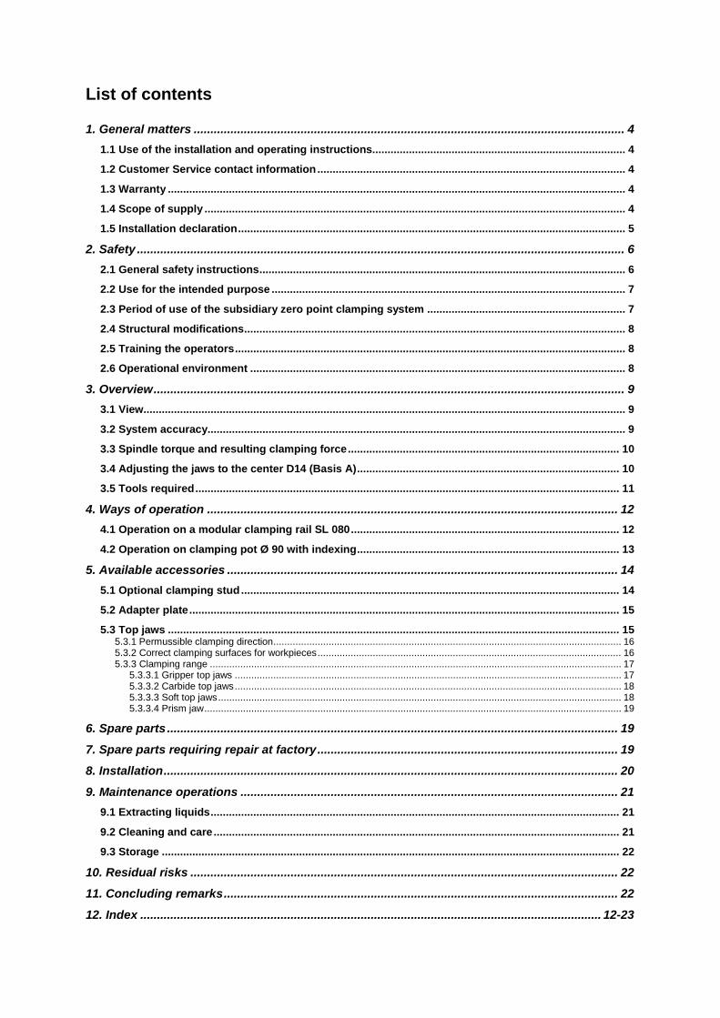
List of contents
1. General matters ................................................................................................................................. 4
1.1 Use of the installation and operating instructions ................................................................................... 4
1.2 Customer Service contact information ..................................................................................................... 4
1.3 Warranty ...................................................................................................................................................... 4
1.4 Scope of supply .......................................................................................................................................... 4
1.5 Installation declaration ............................................................................................................................... 5
2. Safety .................................................................................................................................................. 6
2.1 General safety instructions ........................................................................................................................ 6
2.2 Use for the intended purpose .................................................................................................................... 7
2.3 Period of use of the subsidiary zero point clamping system ................................................................. 7
2.4 Structural modifications ............................................................................................................................. 8
2.5 Training the operators ................................................................................................................................ 8
2.6 Operational environment ........................................................................................................................... 8
3. Overview ............................................................................................................................................. 9
3.1 View .............................................................................................................................................................. 9
3.2 System accuracy......................................................................................................................................... 9
3.3 Spindle torque and resulting clamping force ......................................................................................... 10
3.4 Adjusting the jaws to the center D14 (Basis A) ...................................................................................... 10
3.5 Tools required ........................................................................................................................................... 11
4. Ways of operation ........................................................................................................................... 12
4.1 Operation on a modular clamping rail SL 080 ........................................................................................ 12
4.2 Operation on clamping pot Ø 90 with indexing ...................................................................................... 13
5. Available accessories ..................................................................................................................... 14
5.1 Optional clamping stud ............................................................................................................................ 14
5.2 Adapter plate ............................................................................................................................................. 15
5.3 Top jaws .................................................................................................................................................... 15 5.3.1 Permussible clamping direction .............................................................................................................................. 16 5.3.2 Correct clamping surfaces for workpieces .............................................................................................................. 16 5.3.3 Clamping range ..................................................................................................................................................... 17
5.3.3.1 Gripper top jaws ............................................................................................................................................ 17 5.3.3.2 Carbide top jaws ............................................................................................................................................ 18 5.3.3.3 Soft top jaws .................................................................................................................................................. 18 5.3.3.4 Prism jaw ....................................................................................................................................................... 19
6. Spare parts ....................................................................................................................................... 19
7. Spare parts requiring repair at factory .......................................................................................... 19
8. Installation ........................................................................................................................................ 20
9. Maintenance operations ................................................................................................................. 21
9.1 Extracting liquids ...................................................................................................................................... 21
9.2 Cleaning and care ..................................................................................................................................... 21
9.3 Storage ...................................................................................................................................................... 22
10. Residual risks ................................................................................................................................ 22
11. Concluding remarks ...................................................................................................................... 22
12. Index .......................................................................................................................................... 12-23
General matters
ZeroClamp Centering Clamping Fixture Operating Instructions 4
1. General matters
1.1 Use of the installation and operating instructions Dear customer, Many thanks for deciding to purchase our products. These installation and operating instructions contain useful information allowing you to familiarize yourself with your clamping system before starting to use it for its intended purpose under the specified operating conditions. They contain important instructions to ensure functionally correct and cost-effective installation and operation. The operating instructions have been created for use by installation, operating and maintenance staff, and must always be kept to hand at the place of use of the clamping system. You have chosen a high-quality clamping system which operates at extremely high precision. In the interests of product improvement we reserve the right to make changes in respect of versions, dimensions and materials. Of course, we remain available to you at all times for after-sales service. Please contact us using the information set out below.
1.2 Customer Service contact information ZeroClamp GmbH Wadlhausen 14 D-82057 Icking Tel. +49 (0) 8178-90998-0 [email protected]
1.3 Warranty The warranty is 12 months from the date of delivery from the works, provided the system is used for its intended purpose in 1-shift operation. These operating instructions supersede any previous versions. The current version of operating instructions is available for download at www.zeroclamp.com
1.4 Scope of supply The scope of supply includes:
• Main body centering clamping fixture (1x) • Stop bars (2x) + corresponding Torx screws M3x6 TX (2x each) • Clamping bracket (2x) • Socket E12 (1x)
General matters
ZeroClamp Centering Clamping Fixture Operating Instructions 5
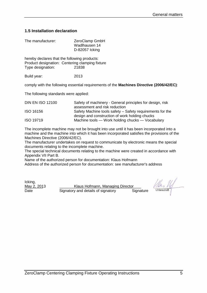
1.5 Installation declaration The manufacturer: ZeroClamp GmbH Wadlhausen 14 D-82057 Icking hereby declares that the following products: Product designation: Centering clamping fixture Type designation: 21838 Build year: 2013 comply with the following essential requirements of the Machines Directive (2006/42/EC): The following standards were applied: DIN EN ISO 12100 Safety of machinery - General principles for design, risk
assessment and risk reduction ISO 16156 Safety Machine tools safety – Safety requirements for the
design and construction of work holding chucks ISO 19719 Machine tools — Work holding chucks — Vocabulary The incomplete machine may not be brought into use until it has been incorporated into a machine and the machine into which it has been incorporated satisfies the provisions of the Machines Directive (2006/42/EC). The manufacturer undertakes on request to communicate by electronic means the special documents relating to the incomplete machine. The special technical documents relating to the machine were created in accordance with Appendix VII Part B. Name of the authorized person for documentation: Klaus Hofmann Address of the authorized person for documentation: see manufacturer's address Icking, May 2, 2013 Klaus Hofmann, Managing Director Date Signatory and details of signatory Signature
Safety
ZeroClamp Centering Clamping Fixture Operating Instructions 6
2. Safety
2.1 General safety instructions
Warning! When using the centering clamping fixture on NP90
If the forces acting on the centering clamping fixture become too great due to machining of a workpiece, the clamping stud might be torn from the clamping pot even in the clamped state. Do not overload the zero point clamping system. Make an estimate of the forces to be expected. Use additional safety devices, e.g., monitoring devices, feeder devices and safety guards.
Warning! When using the centering clamping fixture on NP90
The zero point clamping system will only clamp the centering clamping fixture reliably if the clamping stud and the clamping pot lie flat against each other. Even slight impurities between the contact surfaces, or a tilted position will compromise the clamping effect. Furthermore, surface inaccuracies caused by wear will also compromise the clamping effect. Before clamping the pieces, always thoroughly clean the contact surfaces between clamping stud and clamping pot! Verify the exact concentric alignment of clamping stud and clamping pot. Regularly check the clamping force of the zero point clamping system, using a pull-out force tester. Use the subsidiary zero point clamping system for a maximum of 1000000 clamping cycles.
Warning!
When the centering clamping fixture is actuated, the skin of the fingers or the fingers might be crushed at the clamping jaws. During the clamping operation, do not reach between the clamping jaws, or between the clamping jaw and the workpiece.
Safety
ZeroClamp Centering Clamping Fixture Operating Instructions 7
Warning! When using the centering clamping fixture on NP90
Accidental actuation of the subsidiary zero point clamping system might lead to unintentional releasing of the clamping assembly. Disconnect the zero point clamping system from the compressed air supply before you undertake installation, adjustment, maintenance or set-up work. During operation, secure the subsidiary zero point clamping system against unintentional releasing by using suitable safety devices for the compressed air supply.
Warning!
Clamping systems made up of multiple centering clamping fixtures arranged in a row can be extremely heavy. When you build your own clamping assemblies, make sure that they can be fastened in a suitable way in order to be lifted with handling devices or cranes. Give particular attention to this point if the clamping systems weigh 20 kg and more.
2.2 Use for the intended purpose
The clamping system must only be used for clamping workpieces.
Use for the intended purpose includes compliance with the conditions specified by the manufacturer in respect of installation, commissioning, operation, ambient conditions and maintenance.
Any use that is not within these conditions ranks as improper use. The manufacturer accepts no responsibility for damage resulting from improper use. Before using the clamping system in an environment with abrasive dusts, caustic or aggressive vapors or liquids, you must obtain approval by ZeroClamp®.
2.3 Period of use of the subsidiary zero point clamping system The zero point clamping system mechanism is designed for a maximum life span of 1,000,000 clamping cycles.
Safety
ZeroClamp Centering Clamping Fixture Operating Instructions 8
2.4 Structural modifications For reasons of safety, unauthorized changes and modifications of the centering clamping fixture are prohibited. When exchanging defective parts, use only original parts or standard parts that are approved by the manufacturer.
2.5 Training the operators The operators must have received instruction on the following topics: • Functionality and operation of the centering clamping fixture • Servicing and cleaning work All persons responsible for the installation, commissioning and maintenance of the tester must have read and understood the complete operating instructions, especially Section 2 "Safety". We recommend that the operating company obtains signatures to this effect. Installation, removal, connection and commissioning may be performed only by authorized personnel. Do not use operating techniques which adversely affect the functionality and operational safety of the clamping system.
2.6 Operational environment The centering clamping fixture is not suitable for the following operational environments:
• Abrasive dusts, • Caustic or aggressive liquids and vapors.
Overview
ZeroClamp Centering Clamping Fixture Operating Instructions 9
3. Overview 3.1 View
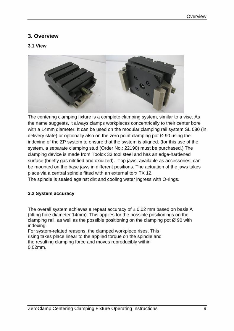
The centering clamping fixture is a complete clamping system, similar to a vise. As the name suggests, it always clamps workpieces concentrically to their center bore with a 14mm diameter. It can be used on the modular clamping rail system SL 080 (in delivery state) or optionally also on the zero point clamping pot Ø 90 using the indexing of the ZP system to ensure that the system is aligned. (for this use of the system, a separate clamping stud (Order No.: 22190) must be purchased.) The clamping device is made from Toolox 33 tool steel and has an edge-hardened surface (briefly gas nitrified and oxidized). Top jaws, available as accessories, can be mounted on the base jaws in different positions. The actuation of the jaws takes place via a central spindle fitted with an external torx TX 12. The spindle is sealed against dirt and cooling water ingress with O-rings.
3.2 System accuracy
The overall system achieves a repeat accuracy of ± 0.02 mm based on basis A (fitting hole diameter 14mm). This applies for the possible positionings on the clamping rail, as well as the possible positioning on the clamping pot Ø 90 with indexing. For system-related reasons, the clamped workpiece rises. This rising takes place linear to the applied torque on the spindle and the resulting clamping force and moves reproducibly within 0.02mm.
Overview
ZeroClamp Centering Clamping Fixture Operating Instructions 10
3.3 Spindle torque and resulting clamping force A max. torque of 40 Nm can be applied on the spindle. This results in a minimum clamping force of 17kN on the jaws. However, the clamping force might also be greater, depending on tolerances and friction within the system. The force progression is linear to the applied torque. A TX socket inside, size E12, is required for this.
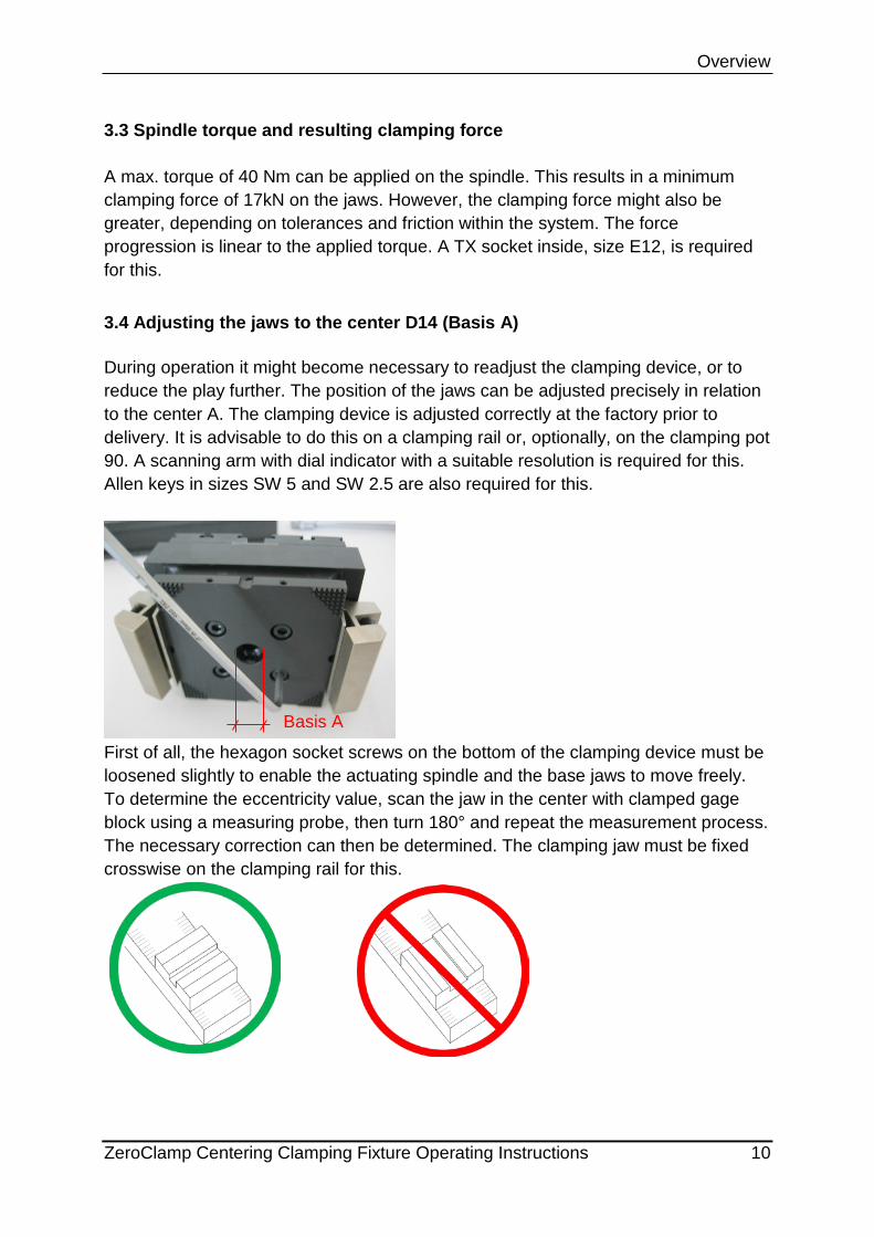
3.4 Adjusting the jaws to the center D14 (Basis A) During operation it might become necessary to readjust the clamping device, or to reduce the play further. The position of the jaws can be adjusted precisely in relation to the center A. The clamping device is adjusted correctly at the factory prior to delivery. It is advisable to do this on a clamping rail or, optionally, on the clamping pot 90. A scanning arm with dial indicator with a suitable resolution is required for this. Allen keys in sizes SW 5 and SW 2.5 are also required for this.
First of all, the hexagon socket screws on the bottom of the clamping device must be loosened slightly to enable the actuating spindle and the base jaws to move freely. To determine the eccentricity value, scan the jaw in the center with clamped gage block using a measuring probe, then turn 180° and repeat the measurement process. The necessary correction can then be determined. The clamping jaw must be fixed crosswise on the clamping rail for this.
Basis A
Overview
ZeroClamp Centering Clamping Fixture Operating Instructions 11
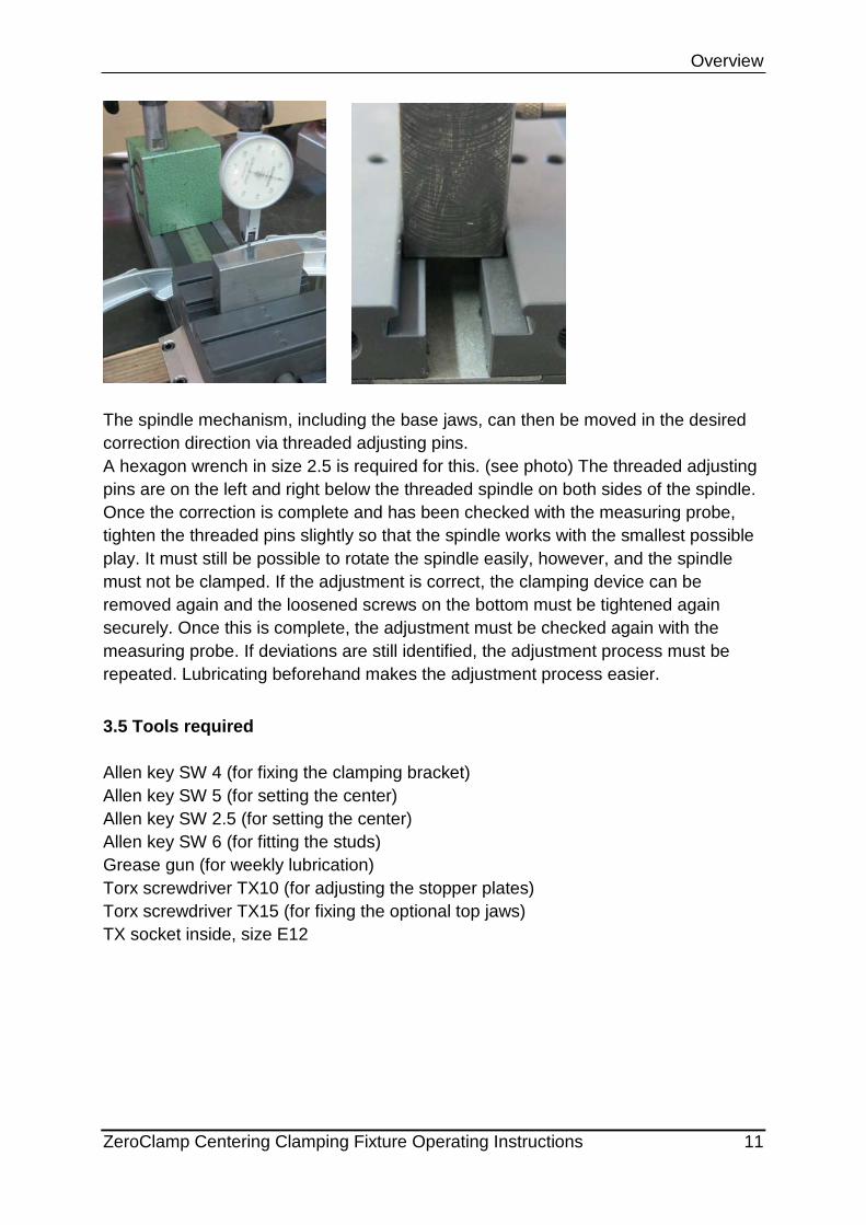
The spindle mechanism, including the base jaws, can then be moved in the desired correction direction via threaded adjusting pins. A hexagon wrench in size 2.5 is required for this. (see photo) The threaded adjusting pins are on the left and right below the threaded spindle on both sides of the spindle. Once the correction is complete and has been checked with the measuring probe, tighten the threaded pins slightly so that the spindle works with the smallest possible play. It must still be possible to rotate the spindle easily, however, and the spindle must not be clamped. If the adjustment is correct, the clamping device can be removed again and the loosened screws on the bottom must be tightened again securely. Once this is complete, the adjustment must be checked again with the measuring probe. If deviations are still identified, the adjustment process must be repeated. Lubricating beforehand makes the adjustment process easier.
3.5 Tools required
Allen key SW 4 (for fixing the clamping bracket) Allen key SW 5 (for setting the center) Allen key SW 2.5 (for setting the center) Allen key SW 6 (for fitting the studs) Grease gun (for weekly lubrication) Torx screwdriver TX10 (for adjusting the stopper plates) Torx screwdriver TX15 (for fixing the optional top jaws) TX socket inside, size E12
Ways of operation
ZeroClamp Centering Clamping Fixture Operating Instructions 12
4. Ways of operation
4.1 Operation on a modular clamping rail SL 080
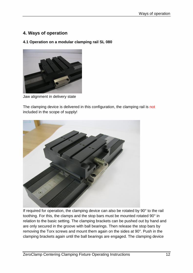
Jaw alignment in delivery state The clamping device is delivered in this configuration, the clamping rail is not included in the scope of supply!
If required for operation, the clamping device can also be rotated by 90° to the rail toothing. For this, the clamps and the stop bars must be mounted rotated 90° in relation to the basic setting. The clamping brackets can be pushed out by hand and are only secured in the groove with ball bearings. Then release the stop bars by removing the Torx screws and mount them again on the sides at 90°. Push in the clamping brackets again until the ball bearings are engaged. The clamping device
Ways of operation
ZeroClamp Centering Clamping Fixture Operating Instructions 13
can now be placed on the clamping rail again. To guarantee secure fixing, both screws (SW 4) of each clamping bracket must be tightened with 10 Nm each.
A Torx screwdriver size TX10 is required for this.
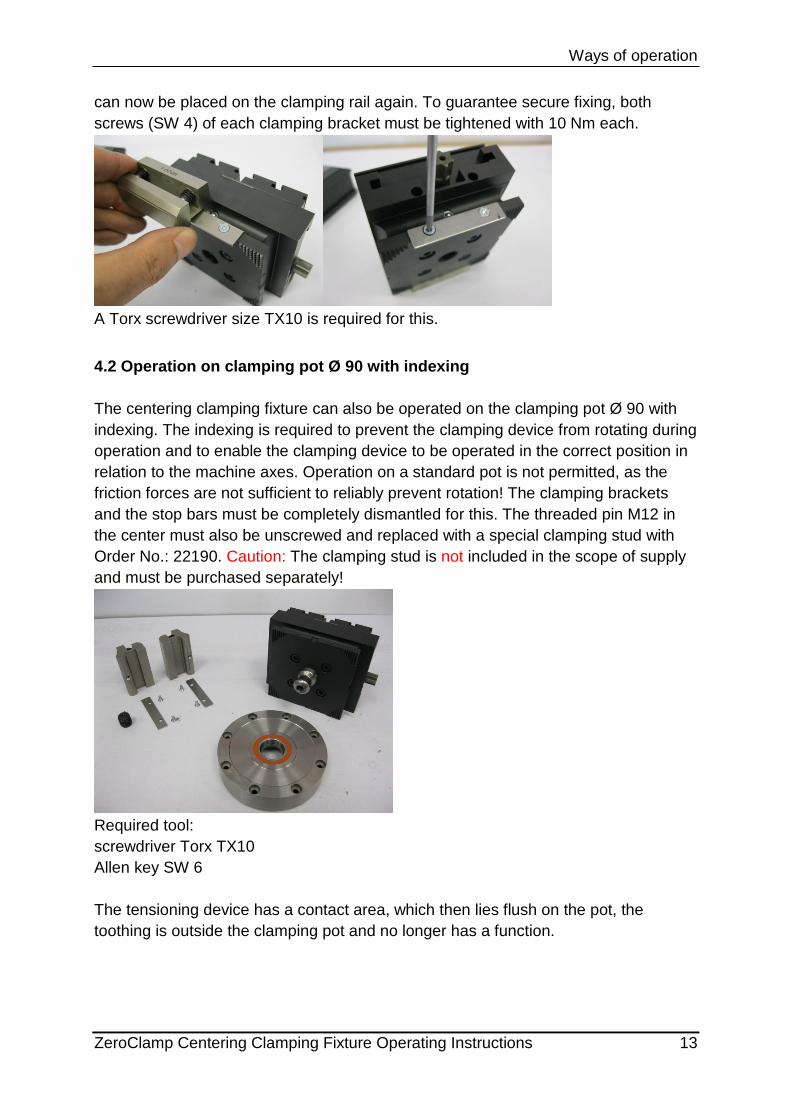
4.2 Operation on clamping pot Ø 90 with indexing The centering clamping fixture can also be operated on the clamping pot Ø 90 with indexing. The indexing is required to prevent the clamping device from rotating during operation and to enable the clamping device to be operated in the correct position in relation to the machine axes. Operation on a standard pot is not permitted, as the friction forces are not sufficient to reliably prevent rotation! The clamping brackets and the stop bars must be completely dismantled for this. The threaded pin M12 in the center must also be unscrewed and replaced with a special clamping stud with Order No.: 22190. Caution: The clamping stud is not included in the scope of supply and must be purchased separately!
Required tool: screwdriver Torx TX10 Allen key SW 6 The tensioning device has a contact area, which then lies flush on the pot, the toothing is outside the clamping pot and no longer has a function.
Available accessories
ZeroClamp Centering Clamping Fixture Operating Instructions 14
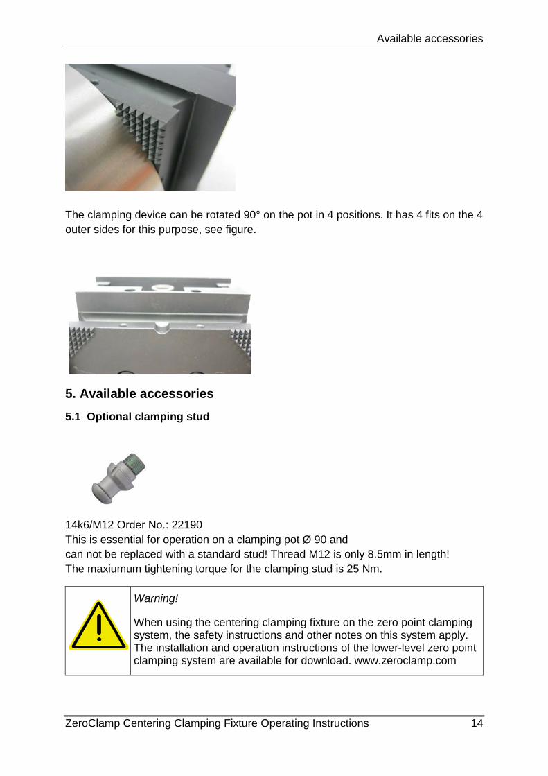
The clamping device can be rotated 90° on the pot in 4 positions. It has 4 fits on the 4 outer sides for this purpose, see figure.
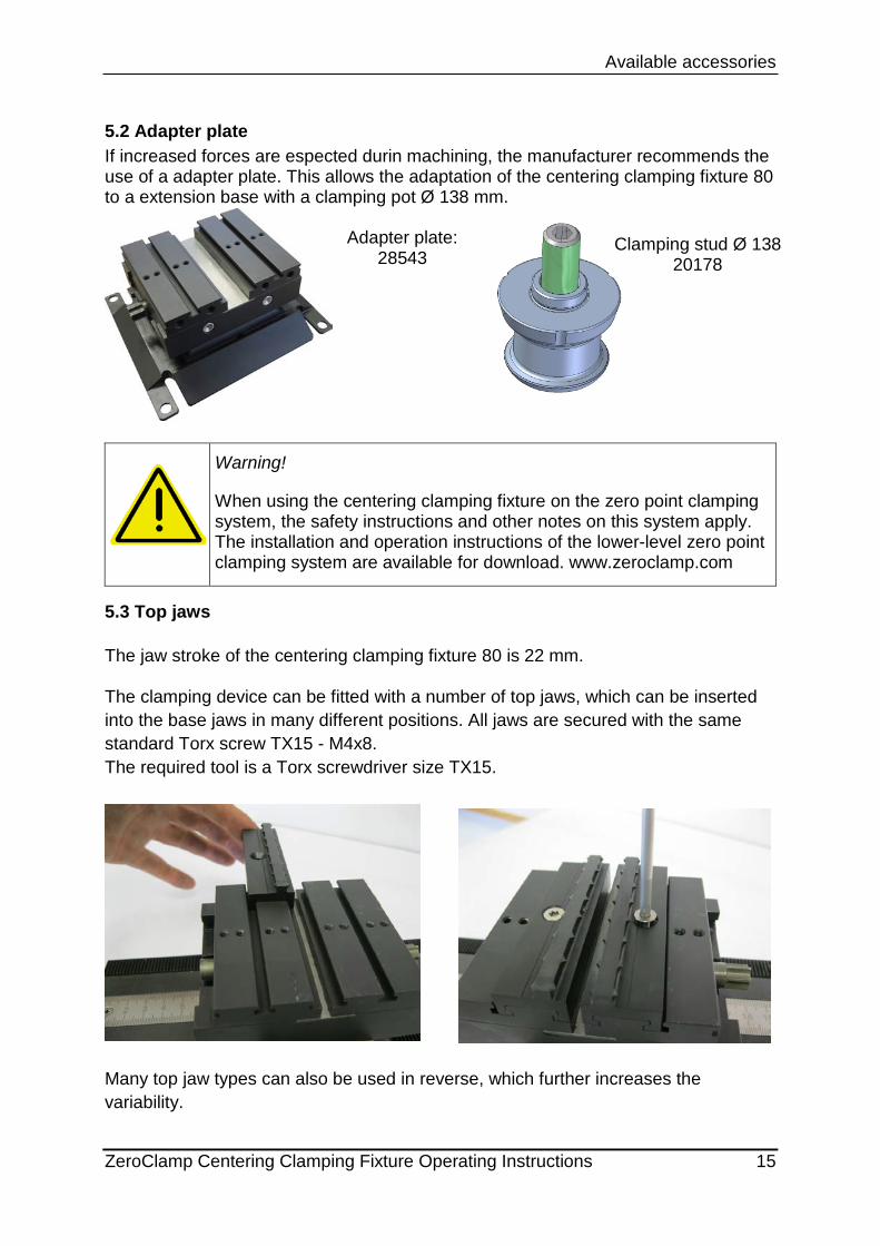
5. Available accessories 5.1 Optional clamping stud
14k6/M12 Order No.: 22190 This is essential for operation on a clamping pot Ø 90 and can not be replaced with a standard stud! Thread M12 is only 8.5mm in length! The maxiumum tightening torque for the clamping stud is 25 Nm.
Warning!
When using the centering clamping fixture on the zero point clamping system, the safety instructions and other notes on this system apply. The installation and operation instructions of the lower-level zero point clamping system are available for download. www.zeroclamp.com
Available accessories
ZeroClamp Centering Clamping Fixture Operating Instructions 15
5.2 Adapter plate If increased forces are espected durin machining, the manufacturer recommends the use of a adapter plate. This allows the adaptation of the centering clamping fixture 80 to a extension base with a clamping pot Ø 138 mm.
Warning!
When using the centering clamping fixture on the zero point clamping system, the safety instructions and other notes on this system apply. The installation and operation instructions of the lower-level zero point clamping system are available for download. www.zeroclamp.com
5.3 Top jaws The jaw stroke of the centering clamping fixture 80 is 22 mm. The clamping device can be fitted with a number of top jaws, which can be inserted into the base jaws in many different positions. All jaws are secured with the same standard Torx screw TX15 - M4x8. The required tool is a Torx screwdriver size TX15.
Many top jaw types can also be used in reverse, which further increases the variability.
Adapter plate: 28543
Clamping stud Ø 138 20178
Available accessories
ZeroClamp Centering Clamping Fixture Operating Instructions 16
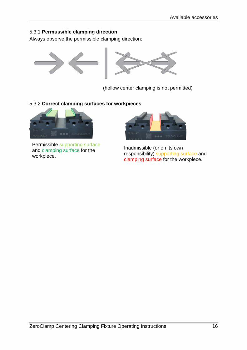
5.3.1 Permussible clamping direction Always observe the permissible clamping direction:
(hollow center clamping is not permitted)
5.3.2 Correct clamping surfaces for workpieces
Permissible supporting surface and clamping surface for the workpiece.
Inadmissible (or on its own responsibility) supporting surface and clamping surface for the workpiece.
Available accessories
ZeroClamp Centering Clamping Fixture Operating Instructions 17
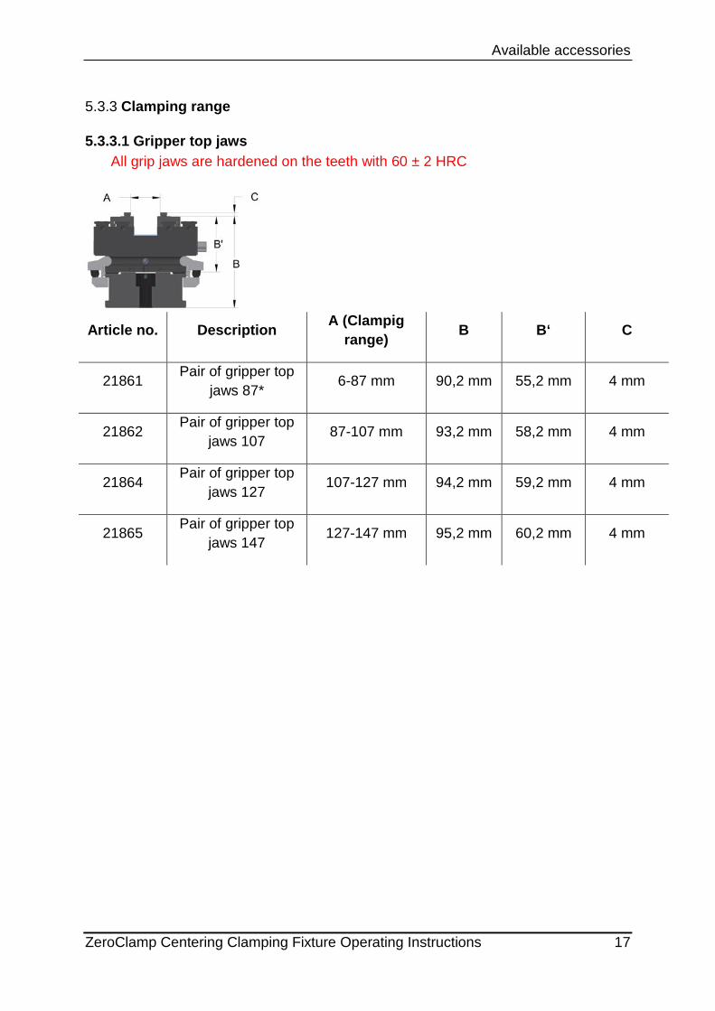
5.3.3 Clamping range
5.3.3.1 Gripper top jaws All grip jaws are hardened on the teeth with 60 ± 2 HRC
Article no. Description A (Clampig
range) B B‘ C
21861 Pair of gripper top jaws 87* 6-87 mm 90,2 mm 55,2 mm 4 mm
21862 Pair of gripper top jaws 107 87-107 mm 93,2 mm 58,2 mm 4 mm
21864 Pair of gripper top jaws 127 107-127 mm 94,2 mm 59,2 mm 4 mm
21865 Pair of gripper top jaws 147 127-147 mm 95,2 mm 60,2 mm 4 mm
Available accessories
ZeroClamp Centering Clamping Fixture Operating Instructions 18
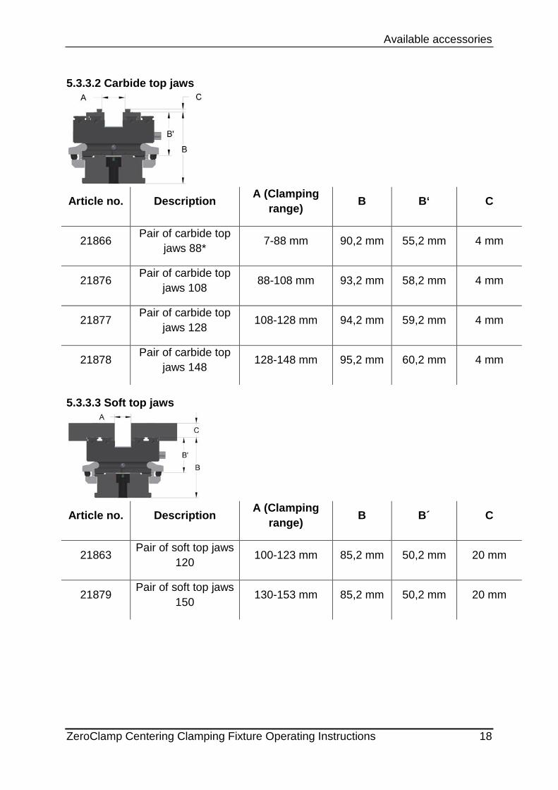
5.3.3.2 Carbide top jaws
Article no. Description A (Clamping
range) B B‘ C
21866 Pair of carbide top jaws 88* 7-88 mm 90,2 mm 55,2 mm 4 mm
21876 Pair of carbide top jaws 108 88-108 mm 93,2 mm 58,2 mm 4 mm
21877 Pair of carbide top jaws 128 108-128 mm 94,2 mm 59,2 mm 4 mm
21878 Pair of carbide top jaws 148 128-148 mm 95,2 mm 60,2 mm 4 mm
5.3.3.3 Soft top jaws
Article no. Description A (Clamping
range) B B´ C
21863 Pair of soft top jaws 120 100-123 mm 85,2 mm 50,2 mm 20 mm
21879 Pair of soft top jaws 150 130-153 mm 85,2 mm 50,2 mm 20 mm
Spare parts
ZeroClamp Centering Clamping Fixture Operating Instructions 19
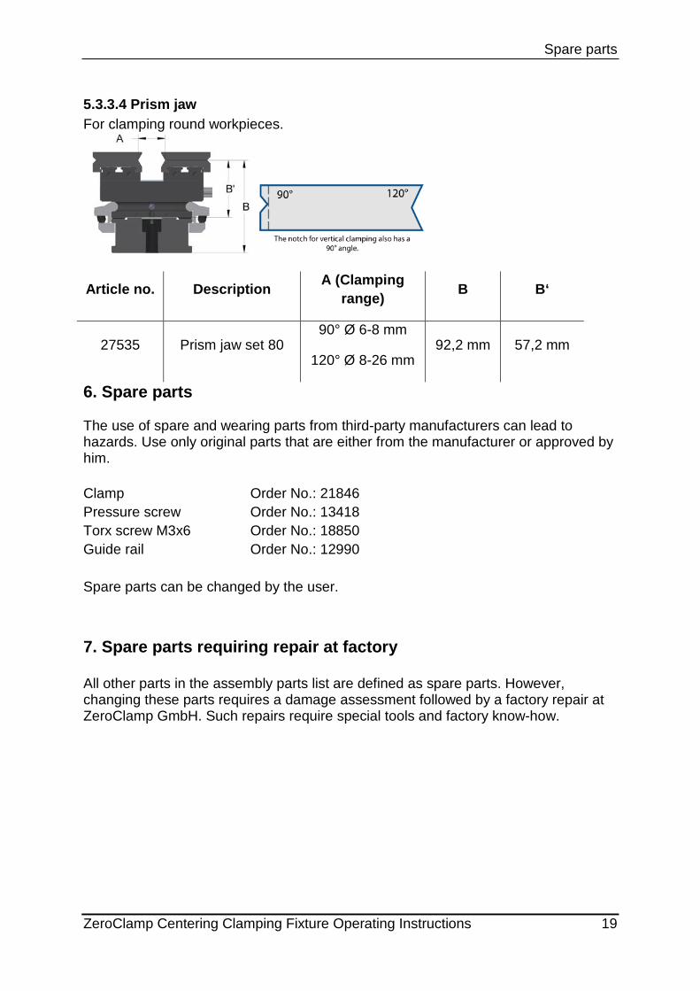
5.3.3.4 Prism jaw For clamping round workpieces.
Article no. Description A (Clamping range) B B‘
27535 Prism jaw set 80 90° Ø 6-8 mm
120° Ø 8-26 mm 92,2 mm 57,2 mm
6. Spare parts The use of spare and wearing parts from third-party manufacturers can lead to hazards. Use only original parts that are either from the manufacturer or approved by him. Clamp Order No.: 21846 Pressure screw Order No.: 13418 Torx screw M3x6 Order No.: 18850 Guide rail Order No.: 12990 Spare parts can be changed by the user.
7. Spare parts requiring repair at factory All other parts in the assembly parts list are defined as spare parts. However, changing these parts requires a damage assessment followed by a factory repair at ZeroClamp GmbH. Such repairs require special tools and factory know-how.
Installation
ZeroClamp Centering Clamping Fixture Operating Instructions 20
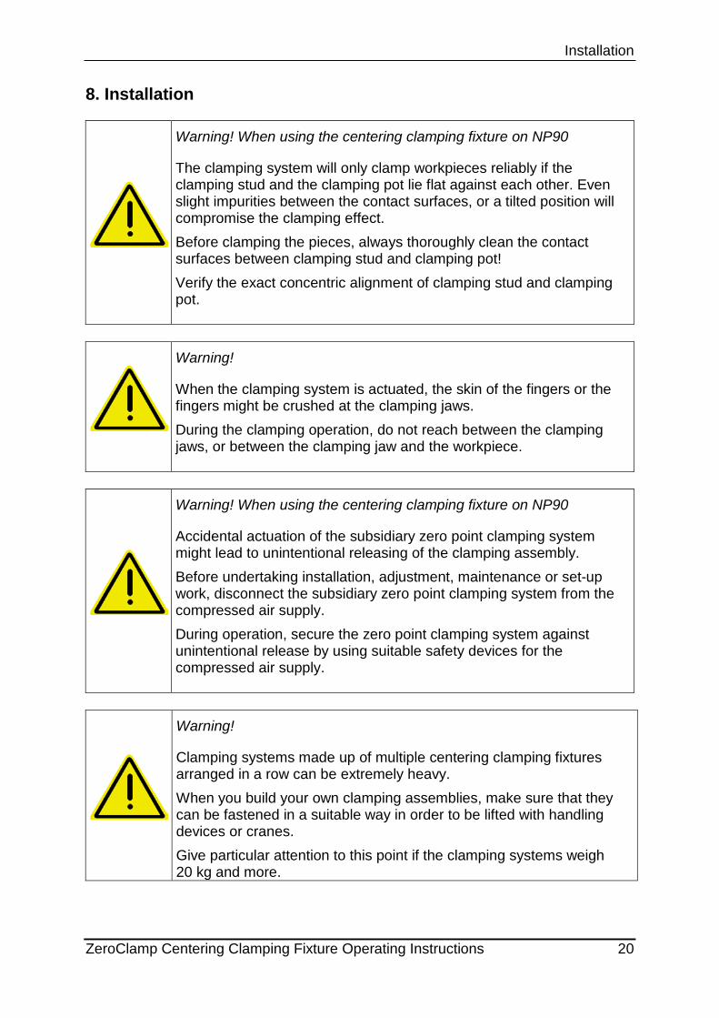
8. Installation
Warning! When using the centering clamping fixture on NP90
The clamping system will only clamp workpieces reliably if the clamping stud and the clamping pot lie flat against each other. Even slight impurities between the contact surfaces, or a tilted position will compromise the clamping effect. Before clamping the pieces, always thoroughly clean the contact surfaces between clamping stud and clamping pot! Verify the exact concentric alignment of clamping stud and clamping pot.
Warning!
When the clamping system is actuated, the skin of the fingers or the fingers might be crushed at the clamping jaws. During the clamping operation, do not reach between the clamping jaws, or between the clamping jaw and the workpiece.
Warning! When using the centering clamping fixture on NP90
Accidental actuation of the subsidiary zero point clamping system might lead to unintentional releasing of the clamping assembly. Before undertaking installation, adjustment, maintenance or set-up work, disconnect the subsidiary zero point clamping system from the compressed air supply. During operation, secure the zero point clamping system against unintentional release by using suitable safety devices for the compressed air supply.
Warning!
Clamping systems made up of multiple centering clamping fixtures arranged in a row can be extremely heavy. When you build your own clamping assemblies, make sure that they can be fastened in a suitable way in order to be lifted with handling devices or cranes. Give particular attention to this point if the clamping systems weigh 20 kg and more.

Care and Servicing
ZeroClamp Centering Clamping Fixture Operating Instructions 21
9. Maintenance operations The clamping device is very easy to maintain. Only once a week, lightly grease the internal mechanism. For this purpose, there are lateral grease nipples. Grease with a grease gun and HPL-15 (see 9.2). 2 or 3 strokes are sufficient. Wipe off excessive or escaping grease with a cloth. Then actuate the clamping mechanism several times.
9.1 Extracting liquids For extracting liquids, you can use commercially available extraction devices.
9.2 Cleaning and care Approved cleaning and care agents:
• WD 40 • Ballistol • Hebro Multiplus
Lubricating paste to be used:
• ZERO CLAMP HPL-15 (Order No.: 27779) incl. tip o Refill cartridge (Order No.: 27212)
Prohibited cleaning and care agents:
• Acids • Lyes • aggressive media • not approved cleaning and care agents
Care and Servicing
ZeroClamp Centering Clamping Fixture Operating Instructions 22
9.3 Storage Before storage, the manufacturer recommends to clean the clamping device thoroughly, and to oil or grease all surfaces and the clamping mechanism. 10. Residual risks
Description of risk
Minimization of risk
Disregard of safety instructions
Training the staff about the hazards
11. Concluding remarks
The product is subject to continuous further development, and ZeroClamp GmbH reserves the right to make technical changes. Wherever possible, these will be compatible with previous versions. The portfolio of accessories is also being constantly expanded and complemented.
General instruction
When using the centering clamping fixture on NP90, observe in addition all safety instructions and other instructions regarding NP90. The installation and operating instructions of the subsidiary zero point clamping system are available for download. www.zeroclamp.com
Index
ZeroClamp Centering Clamping Fixture Operating Instructions 12-23
12. Index
A
Accessories ...................................... 14 Accuracy ............................................. 9
C
Carbide jaw ................................. 16, 18 Care .................................................. 23 Clamping force ................................. 10 Cleaning ........................................... 23 Cleaning agent ................................. 23 Customer Service contact information 4
E
Extracting liquids .............................. 23
G
General safety instructions ................. 6
I
Installation ........................................ 22 Installation declaration ........................ 5
J
Jaws ................................................. 15
M
Maintenance operations ................... 23 Modular clamping rail system SL080 12
O
Operational environment .................... 8
P
Period of use ...................................... 7
R
Repair at factory .............................. 21 Residual risks .................................. 24
S
Safety ................................................ 6 Scope of supply ................................. 4 Soft jaw ............................................ 20 Spare parts ...................................... 21 Storage ............................................ 24 Structural measures ........................... 8 Stud ................................................. 14
T
Tools ................................................ 11 Training the operators ........................ 8
U
Use for the intended purpose............. 7 Use of the operating instructions ....... 4
W
Warranty ............................................ 4
Z
Zero point clamping system ............. 13