CENTERING AND FRICTION REDUCTION BETWEEN PARTS OF …
8
International Tribology Council The 10 th International Conference BALTTRIB'2019 Vytautas Magnus University 14–16 November 2019 Agriculture Academy Lithuanian Scientific Society Department “Tribologija” Akademija, Kaunas, Lithuania Proceedings of BALTTRIB’2019 edited by prof. J. Padgurskas ISSN 2424-5089 (Online) https://doi.org/10.15544/balttrib.2019.16 94 Copyright © 2019 The Authors. Published by Vytautas Magnus University. This is an open-access article distributed under the terms of the Creative Commons Attribution License (CC BY 4.0), which permits unrestricted use, distribution, and reproduction in any medium, provided the original author and source are credited. CENTERING AND FRICTION REDUCTION BETWEEN PARTS OF THE CYLINDER-PISTON GROUP Y. Kligerman 1 , I. Cohen, A. Shinkarenko Faculty of Mechanical Engineering, Technion – Israel Institute of Technology, Israel Abstract: The current study is devoted to the development of the relative motion model of the piston and cylinder liner. The piston and the cylinder liner may be parts of the internal combustion engine; plunger pump; piston compressor etc. The nominal radial clearance between the piston and the cylinder liner is very small, and is filled with viscous liquid or gas. The piston and cylinder performs a relative axial reciprocating motion in accordance with the predetermined law in time. Generally, the piston separates the "high" and "low" pressure areas. Therefore, the gap viscous liquid or gas are located between the eccentric moving walls in the presence of an axial pressure drop. The possible contact between the piston and the cylinder liner is a potential cause of the energy losses to friction and increased wear of the contacting parts. To reduce the damage from contact, it is desirable to achieve centering of the piston during its movement inside the cylinder liner. One way to achieve the centering of the piston is the profiling of it, which provides a supporting radial effect of the viscous liquid or gas. Keywords: surface texturing; hydrodynamic lubrication; reciprocating motion; energy losses. 1. INTRODUCTION Cylinder-piston group is widely used in various engineering applications. Among these are spool valves, internal combustion engines, plunger pumps, piston compressors, various actuators, capsule-pipeline transportation, viscometers, timing devices, free piston in some versions of the Stirling engine etc. In our study we consider ring-less piston-cylinder system, typical for plunger pumps, free piston in some versions of the Stirling engine etc. Such systems differ from the cylinder-piston group of the internal combustion engine that includes crankshaft, connecting rod, piston pin and piston rings. So, the main reason of the frictional contact between the piston and the cylinder liner is an instability of the piston in the transverse direction during its predetermined reciprocating motion in the axial direction. Motion of pistons in piston type hydraulic machines have been analyzed in the past, and it was observed both analytically (see e.g. [1]) and experimentally (see e.g. [2]) that the piston radial movement is unstable for many various system parameters and operation conditions; a piston may vibrate and hit the wall of the cylinder liner during each oscillation [3]. The eccentric running of the piston may lead to leakage increase by 1.5–2 times [4]. In addition, the eccentric running of the piston may cause friction between the piston and the cylinder liner, which seriously reduces the efficiency and life span of the cylinder-piston group. There are some publication analyzing the piston instability during its movement inside the cylinder liner and suggesting solutions for gaining stability, e.g. [5]. This study suggests a new way for centering piston using close loop control system with active magnetic control system. In order to reduce the damage from contact between the mating surfaces, it is desirable to achieve centering of the piston during its movement inside the cylinder liner. One way to achieve the centering of the piston is the profiling of the piston, which provides a supporting radial effect of the fluid or gas layer in the gap with the cylinder liner. 1 Author for contacts: Dr. Yuri Kligerman E–mail: [email protected]
Transcript of CENTERING AND FRICTION REDUCTION BETWEEN PARTS OF …

International Tribology Council The 10th International Conference BALTTRIB'2019
Vytautas Magnus University 14–16 November 2019
Agriculture Academy
Lithuanian Scientific Society Department “Tribologija” Akademija, Kaunas, Lithuania
Proceedings of BALTTRIB’2019 edited by prof. J. Padgurskas ISSN 2424-5089 (Online)
https://doi.org/10.15544/balttrib.2019.16
94
Copyright © 2019 The Authors. Published by Vytautas Magnus University. This is an open-access article distributed under the terms of the Creative Commons Attribution License (CC BY 4.0), which permits unrestricted use, distribution, and reproduction in any medium, provided the original author and source are credited.
CENTERING AND FRICTION REDUCTION BETWEEN PARTS OF
THE CYLINDER-PISTON GROUP
Y. Kligerman1, I. Cohen, A. Shinkarenko Faculty of Mechanical Engineering, Technion – Israel Institute of Technology, Israel
Abstract: The current study is devoted to the development of the relative motion model of the piston and cylinder
liner. The piston and the cylinder liner may be parts of the internal combustion engine; plunger pump; piston
compressor etc. The nominal radial clearance between the piston and the cylinder liner is very small, and is filled
with viscous liquid or gas. The piston and cylinder performs a relative axial reciprocating motion in accordance
with the predetermined law in time. Generally, the piston separates the "high" and "low" pressure areas. Therefore,
the gap viscous liquid or gas are located between the eccentric moving walls in the presence of an axial pressure
drop. The possible contact between the piston and the cylinder liner is a potential cause of the energy losses to
friction and increased wear of the contacting parts. To reduce the damage from contact, it is desirable to achieve
centering of the piston during its movement inside the cylinder liner. One way to achieve the centering of the piston
is the profiling of it, which provides a supporting radial effect of the viscous liquid or gas.
Keywords: surface texturing; hydrodynamic lubrication; reciprocating motion; energy losses.
1. INTRODUCTION
Cylinder-piston group is widely used in various engineering applications. Among these are spool valves,
internal combustion engines, plunger pumps, piston compressors, various actuators, capsule-pipeline
transportation, viscometers, timing devices, free piston in some versions of the Stirling engine etc.
In our study we consider ring-less piston-cylinder system, typical for plunger pumps, free piston in some
versions of the Stirling engine etc. Such systems differ from the cylinder-piston group of the internal
combustion engine that includes crankshaft, connecting rod, piston pin and piston rings. So, the main
reason of the frictional contact between the piston and the cylinder liner is an instability of the piston in
the transverse direction during its predetermined reciprocating motion in the axial direction.
Motion of pistons in piston type hydraulic machines have been analyzed in the past, and it was observed
both analytically (see e.g. [1]) and experimentally (see e.g. [2]) that the piston radial movement is
unstable for many various system parameters and operation conditions; a piston may vibrate and hit the
wall of the cylinder liner during each oscillation [3].
The eccentric running of the piston may lead to leakage increase by 1.5–2 times [4]. In addition, the
eccentric running of the piston may cause friction between the piston and the cylinder liner, which
seriously reduces the efficiency and life span of the cylinder-piston group.
There are some publication analyzing the piston instability during its movement inside the cylinder liner
and suggesting solutions for gaining stability, e.g. [5]. This study suggests a new way for centering
piston using close loop control system with active magnetic control system.
In order to reduce the damage from contact between the mating surfaces, it is desirable to achieve
centering of the piston during its movement inside the cylinder liner. One way to achieve the centering
of the piston is the profiling of the piston, which provides a supporting radial effect of the fluid or gas
layer in the gap with the cylinder liner.
1 Author for contacts: Dr. Yuri Kligerman
E–mail: [email protected]

Proceedings of the International Conference BALTTRIB’2019
95
At the middle of 70th Etsion [6] and Etsion and Hamrock [7, 8] suggested an optimization of the piston
profile for the case of one directional motion in the incompressible fluid. The mail goal of this study
was to utilize step profile of the piston providing its centering during the movement inside the cylinder
liner. For this purpose, an analytical solution of the Reynolds equation was used for optimizing step
parameters. An experimental work was also done to verify analytical model.
In the later study of Etsion and Gommed [9] the behavior of the piston moving in the compressible gas
environment was investigated. The authors developed mathematical model for the prediction of the
piston stability. The model takes into account the motion of both piston and connecting rod together
with Reynolds and energy equations. The model allows to determine the trajectory of the piston and the
stability is evaluated by the minimum film thickness. The higher minimum film thicknesses the more
stable movement of the piston inside the cylinder liner. When the minimum film thickness decreases
below a certain critic value the movement of the piston is considered to be unstable. The results of the
model showed that the inertia of connecting rod plays an important role on piston motion and as a result
in determination whether the system is stable or not. Additional the authors compared isothermal and
adiabatic conditions, which are extreme limits for the real condition. It was found that isothermal
conditions result in higher stability of the system.
Further Gommed and Etsion [10] used their model for comprehensive parametric analysis. The effect
of about twenty parameters on the system stability was studied. The most interesting conclusion was
that the piston shape can dramatically improve the piston stability, namely, the cylindrical piston is not
optimum geometry. This was a stimulus for the following project of Etsion and Gommed [11]. The
authors suggested another piston profile consisting a cylindrical portion with the original diameter at the
middle of the piston and two non-cylindrical portions at both ends of a piston. Generally, different non-
cylindrical profiles can be used for the piston centering; however, the best results were obtained for the
conical shapes. Optimum cone parameters are dependent on the operating conditions.
Prata et al. [12] developed a dynamic model of the piston moving in the cylinder of the small
reciprocating compressor in an oil environment. The scope of the work is the relative radial oscillatory
motion of the piston and cylinder liner. Although these oscillations are usually small, they play a very
important role in the compressor performance and reliability. The authors looked for compromise
between oil leakage through the piston-cylinder gap and the friction losses. The Reynolds equation for
the pressure distribution in the oil film and equations for both piston and connecting rod dynamics are
coupled and solved simultaneously and iteratively. The authors showed the effect of different parameters
on the radial motion of the piston. They suggested to use their model for the piston design optimization.
Kim and Han [13] developed numerical model considering the viscous frictional force acting on a piston
and the variation in contact length of the piston-cylinder system. It is studied dynamical behavior of the
crankshaft supported by two journal bearings. It is compared hydrodynamic effects of the journal
bearings for the cases of the finite length bearing model and the short bearing model. The Reynolds
equation for the incompressible lubricant was used for evaluating the loads acting on the crankshaft and
piston. The dynamical model allows to evaluate the piston trajectory, lubricant leakage, power
consumption etc.
Cho and Moon [14] presented a model of lubricant–structure interaction, in order to investigate the
piston secondary motion in a ringless reciprocating compressor. The authors used coupled finite
difference method for the lubrication pressure field model with finite element method for the piston
dynamical model to approximate the lubricant–structure interaction in a reciprocating compressor. The
pressures acting on the piston were numerically evaluated from the Reynolds equation, when the
displacement and deformation field of the piston and cylinder, the structural dynamic response is
governed by the theory of elasticity. The contact between the piston and cylinder was treated by penalty
method.
Kumar and Bergada [15] investigated the effect of groove cuts along the pistons surface on the pump
piston stability. The authors considered effect of groove number and their location. Reynolds equation
was solved to evaluate the force and torque acting on the piston, leakage of the fluid, possible cavitation
zone and piston stability. It was found that the use of groove cuts on the piston surface brings stability
to the piston, since it increases piston stiffness.
Proceedings of the International Conference BALTTRIB’2019
96
Alternative method of the piston profiling is laser surface texturing (LST) in the form of the spherical
segment dimples [16]. Generally, when such treatment is applied to even one of the mating surfaces
moving to each other in the presence of a viscous fluid, each dimple serves as a hydrodynamic micro-
bearing, producing a load-carrying capacity or, in other words, hydrodynamic opening forces moving
apart the mating surfaces and decrease the friction between them. Dimples can be used to provide, so-
called, collective effect, simulating any profile, for example, step [17, 18]. Effect of LST was
demonstrated by Etsion, Kligerman et al. for hydrodynamic mechanical seals [19], piston ring-cylinder
liner group [16, 17], circumferential gas seals [20], parallel thrust bearings [18] and for journal bearing
[21]. The laser provides excellent control of the shape and size of the dimples that allows realization of
optimum parameters. Analytical results were verified experimentally for the reciprocating automotive
components as, e.g., piston ring-cylinder liner [22, 23].
Another manner to avoid contact between piston and cylinder liner is utilization of the axial step bearing
effect [17, 18]. An axial step may be created on the piston. In this case the centering of the piston during
its movement inside the cylinder liner is achieved by a supporting radial effect of the viscous liquid or
gas layer in the gap between them. The main goal of the present study is to find the best parameters of
the step bearing providing the minimum energy losses due to the possible contact between the relatively
reciprocating moving piston and the cylinder liner by means of the piston centering.
2. ANALYTICAL MODEL
2.1. The physical meaning of the problem
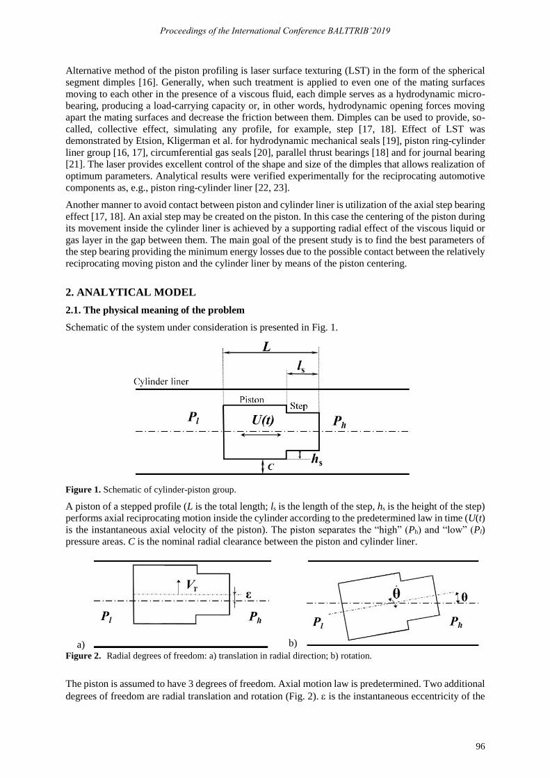
Schematic of the system under consideration is presented in Fig. 1.
Figure 1. Schematic of cylinder-piston group.
A piston of a stepped profile (L is the total length; ls is the length of the step, hs is the height of the step)
performs axial reciprocating motion inside the cylinder according to the predetermined law in time (U(t)
is the instantaneous axial velocity of the piston). The piston separates the “high” (Ph) and “low” (Pl)
pressure areas. C is the nominal radial clearance between the piston and cylinder liner.
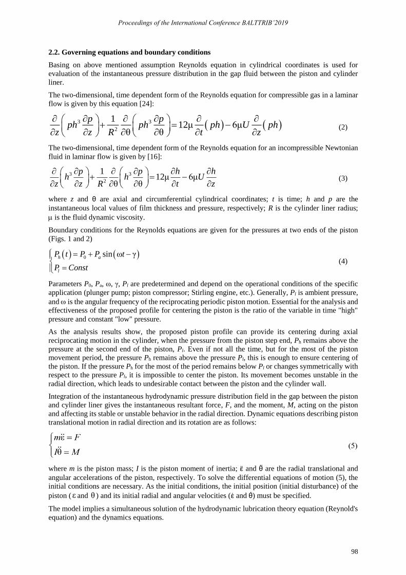
Figure 2. Radial degrees of freedom: a) translation in radial direction; b) rotation.
The piston is assumed to have 3 degrees of freedom. Axial motion law is predetermined. Two additional
degrees of freedom are radial translation and rotation (Fig. 2). is the instantaneous eccentricity of the
a) b)

Proceedings of the International Conference BALTTRIB’2019
97
piston during its radial translational motion; Vr is the instantaneous piston radial velocity; is the
instantaneous rotation angle and θ̇ is the instantaneous angular velocity.
Nondimensional parameters of the step profiles are assumed as follows:
sαl
L= sβ
C h
C
+= (1)
The instability of the piston-cylinder liner system is manifested in their uncontrolled relative radial and
rotational motion. This motion leads to their undesirable contact with cylinder liner and as a result to
friction loses, noise, wear and reduces lifetime of the parts.
There are a two main factors that explain the unstable radial motion:
1. Between two parallel and smooth surfaces, the pressure distribution does not depend on the gap
between them. That is, in the case of a parallel piston and cylinder, the hydrodynamic forces are
uniform around the piston, regardless of its eccentricity, . It means that every infinitesimal
radial disturbance can force the piston to move in the direction of the cylinder liner up to the
contact. Only the squeeze effect slightly dumps the radial motion.
2. As soon as the piston has a slight inclination (inclination), , this will lead to a converging gap
on one side and a diverging gap on the opposite side (Fig. 2b). High pressure is created in the
converging gap, while pressure is reduced in the diverging gap. This leads to a nonzero total
radial force and torque, which, in turn, increase the inclination of the piston and move it toward
the cylinder liner up to the mechanical contact.
To stabilize this system, the piston surface must be modified so that the pressure distribution is highly
dependent on the local clearance between the cylinder and the piston. In addition, a decrease in the local
gap should increase the local pressure, which, in turn, will lead to an increase in the gap in the opposite
direction. In other words, this will create the stiffness of the fluid film, which always acts to return the
cylinder to its center position. Since it is necessary to prevent both radial movement and tilt, maximum
stiffness should be created at the edges of the piston or along the whole piston.
An increase in stiffness should be achieved along with a minimal increase in undesirable fluid leakage.
2.2. Main assumptions
1. The radial clearance between the piston and cylinder liner, is much smaller than the cylinder
radius. Thus, the piston tilt is small.
2. The radial variation of the fluid density, viscosity, pressure and temperature across the narrow
gap between piston and cylinder is negligible.
3. The fluid flow is laminar and the entrance effect is neglected.
4. The working fluid may be incompressible liquid or compressible ideal gas with viscosity that is
function of the temperature only.
5. The clearance between the cylinder liner and piston is significantly larger than the molecular
path so no slip conditions on the walls is assumed.
6. The system is assumed to be isothermal.
7. The fluid inertia is neglected. There is no time dependence in the flow problem formulation.
Namely, the time response of the fluid to new boundary conditions is negligible small.
8. The piston and the cylinder liner are assumed to be non-deformable rigid bodies.
9. The axial motion of the cylinder is fully predetermined and cannot be affected by the radial
translation and rotation.
10. To reduce the number of degrees of freedom, it is assumed that the piston translates and rotates
in the same plane.
Proceedings of the International Conference BALTTRIB’2019
98
2.2. Governing equations and boundary conditions
Basing on above mentioned assumption Reynolds equation in cylindrical coordinates is used for
evaluation of the instantaneous pressure distribution in the gap fluid between the piston and cylinder
liner.
The two-dimensional, time dependent form of the Reynolds equation for compressible gas in a laminar
flow is given by this equation [24]:
( ) ( )3 3
2
112μ 6μ
θ θ
p pph ph ph U ph
z z R t z
+ = −
(2)
The two-dimensional, time dependent form of the Reynolds equation for an incompressible Newtonian
fluid in laminar flow is given by [16]:
3 3
2
112μ 6μ
θ θ
p p h hh h U
z z R t z
+ = −
(3)
where z and θ are axial and circumferential cylindrical coordinates; t is time; h and p are the
instantaneous local values of film thickness and pressure, respectively; R is the cylinder liner radius;
is the fluid dynamic viscosity.
Boundary conditions for the Reynolds equations are given for the pressures at two ends of the piston
(Figs. 1 and 2)
( ) ( )0 sin ω γh a
l
P t P P t
P Const
= + −
= (4)
Parameters P0, Pa, ω, γ, Pl are predetermined and depend on the operational conditions of the specific
application (plunger pump; piston compressor; Stirling engine, etc.). Generally, Pl is ambient pressure,
and is the angular frequency of the reciprocating periodic piston motion. Essential for the analysis and
effectiveness of the proposed profile for centering the piston is the ratio of the variable in time "high"
pressure and constant "low" pressure.
As the analysis results show, the proposed piston profile can provide its centering during axial
reciprocating motion in the cylinder, when the pressure from the piston step end, Ph remains above the
pressure at the second end of the piston, Pl. Even if not all the time, but for the most of the piston
movement period, the pressure Ph remains above the pressure Pl, this is enough to ensure centering of
the piston. If the pressure Ph for the most of the period remains below Pl or changes symmetrically with
respect to the pressure Pl, it is impossible to center the piston. Its movement becomes unstable in the
radial direction, which leads to undesirable contact between the piston and the cylinder wall.
Integration of the instantaneous hydrodynamic pressure distribution field in the gap between the piston
and cylinder liner gives the instantaneous resultant force, F, and the moment, M, acting on the piston
and affecting its stable or unstable behavior in the radial direction. Dynamic equations describing piston
translational motion in radial direction and its rotation are as follows:
where m is the piston mass; I is the piston moment of inertia; ε̈ and θ̈ are the radial translational and
angular accelerations of the piston, respectively. To solve the differential equations of motion (5), the
initial conditions are necessary. As the initial conditions, the initial position (initial disturbance) of the
piston ( ε and θ ) and its initial radial and angular velocities (ε̇ and θ)̇ must be specified.
The model implies a simultaneous solution of the hydrodynamic lubrication theory equation (Reynold's
equation) and the dynamics equations.

Proceedings of the International Conference BALTTRIB’2019
99
2.3. Numerical solution
Because of the cumbersome nature of the analytical model, the problem of simultaneous solution of
equations was solved numerically.
The solver of the Reynold’s equations, Eqs. (2) and (3), with boundary conditions, Eq. (4), (algorithm
and computer code) was developed based on the finite difference method that leads to a set of algebraic
equations for the nodal values of the pressure, which should be solved with the corresponding boundary
conditions.
Dynamics equations, Eq. (5), are also solved numerically using the Euler or fourth order Runge-Kutta
methods with given initial conditions.
At each time step, the Reynold’s equation is solved for the instantaneous axial pressure drop, the axial
piston velocity, the radial and tilt piston position, radial and tilt piston velocities. The instantaneous
Reynold’s equation solution gives the pressure map within the gap between the piston and the cylinder
liner.
Integration of the pressure distribution gives the resultant force and moment acting at the current
moment of time on the piston. Substituting these instantaneous values of the force and moment into two
dynamical equations, Eq. (5), of the piston motion, the radial and tilt piston position (and as a
consequence, the local radial gap map), radial and tilt piston velocities may be evaluated at the next time
step. These results are returned to the Reynolds equation Eqs. (2) or (3), etc.
After simulating many time steps, a picture of the longitudinal, transverse and rotational motion of the
piston inside the cylinder liner appears. Based on the obtained results, it is possible to estimate how
close the piston approaches the cylinder wall during the reciprocating motion.
3. RESULTS
3.1. Piston profile optimization criteria
Piston profile optimization criteria may be formulated as follows:
• Quick piston centering;
• Providing maximum radial translational and rotational stiffness of fluid or gas layer in the
piston-cylinder gap (Radial perturbation of the piston leads to a rapid increase in the force and
moment that return the piston to the central position);
• Providing minimum leakage throw the piston-cylinder gap. (The analysis shows that the
profiling of the piston relative to its base profile has almost no effect on the unwanted leakage)
3.2. Numerical results
The search for optimal geometry included the analysis of the following cases:
• an existing cylindrical piston;
• piston with a step profile from the high pressure area side;
• piston with a step profile from the low pressure area side;
• piston with a step profile on both sides.
In addition, the parametric analysis included the consideration of various aspect ratios, and , (see Eq.
(1)) of the step.
As already mentioned above, a numerical analysis showed that in cases where a step on the piston profile
is made from the side of the low pressure region or when the steps are made at both ends of the piston
profile, it is impossible to stabilize the movement of the piston along the cylinder axis.
Figures 3 presents the results for the cases where the time-varying pressure remains all the time above
the pressure at the other end of the piston, and the step on the piston profile is made at the end of the

Proceedings of the International Conference BALTTRIB’2019
100
high pressure region. The results in these figures are presented in the form of a minimum piston-cylinder
gap, varying in time for different parameters of the step.
a) b)
Figure 3. Minimum Piston-Cylinder Gap for a) β=1.1; b) α=0.1.
During the reciprocating motion piston surface points approach or move away from the cylinder liner.
Minimum gap corresponds to point of piston surface that approached closest to the cylinder.
Dimensionless gap is defined as the instantaneous gap normalized with respect to the gap between the
same piston point and the cylinder liner in the central position. So, this value may change between 0
(contact) and 1 (central position). The same radial parallel displacements were chosen as the initial
excitation of the pistons of the stepped profile. The final result is independent of the magnitude of this
displacement. The tilt angle was added as the initial disturbance of the non-profiled cylindrical piston.
Therefore, the initial minimum clearance between the non-profiled piston and the cylinder is different
from the stepped piston. It can be seen that non-profiled smooth cylindrical piston motion along the
cylinder axis is unstable. The step profile from the high-pressure area side stabilizes the piston motion
along the cylinder axis and prevents contact between the piston and cylinder liner.
The piston centering rate depends on the parameters of the step. In the considered parametric analysis,
the fastest centering process was achieved for the dimensionless step depth = 1.1. A step length of
10% of the piston length was sufficient to quickly center the piston.
4. CONCLUSIONS
Analysis shows that the step profile from the high-pressure area side provides the movement of the
piston along the cylinder liner axis and prevents contact between them.
Numerical analysis allows to evaluate the optimum piston profile parameters for the specific
applications, depending on the lubricant properties, kinematics (geometry) of the system and operating
conditions.
The model allows to evaluate the stiffness of the support lubricant layer due to the piston disturbance
from the central position.
The analysis shows that the profiling of the piston relative to its base profile has almost no effect on
unwanted leakage in the gap between the piston and the cylinder.
ACKNOWLEDGEMENT
The research reported here was supported in parts by Ricor, Ltd., Cryogenic & Vacuum Systems, the
Israeli National Authority for Technological Innovation and PetroChina Research Institute of Petroleum
Exploration and Development. The authors gratefully acknowledge this support.
REFERENCES
[1] Yamaguchi A. and Tanioka Y. Motion of Pistons in Piston Type Hydraulic Machines: Theoretical Analysis.
Bull, of the JSME 19, 130 (1976) 402–407.
0.0
0.2
0.4
0.6
0.8
1.0
0.0 2.0 4.0 6.0
Dim
ensi
on
less
Min
imu
m G
ap
Dimensionless Time (cycles)
=0.1
=0.2
=0.3
no step
0.0
0.2
0.4
0.6
0.8
1.0
0.0 2.0 4.0 6.0
Dim
ensi
on
less
Min
imu
m G
ap
Dimensionless Time (cycles)
=1.04
=1.1
=1.2
no step

Proceedings of the International Conference BALTTRIB’2019
101
[2] Yamaguchi A. and Tanioka Y. Motion of Pistons in Piston Type Hydraulic Machines: Experiments. Bull, of
the JSME 19, 130 (1976) 408–412.
[3] Etsion I. and Magen M. Piston Vibration in Piston-Cylinder Systems. ASME, Journal of Fluids Engineering
102, 1 (1980) 26–33.
[4] Cheng J., Zeng X., Liu Z., Yu X., Feng Q. Research on dynamic modeling and electromagnetic force centering
of piston/piston rod system for labyrinth piston compressor. Proceedings of the Institution of Mechanical
Engineers, Part I: Journal of Systems and Control Engineering 230, 8 (2016) 786–798.
[5] Xie Jing, Zeng Xiangjun, Zhang Meimei, Cheng Junming, Wang Hang, Implementation of active magnetic
control system for piston centering in labyrinth piston compressor. Mechatronics 54 (2018) 52–67. [6] Etsion, I. An Optimum Step Design for Centering Pistons. ASME Journal of Fluids Engineering 97, 4 (1975)
621–624.
[7] Etsion, I., and Hamrok, B.J. Optimum Step Design for Centering of Pistons Moving in an Incompressible Fluid,
NASA Technical Note, NASA TN D-8345, 1976, 20 p.
[8] Etsion, I., and Hamrok, B.J. Optimum Step Design for Centering of Pistons Moving in an Incompressible Fluid.
ASME Journal of Fluids Engineering 99, 4 (1977) 675–680.
[9] Gommed, K., and Etsion, I. Dynamic Analysis of Gas Lubricated Reciprocating Ringless Pistons – Basic
Modeling. ASME Journal of Tribology 115 2 (1993) 207–213.
[10] Gommed, K., and Etsion, I. Parametric Study of the Dynamic Performance of Gas Lubricated Ringless Piston.
ASME Journal of Tribology 116 1 (1994) 63–69.
[11] Etsion, I., and Gommed, K. Improved Design with Noncylindrical Profiles of Gas-Lubricated Ringless Piston.
ASME Journal of Tribology 117 1 (1995) 143–147.
[12] Prata, A. T., Fernandes, J.R.S., and Fagotti, F. Dynamic Analysis of Piston Secondary Motion for Small
Reciprocating Compressors. ASME Journal of Tribology 122 4 (2000) 752–760.
[13] Kim, T. J., and Han, J.S. Comparison of the Dynamic Behavior and Lubrication Characteristics of a
Reciprocating Compressor Crankshaft in Both Finite and Short Bearing Models. STLE Tribology Transactions 47
1 (2004) 61–69.
[14] Cho, J.R, and Moon, S.J. A numerical analysis of the interaction between the piston oil film and the component
deformation in a reciprocating compressor. Tribology International 38 5 (2005) 459–468.
[15] Kumar, S., and Bergada, J.M. The effect of piston grooves performance in an axial piston pumps via CFD
analysis. Int. Journal of Mech. Science 66 (2013) 168–179.
[16] Ronen, A., Kligerman, Y., and Etsion, I. Friction-Reducing Surface-Texturing in Reciprocating Automotive
Components. STLE Tribology Transactions 44 3 (2001) 359–366.
[17] Kligerman, Y., Etsion, I., and Shinkarenko, A. Improving Tribological Performance of Piston Rings by Partial
Surface Texturing. ASME, Journal of Tribology 127 3 (2004) 632–638.
[18] Brizmer, V., Kligerman, Y., and Etsion, I. A Laser Surface Textured Parallel Thrust Bearing. STLE Tribology
Transactions 46 3 (2003) 397–403.
[19] Etsion, I., Kligerman, Y., and Halperin, G. Analytical and Experimental Investigation of Laser-Textured
Mechanical Seal Faces. STLE Tribology Transactions 42 3 (1999) 511–516.
[20] Kligerman, Y. and Etsion, I. Analysis of the Hydrodynamic Effects in a Surface Textured Circumferential
Gas Seal. STLE Tribology Transactions 44 3 (2001) 472–478.
[21] Brizmer, V. and Kligerman, Y. A Laser Surface Textured Journal Bearing. ASME, Journal of Tribology 134
3 (2012) 031702(1–9).
[22] Ryk, G., Kligerman, Y., and Etsion, I. Experimental Investigation of Laser Surface Texturing for
Reciprocating Automotive Components. STLE Tribology Transactions 45 4 (2002) 444–449.
[23] Ryk, G., Kligerman, Y., Etsion, I., and Shinkarenko, A. Experimental Investigation of Partial Laser Surface
Texturing for Piston Rings Friction Reduction. STLE Tribology Transactions 48 4 (2005) 583–588.
[24] Szeri A. Z. Fluid Film Lubrication: Theory and Design, Cambridge University Press, 2005, 428 p.