Cementitious materials in OPERA disposal concept ... - · PDF fileOPERA-PG-COV020 Page 1 of 17...
24
Cementitious materials in OPERA disposal concept in Boom Clay OPERA-PG-COV020
Transcript of Cementitious materials in OPERA disposal concept ... - · PDF fileOPERA-PG-COV020 Page 1 of 17...
Cementitious materials in OPERA disposal concept in Boom Clay
OPERA-PG-COV020

OPERA-PG-COV020 Title Cementitious materials in OPERA disposal concept in Boom Clay Authors: E.V. Verhoef, A.M.G. de Bruin, R.B. Wiegers, E.A.C. Neeft, G. Deissmann Date of publication 30 April 2014 Keywords: concrete, mortar, function, requirement COVRA N.V.

Summary ..................................................................................................1 1. Introduction .........................................................................................2
1.1. Background ....................................................................................2 1.2. Objectives ......................................................................................2 1.3. Realization .....................................................................................3 1.4. Explanation contents .........................................................................3
2. Functions of cementitious materials ............................................................4 3. Mechanical support ................................................................................6
3.1. Requirements ..................................................................................6 3.1.1. Sulphate resistance .....................................................................6
3.2. Suggested composition .......................................................................7 3.3. Evidence and arguments .....................................................................7 3.4. Available knowledge on other compositions ..............................................7
4. Enclosure emplaced waste ........................................................................8 4.1. Requirements fluid properties ..............................................................8
4.1.1. Density ....................................................................................8 4.1.2. Fluidity ....................................................................................8
4.2. Requirements stiffening .....................................................................8 4.3. Requirements hardened properties ........................................................9
4.3.1. Strength ...................................................................................9 4.3.2. Retrievability .............................................................................9 4.3.3. Thermal conductivity ...................................................................9 4.3.4. Permeability ..............................................................................9
4.4. Suggested composition ..................................................................... 10 4.5. Evidence and arguments ................................................................... 10 4.6. Available knowledge on other compositions ............................................ 11
5. Containment of waste ........................................................................... 12 5.1. HLW ........................................................................................... 12
5.1.1. Requirements .......................................................................... 12 5.1.2. Suggested composition................................................................ 12 5.1.3. Evidence and arguments .............................................................. 13 5.1.4. Other compositions .................................................................... 13
5.2. LILW – Processed at COVRA ................................................................ 13 5.2.1. Requirements .......................................................................... 13 5.2.2. Composition ............................................................................ 13 5.2.3. Evidence and arguments .............................................................. 14
5.3. LILW – to be processed ..................................................................... 14 6. References ........................................................................................ 16 Appendix 1 – (Im)permeability .........................................................................1

OPERA-PG-COV020 Page 1 of 17
Summary The disposal concept for OPERA in clay published in 2011 contains many cementitious materials. A description of compositions of these materials was required in order to have a mutual set that can be used in the different research groups working within OPERA. In this report, this description includes the definition of the function of the cementitious material in the disposal facility, the requirements to fulfil this function and the available knowledge to potentially fulfil the requirements (evidence and arguments) of the suggested composition. Three functions have been defined: mechanical support, enclosure of emplaced waste and containment of waste. The mechanical support is provided by the gallery lining during the constructional and operational phase of a geological disposal facility. Concrete segments made with Portland fly ash cement are proposed. Enclosure of emplaced waste is provided by the backfill. Foam concrete made with Portland cement is proposed. Containment of waste is provided by the waste package. Concrete made with Portland cement is proposed for the containment of High Level Waste and depleted uranium. For processed Low and Intermediate Level Waste, concrete made with blast furnace slag cement is proposed; it is the concrete made by COVRA. The proposed aggregates can be limestone, depleted uranium or quartz. In line with the published disposal concept, a separate section for disposal of depleted uranium is assumed; the use of depleted uranium as aggregates for the fabrication of the supercontainer is not considered. The water-cement ratios for all the proposed cementitious materials range from 0.39 to 0.50.

OPERA-PG-COV020 Page 2 of 17
1. Introduction
1.1. Background
Radioactive substances and ionizing radiation are used and generated in medicine, industry, agriculture, research, education and electricity production. As a consequence, these activities generate radioactive waste. Current policy in the Netherlands is that radioactive waste is collected, treated and stored by COVRA (Centrale Organisatie Voor Radioactief Afval). After interim storage for a period of at least 100 years, radioactive waste is intended for disposal. There is a world-wide scientific and technical consensus that geological repositories represent a safe disposal option for radioactive waste. Geological disposal is emplacement of radioactive waste in deep underground formations. The goal of geological disposal is isolation of radioactive waste from our living environment in order to avoid exposure of future generations to ionising radiation from the waste. OPERA (OnderzoeksProgramma Eindberging Radioactief Afval) is the third Dutch research programme on geological disposal of radioactive waste and started in 2011. In 2011, the outlines of a disposal concept in clay has been published [Verhoef, 2011a]. For different purposes, cementitious materials are used in this concept.
1.2. Objectives
In this report, the compositions of the cementitious materials are defined for the OPERA disposal concept in clay [Verhoef, 2011a] in order to have a mutual set of cementitious compositions to be used for different research groups working in OPERA. The cementitious materials applied during construction and operation are the same cementitious materials meant for the post closure period. Hence, there is a build-up of requirements which makes the selections of the cementitious materials (in terms of composition) for the respective functions rather complex. Moreover, the choice of the composition for a given application is based on a multitude of aspects ranging from constructive demands (based on both static and dynamic forces), available processing techniques, safety & health (such as fire protection), maintenance constraints and last (and often by no means the least) both the absolute costs (budget constraints) and relative costs (intercomparison with other available options). For such a complex task a team of specialists will work together for several years to translate the demands into technical specifications and subsequent developing in an iterative process the most optimal solution and therewith also the choice of compositions of the cementitious materials. The translation of all relevant matters into a list of specifications and demands is not yet available. As a consequence, within the relative limited setting of the OPERA, it is not possible to look into all relevant matters and their interactions. What has been done is a description of an approach how certain potentially interesting choices for the composition of cementitious materials for the various functions have been derived. It will be clear that these choices will fulfil some of the major requirements without claiming that they fulfil all relevant requirements at the same time nor that they are being (economical) optimal choices. In this report, there is a preference to quantify requirements and for choosing compositions with proven properties. It is important to note that the functions and choices of the compositions are based on the principle of current best available techniques and may iteratively develop over a period of at least 100 years. This report can be used to start the definitions of the compositions. Associated effects during post-closure of the disposal facility e.g. interactions with other repository components are investigated in OPERA. These investigations may result in a substantiated change of the chosen compositions made in this report. Concrete used for surface facilities are excluded in this report.

OPERA-PG-COV020 Page 3 of 17
1.3. Realization
IBR initiated the discussion to use the same type of cementitious materials between the different research groups in OPERA. The framework to support the decision for the choice of cementitious material was developed by COVRA and IBR. This document is based on the discussions of the elaboration of the description of the choices for the compositions
between IBR, BS, SCKCEN, NRG and COVRA.
1.4. Explanation contents
This is a ‘stand alone’ document describing the relevant present available knowledge for cementitious materials to be used in a geological disposal facility in Boom Clay in the Netherlands; the use of references is limited to provide the possibility to check the refereed information. Following IAEA recommendations [IAEA, 2012:p.99] the document has been set up to enable the traceability of assumptions by e.g. referring to primary references. The sources from which information has been compiled can be lengthy. Therefore, the page(s) in the sources where the described assumption or parameter value can be found are specified in order to facilitate traceability of the referred information. Chapter 2 contains the considered functions of the cementitious materials used in the underground facility for the geological disposal of radioactive waste, the justification of the simplifications made for OPERA and the requirements relevant for all cementitious materials. For each function, one chapter is used for the description of the additional simplifications and requirements, proposed composition and available knowledge of the composition and alternatives. For clarity, Chapter 3, 4 and 5 have - if appropriate - the same headings. Standard practices in other fields are indicated in order to stimulate the information exchange from these fields. The references are shown in Chapter 6.
OPERA-PG-COV020 Page 4 of 17
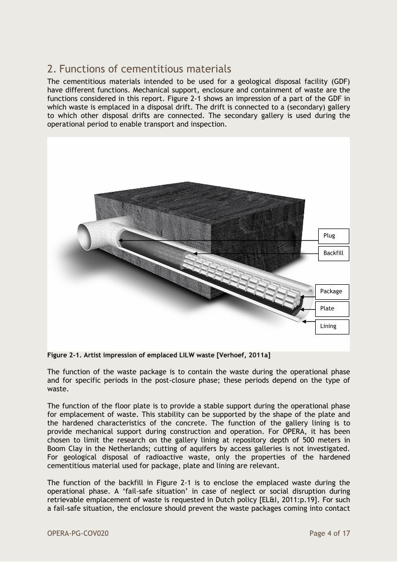
2. Functions of cementitious materials The cementitious materials intended to be used for a geological disposal facility (GDF) have different functions. Mechanical support, enclosure and containment of waste are the functions considered in this report. Figure 2-1 shows an impression of a part of the GDF in which waste is emplaced in a disposal drift. The drift is connected to a (secondary) gallery to which other disposal drifts are connected. The secondary gallery is used during the operational period to enable transport and inspection.
Figure 2-1. Artist impression of emplaced LILW waste [Verhoef, 2011a]
The function of the waste package is to contain the waste during the operational phase and for specific periods in the post-closure phase; these periods depend on the type of waste. The function of the floor plate is to provide a stable support during the operational phase for emplacement of waste. This stability can be supported by the shape of the plate and the hardened characteristics of the concrete. The function of the gallery lining is to provide mechanical support during construction and operation. For OPERA, it has been chosen to limit the research on the gallery lining at repository depth of 500 meters in Boom Clay in the Netherlands; cutting of aquifers by access galleries is not investigated. For geological disposal of radioactive waste, only the properties of the hardened cementitious material used for package, plate and lining are relevant. The function of the backfill in Figure 2-1 is to enclose the emplaced waste during the operational phase. A ‘fail-safe situation’ in case of neglect or social disruption during retrievable emplacement of waste is requested in Dutch policy [EL&I, 2011:p.19]. For such a fail-safe situation, the enclosure should prevent the waste packages coming into contact
Backfill
Package
Plate
Lining
Plug

OPERA-PG-COV020 Page 5 of 17
with water in the unlikely case of flooding of the facility. As a consequence, the hardening time, the fluid properties and hardened properties of the cementitious material of the enclosure are relevant. The function of the plug is to hydraulically seal off the disposal drift. This plug is presumed to be made of clay (e.g. bentonite [Bock, 2008:p.255]). In the OPERA disposal concept, the possibility to retrieve the waste is included in the operational phase. In this concept, the disposal drifts with emplaced waste are enclosed from the other galleries. These secondary and access galleries are not backfilled in order to facilitate the retrievability of waste [Verhoef, 2011a:p.6]. At closure of the repository, parts of the mechanical support at the access galleries may be removed and these galleries will be backfilled since the repository itself will then no longer need maintenance and other supporting activities. This backfill does not need to be the same material as used for the disposal drifts with emplaced waste. During the post-closure phase it would still be possible to retrieve the waste but would require drilling operations and reconstruction of the facility [Verhoef, 2011a:p.7]. In Dutch policy, retrieval of waste, if deemed necessary for whatever reason, should be possible for decades up to more than a century after closing the repository [EL&I, 2011:p.19]. In OPERA, a facility in which only the drifts with emplaced waste are backfilled is presumed to be present for up to a century. The period in time for which the cementitious materials should fulfil their function is expected to be at least 100 years. Ingress of agents by which these materials can be degraded till such an extent that they no longer can fulfil their function is expected. Not fulfil of functions without ingress of agents e.g. internal reaction can be prevented by appropriate choice of aggregates and cement. There are some requirements for the chemical composition of all cementitious materials. Those materials with a pH smaller than 11 (low pH cement) are not considered in this disposal concept and therefore - for simplicity - amorphous or reactive silica is excluded to be chosen as aggregates in order prevent alkali silica reactions. There will be metal used in the repository and the cementitious materials should therefore be low in chloride content (e.g. <0.2 Cl- wt% for cement and <0.02 wt% Cl- for aggregates [Betonpocket, 2009:p.110, 213]) in order to limit corrosive species. Admixtures such as plasticisers and foaming agents may be inevitable and admixtures that do not form migration-enhancing species with radionuclides nor be corrosive to metals are available. For the enclosure of emplaced waste by backfill as well as the containment of heat-generating HLW waste, the cementious materials should be low in SO3 content (e.g. <0.2 wt% for aggregates [Betonpocket, 2009:p.213]) in order to limit delayed ettringite formation. The suggested cements in the cementitious materials are classified according to NEN-EN 197-1.

OPERA-PG-COV020 Page 6 of 17
3. Mechanical support The mechanical support against clay convergence is expected to be made during construction of the facility using the wedge block technique and tunnel boring machines. The potential mechanical support should be larger than the host rock pressure at a depth of 500 meter in Boom Clay; about 10 MPa. The hardened properties e.g. compressive strength of the concrete and thickness of the lining determine both whether sufficient support can be achieved. In practice mortar is used to accommodate gaps and damage made during construction but for OPERA only concrete segments are considered. Mechanical support by the gallery lining, drifts and floor plate is expected to be needed at least for the construction and operational phase of the facility. The considered period for emplacement of waste is 40 years [Verhoef, 2011a:p.6]. A century to have facilitated retrieval of waste is assumed therefore mechanical support should be provided for about 150 years. For the post-closure phase, a limit of the use of metal such as steel is preferred in order to limit the potential formation of hydrogen gas [Berckmans, 2013:p.215]. Unreinforced concrete segments are therefore considered [Verhoef, 2011a:p.4]. In the applications as foreseen as mechanical support, basically, the concrete must be capable to resist also bending forces up to a certain extent. These bending forces will be both static (pressure of the surrounding rock) as well as dynamic (due to all kinds of activities such as transport). The changing load in the galleries due to the disposal of the waste packages is a form of semi static change of the load which will incur different mechanical settings over a longer period of time. For reasons that concrete has generally rather poor bending/tensile properties traditionally reinforcement is used in load bearing applications. For geological disposal facilities, the changes in dynamic force are expected to be smaller as the transport of heavy loads is limited to the emplacement of waste especially when air-cushions are used [Bel, 2005]. At the intersections e.g. between the disposal galleries and access gallery, reinforcement may be necessary [Bastiaens, 2003:p.12]. As a start, similarly as the underground research laboratory HADES in Belgium, unreinforced concrete [Bastiaens, 2003:p.11] as a lining is used in OPERA.
3.1. Requirements
3.1.1. Sulphate resistance
The permeability in concrete segments is usually sufficiently small to consider it impermeable for the construction and operational phase; leakage usually occurs at the joints of the concrete segments. In the previous research programme CORA, the considered Boom Clay at this depth was expected to be a marine deposit due to its age and at a depth of more than 400 meter no locations have been found in the Netherlands with fresh water of such aged deposits in the previous research programme [Rijkers, 1998:p.59]. Apart from the requirements just described for all cementitious materials in Chapter 2, the formulated additional requirement for mechanical support would be a description for the sulphate resistance. It is required to have no degradation of the lining by ingress of sulphates with a concentration comparable to seawater for a period of at least 150 years. The content of sulphate in sea water is about 3000 mg SO4
2- mg/l [Butcher, 1992:p.194]. An additional sulphate source is the oxidation of pyrite in Boom Clay during construction of the repository. The oxidation periods are limited by the period in time to emplace the concrete segments and removal of entrapped air in excavation-induced fractures. Up to 2700 mg SO4
2- mg/l is measured at the underground research laboratory at Mol in Belgium [Geet, 2006:p.13]. Till 6000 mg SO4
2- mg/l is therefore taken into account.
OPERA-PG-COV020 Page 7 of 17
3.2. Suggested composition
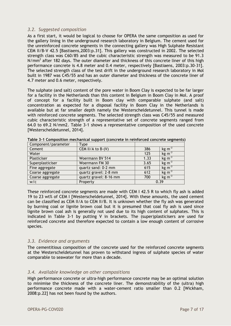
As a first start, it would be logical to choose for OPERA the same composition as used for the gallery lining in the underground research laboratory in Belgium. The cement used for the unreinforced concrete segments in the connecting gallery was High Sulphate Resistant CEM II/B-V 42.5 [Bastiaens,2003:p.31]. This gallery was constructed in 2002. The selected strength class was C60/85 and the cubic characteristic strength was measured to be 91.3 N/mm2 after 182 days. The outer diameter and thickness of this concrete liner of this high performance concrete is 4.8 meter and 0.4 meter, respectively [Bastiaens, 2003:p.30-31]. The selected strength class of the test drift in the underground research laboratory in Mol built in 1987 was C45/55 and has an outer diameter and thickness of the concrete liner of 4.7 meter and 0.6 meter, respectively. The sulphate (and salt) content of the pore water in Boom Clay is expected to be far larger for a facility in the Netherlands than this content in Belgium in Boom Clay in Mol. A proof of concept for a facility built in Boom clay with comparable sulphate (and salt) concentration as expected for a disposal facility in Boom Clay in the Netherlands is available but at far smaller depth namely the Westerscheldetunnel. This tunnel is made with reinforced concrete segments. The selected strength class was C45/55 and measured cubic characteristic strength of a representative set of concrete segments ranged from 64.0 to 69.2 N/mm2. Table 3-1 shows a representative composition of the used concrete [Westerscheldetunnel, 2014]. Table 3-1 Composition mechanical support (concrete in reinforced concrete segments)
Component/parameter Type
Cement CEM II/A to B-(V) 386 kg m-3
Water 125 kg m-3
Plasticiser Woermann BV 514 1.33 kg m-3
Superplasticiser Woermann FM 30 3.65 kg m-3
Fine aggregate quartz sand: 0-2 mm 615 kg m-3
Coarse aggregate quartz gravel: 2-8 mm 612 kg m-3
Coarse aggregate quartz gravel: 8-16 mm 700 kg m-3
w/c Property 0.39
These reinforced concrete segments are made with CEM I 42.5 R to which fly ash is added 19 to 23 wt% of CEM I [Westerscheldetunnel, 2014]. With these amounts, the used cement can be classified as CEM II/A to CEM II/B. It is unknown whether the fly ash was generated by burning coal or lignite brown coal but it is presumed that coal fly ash is used since lignite brown coal ash is generally not used due to its high content of sulphates. This is indicated in Table 3-1 by putting V in brackets. The (super)plasticisers are used for reinforced concrete and therefore expected to contain a low enough content of corrosive species.
3.3. Evidence and arguments
The cementitious composition of the concrete used for the reinforced concrete segments at the Westerscheldetunnel has proven to withstand ingress of sulphate species of water comparable to seawater for more than a decade.
3.4. Available knowledge on other compositions
High performance concrete or ultra-high performance concrete may be an optimal solution to minimise the thickness of the concrete liner. The demonstrability of the (ultra) high performance concrete made with a water-cement ratio smaller than 0.2 [Wickham, 2008:p.22] has not been found by the authors.
OPERA-PG-COV020 Page 8 of 17
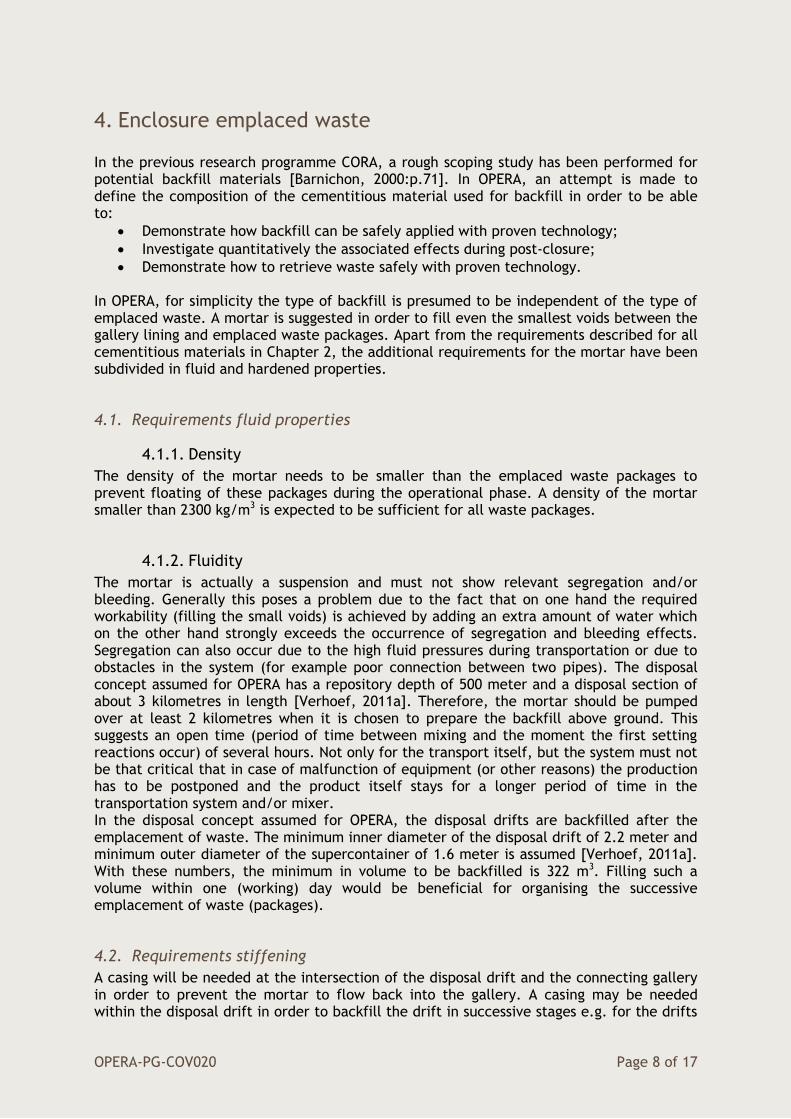
4. Enclosure emplaced waste In the previous research programme CORA, a rough scoping study has been performed for potential backfill materials [Barnichon, 2000:p.71]. In OPERA, an attempt is made to define the composition of the cementitious material used for backfill in order to be able to:
Demonstrate how backfill can be safely applied with proven technology;
Investigate quantitatively the associated effects during post-closure;
Demonstrate how to retrieve waste safely with proven technology. In OPERA, for simplicity the type of backfill is presumed to be independent of the type of emplaced waste. A mortar is suggested in order to fill even the smallest voids between the gallery lining and emplaced waste packages. Apart from the requirements described for all cementitious materials in Chapter 2, the additional requirements for the mortar have been subdivided in fluid and hardened properties.
4.1. Requirements fluid properties
4.1.1. Density
The density of the mortar needs to be smaller than the emplaced waste packages to prevent floating of these packages during the operational phase. A density of the mortar smaller than 2300 kg/m3 is expected to be sufficient for all waste packages.
4.1.2. Fluidity
The mortar is actually a suspension and must not show relevant segregation and/or bleeding. Generally this poses a problem due to the fact that on one hand the required workability (filling the small voids) is achieved by adding an extra amount of water which on the other hand strongly exceeds the occurrence of segregation and bleeding effects. Segregation can also occur due to the high fluid pressures during transportation or due to obstacles in the system (for example poor connection between two pipes). The disposal concept assumed for OPERA has a repository depth of 500 meter and a disposal section of about 3 kilometres in length [Verhoef, 2011a]. Therefore, the mortar should be pumped over at least 2 kilometres when it is chosen to prepare the backfill above ground. This suggests an open time (period of time between mixing and the moment the first setting reactions occur) of several hours. Not only for the transport itself, but the system must not be that critical that in case of malfunction of equipment (or other reasons) the production has to be postponed and the product itself stays for a longer period of time in the transportation system and/or mixer. In the disposal concept assumed for OPERA, the disposal drifts are backfilled after the emplacement of waste. The minimum inner diameter of the disposal drift of 2.2 meter and minimum outer diameter of the supercontainer of 1.6 meter is assumed [Verhoef, 2011a]. With these numbers, the minimum in volume to be backfilled is 322 m3. Filling such a volume within one (working) day would be beneficial for organising the successive emplacement of waste (packages).
4.2. Requirements stiffening
A casing will be needed at the intersection of the disposal drift and the connecting gallery in order to prevent the mortar to flow back into the gallery. A casing may be needed within the disposal drift in order to backfill the drift in successive stages e.g. for the drifts

OPERA-PG-COV020 Page 9 of 17
with a length of 200 meter. For convenient operational procedures, it would be beneficial that the strength development is such that the casing can be removed within similar periods as used today e.g. 3 days. Shrinkage should be limited as well as bleeding or segregation as long as the mortar is not set.
4.3. Requirements hardened properties
Hardening continues after setting of the mortar. A hardening time of 28 days is envisaged for defining the characteristics of the properties of the hardened mortar similarly as frequently used for characterisation of hardened concrete.
4.3.1. Strength
The backfill should prevent cave-in of the supercontainer when - in the post-closure phase – the concrete segments in the lining no longer provide sufficient mechanical support. The lithostatic pressure at 500 meter depth is 10 MPa. The minimum value of the compressive strength of the backfill is therefore set 10 N/mm2.
4.3.2. Retrievability
The backfill has to be removed in order to allow retrieval of the waste (package). The methodology to remove the backfill should limit accompanied damage to the waste package in order to envisage safe transport of the waste. A high pH of the backfill is beneficial for the durability of the steel envelope of the supercontainer and steel containers containing LILW.
4.3.3. Thermal conductivity
A thermal conductivity constraint on the backfill is limited to heat generating waste: the temperature of the Supercontainer should not exceed 100 degrees Celsius after emplacement of this waste package [Weetjes, 2009:p.7]. There is literature that suggest to put a constraint on the minimum density of the backfill in order to prevent the backfill to act as a thermal insulator and indicate that a minimum value in thermal conductivity of 1 Wm-1K-1 is sufficient [Humbeeck, 2007:p.342] or should match the thermal properties of clay [Verhoef, 2011a, p.12]. On the other hand, calculations without backfill in which there is a gap of air between the emplaced waste (package) and gallery lining shows little difference as long as the distance between the outside of waste package (Supercontainer) and gallery lining is less than 25 centimetre [Wickham, 2008: p.61]. It is uncertain which minimum value in thermal conductivity of the backfill should be taken into account to achieve this 100 degrees objective for the Dutch case with an interim storage period of at least 100 years in which the maximum in heat production per canister (vitrified waste) is expected to be 200 W.
4.3.4. Permeability
As a start, it has been chosen to adapt the requirements at storage for the unlikely case of flooding of the geological disposal facility in the operational phase. At storage, the concrete made at COVRA to contain the LILW waste should prevent leaching of radionuclides from the waste package when the waste packages are flooded by seawater for one year. The adaption for disposal could be that there should be no degradation of the waste packages when exposed to seawater for one year in order to have confidence that the flooding has no impact on the post-closure evolution of the waste packages. The backfill should - in engineering terms - be impermeable.

OPERA-PG-COV020 Page 10 of 17
4.4. Suggested composition
Foamed concrete consist of cement, water, foam and (fine) aggregates. Normally, first the density(limit) is chosen based on the demands of given project. The density of foam concrete is smaller than 2300 kg/m3. Depending on the specific constrains, also a required strength is chosen. Based on this the amount of water, foam and in some cases, aggregates are calculated. Following recipe is an example of the mixture design for a foam concrete with a minimum in compressive strength of 10 MPa (28 days) and is advised by Aercrete SE, a foam concrete equipment supplier. The dry density is from 1200 until 1600 kg/m3 (the wet ones 1273 kg/m3 and 1675 kg/m3). Table 4-1 Composition enclosure emplaced waste (backfill – foam concrete)
Component
Receipt for 1 m3 of Aercrete FC 1200 to 1600
kg m-3
Type for OPERA 1200 kg m-3
1600 kg m-3
Cement 360 to 400 kg CEM I 360 400 kg m-3
Water 140 to 160 kg - 140 160 kg m-3
Fine aggregate 750 to 1100 kg Quartz sand: 0-4 mm 750 1100 kg m-3
Foaming agent Synthetic surfactant
0.57 to 0.36 l Foaming agent TM 80/23 Synthetic
1 1 kg m-3
Water 21.3 to 13.6 l Water 21.3 13.6 kg m-3
Air 434 to 277 l Air 0 0 kg m-3
w/c property 0.45 0.43
The suggested cement content is slightly larger than the foam concretes tested for the guideline CUR 181. For OPERA, the foaming agents as prescribed by Tillman Construction Chemicals are used as the density of the foaming agent from Aercrete FC is unknown. The maximum in chloride content is 0.1 wt% according to the technical specifications. The foaming agents can be combined with CEM I or CEM III but not with fly ash. The foaming agent TM 80/23 may be similar as the foaming agent Aercell A-7 developed by Aercrete as they both are of synthetic nature. In contrast to these synthetic foaming agents, foaming agents based on proteins are organic and are extracted as a by-product in the meat processing industry; these animal proteins have a greater tendency for build-up of molds. There is a preference for CEM I (Portland cement) over CEM-III because a larger lifetime of the steel envelopes is expected with the use of CEM-I.
4.5. Evidence and arguments
Foam concrete is a material which in the Netherlands was developed in the seventies of the last century and reached full commercial application during the eighties. Several mortar producing companies developed their own system of producing the foam concrete. One of the most used methodologies is on site production. On site, an installation consisting of a mortar pump and a foam generator is installed. From the (local) mortar supplier a mixture of basis material (cement, water and aggregates) is fed into the mortar pump. At the same time, foam is injected in the mixer and thus a foam containing very stable and fluid mortar is created. Although foam concrete is considered to be a specialty, over the last few decades foam concrete is used in a wide spread of (proven) applications. Amongst which are both high volume applications (in road construction, refill of large (sub)surface voids such as old harbours, filling sewage drainage systems over long distances etc.) up to small volume applications (filling of subsurface oil tanks, levelling of floors in dwellings etc.). Foam concrete has become a reliable product which can be adjusted up to a comparably high extend to the customer demands. The reliability is amongst others

OPERA-PG-COV020 Page 11 of 17
based upon the agreed specifications between constructors and customers in working with foam concrete and expected properties of foam concrete as a certified product. Such specifications are published in the Netherlands as CUR Aanbevelingen. In CUR 181, amongst others the cubic compressive strength, thermal conductivity, shrinkage and permeability-properties are published as a function of the density of the foam concrete. Thermal conductivities until 0.80 W m-1 K-1 are available. For the purpose of OPERA with a minimum density of 1200 kg m-3 a minimum value in thermal conductivity of 0.30 W m-1 K-1 can be assumed. The permeability property is expressed as 5 kg of water that has penetrated 1 square meter in 10 years. The permeability becomes 1.6×10⁻¹¹ m s-1 with these values. This value is about ten times larger than the first guess of the permeability value of the concrete made by COVRA. After backfilling, a seal made of e.g. bentonite should therefore be applied after stiffening in order to have sufficient confidence that a flooding has negligible impact on the post-closure evolution of the waste packages. The production rate is more or less depending on the capacity of the used pump but production capacities ranging from a few m3 per hour up to 100 m3/h and more are state of the art. The minimum in time for backfilling a volume of 322 m3 in the disposal drift would be slightly larger than 3 hours with this rate. Experienced stiffening time is one day implying that removal of the mortar casing is possible after one day. Shrinkage in practice has been found to be 1 ‰ for the densities relevant for OPERA. The hardened mortar itself can be removed by hand tools e.g. it can be sawn by hand. The required small forces to remove foam concrete may limit the extent in damage to the waste package in case of removal for retrieval.
4.6. Available knowledge on other compositions
The function of grout used for PRACLAY (an experiment held at the underground research laboratory in Belgium) was to create a stiff concrete mass that will not damage due to ground settlements in the future [Bakker,2009:p.34]. In a full scale test to backfill a disposal drift with an inner diameter of 3 meter with simulated emplaced waste with a diameter of 2 meter, some bleeding occurred and minor segregation. A layer of water with a thickness between 0.5 and 5 centimetre was segregated at the top of the filling. The quality of the upper layers may therefore be different from the lower layers e.g. reduced product qualities in terms of strength properties. Bleeding of the water continues until the cement paste has stiffened enough. Water-cement ratios of the grout varied between 1.34 and 1.45. Grout has stiffened within 4 days [Humbeeck, 2007: p.344]. The tested injection rate was 3 m3 per hour [Humbeeck, 2008: p.4-8]. The minimum in time for backfilling a disposal drift with emplaced waste packages and a length of 45 meter in the disposal concept in OPERA would be at least 100 hours with this rate. The removal of grout was suggested by a high-pressure beam technology for which a maximum in compressive strength of 10 MPa is assumed [Humbeeck, 2007: p.343].
OPERA-PG-COV020 Page 12 of 17
5. Containment of waste Waste packages have the objective to contain the waste. The minimum containment period after closure of the repository depends on the type of waste. Following the Belgian approach, for heat-generating High Level Waste, the package should be able to prevent the waste coming into contact with (pore)water until the decay of radionuclides no longer increases the temperature of the host rock [Smith, 2009:p.30]. The necessary period for decay is expected to be less than 1000 years [Verhoef, 2011b: p.11].
The construction of the geological disposal facility will induce some (excavation) perturbations in the host rock. After closure of the facility it is expected that these perturbations have diminished till such an extent that properties like hydraulic conductivity have the same value as the virgin host rock. For non-heat generating waste e.g. Low and Intermediate waste, the package should be able to prevent (pore)water reaching the waste until properties of the virgin rock have been achieved. This period is expected to be less than 100 years [Verhoef, 2011b: p.11]. Apart from the requirements described for all cementitious materials in Chapter 2, there are some additional requirements for the containment of each type of waste.
5.1. HLW
5.1.1. Requirements
The containment should provide a passive environment for the steel overpack surrounding the canister. The canister is the primary waste container for processed waste and is used for storage of the waste at COVRA. A low permeability to limit leaching is preferred in order to have sufficient confidence that this passive environment can last at least 1000 years.
5.1.2. Suggested composition
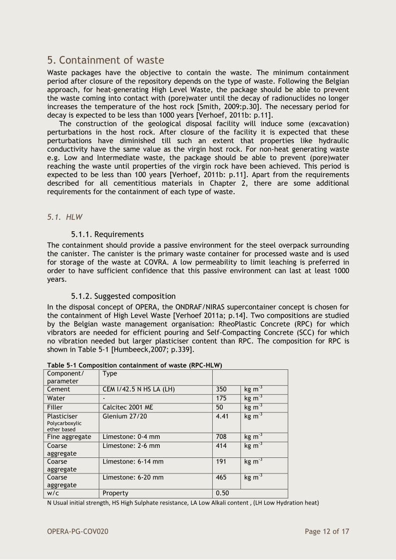
In the disposal concept of OPERA, the ONDRAF/NIRAS supercontainer concept is chosen for the containment of High Level Waste [Verhoef 2011a; p.14]. Two compositions are studied by the Belgian waste management organisation: RheoPlastic Concrete (RPC) for which vibrators are needed for efficient pouring and Self-Compacting Concrete (SCC) for which no vibration needed but larger plasticiser content than RPC. The composition for RPC is shown in Table 5-1 [Humbeeck,2007; p.339]. Table 5-1 Composition containment of waste (RPC-HLW)
Component/ parameter
Type
Cement CEM I/42.5 N HS LA (LH) 350 kg m-3
Water - 175 kg m-3
Filler Calcitec 2001 ME 50 kg m-3
Plasticiser Polycarboxylic ether based
Glenium 27/20 4.41 kg m-3
Fine aggregate Limestone: 0-4 mm 708 kg m-3
Coarse aggregate
Limestone: 2-6 mm 414 kg m-3
Coarse aggregate
Limestone: 6-14 mm 191 kg m-3
Coarse aggregate
Limestone: 6-20 mm 465 kg m-3
w/c Property 0.50
N Usual initial strength, HS High Sulphate resistance, LA Low Alkali content , (LH Low Hydration heat)

OPERA-PG-COV020 Page 13 of 17
RPC has been chosen since an important amount of dispersion in the Poisson’s ratio was found for SCC [Humbeeck,2007;p.340]. Limestone is used as aggregates in order to eliminate alkali-silica reactions.
5.1.3. Evidence and arguments
After hardening of 28 days, the mean compressive strength was measured to be 47 N/mm2, the tensile strength 3.3 N/mm2, a Poisson’s ratio of 0.16, density of 2440 kg/m3, a permeability of water of 2.1 cm3 according to NBN B 15-222. A shrinkage of 380 µm/m (0.38 ‰) was measured after 6 months [Humbeeck, 2007:p.340]. Cave-in of the supercontainer is not expected at 500 meter depth with the measured compressive strength. The permeability property has to be converted into a permeability value in order to be used for geological disposal. In practice, the construction of the supercontainer with the heat-generating waste and use of filler will be needed [Humbeeck, 2007:p.341] but for OPERA as a start, only the buffer of the supercontainer is considered as the containment of HLW.
5.1.4. Other compositions
Self-compacting concrete investigated by ONDRAF/NIRAS [Humbeeck, 2007:p.339] would be the other proposed composition.
5.2. LILW – Processed at COVRA
5.2.1. Requirements
Only solids are stored at COVRA and all waste processing at COVRA is devoted to make a stable (non-burnable) solid product e.g. bitumen is not used for processing. The requirements for the containment of LILW are based on storage conditions. The requirement at storage is a strength class C35/45. At storage, the external event of flooding by seawater is taken into account for the chosen composition of the concrete. Exposure class XS3 and XA2 in Eurocode 2 are chosen. A maximum water-cement ratio of 0.45 and a minimum cement content of 320 kg m-3 are required according to NEN 8005. The concrete has to be impermeable in engineering terms in order to prevent leaching of radionuclides during flooding.
5.2.2. Composition
Table 5-2 shows the compositions of the concrete made at COVRA. Table 5-2 Composition containment of waste (LILW processed at COVRA)
Component/ Parameter
Type
Cement CEM III/B 42.5 LH HS 407-430 kg m-3
Water - 175-185 kg m-3
Plasticiser TM OFT-II B84/39 CON. 35% (BT-SPL)
3-5 kg m-3
Fine aggregate Quartz sand : 0-4 mm 819-972 kg m-3
Coarse aggregate
Quartz gravel : 2-8 mm 891-763 kg m-3
w/c Property 0.43
LH Low Hydration heat; HS High Sulphate resistance
OPERA-PG-COV020 Page 14 of 17
The plasticiser is also suitable for the fabrication of reinforced concrete and therefore expected to contain a low enough content of corrosive species; the maximum in chloride content is 0.1 w% according to the technical specifications. The limit in size of 8 mm for the coarse aggregate is to fill the small gaps between the compressed waste containers and storage container.
5.2.3. Evidence and arguments
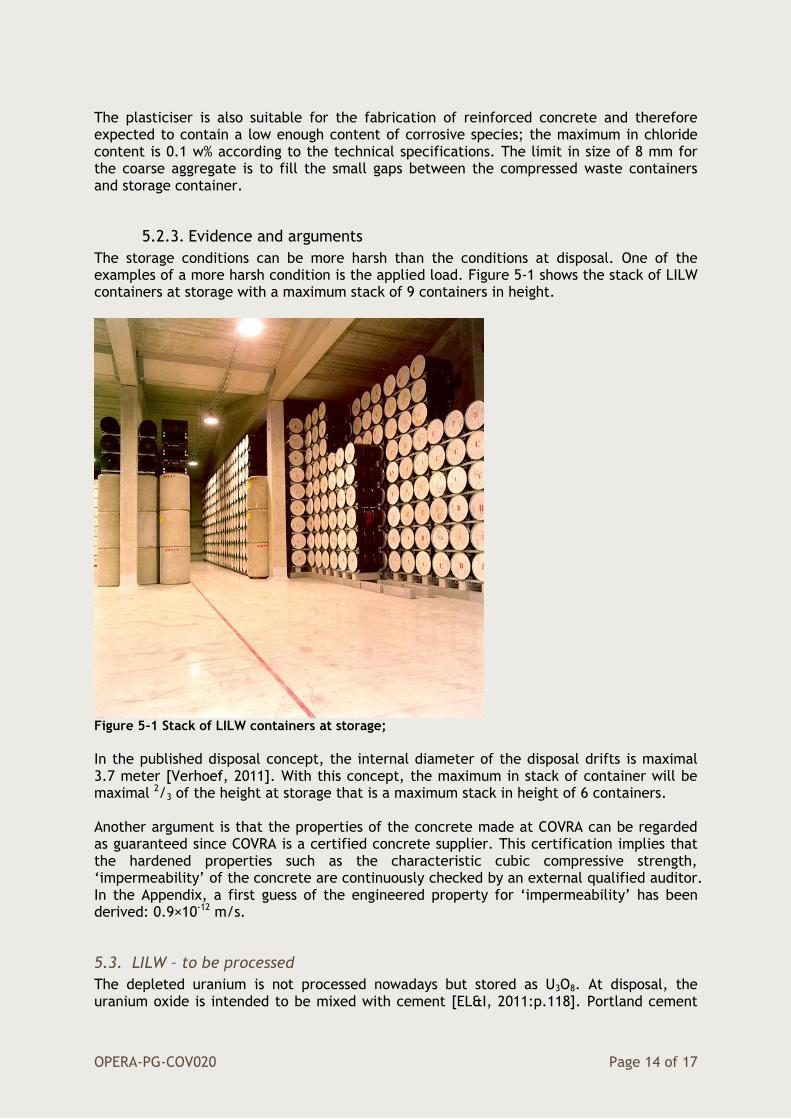
The storage conditions can be more harsh than the conditions at disposal. One of the examples of a more harsh condition is the applied load. Figure 5-1 shows the stack of LILW containers at storage with a maximum stack of 9 containers in height.
Figure 5-1 Stack of LILW containers at storage;
In the published disposal concept, the internal diameter of the disposal drifts is maximal 3.7 meter [Verhoef, 2011]. With this concept, the maximum in stack of container will be maximal 2/3 of the height at storage that is a maximum stack in height of 6 containers. Another argument is that the properties of the concrete made at COVRA can be regarded as guaranteed since COVRA is a certified concrete supplier. This certification implies that the hardened properties such as the characteristic cubic compressive strength, ‘impermeability’ of the concrete are continuously checked by an external qualified auditor. In the Appendix, a first guess of the engineered property for ‘impermeability’ has been derived: 0.9×10⁻¹² m/s.
5.3. LILW – to be processed
The depleted uranium is not processed nowadays but stored as U3O8. At disposal, the uranium oxide is intended to be mixed with cement [EL&I, 2011:p.118]. Portland cement

OPERA-PG-COV020 Page 15 of 17
with limestone as aggregates is proposed as the containment of depleted uranium because sufficient calcium would then be available to react with traces of UF6 and precipitate as stable minerals [Kienzler, 2013:p.32]. Table 5-3 shows the suggested composition in which the stored U3O8 is used as aggregate. Table 5-3 Composition concrete for containment of TENORM (U3O8)
Component/ parameter
Type
Cement CEM I/42.5 N HS LA (LH) 365 kg m-3
Water - 175 kg m-3
Plasticiser TM OFT-II B84/39 CON. 35% (BT-SPL)
3.3 kg m-3
Fine aggregate U3O8: 0-4 mm 2664 kg m-3
Coarse aggregate
Limestone: 2-8 mm 911 kg m-3
w/c Property 0.48
N Usual initial strength, HS High Sulphate resistance, LA Low Alkali content , (LH Low Hydration heat) The uraniumoxide - portland concrete mixture will be contained in Konrad Type II concrete cubical containers for disposal [Verhoef, 2011a]. These containers are manufactured from sheet steel of at least 3 mm thickness and the total maximum weight is 20.000 kg [Lange, 1992:p.7]. The same plasticiser as used for the concrete made by COVRA is suggested because this plasticiser is expected to contain a low enough content of corrosive species for the sheet steel used for the Konrad container. Limestone is added as a coarse aggregate because a larger content in U3O8 as aggregates is expected to exceed the maximum in weight. Filling the Konrad Type II containers until 100% with the suggested composition is not expected to exceed the maximum in weight. An option is to include a concrete liner [Eisenwerk Bassum, 2014] but this inclusion is not considered to be necessary for this purpose due to sufficient shielding by sheet steel and made concrete during the operational phase e.g. transport.
OPERA-PG-COV020 Page 16 of 17
6. References [Barnichon, 2000] Barnichon JD, Neerdael B, Grupa J, Vervoort A, CORA Project TRUCK II (CORA 18 in overview report) SCK CEN R-3409 (2000) 1-100. [Bastiaens, 2003] Bastianes W, Bernier F, Buynes M, Demarche M, Li XL, Linotte J-M, Verstricht J, The extension of the HADES underground research facility at Mol, Belgium, EURIDICE report 03-294 (2003) 1-98. [Bel, 2005] Bel J, Van Cotthem A, De Bock C, Construction, Operation and closure of the Belgian repository for long-lived waste, 10th International Conference on Environmental Remediation of Radioactive Waste Management, ICEM05 Glasgow, Scotland, 1-7. [Berckmans, 2013] Berckmans A, Boulanger D, Brassinnes S, Capouet M, Depaus C, Dorado Lopez E, Gambi A, Gens R, Sillen X, Van Baelen H, Van Geet M, Van Marcke P, Wacquier W, Wouters L, Harvey L, Wickham S, Pirot V, ONDRAF/NIRAS Research, Development and Demonstration (RD&D) Plan NIROND-TR 2013-12 E (2013) 1-411. [Betonpocket, 2009] Book of reference for concrete made by the Dutch companies ENCI, Mebin, Sagrex and NBC (2009) 1-288. [Bock, 2008] De Bock C, Bosgiraud J-M, Weber H, Rothfuchs T, Verstricht J, Breen B, Johnson M, Achievements of the ESDRED project in buffer construction technology, Proceedings EURADWASTE 2008, Seventh European Conference on the management and disposal of radioactive waste held in Luxembourg EUR 24040 (2009) 239-258. [Eisenwerk Bassum, 2014] Present manufacturer of Konrad type II containers. [Geet, 2006] Van Geet M, Wang L, De Boever P, De Craen M, Geochemical boundary conditions relevant for assessing corrosion processes for the supercontainer design,
SCKCEN-ER-14 (2006) 1-33. [Humbeeck, 2007] Van Humbeeck H, De Bock C, Bastiaens W, Demonstrating the Construction and Backfilling feasibility of the supercontainer design for HLW, Proceedings RepoSafe, International Conference on Radioactive Waste Disposal in Geological Formations held in Braunschweig November 6 – 9 2007, 336-345. [Humbeeck, 2008] Van Humbeeck H, Bastiaens W, De Bock C, Van Cotthem A, Experimental programme to demonstrate the viability of the supercontainer concept for HLW, International Conference Underground Disposal Unit Design & Emplacement Processes for a Deep Geological Repository held in Prague June 16-18 2008, 4:1-10. [IAEA, 2012] ] International Atomic Energy Agency, The safety case and safety assessments for the disposal of radioactive waste, Specific Safety Guide, No. SSG-23 (2012) 1-120. [Kienzler, 2013] Kienzler B, Altmaier M, Bube C, Metz V, Radionuclide source term for irradiated fuel from prototype, research and education reactors, for waste forms with negligible heat generation and for uranium tails, KIT Scientific reports 7635 (2013) 1-66. [Lange, 1992] Lange F, Gründler D, Schwarz G, Konrad transport study: safety analysis of the transport of radioactive waste to the Konrad waste disposal site, International Journal of Radioactive Materials transport, 3[4] (1992) 1-66.
OPERA-PG-COV020 Page 17 of 17
[Rijkers, 1998] Rijkers RHB, Huisman DJ, de Lange G, Weijers JP, Witmans-Parker N, Inventarisatie geomechanische, geochemische en geohydrologische eigenschappen en Tertiare kleipakketten – CAR (tertiary Clay As potential host Rock) Fase II (CORA 16 in overview report), NITG-98-90-B (1998) 1-73. [Verhoef, 2011a] Verhoef EV, Neeft EAC, Grupa JB, Poley AD, Outline of a disposal concept in clay, OPERA-PG-COV008 (2011) 1-17. [Verhoef, 2011b] Verhoef EV, Schröder TJ, OPERA Research Plan-Section I The Safety case, OPERA-PG-COV004 (2011) 1-24. [NV Westerscheldetunnel, 2014] A representative composition of the prefabricated concrete segments used for the Westerscheldetunnel has been provided by e-mail on 19 March 2014. [Wickham, 2008] Wickham S, Evolution of the near-field of the ONDRAF/NIRAS repository concept for category C-wastes, NIROND-TR 2007-07E (2008) 1-140.
OPERA-PG-COV020 Page 1 of 3
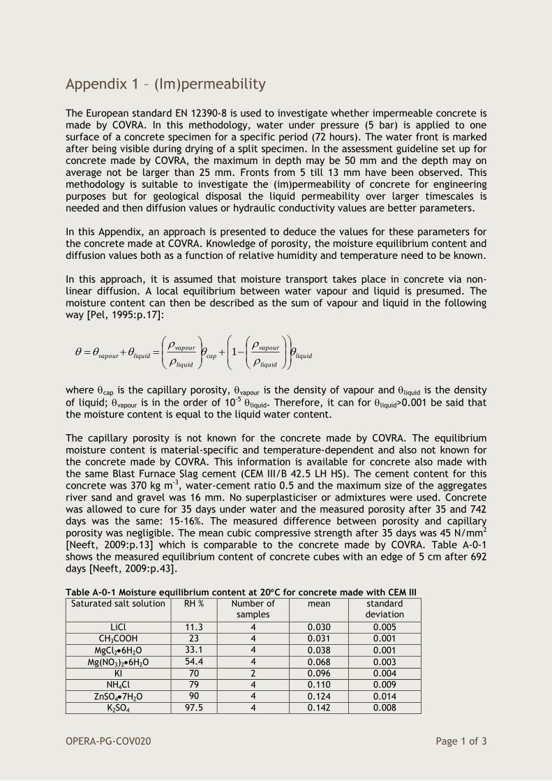
Appendix 1 – (Im)permeability The European standard EN 12390-8 is used to investigate whether impermeable concrete is made by COVRA. In this methodology, water under pressure (5 bar) is applied to one surface of a concrete specimen for a specific period (72 hours). The water front is marked after being visible during drying of a split specimen. In the assessment guideline set up for concrete made by COVRA, the maximum in depth may be 50 mm and the depth may on average not be larger than 25 mm. Fronts from 5 till 13 mm have been observed. This methodology is suitable to investigate the (im)permeability of concrete for engineering purposes but for geological disposal the liquid permeability over larger timescales is needed and then diffusion values or hydraulic conductivity values are better parameters. In this Appendix, an approach is presented to deduce the values for these parameters for the concrete made at COVRA. Knowledge of porosity, the moisture equilibrium content and diffusion values both as a function of relative humidity and temperature need to be known. In this approach, it is assumed that moisture transport takes place in concrete via non-linear diffusion. A local equilibrium between water vapour and liquid is presumed. The moisture content can then be described as the sum of vapour and liquid in the following way [Pel, 1995:p.17]:
liquid
liquid
vapour
cap
liquid
vapour
liquidvapour
1
where cap is the capillary porosity, vapour is the density of vapour and liquid is the density
of liquid; vapour is in the order of 10-5 liquid. Therefore, it can for liquid>0.001 be said that the moisture content is equal to the liquid water content. The capillary porosity is not known for the concrete made by COVRA. The equilibrium moisture content is material-specific and temperature-dependent and also not known for the concrete made by COVRA. This information is available for concrete also made with the same Blast Furnace Slag cement (CEM III/B 42.5 LH HS). The cement content for this concrete was 370 kg m-3, water-cement ratio 0.5 and the maximum size of the aggregates river sand and gravel was 16 mm. No superplasticiser or admixtures were used. Concrete was allowed to cure for 35 days under water and the measured porosity after 35 and 742 days was the same: 15-16%. The measured difference between porosity and capillary porosity was negligible. The mean cubic compressive strength after 35 days was 45 N/mm2 [Neeft, 2009:p.13] which is comparable to the concrete made by COVRA. Table A-0-1 shows the measured equilibrium content of concrete cubes with an edge of 5 cm after 692 days [Neeft, 2009:p.43]. Table A-0-1 Moisture equilibrium content at 20C for concrete made with CEM III
Saturated salt solution RH % Number of samples
mean standard deviation
LiCl 11.3 4 0.030 0.005
CH3COOH 23 4 0.031 0.001
MgCl26H2O 33.1 4 0.038 0.001
Mg(NO3)26H2O 54.4 4 0.068 0.003
KI 70 2 0.096 0.004
NH4Cl 79 4 0.110 0.009
ZnSO47H2O 90 4 0.124 0.014
K2SO4 97.5 4 0.142 0.008

OPERA-PG-COV020 Page 2 of 3
The fitted equilibrium moisture content as a function of RH for the investigated concrete with Blast Furnace Slag cement is [Neeft, 2009:p.46]:
RHeRHC 011.0)01.007.0(05.0),20(
with RH in %. Theoretically, at RH=0%, the moisture content should be 0 and the fitting almost achieves this value. Similarly as the moisture content, a local equilibrium between water vapour and liquid is presumed and the diffusion coefficient for moisture can be expressed as the sum of the diffusion of vapour and liquid. This exercise is performed by Pel and the moisture transport can be approximated into a non-linear diffusion equation [Pel, 1995:p.17]:
D
t
where D is the moisture diffusion coefficient. For most investigated building materials, the overall behaviour of the moisture diffusion coefficient shows an exponential behaviour. The description of the moisture diffusion coefficient for the movement of water in soil published in 1958 by Gardner and Mayhugh can also be used for porous building materials [Pel, 1995:p.56]:
capcap
eDD
0
where D0 and β are material-dependent properties. D0 was taken 1×10-11 m2/s since this value is the minimum value ever measured for concrete [Reinhardt, 2003]. The measured desorption and absorption at eighth different values in relative humidity could be
simulated well with a single value for β namely 2 at 20C for the same concrete with Blast Furnace slag cement from which the moisture equilibrium content is measured [Neeft, 2009;p.49,56]. For the simulation of COVRA samples using the European standard EN 12390-8, the non-linear diffusion equation is solved with
=cap for the surface to which the water pressure of 5 bar is applied;
=(T,RH) for the non-exposed surfaces;
the initial ratio between the moisture content and capillary porosity after curing is assumed to be 0.90 (this value was measured for the investigated concrete).
Two-dimensional solutions could be obtained (the investigated COVRA samples used for the test are too large to obtain a solution using solvers available in COMSOL in three
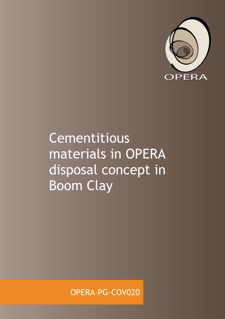
dimensions). Figure A-1 shows the solution presuming the measurement performed at 20C for a relative humidity of 40% and 80%; people usually work within this range in humidity.
OPERA-PG-COV020 Page 3 of 3
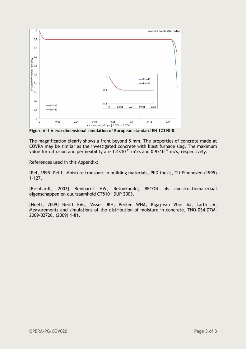
Figure A-1 A two-dimensional simulation of European standard EN 12390-8.
The magnification clearly shows a front beyond 5 mm. The properties of concrete made at COVRA may be similar as the investigated concrete with blast furnace slag. The maximum value for diffusion and permeability are 1.4×10⁻¹¹ m2/s and 0.9×10⁻¹² m/s, respectively. References used in this Appendix: [Pel, 1995] Pel L, Moisture transport in building materials, PhD thesis, TU Eindhoven (1995) 1-127. [Reinhardt, 2003] Reinhardt HW, Betonkunde, BETON als constructiemateriaal eigenschappen en duurzaamheid CT5101 DUP 2003. [Neeft, 2009] Neeft EAC, Visser JKH, Peelen WHA, Bigaj-van Vliet AJ, Larbi JA, Measurements and simulations of the distribution of moisture in concrete, TNO-034-DTM-2009-02726, (2009) 1-81.

OPERA-PG-COV020 Page 1 of 3