Cementing Deepwater Wells - 石油技術協会 · zDeepwater Cementing Technology. Page 3 24 Jun....
42
Cementing Deepwater Wells Well Services – Schlumberger Junichi Hagura
Transcript of Cementing Deepwater Wells - 石油技術協会 · zDeepwater Cementing Technology. Page 3 24 Jun....

Cementing Deepwater Wells
Well Services – SchlumbergerJunichi Hagura
Page 224 Jun. 2003
Presentation outline
Specific deepwater challenges & Overview of geo-hazards
Deepwater cement slurries requirements
Deepwater Cementing Technology
Page 324 Jun. 2003
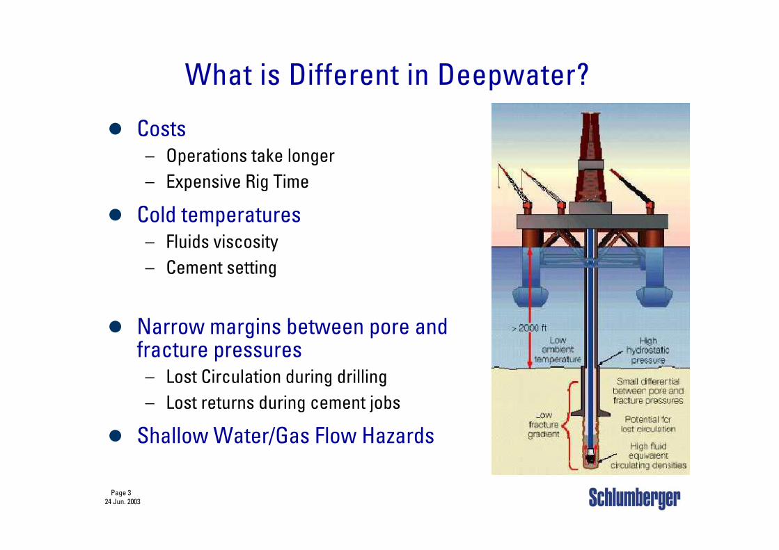
What is Different in Deepwater?
Costs– Operations take longer– Expensive Rig Time
Cold temperatures– Fluids viscosity– Cement setting
Narrow margins between pore and fracture pressures
– Lost Circulation during drilling– Lost returns during cement jobs
Shallow Water/Gas Flow Hazards
Page 424 Jun. 2003
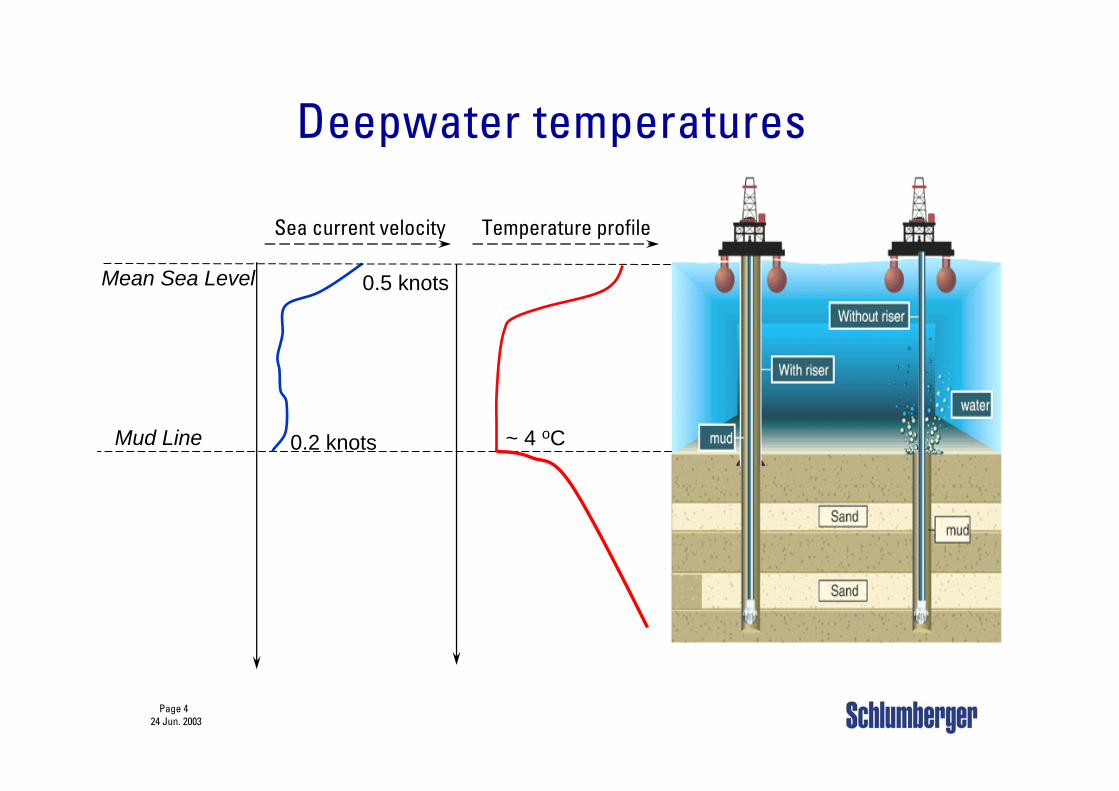
Deepwater temperatures
0.5 knots
0.2 knots ~ 4 oCMud Line
Mean Sea Level
Sea current velocity Temperature profile
Page 524 Jun. 2003
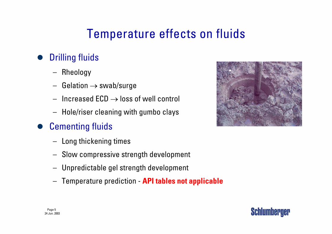
Temperature effects on fluids
Drilling fluids– Rheology
– Gelation → swab/surge
– Increased ECD → loss of well control
– Hole/riser cleaning with gumbo clays
Cementing fluids – Long thickening times
– Slow compressive strength development
– Unpredictable gel strength development
– Temperature prediction - API tables not applicable
Page 624 Jun. 2003
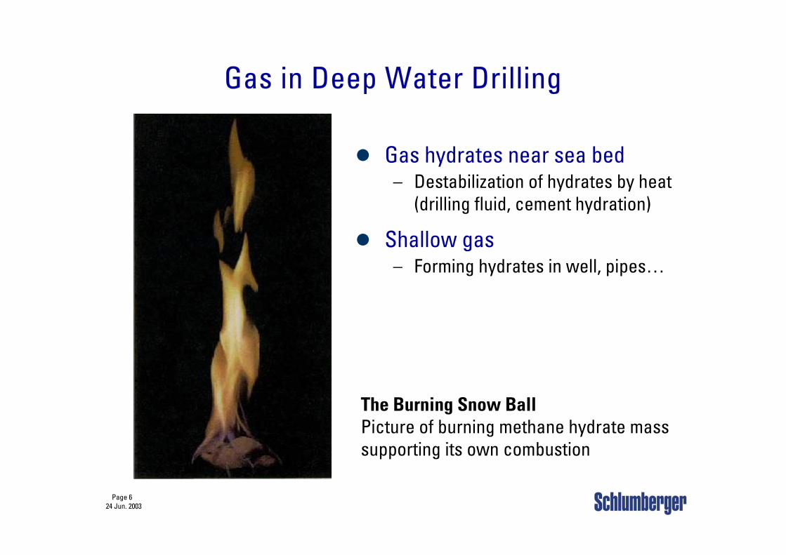
Gas in Deep Water Drilling
Gas hydrates near sea bed– Destabilization of hydrates by heat
(drilling fluid, cement hydration)
Shallow gas– Forming hydrates in well, pipes…
The Burning Snow BallPicture of burning methane hydrate mass supporting its own combustion
Page 724 Jun. 2003
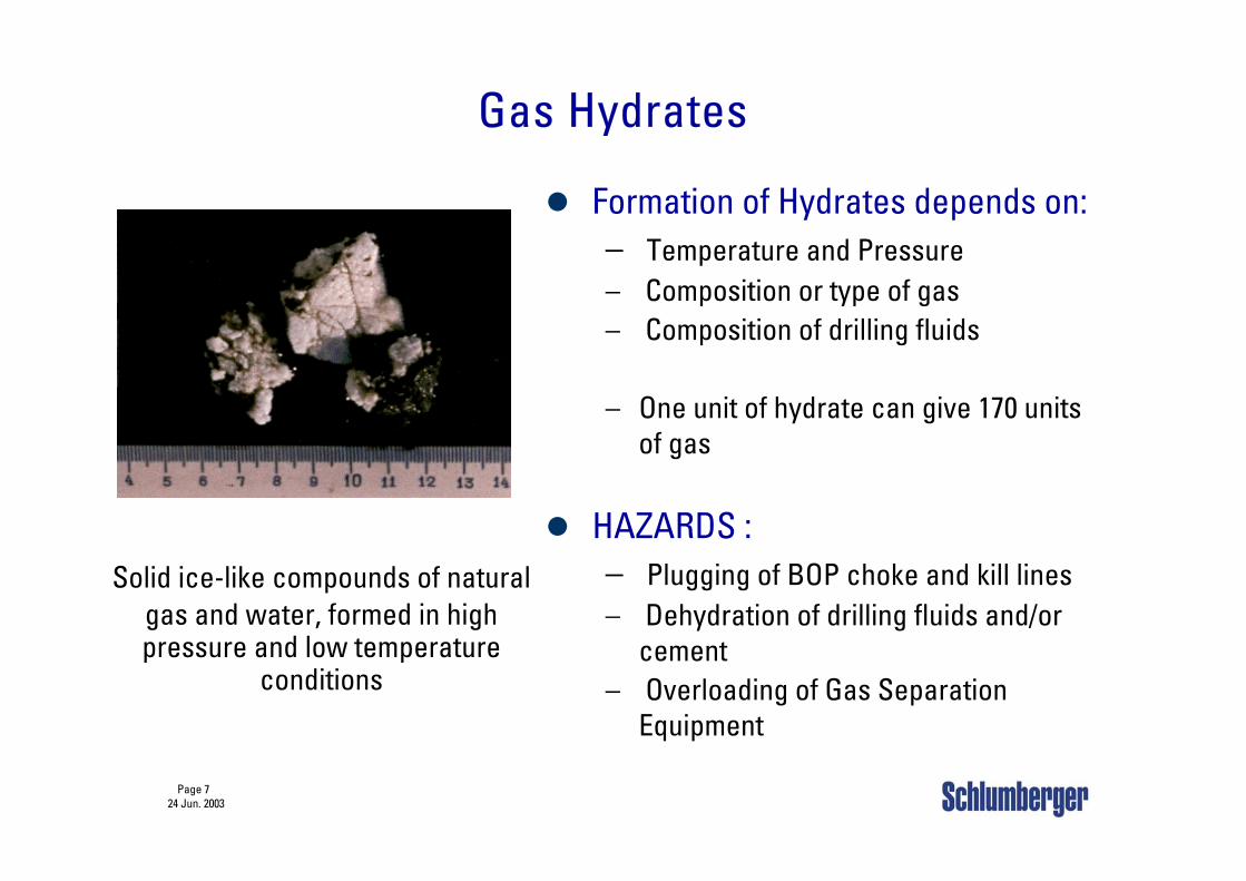
Gas Hydrates
Solid ice-like compounds of naturalgas and water, formed in high pressure and low temperature
conditions
Formation of Hydrates depends on:– Temperature and Pressure– Composition or type of gas– Composition of drilling fluids
– One unit of hydrate can give 170 units of gas
HAZARDS :– Plugging of BOP choke and kill lines– Dehydration of drilling fluids and/or
cement– Overloading of Gas Separation
Equipment
Page 824 Jun. 2003
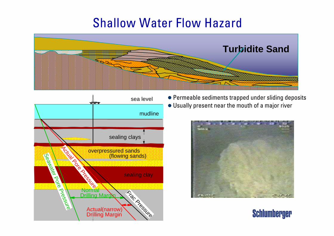
Shallow Water Flow Hazard
Turbidite Sand
Permeable sediments trappedunder sliding deposits
mudline
sea level
overpressured sands(flowing sands)
sealing clay
sealing clays
Seawater Pore Pressure
Normal Drilling Margin
Actual Pore Pressure
Frac Pressure
Actual (narrow)Drilling Margin
Permeable sediments trapped under sliding depositsUsually present near the mouth of a major river
Page 924 Jun. 2003
Shallow Water Flow Problems
Safety and environmental concernsFlow during drilling or cement
– Jeopardizes template stability
Lost circulation during drilling or cement placement– Well Control
Excessive hole washouts– Mud removal difficult
Destabilization of near well bore formations– Integrity of BOP and Riser
Breakthrough to the seafloor– Loss of drive pipe, conductor or the well
Page 1024 Jun. 2003
Deepwater Cementing
Specific deepwater challenges & Overview of geo-hazards
Deepwater cement slurries requirements– Objectives and challenges for DW cements– Cement requirements for shallow
water/gas flow hazards
Deepwater Cementing Technology
Page 1124 Jun. 2003
Deep Water Cementing:Objectives & Requirements
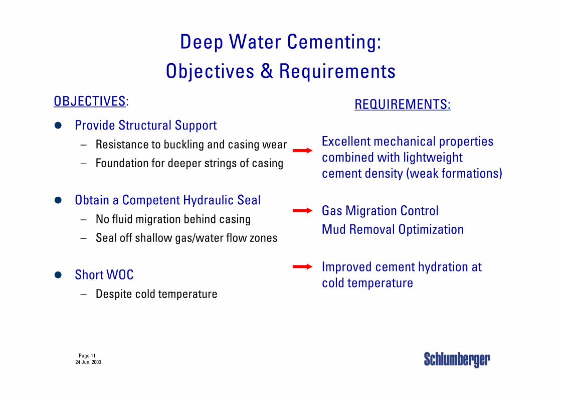
OBJECTIVES:
Provide Structural Support– Resistance to buckling and casing wear
– Foundation for deeper strings of casing
Obtain a Competent Hydraulic Seal– No fluid migration behind casing
– Seal off shallow gas/water flow zones
Short WOC– Despite cold temperature
Excellent mechanical properties combined with lightweight cement density (weak formations)
Gas Migration ControlMud Removal Optimization
Improved cement hydration at cold temperature
REQUIREMENTS:
Page 1224 Jun. 2003
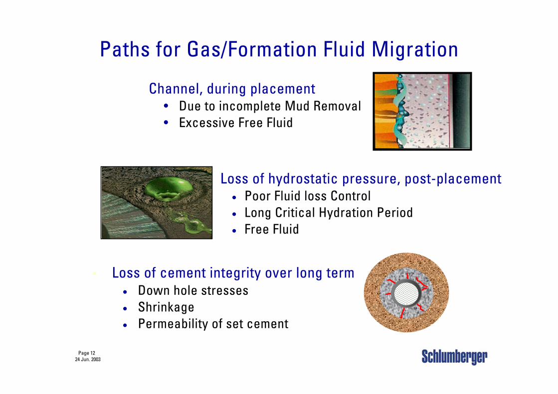
Paths for Gas/Formation Fluid Migration
Channel, during placement• Due to incomplete Mud Removal• Excessive Free Fluid
Loss of hydrostatic pressure, post-placement• Poor Fluid loss Control• Long Critical Hydration Period• Free Fluid
Loss of cement integrity over long term• Down hole stresses• Shrinkage• Permeability of set cement
Page 1324 Jun. 2003
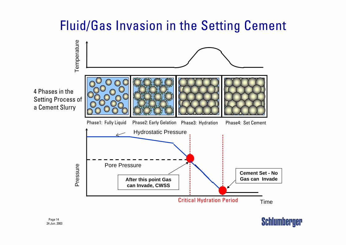
Mechanism for fluid/gas migration in the cement before it sets
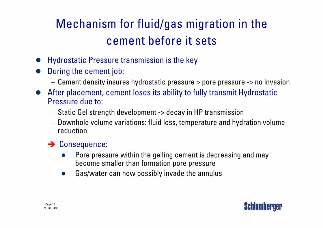
Hydrostatic Pressure transmission is the keyDuring the cement job:
– Cement density insures hydrostatic pressure > pore pressure -> no invasionAfter placement, cement loses its ability to fully transmit Hydrostatic Pressure due to:– Static Gel strength development -> decay in HP transmission– Downhole volume variations: fluid loss, temperature and hydration volume
reduction
Consequence:Pore pressure within the gelling cement is decreasing and may become smaller than formation pore pressureGas/water can now possibly invade the annulus
Page 1424 Jun. 2003
Fluid/Gas Invasion in the Setting Cement
After this point Gas can Invade, CWSSP
ress
ure Pore Pressure
Hydrostatic Pressure
Tem
pera
ture
4 Phases in the Setting Process of a Cement Slurry
Phase1: Fully Liquid Phase2: Early Gelation Phase3: Hydration Phase4: Set Cement
Critical Hydration Period
Cement Set - No Gas can Invade
Time
Page 1524 Jun. 2003
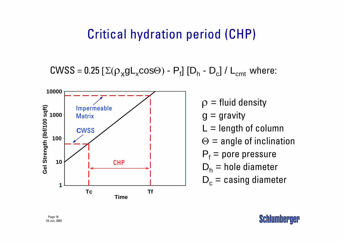
Definition of termsStatic Gel Strength (SGS)
– Measure of the attractive forces between the particles of a fluid under static (non flowing) conditions. The measure of these same attractive forces of a fluid under flowing (dynamic) conditions is what is commonly referred to as “yield point” of a slurry.
Critical Wall Shear Stress (CWSS)– A measure of the amount of gel strength that must develop to cause
hydrostatic decay to allows gas entry
– Not a slurry property
– Totally dependent on well geometry & pressures
Critical Hydration Period (CHP)– Period of time when gas/water can enter the annulus
– Begins when CWSS is achieved
– Ends when matrix permeability is sufficient to stop flow
Page 1624 Jun. 2003
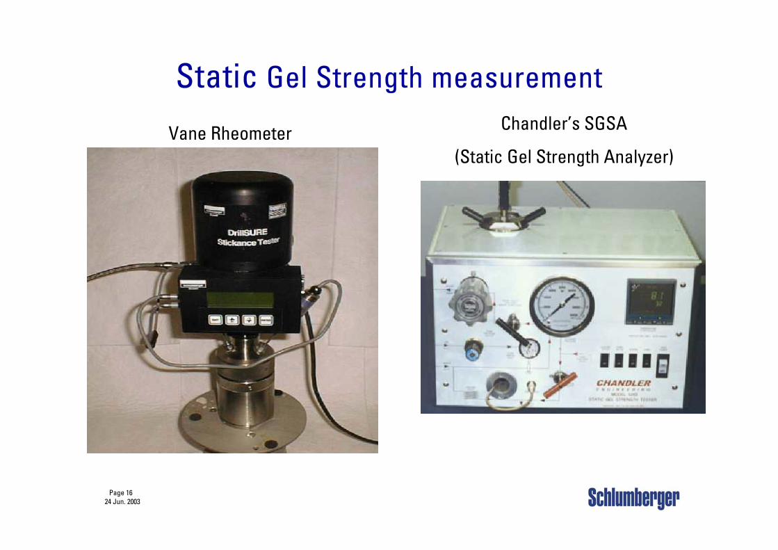
Static Gel Strength measurement
Vane Rheometer Chandler’s SGSA
(Static Gel Strength Analyzer)
Page 1724 Jun. 2003
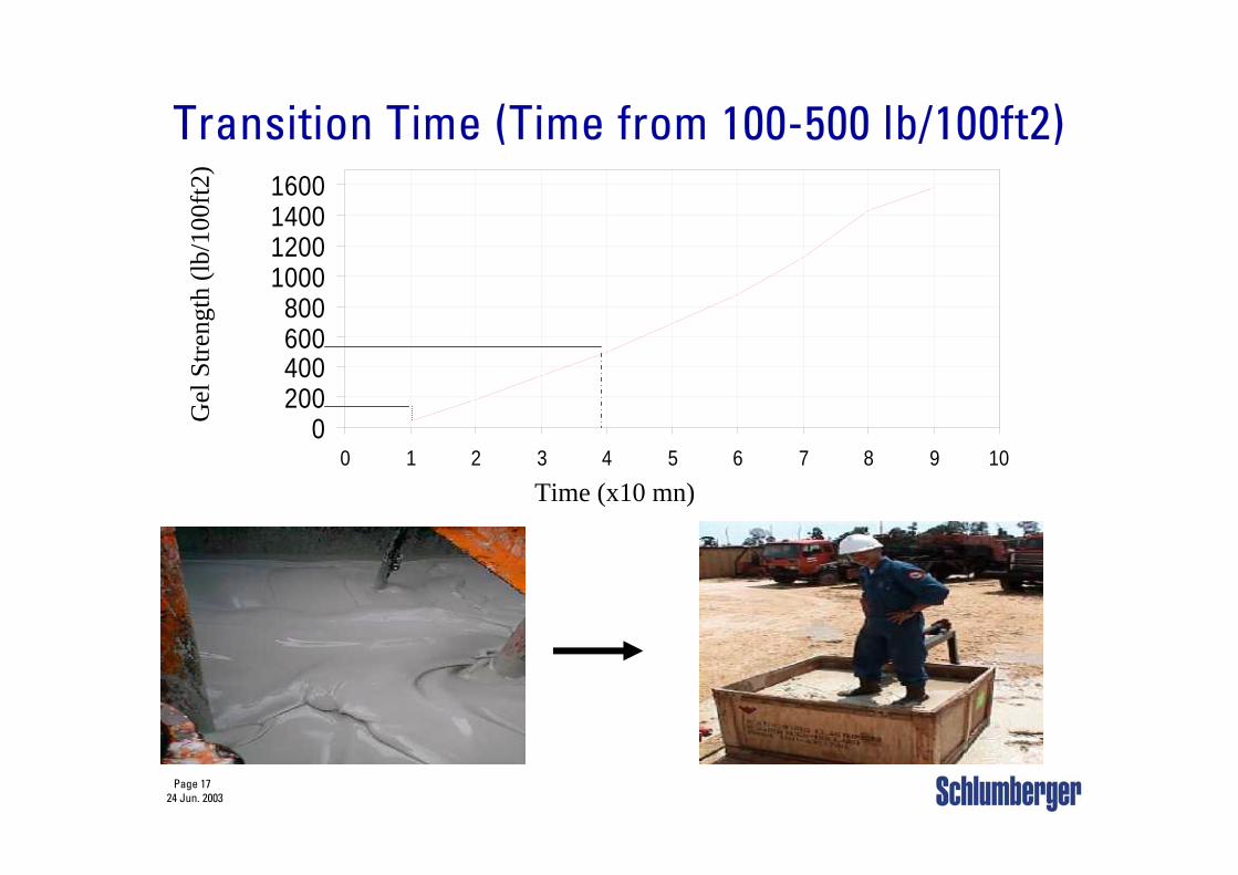
0200400600800
1000120014001600
0 1 2 3 4 5 6 7 8 9 10
Transition Time (Time from 100-500 lb/100ft2)
Time (x10 mn)
Gel
Stre
ngth
(lb/
100f
t2)
Page 1824 Jun. 2003
Critical hydration period (CHP)
CWSS = 0.25 [Σ(ρxgLxcosΘ) - Pf] [Dh - Dc] / Lcmt where:
ρ = fluid densityg = gravityL = length of columnΘ = angle of inclinationPf = pore pressureDh = hole diameterDc = casing diameter
1
10
100
1000
10000
Time
Gel
Str
engt
h (lb
f/100
sqf
t)
CWSS
TfTc
CHP
ImpermeableMatrix
Page 1924 Jun. 2003
Controlling shallow water/gas flowsSlurry requirements
Low density slurry (low frac gradient)
Excellent fluid loss control (< 50 ml)
No free water/sedimentation (no path for gas/fluid)
Rapid setting at low temperature (WOC time)
Short critical hydration period (gas/fluid migration)
Low set cement permeability (no path for gas/fluid)
Page 2024 Jun. 2003
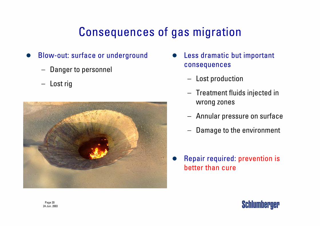
Consequences of gas migration
Less dramatic but important consequences
– Lost production
– Treatment fluids injected in wrong zones
– Annular pressure on surface
– Damage to the environment
Repair required: prevention is better than cure
Blow-out: surface or underground
– Danger to personnel
– Lost rig
Page 2124 Jun. 2003
Deepwater Cementing
Specific deepwater challenges & Overview of geo-hazards
Deepwater cement slurries requirements
Deepwater Cementing Technology– Liquid additives for cold temperatures– Foamed cement– PSD Slurry for Deepwater
Page 2224 Jun. 2003
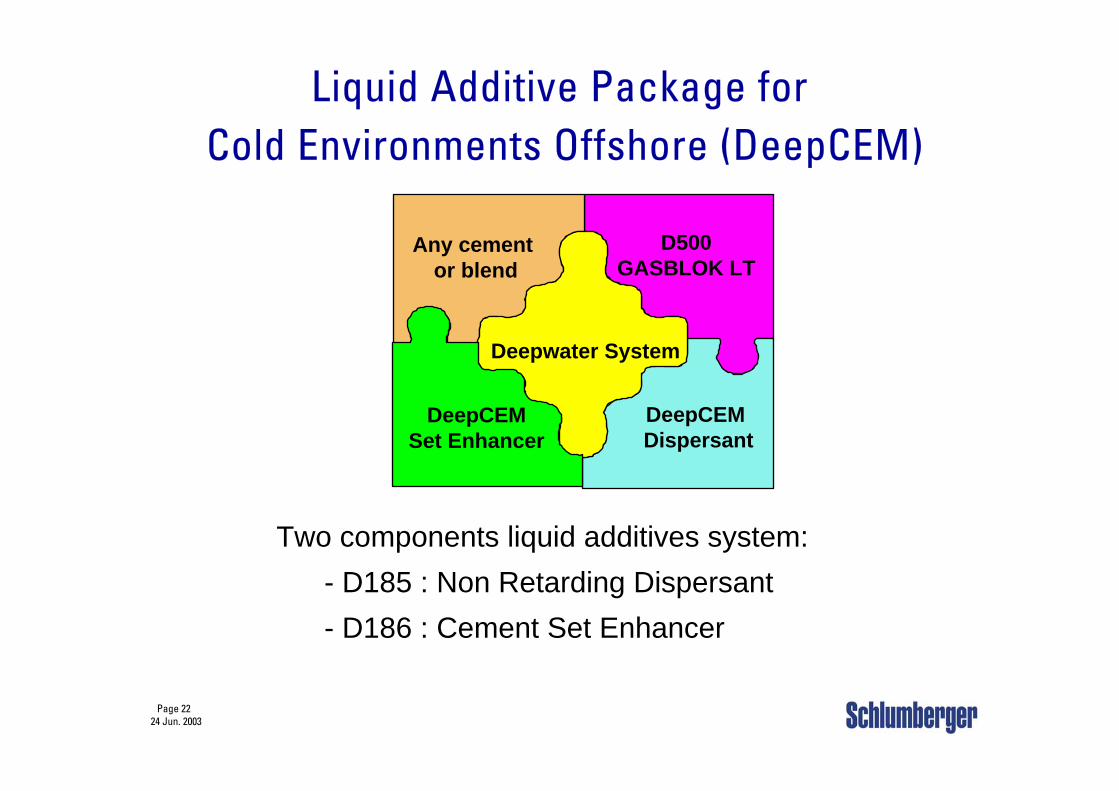
D500GASBLOK LT
Any cement or blend
DeepCEM Dispersant
Deepwater System
DeepCEMSet Enhancer
Liquid Additive Package forCold Environments Offshore (DeepCEM)
Two components liquid additives system:- D185 : Non Retarding Dispersant- D186 : Cement Set Enhancer
Page 2324 Jun. 2003
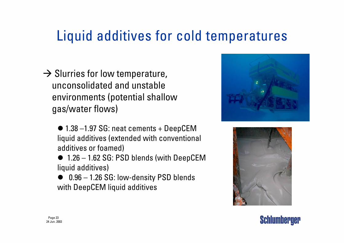
Liquid additives for cold temperatures
Slurries for low temperature, unconsolidated and unstable environments (potential shallow gas/water flows)
1.38 –1.97 SG: neat cements + DeepCEM liquid additives (extended with conventional additives or foamed)
1.26 – 1.62 SG: PSD blends (with DeepCEM liquid additives)
0.96 – 1.26 SG: low-density PSD blends with DeepCEM liquid additives
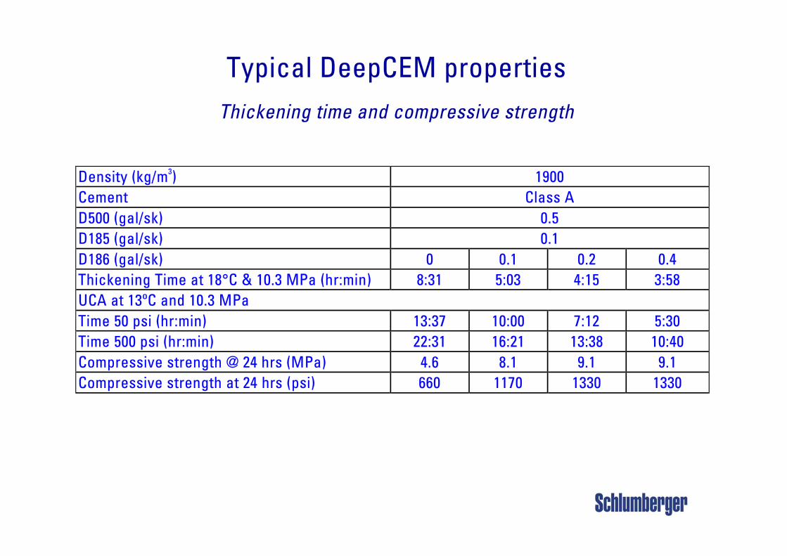
Typical DeepCEM propertiesThickening time and compressive strength
Density (kg/m3) 1900 Cement Class A D500 (gal/sk) 0.5 D185 (gal/sk) 0.1 D186 (gal/sk) 0 0.1 0.2 0.4 Thickening Time at 18°C & 10.3 MPa (hr:min) 8:31 5:03 4:15 3:58 UCA at 13ºC and 10.3 MPa Time 50 psi (hr:min) 13:37 10:00 7:12 5:30 Time 500 psi (hr:min) 22:31 16:21 13:38 10:40 Compressive strength @ 24 hrs (MPa) 4.6 8.1 9.1 9.1 Compressive strength at 24 hrs (psi) 660 1170 1330 1330
Page 2524 Jun. 2003
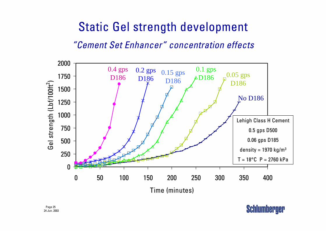
Static Gel strength development”Cement Set Enhancer” concentration effects
0
250
500
750
1000
1250
1500
1750
2000
0 50 100 150 200 250 300 350 400
Time (minutes)
Gel
str
engt
h (L
bf/1
00ft2 )
Lehigh Class H Cement
0.5 gps D500
0.06 gps D185
density = 1970 kg/m3
T = 18°C P = 2760 kPa
0.4 gpsD186
0.2 gpsD186
0.15 gpsD186
0.1 gpsD186 0.05 gps
D186
No D186
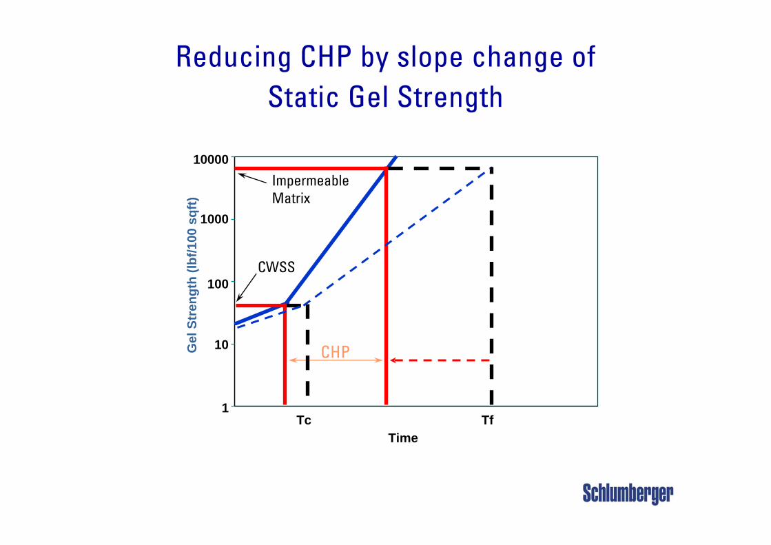
Reducing CHP by slope change ofStatic Gel Strength
1
10
100
1000
10000
Time
Gel
Str
engt
h (lb
f/100
sqf
t)
CWSS
TfTc
ImpermeableMatrix
CHP
Page 2724 Jun. 2003
Benefits of “Liquid additives for cold temperatures”
Improved setting characteristics in cold water
Effective shallow water and gas flow prevention (in combination with fluid loss or GASBLOK additive)
Simplified logistics
Quick static gel strength development (short transition time i.e. short time from 100 to 500 lb/100ft2 gel strength)
Fast compressive strength development– short WOC time before casing release
Compatible with any type of cement (foamed or non-foamed neat cements, PSD blends cements, etc..)
Page 2824 Jun. 2003
Foamed cement systems
Pro’s– Proven technique for controlling Shallow Water Flow– Adjustable slurry density (nitrogen controls density)– Flat displacement profile - good mud removal
Con’s– Equipment and personnel intensive– Variable deck load considerations– Relatively high permeability– Safety concerns with pumping energized fluids– Environmental impact of surfactants
Page 2924 Jun. 2003
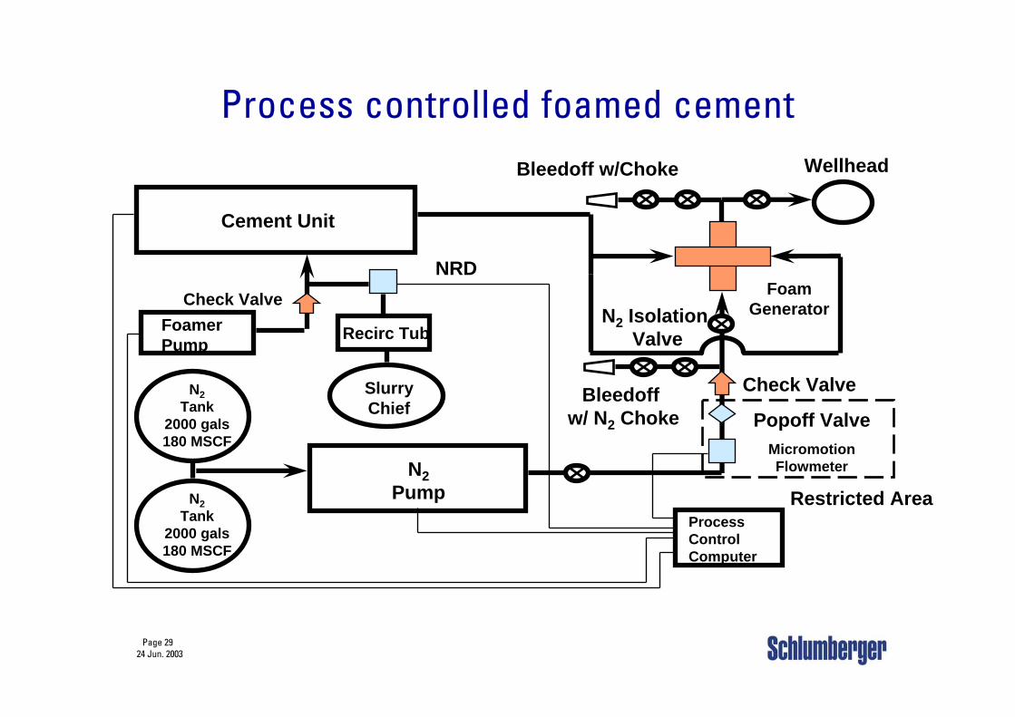
Process controlled foamed cement
Cement Unit
FoamerPump
N2Tank
2000 gals180 MSCF
N2Tank
2000 gals180 MSCF
N2Pump
ProcessControlComputer
Check Valve
FoamGenerator
Wellhead
Check Valve
MicromotionFlowmeter
SlurryChief
Recirc Tub
NRD
Popoff Valve
Bleedoff w/Choke
Restricted Area
Bleedoff w/ N2 Choke
N2 Isolation Valve
Page 3024 Jun. 2003
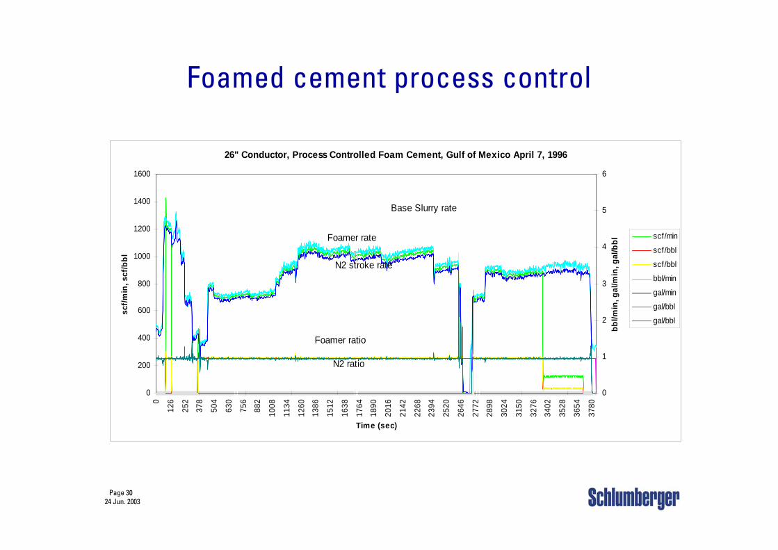
Foamed cement process control
26" Conductor, Process Controlled Foam Cement, Gulf of Mexico April 7, 1996
0
200
400
600
800
1000
1200
1400
1600
0
126
252
378
504
630
756
882
1008
1134
1260
1386
1512
1638
1764
1890
2016
2142
2268
2394
2520
2646
2772
2898
3024
3150
3276
3402
3528
3654
3780
Time (sec)
scf/m
in, s
cf/b
bl
0
1
2
3
4
5
6
bbl/m
in, g
al/m
in, g
al/b
bl
scf/min
scf/bbl
scf/bbl
bbl/min
gal/min
gal/bbl
gal/bbl
Base Slurry rate
N2 stroke rate
N2 ratio
Foamer ratio
Foamer rate
Page 3124 Jun. 2003
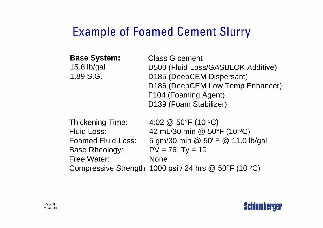
Base System:15.8 lb/gal1.89 S.G.
Class G cementD500 (Fluid Loss/GASBLOK Additive)D185 (DeepCEM Dispersant)D186 (DeepCEM Low Temp Enhancer)F104 (Foaming Agent)D139 (Foam Stabilizer)
Thickening Time:Fluid Loss:Foamed Fluid Loss:Base Rheology:Free Water:Compressive Strength
4:02 @ 50°F (10 oC)42 mL/30 min @ 50°F (10 oC)5 gm/30 min @ 50°F @ 11.0 lb/galPV = 76, Ty = 19None1000 psi / 24 hrs @ 50°F (10 oC)
Example of Foamed Cement Slurry
Page 3224 Jun. 2003
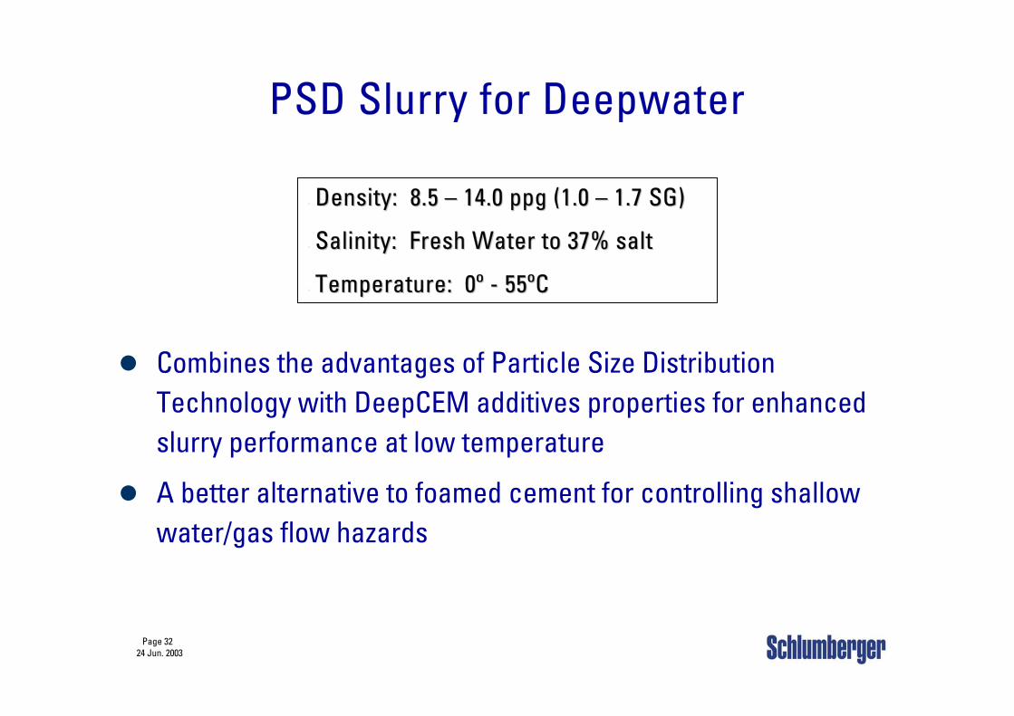
PSD Slurry for Deepwater
Combines the advantages of Particle Size Distribution Technology with DeepCEM additives properties for enhanced slurry performance at low temperature
A better alternative to foamed cement for controlling shallow water/gas flow hazards
•• Density: 8.5 Density: 8.5 –– 14.0 ppg (1.0 14.0 ppg (1.0 –– 1.7 SG)1.7 SG)
•• Salinity: Fresh Water to 37% saltSalinity: Fresh Water to 37% salt
•• Temperature: 0º Temperature: 0º -- 55ºC55ºC
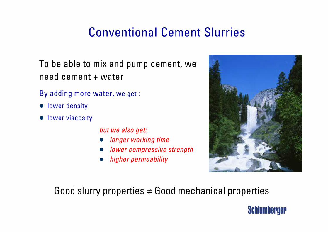
To be able to mix and pump cement, we need cement + water
By adding more water, we get :
lower density
lower viscosity
Conventional Cement Slurries
but we also get:longer working timelower compressive strengthhigher permeability
Good slurry properties ≠ Good mechanical properties
Page 3424 Jun. 2003
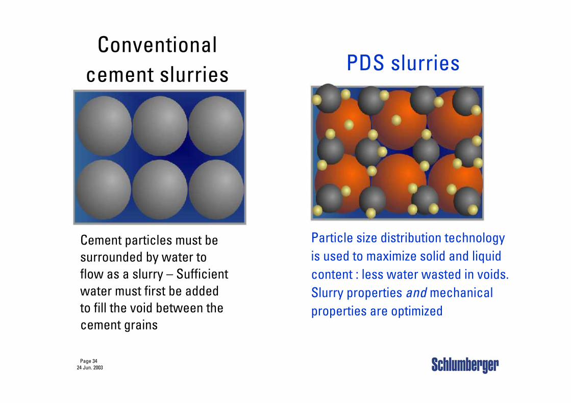
Conventional cement slurries
Cement particles must besurrounded by water toflow as a slurry – Sufficientwater must first be addedto fill the void between thecement grains
PDS slurries
Particle size distribution technologyis used to maximize solid and liquidcontent : less water wasted in voids.Slurry properties and mechanicalproperties are optimized
Page 3524 Jun. 2003
Advantages of “PSD Slurry for Deepwater”
“PSD Slurry for Deepwater” is particularly suitable at cementing weak deepwater zones with or without shallow water/gas flow hazards
– Simplified logistics and improved safety (no need for foamed cement
equipment to achieve low densities)
– Low densities maintain returns.
– Rapid strength development minimizes
waiting-on-cement (WOC) time.
– Combined with GASBLOK additive, It is an improvement over foam
cement for shallow water/gas flow hazards, thanks to its lower
permeability, very quick gel strength development and excellent
mechanical properties
Page 3624 Jun. 2003
“PSD Slurry for Deepwater” performance
For a typical “PSD Slurry for Deepwater” of 12.5 lbm/gal (1.50 SG)
– Slurry composition– PSD Blend (Porosity: 45%):– DeepCEM and GASBLOK LT Additives
– Slurry properties– Plastic viscosity: 105 cp– Yield point: 19 Ibf/100 ft2
– Fluid loss: 23 mL/30 min– Set cement
– Thickening time: 4:00 at 50°F (10 °C)– Transition time: 12 minutes (2 hrs conditioning)– Compressive strength at 50°F (10 °C) :
Time to 50 psi: 5:30Time to 500 psi: 13:20
Page 3724 Jun. 2003
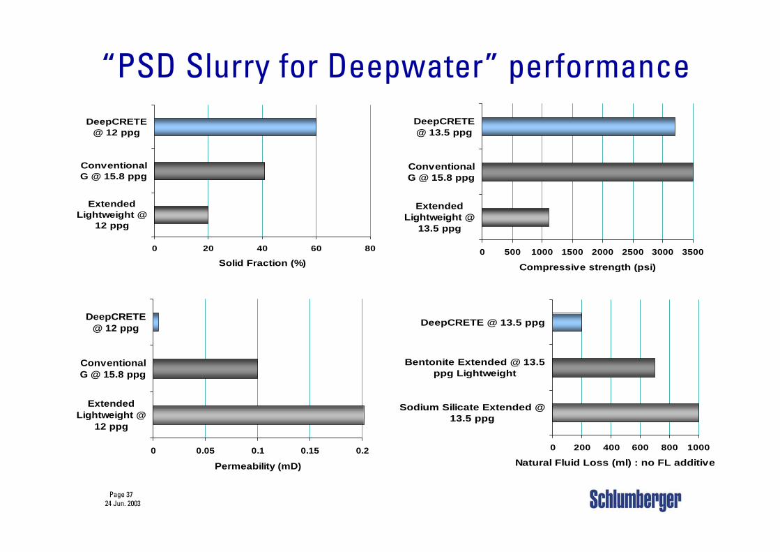
“PSD Slurry for Deepwater” performance
0 20 40 60 80
ExtendedLightweight @
12 ppg
ConventionalG @ 15.8 ppg
DeepCRETE@ 12 ppg
Solid Fraction (%)0 500 1000 1500 2000 2500 3000 3500
ExtendedLightweight @
13.5 ppg
ConventionalG @ 15.8 ppg
DeepCRETE@ 13.5 ppg
Compressive strength (psi)
0 0.05 0.1 0.15 0.2
ExtendedLightweight @
12 ppg
ConventionalG @ 15.8 ppg
DeepCRETE@ 12 ppg
Permeability (mD)
0 200 400 600 800 1000
Sodium Silicate Extended @13.5 ppg
Bentonite Extended @ 13.5ppg Lightweight
DeepCRETE @ 13.5 ppg
Natural Fluid Loss (ml) : no FL additive
Page 3824 Jun. 2003
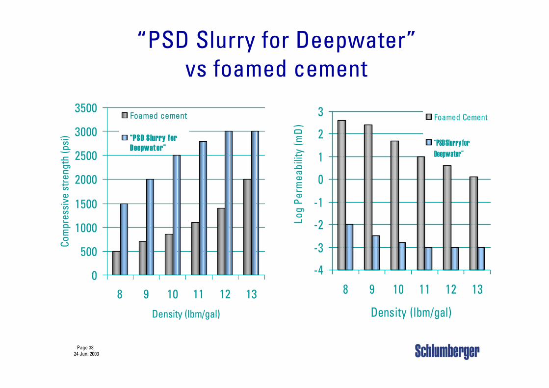
“PSD Slurry for Deepwater” vs foamed cement
0
500
1000
1500
2000
2500
3000
3500
8 9 10 11 12 13
Density (lbm/gal)
Com
pres
sive
str
engt
h (p
si)
Foamed cement
“PSD S lurry forDeepwat er”
-4
-3
-2
-1
0
1
2
3
8 9 10 11 12 13
Density (lbm/gal)Lo
g Pe
rmea
bilit
y (m
D)
Foamed Cement
“PSD Slurry forDeepwater”
Page 3924 Jun. 2003
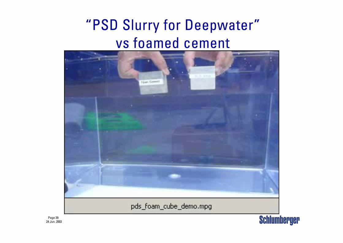
“PSD Slurry for Deepwater” vs foamed cement
Page 4024 Jun. 2003
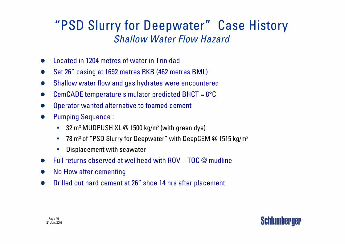
Located in 1204 metres of water in TrinidadSet 26” casing at 1692 metres RKB (462 metres BML) Shallow water flow and gas hydrates were encounteredCemCADE temperature simulator predicted BHCT = 8°COperator wanted alternative to foamed cementPumping Sequence :
• 32 m3 MUDPUSH XL @ 1500 kg/m3 (with green dye)
• 78 m3 of “PSD Slurry for Deepwater” with DeepCEM @ 1515 kg/m3
• Displacement with seawater
Full returns observed at wellhead with ROV – TOC @ mudlineNo Flow after cementingDrilled out hard cement at 26” shoe 14 hrs after placement
“PSD Slurry for Deepwater” Case HistoryShallow Water Flow Hazard
Page 4124 Jun. 2003
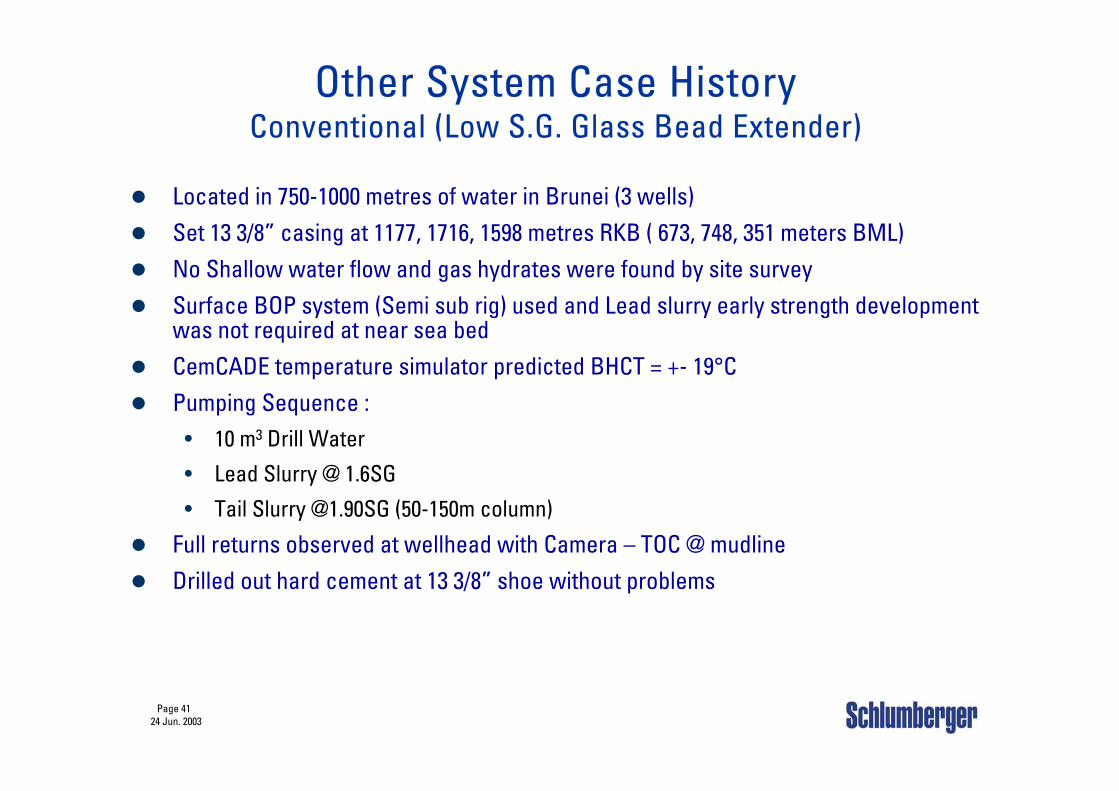
Located in 750-1000 metres of water in Brunei (3 wells)Set 13 3/8” casing at 1177, 1716, 1598 metres RKB ( 673, 748, 351 meters BML) No Shallow water flow and gas hydrates were found by site surveySurface BOP system (Semi sub rig) used and Lead slurry early strength development was not required at near sea bed CemCADE temperature simulator predicted BHCT = +- 19°CPumping Sequence :
• 10 m3 Drill Water
• Lead Slurry @ 1.6SG
• Tail Slurry @1.90SG (50-150m column)
Full returns observed at wellhead with Camera – TOC @ mudlineDrilled out hard cement at 13 3/8” shoe without problems
Other System Case HistoryConventional (Low S.G. Glass Bead Extender)
Page 4224 Jun. 2003
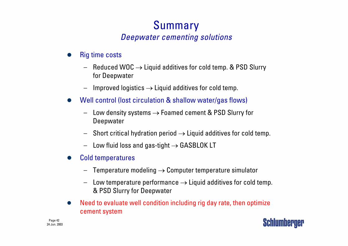
SummaryDeepwater cementing solutions
Rig time costs
– Reduced WOC → Liquid additives for cold temp. & PSD Slurry for Deepwater
– Improved logistics → Liquid additives for cold temp.
Well control (lost circulation & shallow water/gas flows)
– Low density systems → Foamed cement & PSD Slurry for Deepwater
– Short critical hydration period → Liquid additives for cold temp.
– Low fluid loss and gas-tight → GASBLOK LT
Cold temperatures
– Temperature modeling → Computer temperature simulator
– Low temperature performance → Liquid additives for cold temp. & PSD Slurry for Deepwater
Need to evaluate well condition including rig day rate, then optimize cement system