Cement Technology for Permanent P&A - Norsk olje og gass
20
Cement Technology for Permanent P&A Gunnar Lende, Technology Manager, Cementing Scandinavia Norway 2012 workshop Plug & Abandonment Forum
Transcript of Cement Technology for Permanent P&A - Norsk olje og gass

Cement Technology for Permanent P&A
Gunnar Lende,
Technology Manager,
Cementing Scandinavia
Norway 2012 workshop
Plug & Abandonment
Forum

2
Advances in cementing technology for permanent P&A
1. Sealant shrinkage during curing – Deal with it
2. Volume control on depleted well bullhead squeezes
3. Avoid section milling in overburden
4. Attacking conventional P&A critical path WOC time
5. Logging & evaluation
Topics in this presentation
3
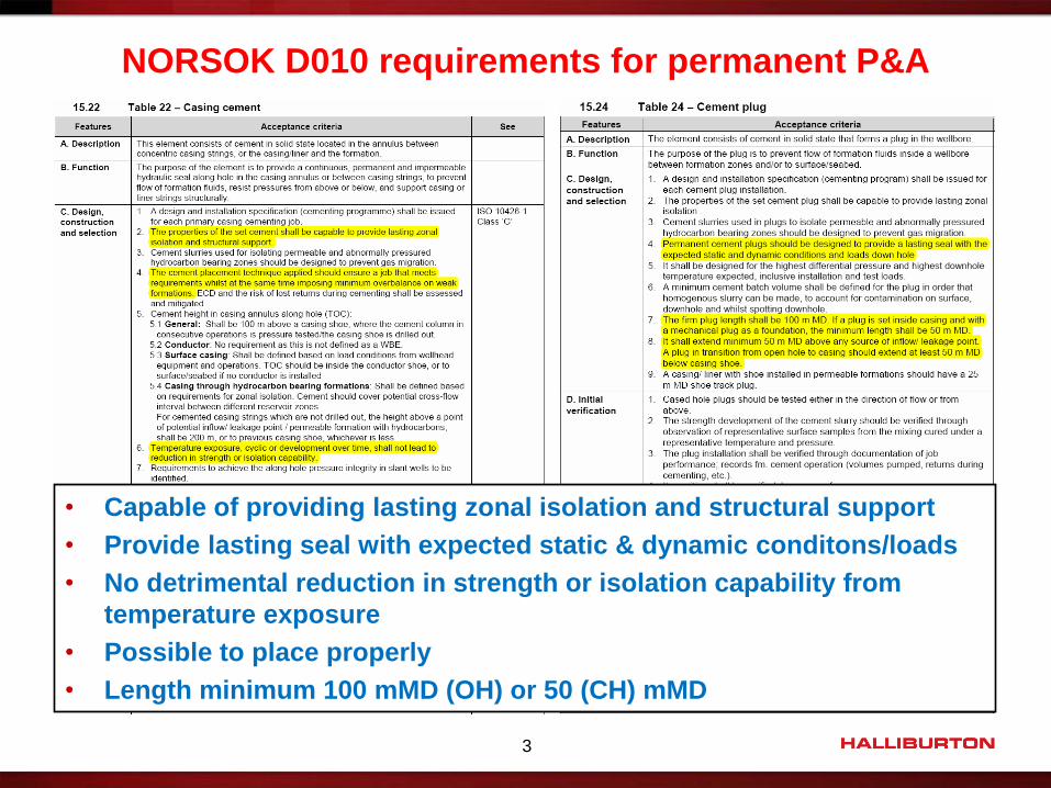
• Capable of providing lasting zonal isolation and structural support
• Provide lasting seal with expected static & dynamic conditons/loads
• No detrimental reduction in strength or isolation capability from
temperature exposure
• Possible to place properly
• Length minimum 100 mMD (OH) or 50 (CH) mMD
NORSOK D010 requirements for permanent P&A
4
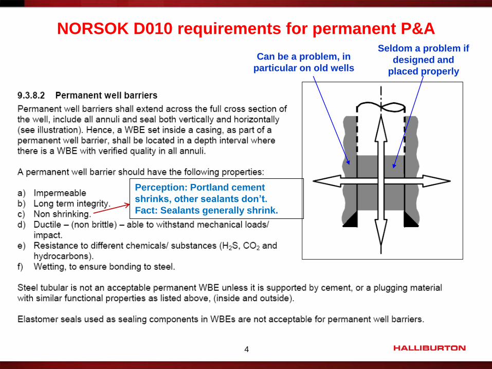
NORSOK D010 requirements for permanent P&A Seldom a problem if
designed and
placed properly
Can be a problem, in
particular on old wells
Perception: Portland cement
shrinks, other sealants don’t.
Fact: Sealants generally shrink.

5
Perception – Portland cement shrinks, other sealants don’t
Well, here are some facts: Most materials going liquid solid will shrink during solidification / chemical reaction
• Metals, glues, paints, plaster, resins, silicones, fly ash, etc. Water
Do not rely on bench-top demos or irrelevant test conditions
Examples below tested at relevant conditions, unconfined, no water feed, no mercy!
Undiluted Portland cement: 4 %, optimized Portland cement: 2 %, maybe less
Non-Portland alternative A: 7,5%
Undiluted Polyester based resin: 9,4% (with filler 5,2%)
Undiluted Epoxy based resin: 4% (with filler 2,5%)
PlastiSeal: <0,1%
Unconfined ΔV tests!

© 2011 HALLIBURTON. ALL RIGHTS RESERVED. 6
We know that Portland cement has hydration shrinkage • Reaction products are denser than starting components shrinkage
• Proportional to degree of hydration and water feed during hydration
• Bulk (effective external) shrinkage is ±4% (pure) if no external water feed
• Reduced to 1 – 1,5 % with effective external water feed during hydration
• These are unconfined ΔV test results
• In reality the external radial shrinkage is low
• Due to strong bond to pipe? Also seen when container is plastic material
• In reality the external radial shrinkage is more likely to be 0,1 – 0,5 %
Norway HPHT shrinkage/Expansion Test - Lab Ref NO-7162-3
No Water Access 7000 psi, 50 deg C
-5,00 %
-4,00 %
-3,00 %
-2,00 %
-1,00 %
0,00 %
0 20 40 60 80 100 120 140 160 180
Time [hrs]
Sh
rin
k [
%]
0,00
50,00
100,00
150,00
200,00
250,00
300,00
350,00
400,00
450,00
500,00
550,00
Co
mp
res
siv
e S
tre
ng
th / P
res
su
re [
ba
r]
Bulk Shrinkage Temperature Pressure Compressive Strength
Is the shrinkage a problem for abandonment plugs?
Why do we know this? 1. Cased hole plugs generally are pressure tested
successfully with mud if properly placed
2. In some cases water pressure tests leak slightly
3. leak path if any must be tight (microns)
4. 4% of 8,5” is 8,6 mm ΔD impossible!
5. Lab specimens have to be pressed out with X MT

© 2011 HALLIBURTON. ALL RIGHTS RESERVED. 7
Improved test methods
• Getting closer to reality
Norway HPHT shrinkage/Expansion Test - Lab Ref NO-7162-3
No Water Access 7000 psi, 50 deg C
-5,00 %
-4,00 %
-3,00 %
-2,00 %
-1,00 %
0,00 %
0 20 40 60 80 100 120 140 160 180
Time [hrs]
Sh
rin
k [
%]
0,00
50,00
100,00
150,00
200,00
250,00
300,00
350,00
400,00
450,00
500,00
550,00
Co
mp
res
siv
e S
tre
ng
th / P
res
su
re [
ba
r]
Bulk Shrinkage Temperature Pressure Compressive Strength
Is the shrinkage a problem for abandonment plugs?
-4,0%
-3,5%
-3,0%
-2,5%
-2,0%
-1,5%
-1,0%
-0,5%
0,0%
0,5%
0 5 10 15 20 25 30 35 40 45 50
% V
olu
me
Ch
ange
Time (hours)
Advanced shrinkage test - no water access @5000 psi
%ΔV, Extension %ΔV, Strain %ΔV, Total
Volumetric
Multi-directional

© 2011 HALLIBURTON. ALL RIGHTS RESERVED. 8
Does that mean we are OK?
• No – HC in gas or liquid form can migrate through very tight slots
• Good mud pressure test no gas migration
We know there will be tensile stresses in cement-pipe interface Normally bonding is stronger than the tensile stress coming from shrinkage
Within reasonable shrinkage vs. Tensile Strength & Young’s Modulus the result will be
porosity rather than debonding
A proper barrier based on such a material is dependent on this disparity
We have seen that pressure tests have damaged the seal No gas migration pressure test gas migration
Is the shrinkage a problem for abandonment plugs?

So what can we do?
• Focus on displacement efficiency and water wetting maximize bonding
• If possible cure cement plugs with pressure on casing inflate pipe
• Eliminate pipe-cement interface tensile stress
• Post curing cement expansion
Interface tension compression
Eliminate potential for debonding
9
How do we prevent or mitigate debonding?
© 2012 HALLIBURTON. ALL RIGHTS RESERVED.

© 2011 HALLIBURTON. ALL RIGHTS RESERVED. 10
Evidence - Plug integrity test
• Tananger JVS 1000 test cell
• ExpandaCem HT 1,95 SG
• Phase 1: Cure in N2 worst case shrinkage, no expansion
• Phase 2: Flow test with H20 fuel an expansion
JVS-1000 now located at Halliburton fluids lab, Tananger
Pipe: ID =100mm, L = 210 cm
How do we prevent or mitigate debonding?

11
Plug integrity test phase 1 – cure in dry environment
How do we prevent or mitigate debonding?
0
100
200
300
400
500
600
700
800
900
1000
1100
1200
0
20
40
60
80
100
120
140
160
180
200
220
240
0,00 10,00 20,00 30,00 40,00 50,00 60,00 70,00 80,00
Pre
ssu
re [
psi
]
Tem
pe
ratu
re [
°C]
Time [hrs] NO-118435-1
ExpandaCem plug integrity test Step 1 - Curing 1200 psi N2 / 144°C- No water access
Slurry Temperature Oil Temperature Top Pressure Bot Pressure
Sudden communication between top & bottom pressure sensor --> debonding
Heat of Hydration
Bottom pressure decrease due to shrinkage of cement
Bleed off top pressure, bottom pressure follows --> communication between top & bottom sensor

12
Plug integrity test phase 2 – flow with water
How do we prevent or mitigate debonding?
0
100
200
300
400
500
600
700
800
900
1000
1100
1200
-5,00
-4,50
-4,00
-3,50
-3,00
-2,50
-2,00
-1,50
-1,00
-0,50
0,00
0,50
1,00
1,50
2,00
2,50
3,00
3,50
4,00
4,50
5,00
0 10 20 30 40 50 60 70 80 90 100 110 120 130 140 150 160 170 180 190 200 210 220 230 240 250 260 270 280
Pre
ssu
re/T
em
pe
ratu
re [
psi
/°C
]
Flo
w R
ate
[m
l/m
in]
Time [hrs]
ExpandaCem plug integrity test - water injection & expansion Step 2 - Water injection test 144°C, ΔP = 1000 psi (1200 psi inlet 10 cm off bottom, 200 psi on top)
Flow Rate (Injection) Flow Rate (Receive) Delta P cement Temperature Oil Temperature
Stable flow at 0,01 ml/min --> permeability
Flow out ≈ flow in --> end of expansive reaction
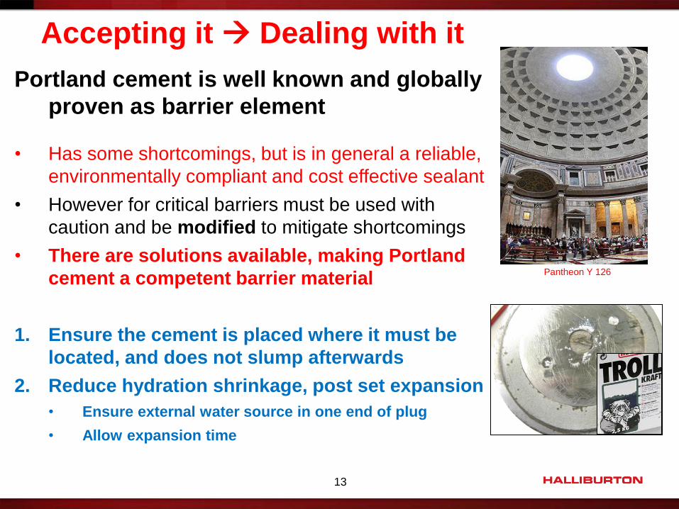
Portland cement is well known and globally
proven as barrier element
• Has some shortcomings, but is in general a reliable,
environmentally compliant and cost effective sealant
• However for critical barriers must be used with
caution and be modified to mitigate shortcomings
• There are solutions available, making Portland
cement a competent barrier material
1. Ensure the cement is placed where it must be
located, and does not slump afterwards
2. Reduce hydration shrinkage, post set expansion
• Ensure external water source in one end of plug
• Allow expansion time
13
Accepting it Dealing with it
Pantheon Y 126
14
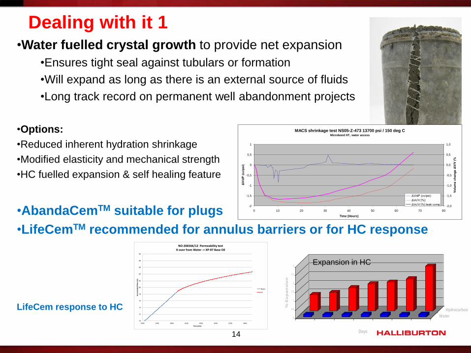
•Water fuelled crystal growth to provide net expansion
•Ensures tight seal against tubulars or formation
•Will expand as long as there is an external source of fluids
•Long track record on permanent well abandonment projects
•Options:
•Reduced inherent hydration shrinkage
•Modified elasticity and mechanical strength
•HC fuelled expansion & self healing feature
•AbandaCemTM suitable for plugs
•LifeCemTM recommended for annulus barriers or for HC response
LifeCem response to HC
MACS shrinkage test NS05-Z-473 13700 psi / 150 deg CMicrobond HT, water access
-2
-1,5
-1
-0,5
0
0,5
1
0 10 20 30 40 50 60 70 80
Time [Hours]
ΔV
/dP
(c
c/p
si)
-2,0
-1,5
-1,0
-0,5
0,0
0,5
1,0
Vo
lum
e c
ha
ng
e Δ
V/V
(%
)
ΔV/dP (cc/psi)
ΔVc/V [%]
ΔVc/V [%] leak comp
Dealing with it 1
0
0.5
1
1.5
2
2.5
3
% E
xp
an
sio
n
5 Day 9 Day 20 Day 41 Day 56 Day 79 Day 120 Day
Water
Hydrocarbon
Days
Expansion in HC
70
72
74
76
78
80
82
84
86
88
90
3500 3700 3900 4100 4300 4500 4700 4900
Acc
um
ula
ted
flo
w (
ml)
Time (min)
NO-206566/12 Permeability testX-over from Water -> XP-07 Base Oil
Water
oil

17
Modern materials and blends to mitigate shrinkage
•In the future we may see Portland based blends with minimal shrinkage
Dealing with it 2
0
50
100
150
200
250
300
350
400
450
500
550
600
-3,00 %-2,90 %-2,80 %-2,70 %-2,60 %-2,50 %-2,40 %-2,30 %-2,20 %-2,10 %-2,00 %-1,90 %-1,80 %-1,70 %-1,60 %-1,50 %-1,40 %-1,30 %-1,20 %-1,10 %-1,00 %-0,90 %-0,80 %-0,70 %-0,60 %-0,50 %-0,40 %-0,30 %-0,20 %-0,10 %0,00 %
0 50 100 150 200
Tem
pe
atu
re -
Pre
ssu
re [
°C -
bar
]
Vo
lum
e c
han
ge [
%]
Time [hrs]
Norway HPHT Shrinkage test - Abandacem L (12ppg)NO145221-11, 120°C @ 4800psi - water access, no expansion material
Cell dV % Specimen dV linear comp. (%) Measured end of test dV (%) Temperature Pressure

18
Deployment methods – phase 1 completed wells
Rig-less through-tubing bullhead to squeeze perforations as phase one
P&A is cost effective but requires volume control
Density of fluids creates a challenge on depleted wells
Free-fall causes loss of volume control
The solution:
AbandaCemTM Light
12 ppg / 1,50 SG
High strength
Low permeability
Low shrinkage
Post set expansion
Lightweight displacement fluid
5 – 7 ppg / 0,6 – 0,84 SG
Vacuum period reduced
Can be inflow-tested
Simulated Hydrostatics
144 154 164 174 184 194 204 214 224 234
Time
0
100
200
300
400
A
0
200
400
600
800
1000
1200
1400
1600
1800
2000
2200
BStage Vol (bbl) 13.0 ppg Cmt: Pressure (psi) 15.9 ppg Cmt: Pressure (psi)A B B
4321
1 2
3 4
15.9 ppg Cmt: Well on vacuum 13.0 ppg Cmt: Well on vacuum
Regain Pressure with 5.0 ppg Disp. Fluid and 13.0 ppg Cmt Regain Pressure with SW and 15.9 ppg Cmt
OptiCem v6.4.1028-Mar-11 15:21

19
P&A methods – phase 2 insufficient annular barrier fix
Traditionally handled with section milling or casing pulling
Time savings, cost, swarf are main drivers
2011 solution:
PWC & Halliburton perforation combo system (one trip)
Strong support from CoPNo
System engineered approach
Significant learning’s
Current experience:
Savings: 210 rig days and 148 tons swarf
3 plugs installed in one well in 9.4 days
Installed on fixed platforms and semi-submersible rigs
Increasing job count and customer base
Very successful
2012 further enhancements:
Great learning’s, improved procedures
Tailored TCP
Tailored AbandaCem & AbandaSpacer solutions
More features

20
P&A methods – WOC time during OH P&A operations
Challenge:
• WOC necessary to meet requirement for cement plug verification after OH P&A
• Physical tag
• Pressure test / inflow test
• WOC function of cement fluid time
• Can be quite long due to long operation time
• WOC = 3 x TT quite common
• Uncertainty of temperature
• Several plugs often required
• Multiple plugging operations
Solutions:
• Multiple plug & long fluid time can be addressed with BHKA-D system
• Long global success history (>300 jobs), SPE 102534
• WOC time uncertainty to some extent addressed with offshore UCA
• Reduced WOC vs fluid time designs to certain extent available
• Physical verification solution being developed
• Pending IP, substantial WOC time saving expected

21
Advanced logging solutions for barrier verification
Challenge: Verify adequate barrier in annulus with logging methods
• Existing cement job
• After Perforate-Wash-Cement operation
• Possibly poorly or non-centralized pipe
• Perforated pipe
• Spacer and cement possibly mixed together higher AI on homogeneous fluid
• Possibly spots of fluid embedded in the cemented interval
• Uncertain about annulus content above cement uncertain reference AI
Solutions:
• Determine quality of cement sheath using:
• Traditional CBL tool (including Radial tool) and Ultrasonic tool
• Cement to pipe bond
• Cement to formation bond
• Advanced Cement Evaluation (ACE) analysis method
• Statistical Variance Processing
• Differentiate cement from fluid Differentiate spots from homogeneous mixture
Norway support contact: Peyton Lowrey
© 2012 HALLIBURTON. ALL RIGHTS RESERVED. 23
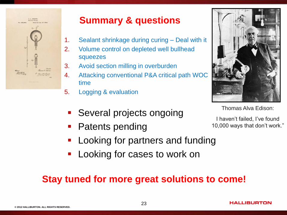
Several projects ongoing
Patents pending
Looking for partners and funding
Looking for cases to work on
Summary & questions
Thomas Alva Edison:
I haven’t failed, I’ve found
10,000 ways that don’t work.”
1. Sealant shrinkage during curing – Deal with it
2. Volume control on depleted well bullhead
squeezes
3. Avoid section milling in overburden
4. Attacking conventional P&A critical path WOC
time
5. Logging & evaluation
Stay tuned for more great solutions to come!