
CELLULARCOMMUNICATION AND ANTENNAS -...
50
Transcript of CELLULARCOMMUNICATION AND ANTENNAS -...

CONTENT
1 ‐ ABOUT ENGİTEK
2 ‐ CELLULAR COMMUNICATION
3‐ BASE STATION ANTENNAS
5 ‐ SMART , MIMO /massive MIMO ANTENNAS
2
4 ‐ 5G CELLULAR COMMUNICATION
6 ‐ DISCUSSIONS

1 ‐ ABOUT ENGİTEK LTD.

ABOUT ENGİTEK LTD.• Established in 2009• 5 engineers, 2 Technicians, 500m2 area, at OSTIM Industrial Zone.• Base stations antennas, mobile communications
4

ABOUT ENGİTEK LTD.• Sample Products ‐2G antenna – GSM900
5
890‐960MHz

ABOUT ENGİTEK LTD.• Sample Products – GSM1800 + 3G antenna
6
(1710‐1880)+(1910‐2170)MHz

ABOUT ENGİTEK LTD.• Sample Products – LTE‐800+GSM900+GSM1800+3G+4G/LTE‐2500 antenna
7
(790‐860) +(890‐960)+(1710‐1880)+(1910‐2170)+(2490‐2690) MHz
2 ‐ CELLULAR COMMUNICATION

9
CELLULAR COMMUNICATION• Evolution of Cellular Systems• 1G/2G/3G/4G/LTE ( f < 6GHz)• 5G (f > 6 GHz)
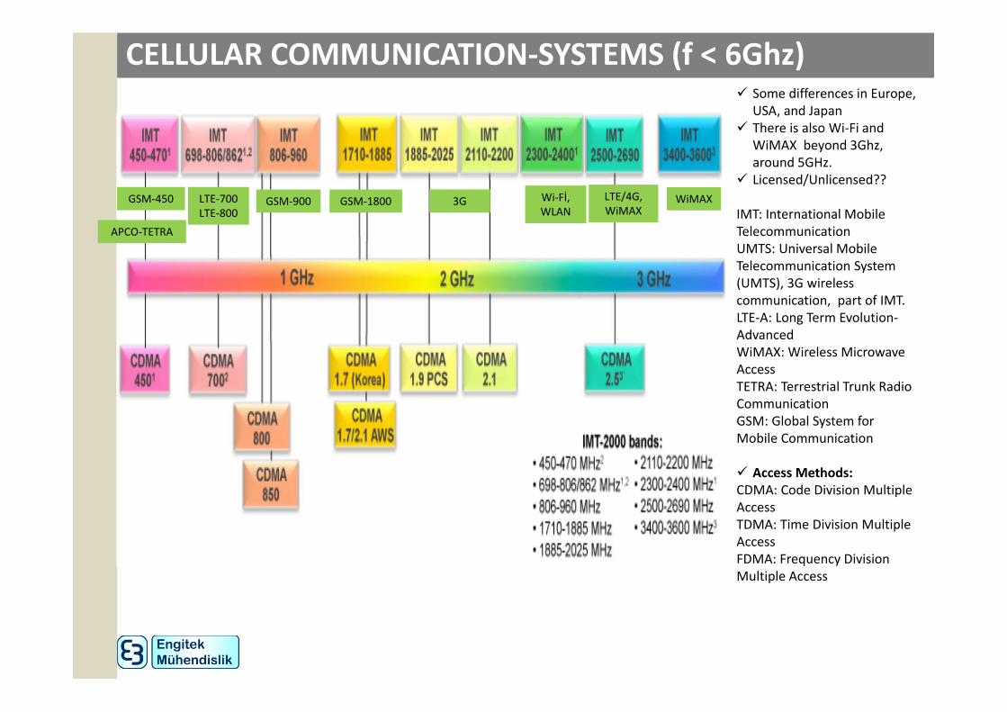
CELLULAR COMMUNICATION‐SYSTEMS (f < 6Ghz) Some differences in Europe,
USA, and Japan There is also Wi‐Fi and
WiMAX beyond 3Ghz, around 5GHz.
Licensed/Unlicensed??
IMT: International Mobile TelecommunicationUMTS: Universal Mobile Telecommunication System (UMTS), 3G wireless communication, part of IMT.LTE‐A: Long Term Evolution‐AdvancedWiMAX: Wireless Microwave AccessTETRA: Terrestrial Trunk Radio CommunicationGSM: Global System for Mobile Communication
Access Methods:CDMA: Code Division Multiple AccessTDMA: Time Division Multiple AccessFDMA: Frequency Division Multiple Access
GSM‐450
APCO‐TETRA
LTE‐700LTE‐800
GSM‐900 GSM‐1800 3G Wi‐Fİ,WLAN
LTE/4G,WiMAX
WiMAX
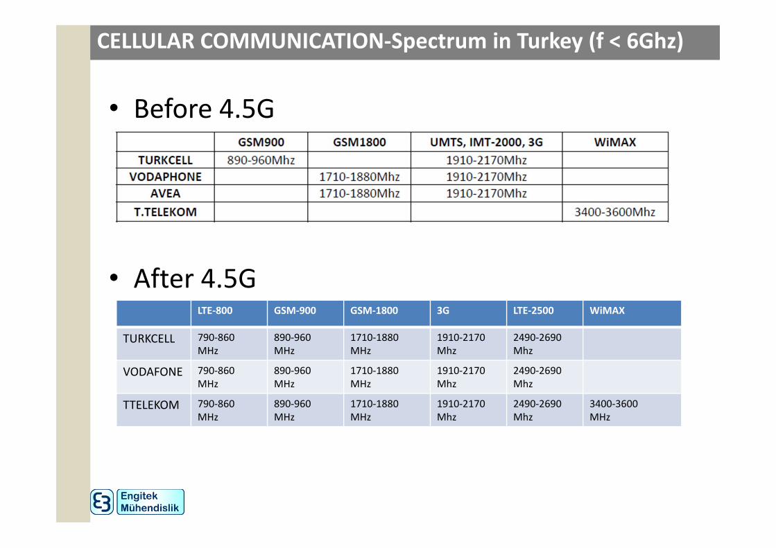
CELLULAR COMMUNICATION‐Spectrum in Turkey (f < 6Ghz)
• Before 4.5G
• After 4.5G LTE‐800 GSM‐900 GSM‐1800 3G LTE‐2500 WiMAX
TURKCELL 790‐860MHz
890‐960MHz
1710‐1880MHz
1910‐2170Mhz
2490‐2690Mhz
VODAFONE 790‐860MHz
890‐960MHz
1710‐1880MHz
1910‐2170Mhz
2490‐2690Mhz
TTELEKOM 790‐860MHz
890‐960MHz
1710‐1880MHz
1910‐2170Mhz
2490‐2690Mhz
3400‐3600MHz

CELLULAR COMMUNICATION
12
• BTS: Base Transceiver System (eNodeB)
• Each BTS has typically 3 sectors (alpha, beta, gamma).
• Other nearby BTS may cause co‐channel (same frequency) interference limiting capacity and quality of service.
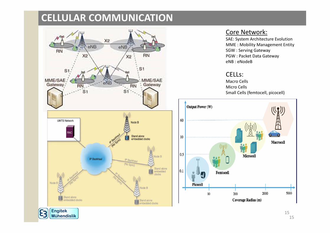
• CELLs:Macro CellsMicro CellsSmall Cells (femtocell, picocell)• Coverage Plan• Frequency Plan• Network Optimisations

CELLULAR COMMUNICATION
13
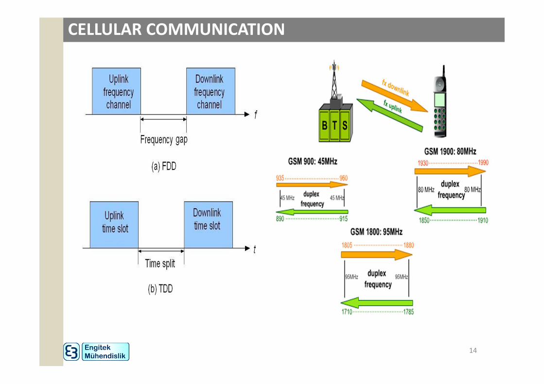
CELLULAR COMMUNICATION
14
CELLULAR COMMUNICATION
15
Core Network:SAE: System Architecture EvolutionMME : Mobility Management EntitySGW : Serving GatewayPGW : Packet Data GatewayeNB : eNodeB
CELLs:Macro CellsMicro CellsSmall Cells (femtocell, picocell)
15

3 ‐ BASE STATION ANTENNAS

BASE STATION ANTENNAS
1717
BASE STATION ANTENNAS
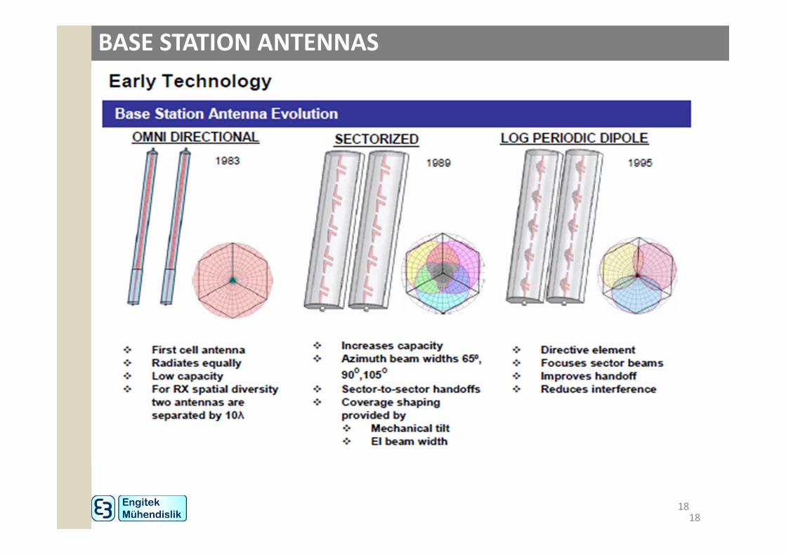
1818

BASE STATION ANTENNAS
1919

BASE STATION ANTENNAS
2020
BASE STATION ANTENNAS
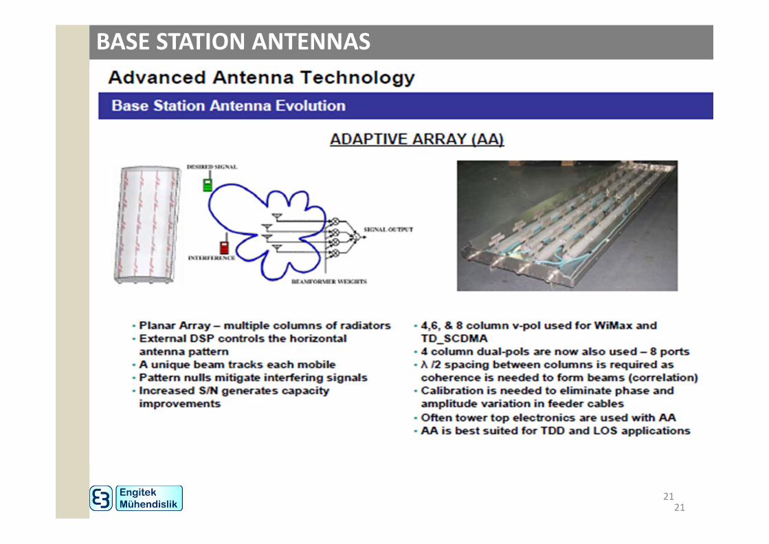
2121

BASE STATION ANTENNAS
2222
BASE STATION ANTENNAS
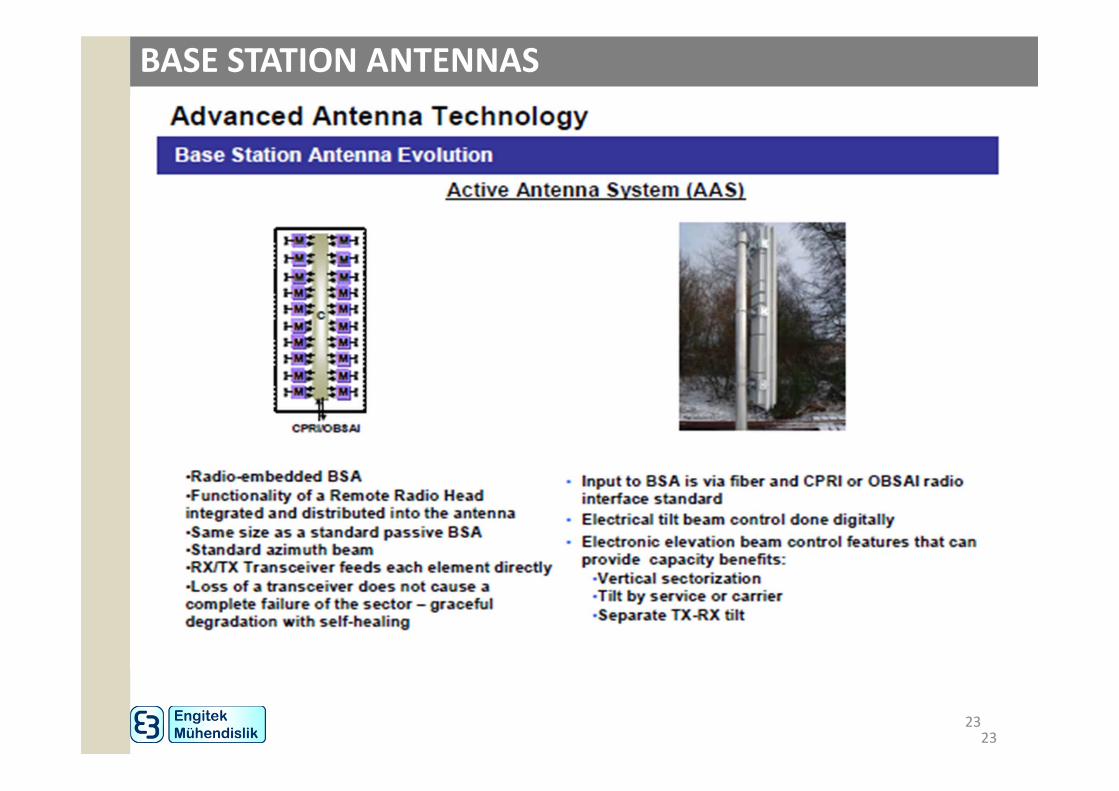
2323

BASE STATION ANTENNAS
2424

4 ‐ 5G CELLULAR COMMUNICATION
26
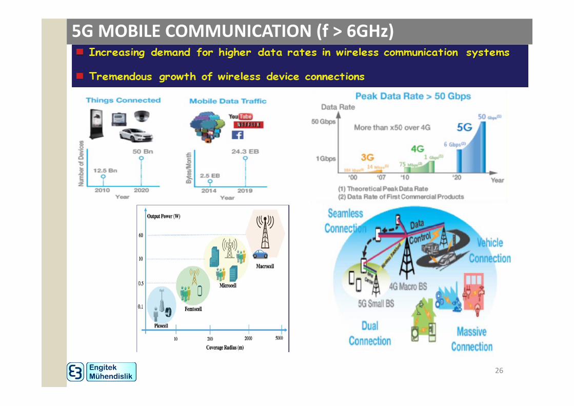
5G MOBILE COMMUNICATION (f > 6GHz)

27
5G MOBILE COMMUNICATION (f > 6GHz)• Objectives of 5G

28
5G MOBILE COMMUNICATION (f > 6GHz)• 10 Key Enabling Technologies for 5G

5G MOBILE COMMUNICATION
29
• We need new Spectrum for 5G

30
5G MOBILE COMMUNICATION (f > 6GHz)

5 – SMART, MIMO and MASSIVE MIMO ANTENNAS

WIRELESS ENVIRONMENT
32
S: Desired Signal (Watt)
N: Noise (Watt)
CCI: Interference (Watt)ISI: intersymbol interference.
Power
Bandwith (spectrum)
C: Capacity (Bits/Hz/Sec)
Coverage, Data Rate, # of users in the cell
Data/Service Quality (QoS)
SNR: Signal to Noise Ratio
SINR: Signal to Interference and Noise Ratio
Pe : Probability of Error
BER: Bit Error Rate
# of drop calls
……….

DATA TRAFFIC AND SPECTRUM
33

34

• The extraordinary growth in wireless data traffic is putting immense strain on the operator’s network. To address this demand and increase capacity, operators have 5primary tools at their disposal:
1. Adding Cell Sites is an effective but expensive approach to adding capacity. In general adding new real estate is time consuming and increasingly prohibitive. With median inter-site distances dropping from 5km to 2km and recently to less than 200m in dense urban areas, the operator has less choice in selecting affordable property. Doubling the number of cell sites approximately doubles the network capacity and the throughput per user (assuming the user density stays constant), and greatly improves the peak user and the aggregate throughput per km2.
2. Adding sectors, such as changing from 3 sectors to 6 sectors, is a useful way to approximate the introduction of new cells. However, this does not quite double the capacity as the “petals” of 6 sector coverage do not interleave as well as 3 sector coverage, and the fractional overlap of 6 sectors is greater. This also challenges handoff processing when near highways. This is a common approach in dense urban areas where rooftops are available. There is about a 70% increase in capacity in moving from 3 to 6 sectors in an environment with low angle spread (where the base station is located above the clutter).
SOLUTIONS TO CAPACITY

3. Adding Carriers (or more accurately, bandwidth) directly adds to capacity.The LTE standard is particularly adept at utilizing increased bandwidth. In addition, in the USA, the FCC permits increasing radiated power with the bandwidth in the lower 700 MHz bands providing improved penetration and coverage. Doubling bandwidth at least doubles throughput.
4. Improved air interface capabilities, It has been observed that, with improvements in air interface (while leaving everything else the same such as bandwidth and antenna configuration) we are seeing diminishing returns on improvements. It is clear that something more than simply increasing modulation and coding rates is needed.
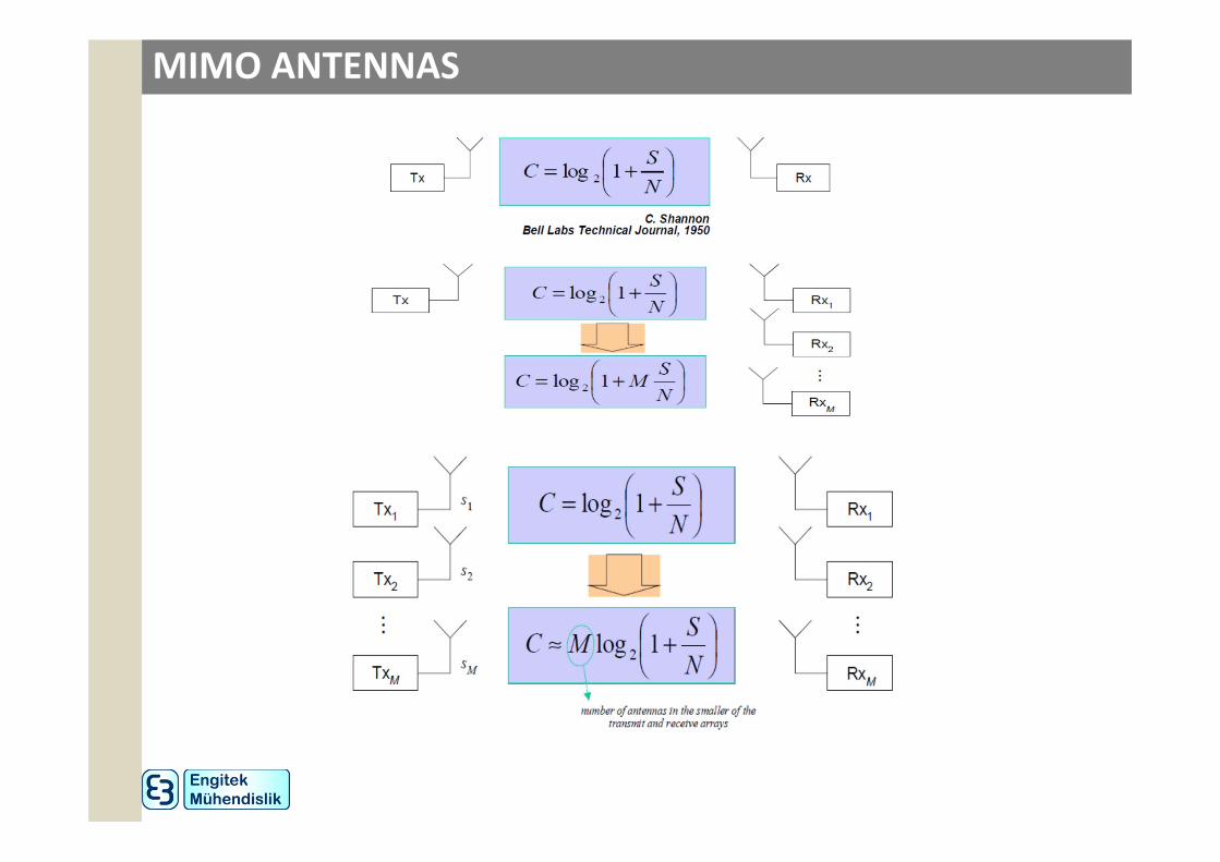
5. Smart antennas provide the next substantial increase in throughput. The peak data rates tend to be proportional to the number of send and receive antennas, so 4x4 MIMO is capable of serving twice the peak data rates as 2x2 MIMO systems.
• SMART ANTENNAS
• MIMO ANTENNAS
• MASSIVE MIMO ANTENNAS
SOLUTIONS TO CAPACITY

SMART ANTENNAS

SMART ANTENNAS
• A smart antenna system combines an antenna array with digital signal-processing capability to transmit and receive in a predefined or adaptive, spatially sensitive manner. This enables such a system to change the directionality of its radiation patterns in response to the particular signal environment. This results in dramatically increased performance characteristics of a wireless system.
Switched Beam—a finite number of fixed, predefined patterns or combining strategies (sectors). comprises only a basic switching function between separate directive antennas or predefined beams of an array
Adaptive Array—an infinite number of patterns (scenario-based) that areadjusted in real time. continuous tracking can be achieved by including adirection of arrival (DoA) algorithm for the signal received from the user canbe viewed as a generalization of the switched lobe concept

SMART ANTENNAS
Antenna Array
Active Beam
Switched Beam System
Antenna Array
Desired User
Interfering User
Adaptive Array

SMART ANTENNAS
Desired Signals
Co-channel Interfering Signals
Interference Rejection Comparison

SMART ANTENNAS
Coverage Patterns for Switched Beam and Adaptive Array Antennas

SMART ANTENNAS

MIMO ANTENNASMultiple antenna systems (Multiple Input, Multiple Output – MIMO) gives a significant enhancement to data rate and channel capacity.
MIMO ANTENNAS

MIMO ANTENNAS

SMART+MIMO ANTENNAS

BENEFITS OF SMART AND MIMO ANTENNAS

MASSIVE MIMO
• Massive MIMO is the subject of 5G
• At 5G frequencies, wavelength gets smaller ( 1cm at 30Ghz, 0.5cm at 60Ghz)
• So it becomes possible to make array antennas with big numbers of elements such as 64x64 and 128x128.
• Massive MIMO brings many further advantages of MIMO technology in 5G.
6 ‐ DISCUSSIONS

• Antenna Engineering (hardware)
• RF/Microwave Engineering (hardware)
• Telecommunication Engineering (DSP, embedded software, SDR)
• Software Engineering (Networks, SDN)