![Development and Design of Binder Systems for Titanium ... · include, for example, dental and biomedical implants, aerospace components, medical and surgical tools, and chemical devices.[8]](https://static.fdocuments.net/doc/165x107/5fff0c282e52ab23407db1a7/development-and-design-of-binder-systems-for-titanium-include-for-example.jpg)
Cell-surface interaction in biomedical implants assessed ... · Cell-surface interaction in...
8
Cell-surface interaction in biomedical implants assessed by simultaneous fluorescence and reflection confocal microscopy J Vilches *1 , JI Vilches-Perez 2 and M. Salido 1, 1 Department of Histology. School of Medicine. University of Cadiz. Edificio Servicios Generales. c/ Dr Marañon 3, 11002 Cadiz, Spain. 2 Department of Oral Surgery. School of Dentistry. University of Seville. c/ Avicena s/n. 41005. Seville. Spain. At present it’s accepted that much of the dynamic function of cells is regulated from outside by signals from extracellular environment. The surrounding microenvironment provides a construct in which cells move, grow, organize and differentiate to form tissues. Cell-material interactions are one of the main goals in tissue engineering. In biomedical implants, mechanical forces transduced through the microenvironment alter the morphology and genetic expression (i.e. cytoskeleton) in the cells. Confocal microscopy is an important advance in microscopy and has enabled the imaging of intact, optically nontransparent specimens to produce high resolution images of cells and tissues with the use of fluorescent probes. Combined with reflectance mode is useful to provide detailed images of cell-surface interactions in biomedical devices. In this chapter we examinate the application of CLSM to directly visualize and quantify, at the cellular level, the interactions with biomaterial surfaces, with the aim of tailoring surfaces that provide chemical and physical cues to guide differentiation and assembly of cells to form tissue and to become biocompatible to the surrounding tissue. Keywords: confocal microscopy; osteoblasts; cytoskeleton; dental implants; titanium;microtopography. 1. Introduction Understanding how the cellular response proceeds within the three dimensional context of structural and mechanical support offered by the extracellular matrix will drive the development of scaffolds and devices to be used for repairment and replacement of defective tissues. The ability of an engineered biomaterial to approximate the structural and mechanical aspects of the cellular microenvironment is an important factor in determining the eventual success or failure of such engineered devices when used clinically for tissue repair or replacement. In this sense, an approach to the detailed mechanisms involved in the transmission of mechanical forces between the cell and its supporting extracellular scaffold, i.e. mechanotransduction, that influence cell morphology and cytoskeletal organization, phenotype and function are of paramount importance as cell-material interactions are one of the key components in tissue engineering [1-3]. The ability to probe such interactions is tremendously valuable to all researchers seeking to design improved biomaterials with enhanced functionality and specificity. Confocal laser scanning microscope (CLSM) appears to be a valuable and non invasive tool for simultaneous 3D visualization of both cell morphology and structure, i.e. cytoskeletal organization, and material scaffolds [2-4]. The principle of confocal microscopy is that the out of focus light is removed from the image by the use of a suitable positioned “pinhole”. This not only creates images of exceptional resolution, but also allows one to collect optical slices of intact, optically non transparent specimens with the use of fluorescent probes, and to use these slices to create a 3D representation of the sample. The CLSM is also capable of creating excellent images using backscattered or reflected light. Confocal backscatter imaging is particularly useful for creating 3D images of the surface of materials. In addition to image data of cell morphology, microstructural data of scaffolds and cell-scaffold interaction * Corresponding author: e-mail: [email protected], Phone: +34 956015832 ©FORMATEX 2007 Modern Research and Educational Topics in Microscopy. A. Méndez-Vilas and J. Díaz (Eds.) _______________________________________________________________________________________________ 60
Transcript of Cell-surface interaction in biomedical implants assessed ... · Cell-surface interaction in...
Cell-surface interaction in biomedical implants assessed by simultaneous fluorescence and reflection confocal microscopy
J Vilches*1, JI Vilches-Perez2 and M. Salido1, 1Department of Histology. School of Medicine. University of Cadiz. Edificio Servicios Generales. c/ Dr Marañon 3, 11002 Cadiz, Spain. 2Department of Oral Surgery. School of Dentistry. University of Seville. c/ Avicena s/n. 41005. Seville.
Spain. At present it’s accepted that much of the dynamic function of cells is regulated from outside by signals from extracellular environment. The surrounding microenvironment provides a construct in which cells move, grow, organize and differentiate to form tissues. Cell-material interactions are one of the main goals in tissue engineering. In biomedical implants, mechanical forces transduced through the microenvironment alter the morphology and genetic expression (i.e. cytoskeleton) in the cells. Confocal microscopy is an important advance in microscopy and has enabled the imaging of intact, optically nontransparent specimens to produce high resolution images of cells and tissues with the use of fluorescent probes. Combined with reflectance mode is useful to provide detailed images of cell-surface interactions in biomedical devices. In this chapter we examinate the application of CLSM to directly visualize and quantify, at the cellular level, the interactions with biomaterial surfaces, with the aim of tailoring surfaces that provide chemical and physical cues to guide differentiation and assembly of cells to form tissue and to become biocompatible to the surrounding tissue.
Keywords: confocal microscopy; osteoblasts; cytoskeleton; dental implants; titanium;microtopography.
1. Introduction
Understanding how the cellular response proceeds within the three dimensional context of structural and mechanical support offered by the extracellular matrix will drive the development of scaffolds and devices to be used for repairment and replacement of defective tissues. The ability of an engineered biomaterial to approximate the structural and mechanical aspects of the cellular microenvironment is an important factor in determining the eventual success or failure of such engineered devices when used clinically for tissue repair or replacement. In this sense, an approach to the detailed mechanisms involved in the transmission of mechanical forces between the cell and its supporting extracellular scaffold, i.e. mechanotransduction, that influence cell morphology and cytoskeletal organization, phenotype and function are of paramount importance as cell-material interactions are one of the key components in tissue engineering [1-3]. The ability to probe such interactions is tremendously valuable to all researchers seeking to design improved biomaterials with enhanced functionality and specificity. Confocal laser scanning microscope (CLSM) appears to be a valuable and non invasive tool for simultaneous 3D visualization of both cell morphology and structure, i.e. cytoskeletal organization, and material scaffolds [2-4]. The principle of confocal microscopy is that the out of focus light is removed from the image by the use of a suitable positioned “pinhole”. This not only creates images of exceptional resolution, but also allows one to collect optical slices of intact, optically non transparent specimens with the use of fluorescent probes, and to use these slices to create a 3D representation of the sample. The CLSM is also capable of creating excellent images using backscattered or reflected light. Confocal backscatter imaging is particularly useful for creating 3D images of the surface of materials. In addition to image data of cell morphology, microstructural data of scaffolds and cell-scaffold interaction
* Corresponding author: e-mail: [email protected], Phone: +34 956015832
©FORMATEX 2007Modern Research and Educational Topics in Microscopy. A. Méndez-Vilas and J. Díaz (Eds.) _______________________________________________________________________________________________
60

can be readily obtained using this method. The reliance of scattering signals from the scaffolds obviates the need to fluorescent label all structures (biological and non biological) for visualization [3]. Surface topography of scaffolds and, in particular, roughness and form, play an important role in determining the functional performance of engineering parts. Measurement of surface topography not only falls within the field of quality control and product optimization [5, 6]. To maintain proper functionality, cells rely on adhesions to and interactions with the surrounding substrate, structure or extracellular matrix. The surrounding microenvironment provides a construct in which cells move, orient, organize and differentiate to form cultures and tissues [3]. Precise definition of three dimensional microstructural information will allow the development of mechanical models that predict states of stress and strains based on cell-scaffold biomechanics [1]. Engineered tissues are composed of cells, extracellular matrices and scaffolds. In our study, NHOst cells (Cambrex, Walkersville, MD, USA) seeded on TiCP Osseotite® or TiCP machined disks were used as an engineered tissue model. For actin cytoskeletal organization assessment, cells were immunolabelled with rhodamine-phalloidin, after 12, 24, 48 hours of culture. We herein describe our experience in specimen preparation and technical cues for optimal image acquisition and quantification with the combined use of backscattered and fluorescence modes in CLSM for the assessment of cell-surface interactions and cytoskeletal organization of human normal osteoblastic NHOst cells grown in vitro on titanium scaffolds with different surface topography.
2. Scaffolds
2.1 Titanium surfaces and osteoblasts
Titanium and titanium alloys have been widely used over the past 20 years as biomedical materials in orthopaedic and dental surgeries due to their high mechanical and corrosion resistance, as well as their biocompatible properties. The implant surface can influence biological osteoconduction and bone formation remodelling and during the sequence of these events, surface roughness seems to play a key role [7, 8]. In the last years, different surface treatments have been developed in order to achieve an increase of surface roughness on titanium dental implants, such as Osseotite ®, that may promote cellular adhesion, increased cell differentiation as well as improved osteoblast expression for a better osseointegration and more bone formation.
2.2 Scaffolds preparation
Prefabricated 2 cm x 1.5 mm disks were kindly provided by 3i (Palm Beach Gardens, USA). Ti- CP machined, and the dual thermo-acid etching Ti -CP- Osseotite ® disks were used for the experiments. Before use, the disks were immersed in 100% ethanol for 10 min, air dried, and exposed under u.v. light for 30 min on each side, and finally rinsed in endotoxin free phosphate buffered solution (Ku et al., 2002), and deposited on small sterile Petri dishes prior to cell seeding. Tissue culture Willco ® (Leica Microsystems, Darmstaad, Germany) plates with 0.17 mm glass bottom were used as the control surface. For the adequate examination of disks in the confocal microscope, one holed polycarbonate slides were designed in our laboratory and fabricated by means of control precision systems. (Mecaprec, Cadiz, Spain) The device designed allows us to carefully preserve cellular integrity and also avoids the problem of device thickness interference with focus distance, as the disk is inserted into the slide prior to mounting with appropriate mounting media and a 0.17 mm coverslip. For the combined study of cells growing on materials of variable thickness, the difference in working distance can be a problem that is avoided with the device designed.
Modern Research and Educational Topics in Microscopy. A. Méndez-Vilas and J. Díaz (Eds.) ©FORMATEX 2007 _______________________________________________________________________________________________
61

3. Cell culture
Norman human osteoblastic NHOst ® cells (Cambrex, Walkersville, MD, USA) were seeded at a density of 5000 cells/ cm2 and incubated in Osteoblast Growing Medium, OGM, (Cambrex,Walkersville, MD, USA) containing 10% foetal bovine serum (Cambrex, Walkersville, MD, USA), 1% gentamycin sulphate/amphotericin B (Cambrex, Walkersville, MD, USA) and 1% ascorbic acid (Cambrex, Walkersville, MD, USA), as recommended by suppliers, at 37º and 5% CO2 until the experiments were started. Growth medium was changed every day after seeding. Before the cells became 80% confluent they were subcultured with 2ml of 0.25 mg/ml trypsin EDTA warmed to 37º (Cambrex, Walkersville, MD, USA) after rinsing with 5ml Hepes-BSS (Cambrex, Walkersville, MD, USA) at room temperature. Once cells were detached, trypsin EDTA was neutralized by adding 4 ml of trypsin neutralizing solution (Cambrex, Walkersville, MD, USA). Harvested cells were seeded on the different disks at a density of 5000 cells/ cm2 and immunostained after 12, 24 and 48 h. Growth medium was changed every day until the experiment was finished. NHOst cells are assured for experimental use for ten population doublings, which were not exceeded during the assay.
4. Immunohistochemistry of actin cytoskeleton
At the end of the specific culture time, cells were washed twice with prewarmed phosphate –buffered saline, (PBS), pH 7.4, and fixed with 3.7% paraformaldehyde (PFA) solution in PBS for 10 min. at room temperature and washed twice with prewarmed PBS. The cells were then permeabilized with 0.1 % Triton x-100 (Sigma,St Louis, Missouri, USA) for 5 min and washed twice with prewarmed PBS. To reduce non-specific background staining 1% bovine serum albumin (BSA) in PBS was added to the surfaces for 20 min and immunostained for 20 min. with rhodamine phalloidin, 12.5µl of methanolic stock solution (Sigma,St Louis, Missouri, USA) in 500 µl PBS for each sample. Staining solution was discarded and disks were then rinsed with prewarmed PBS three times prior to mounting with vectashield ® (Vector Labs. Burlingame CA, USA) and 0.17 mm coverslips, in one holed polycarbonate slides designed in our laboratory and fabricated by means of control precision systems (Mecaprec, Cadiz, Spain).
5. Confocal examination
5.1 General remarks
The cells and disks were simultaneously visualized using an spectral inverted Leica TCS-SL confocal microscope equipped with a 63.0 x 1.30 glycerol objective, with adjustable collar for correcting for coverslip thickness, allowing simultaneous acquisition of rhodamine phalloidin staining of actin cytoskeleton (excitation 554 nm / emission 573nm) and surface reflectance. Four isolated disks were analyzed in each group for topographical information, and four disks with cells growing on them were analyzed for each group to assess surface influence on cytoskeletal organization and cell morphology. At least 50 cells per disk were analysed. Profilometric studies, for the quantification of maximal and minimal values in surface profile, distance between peaks in each surface, width of grooves and valleys, and axial ratio of the cells growing on the different surfaces were assessed. All samples were exposed to laser for a time interval not higher than 5 min to avoid photobleaching. The excitation beam splitter selected was a DD 488/543. The laser was set to the lowest power that was able to produce a fluorescent signal. Maximum voltage of photomultipliers was used to decrease the required laser power as much as possible, the lowest voltage being 279.3 V and the highest voltage 778.7 V. Offset was maintained at 0. A pinhole of 1 Airy unit was used. Images were acquired at a resolution of 512 x 512 or 1024 x 1024, with a mean voxel size of 209.20 nm. Single images or stacks of 3D images were collected and processed for the quantitative analysis using the imaging software provided by the Leica TCS SL system. Series were acquired in the xyz mode with a
©FORMATEX 2007Modern Research and Educational Topics in Microscopy. A. Méndez-Vilas and J. Díaz (Eds.) _______________________________________________________________________________________________
62

mean line average of 3 to reduce “noise” level in the image and compiled into either single-view overlay projections or a three dimensional projection. [9] Both reflected light and fluorescence were collected along the same optical axis and separated immediately prior to entry into respective photomultipliers (PMT) thus allowing discrimination of fluorescence from the scattered light signal.
5.2 Spectral detection system
The Leica TCS SL inverted microscope employed in the study uses spectral separation of various wavelengths of fluorescent light as a valuable alternative method to the most traditional one of using individual dichroic mirrors and optical filters. The microscope uses a prism to separate the light into its component colours, which are then directed to individual detection channels. Although this system highly increases the complexity in the use of the microscope, one of the most important advantages of spectral separation is the greatly increased versatility of the instrument in both defining spectral regions that are directed to individual channels and the ability to separate fluorophores with highly overlapping emission spectra. [10]
5.3 Backscattered light imaging
Reflected light confocal imaging is more properly known as backscattered light imaging to emphasize the point that the light been collected is that which is “scattered” by the sample, rather than the direct reflection from the sample. In fact, the direct reflection from the sample often seriously degrades the quality of the image. In this approach the primary dichroic mirror is replaced with a neutral beam splitter that transmits the laser light scattered by the specimen back to the detector. Typically the 488 nm laser line is used, but other lines work equally well. [10]
5.4 Selection of laser line
Full control of the intensity of the laser light that will reach the specimen is most important in confocal microscopy. Furthermore, laser intensity at the sample needs to be kept to a minimum to avoid unnecessary photobleaching of the sample. In our case, an argon laser line of 488 was used both for the backscattered light imaging of the titanium disks and for excitation of rhodamine-phaloidin, and laser power was set to a minimum not only to avoid photobleaching of immunolabelled actin filaments, but also to minimize the reflection from the titanium surfaces.
5.5 Pinhole
The confocal pinhole, where out-of-focus light is removed, is an essential component of a confocal microscope, allowing the microscope to create optical sections. This is the basis of the ability of the confocal microscope to image deep within the cell or tissue sample, and the key to the creation of 3D images of cells. Opening the pinhole greatly increases the sensitivity of the instrument, although at the expense of loss in z-resolution and loss in effective x-y resolution due to out-of-focus light detracting from the image [10]. A pinhole size of 1 Airy disk has been used in this study in order to optimize image acquisition both for surface topographical features obtained with the backscattered mode and for the assessment of cytoskeletal organization in response to the microstructural cues from the scaffold with the fluorescence mode.
5.6 Selection of objectives and working distance
No other component of the microscope is as instrumental in determining the information content of an image as the objective. While this is true for any conventional microscope, it is particularly true for
Modern Research and Educational Topics in Microscopy. A. Méndez-Vilas and J. Díaz (Eds.) ©FORMATEX 2007 _______________________________________________________________________________________________
63
confocal scanning, where the objective becomes the condenser as well and needs to combine a high degree of optical correction with good throughput and a minimum of internal stray light or photon noise generation [11]. The condition of the objective lens is critical for obtaining high quality images on the confocal microscope. Great care should be taken in cleaning the objectives, as a “dirty” front lens element will result in a poor quality image. The use of glycerol/water immersion objective, with adjustable collar for correcting for coverslip thickness, with a long working distance allowing the simultaneous detection of the fluorescence and the reflection channels. As described above, it has demonstrated to be a valuable tool for the assessment of the interaction between cells and scaffolds and the subsequent achievement of the most favourable conditions for the non-invasive analysis of osteoblasts-implants interface by CLSM, thus allowing us to obtain a 3D view of fluorescent labelled cell cytoskeleton at the cell implant interface. For reflected light objectives, the distance between the focus plane and the closest structural element of the objective is called the working distance (WD). In a confocal microscope, the WD sets an absolute limit that the focus plane can be below the top surface of the coverslip. This is particularly relevant for combination studies with fluorescence and backscattered images as the absorption properties of the scaffold (i.e. opacity) can have a negative impact on image contrast in the backscattered (BSL) mode. When the objective is focused into a cave in the irregular rough surface, the scattered and reflected rays from the structure of interest are modulated by the presence of irregularities between the objective and focal plane. Thus, the selection of an objective with the appropriate WD that allows us to combine excellent resolution for fluorescence mode together with reflectance mode becomes imperative.
5.7 Immersion media
The numerical aperture (NA) of a “dry” objective is limited to 0.95 due to total internal reflection of higher angle light rays. Obtaining higher resolution necessitates the use of a higher refractive index immersion media between the coverslip and the front lens of the objective, and an objective lens specifically designed for the immersion media used. The selected glycerol immersion provides a relatively high refractive index that allows the use of a 63.0 x 1.30 glycerol/water objective, of paramount importance for its WD and higher penetration.
5.8 Coverslip thickness
In light microscopy, the coverslip is an integral part of the optics of the microscope. The correct thickness of the coverslip is important for high resolution imaging and is critical when using a relatively high NA objective. Incorrect coverslip thickness is often a cause of somewhat out-of-focus images when using conventional light microscopy. However, in a confocal microscope the out-of-focus light is rejected by the confocal pinhole, and so the effect of coverslip thickness mismatches is a serious loss of signal. The spherical aberration induced by non-specified coverslip thickness leads to loss of energy at the pinhole, reduced depth discrimination, and an axial shift of the best focus [11]. Thus, the adequate correction for 0.17 mm thickness coverslips, achieved in this study by manipulation of the adjustable collar of the 63.0 x 1.30 glycerol objective is imperative [11]. For the visual control of adjustment, the flat surface of the coverslip should be imaged as a thin horizontal white line when scanning the sample in the xz mode.
5.9 Image acquisition. Zoom
High resolution imaging by confocal microscopy may necessitate adjusting the zoom factor to suit the resolving power of the microscope objective in order to satisfy the Nyquist criteria for correct sampling. The Nyquist sampling theorem states that, when a continuous image is digitised, the information content of the signal will be retained only if the diameter of the area represented by each pixel is, at least, 2.3 x smaller than the optical xy resolution limit of the microscope. The optimal zoom factor, thus, is
©FORMATEX 2007Modern Research and Educational Topics in Microscopy. A. Méndez-Vilas and J. Díaz (Eds.) _______________________________________________________________________________________________
64

dependent on both the NA and the magnification of the objective. In the present study zoom has been kept under 2.0, thus adjusting to axial resolution of the objective.
6. Confocal examination of surfaces
Ti CP Osseotite ® disks showed a marked increase in the surface roughness with prominent peaks and caves, some of them with well defined contours and some others forming a wide trabecular surface with randomly distributed peaks. The distance between peaks, consequently, was highly variable, with values ranging from 24.45 µm up to 183.67 µm. The mean diameter of the caves was found to be largely variable, ranging from 8.01 and 39.27 µm as shown in figure 1A. As revealed in the profilometric study, in figure 1B, this pattern notably increased the mean roughness of the surface that showed a minimum value of 1.9 µm in depth and a maximum peak value of 8.79 µm. Figure 1C shows that the machined surface revealed a regular planar surface, with parallel grooves caused by the waviness inherent to the machining operation. The profilometric measurement, in figure 1D, resulted in a minimum value of 1.2 µm for the depth of the valleys and a maximum value of 4.15 µm for the top of the embossed structure. The mean distance between tops reached 18.28 µm, the mean width for the valleys was 2.85 µm, the mean value for the groove on top of each embossed ring was 1.51 µm.
Fig. 1. Titanium disks imaged by CLSM reflectance mode.A: TiCP Osseotite,: surface roughness with prominent peaks and caves. Magnification 63 x 1.30, Zoom 2.00. B: Topographical image. C: TiCP machined disk, regular planar surface, with parallel grooves. Magnification 63 x 1.30, Zoom 1.88. D: Topographical image.
Modern Research and Educational Topics in Microscopy. A. Méndez-Vilas and J. Díaz (Eds.) ©FORMATEX 2007 _______________________________________________________________________________________________
65
7. Confocal examination of cell morphology
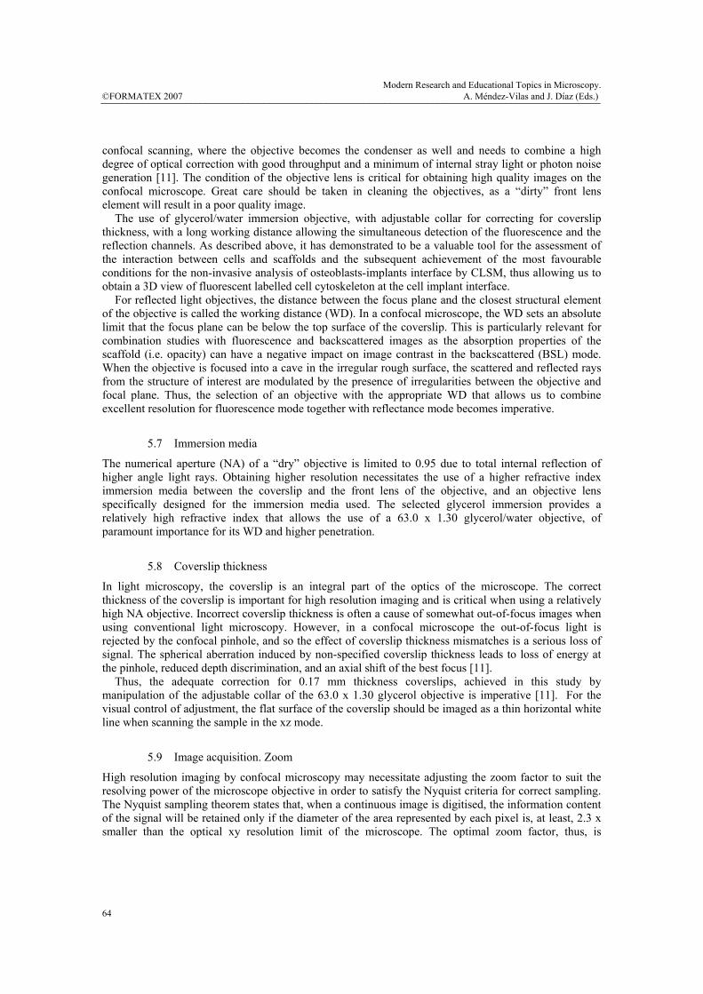
Figure 2 shows that in the TiCP Osseotite ® disks, where the distance between peaks increases, the cells presented an increasingly polarised spreading with emission of either wide lamellopodia or long filopodia, depending on the surface roughness and the distance between subjacent peaks, and showed the longest morphology, with a mean axial ratio that rose to 3.5. In the machined TiCP disks, as long as the peak to peak distance is less than the length of the cell body, the cells flattened and spread adopting a morphology largely radial, as shown in figure 2B with a mean axial ratio of 1.1, and anchored themselves to the surface through long dendritic filopodia both along the grooves of the surface or crossing over them in a perpendicular way.
Fig. 2. A: Fusiform cell with long filopodia grown on TiCP Osseotite disk. Magnification 63 x 1.30, Zoom 1.85. B: Radial cell with long dendritic filopodia grown on TiCP machined disk. Magnification 63 x 1.30, Zoom 1.25.
8. Cytoskeletal organization
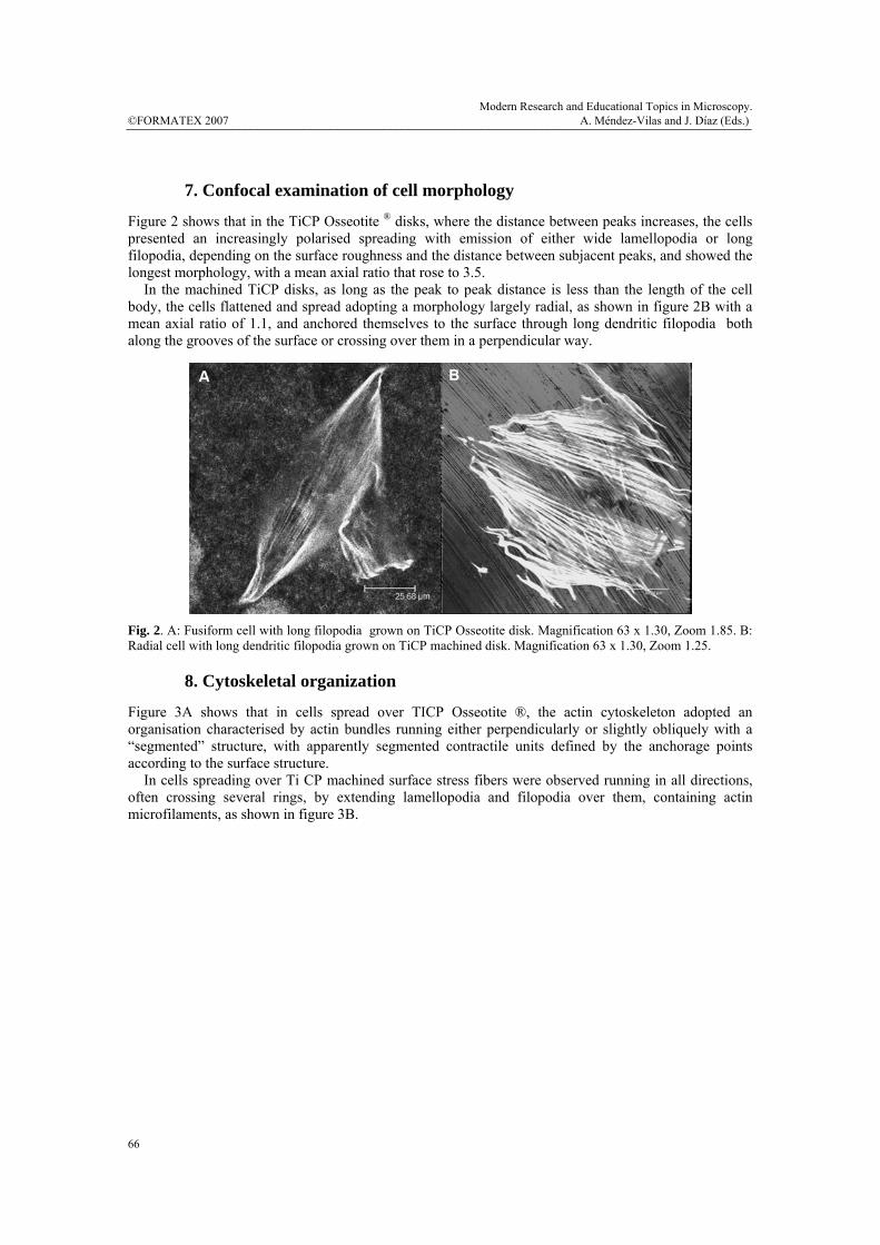
Figure 3A shows that in cells spread over TICP Osseotite ®, the actin cytoskeleton adopted an organisation characterised by actin bundles running either perpendicularly or slightly obliquely with a “segmented” structure, with apparently segmented contractile units defined by the anchorage points according to the surface structure. In cells spreading over Ti CP machined surface stress fibers were observed running in all directions, often crossing several rings, by extending lamellopodia and filopodia over them, containing actin microfilaments, as shown in figure 3B.
©FORMATEX 2007Modern Research and Educational Topics in Microscopy. A. Méndez-Vilas and J. Díaz (Eds.) _______________________________________________________________________________________________
66
Fig. 3. A: TiCP Osseotite disk. Actin cytoskeleton with segmented contractile units defined by the anchorage points (arrows). Magnification 63 x 1.30, Zoom 1.98. B: TiCP machined disk. Stress fibers were observed running in all directions. Magnification 63 x 1.30, Zoom 1.98.
9. Biomedical Applications The last decade has seen dramatical developments of engineered tissues assembled from cells, biomaterials and signalling factors. CLSM combining fluorescence and backscattered modes has revealed to be an useful tool for investigating the dynamics of biological interactions among these components and the mechanisms by which specific structural and mechanical properties of the three dimensional extracellular matrix microenvironment influence cell behaviour. CLSM image combining the fluorescence and reflection modes helped us to illustrate cell-disk interaction and to demonstrate that osteoblasts assume distinct morphologies depending on the architectural features of their substrate. This approach may contribute to a better understanding of the processes involved in the integration of oral implants. Despite the immense success of oral implants and implants in general, implant performance still needs to be improved, especially for patients with an unfavourable prognosis because of impaired bone or soft tissue repair due to underlying diseases.
Acknowledgements The support by a FIS 05/1816 Grant from Instituto de Salud Carlos III, Spain is gratefully acknowledged. The authors want to acknowledge 3i (Palm Beach Gardens, USA) for prefabricating and kindly providing the titanium disks.
References [1] S.L Voytik-Harbin, B.A. Roeder, J.E. Sturgis, K.Kokini, J.P.Robinson . Microscopy. Microanalysis 9, 74
(2003) [2] W.Tan , A. Sendemir-Urkmez, L.J. Fahrner, R. Jamison, D. Leckband and S.A. Boppart. Tissue Engineering.
10, 1747 (2004) [3] W.Tan., C. Vinegoni, J.J. Norman, T.A. Desal and S.A. Boppart. Microscopy Research and Technique 70, 361
(2007) [4] W.Baschong, R. Suetterlin, A. Hefti, H. Schiel. Micron 32, 33 (2001) [5] G. Udupa, M. Singaperumal, R.S. Sirohi, M.P. Kothiyal. Measurement science & technology. 11, 305 (2000) [6] M.S. Sader, A. Balduino, G.A. Soares, R. Borojevic. Clinical oral implants research. 16, 667 (2005) [7] V. Papalexiou, A.B. Novaes, M.F.M. Grisi, S. Souza, M. Taba, J.K. Kajiwara. Clinical oral implants research.
15, 44 (2004) [8] D. Rodriguez-Rius, F.J. Garcia-Saban. Medicina oral, patología oral y cirugía bucal 10, 58 (2005) [9] M.Salido, J.I. Vilches, J.L. Gutiérrez, J. Vilches. Histology and Histopathology, 2007 ( in press) [10] A. Hibbs. Confocal Microscopy for Biologists, (Kluwer, NY; 2004) 3, 66-90. [11] H.E. Keller. In Pawley J.B. ed.(Springer, NY, 2005) 7: 145-160.
Modern Research and Educational Topics in Microscopy. A. Méndez-Vilas and J. Díaz (Eds.) ©FORMATEX 2007 _______________________________________________________________________________________________
67


![Dr. Al-Jadaa TODENTJstatic GEPT values were assessed according to a previously published and validated protocol [5, 9]. 2.1. Mounting of the Implants All implants were mounted in custom](https://static.fdocuments.net/doc/165x107/61337e6adfd10f4dd73b1feb/dr-al-jadaa-static-gept-values-were-assessed-according-to-a-previously-published.jpg)