
Cell Differentiation Induction Using Extracellular
18
4 Cell Differentiation Induction Using Extracellular Stimulation Controlled by a Micro Device Yuta Nakashima 1 , Katsuya Sato 2 , Takashi Yasuda 3 and Kazuyuki Minami 1 1 Yamaguchi University 2 The University of Tokushima 3 Kyushu Institute of Technology Japan 1. Introduction The stem cell differentiation is greatly dependent on the living environment i.e., the cell differentiation determined by timing, amplitude, amount and etc. of stimulation from outside of cells (Lanza & Rosenthal, 2004). If living environment of cell can be controlled artificially by using micro device, we will be able to guide the cell having specific function from stem cells. The micromachining technology allows integration of various mechanical, electrical, and chemical elements, and has produced micro devices that can manipulate chemical solution, small mechanical parts, cells and etc. (Meyer et al., 2000; Takeuchi & Shimoyama, 1999; Nakashima et al., 2010; Nakashima & Yasuda, 2009; Chen et al., 2007; Taff & Voldman, 2005; Choi & Park, 2005; Doh & Cho, 2005). Our purpose is to fabricate micro devices which can control cell differentiation and axon elongation by extracellular stimulation. The cell differentiation induction on the micro devices will be applied to a technique for restoring impaired or lost biological function and controlling differentiation of a stem cell to a specific cell. This paper presents two micro devices intended to control the induction of cell differentiation dynamically by chemical stimulation and mechanical stimulation. First, we present a chemical stimulation device consisting of a microvalve, a nano-holes array, and a chamber, which are placed very close to one another. The amount of chemical solution released from the nano-hole array can be controlled very precisely by opening and closing the microvalve. Also, we show the behavior of cells stimulated using the fabricated chemical stimulation device, i.e., differentiation guidance of cells using release control of nerve growth factor (NGF) which is a protein that enhances axonal outgrowth from a cell body. Next, we present a mechanical stimulation device consisting of a chamber for cell culture and a microlinkage mechanism for applying uniaxial stretching to the microchamber. Then we show the fluorescence observation of behavior of a cell that receives stimulation by fabricated mechanical stimulation device. 2. Chemical stimulation device 2.1 Design of the chemical stimulation device The microdevice we designed for chemical stimulation consists of a nano-hole array for NGF release, a hydrophobic passive microvalve for controlling NGF release, a microchannel www.intechopen.com
Transcript of Cell Differentiation Induction Using Extracellular

4
Cell Differentiation Induction Using Extracellular Stimulation Controlled by a Micro Device
Yuta Nakashima1, Katsuya Sato2, Takashi Yasuda3
and Kazuyuki Minami1 1Yamaguchi University
2The University of Tokushima 3Kyushu Institute of Technology
Japan
1. Introduction
The stem cell differentiation is greatly dependent on the living environment i.e., the cell differentiation determined by timing, amplitude, amount and etc. of stimulation from outside of cells (Lanza & Rosenthal, 2004). If living environment of cell can be controlled artificially by using micro device, we will be able to guide the cell having specific function from stem cells. The micromachining technology allows integration of various mechanical, electrical, and chemical elements, and has produced micro devices that can manipulate chemical solution, small mechanical parts, cells and etc. (Meyer et al., 2000; Takeuchi & Shimoyama, 1999; Nakashima et al., 2010; Nakashima & Yasuda, 2009; Chen et al., 2007; Taff & Voldman, 2005; Choi & Park, 2005; Doh & Cho, 2005). Our purpose is to fabricate micro devices which can control cell differentiation and axon elongation by extracellular stimulation. The cell differentiation induction on the micro devices will be applied to a technique for restoring impaired or lost biological function and controlling differentiation of a stem cell to a specific cell. This paper presents two micro devices intended to control the induction of cell differentiation dynamically by chemical stimulation and mechanical stimulation. First, we present a chemical stimulation device consisting of a microvalve, a nano-holes array, and a chamber, which are placed very close to one another. The amount of chemical solution released from the nano-hole array can be controlled very precisely by opening and closing the microvalve. Also, we show the behavior of cells stimulated using the fabricated chemical stimulation device, i.e., differentiation guidance of cells using release control of nerve growth factor (NGF) which is a protein that enhances axonal outgrowth from a cell body. Next, we present a mechanical stimulation device consisting of a chamber for cell culture and a microlinkage mechanism for applying uniaxial stretching to the microchamber. Then we show the fluorescence observation of behavior of a cell that receives stimulation by fabricated mechanical stimulation device.
2. Chemical stimulation device
2.1 Design of the chemical stimulation device The microdevice we designed for chemical stimulation consists of a nano-hole array for NGF release, a hydrophobic passive microvalve for controlling NGF release, a microchannel
www.intechopen.com
Pheochromocytoma – A New View of the Old Problem
48
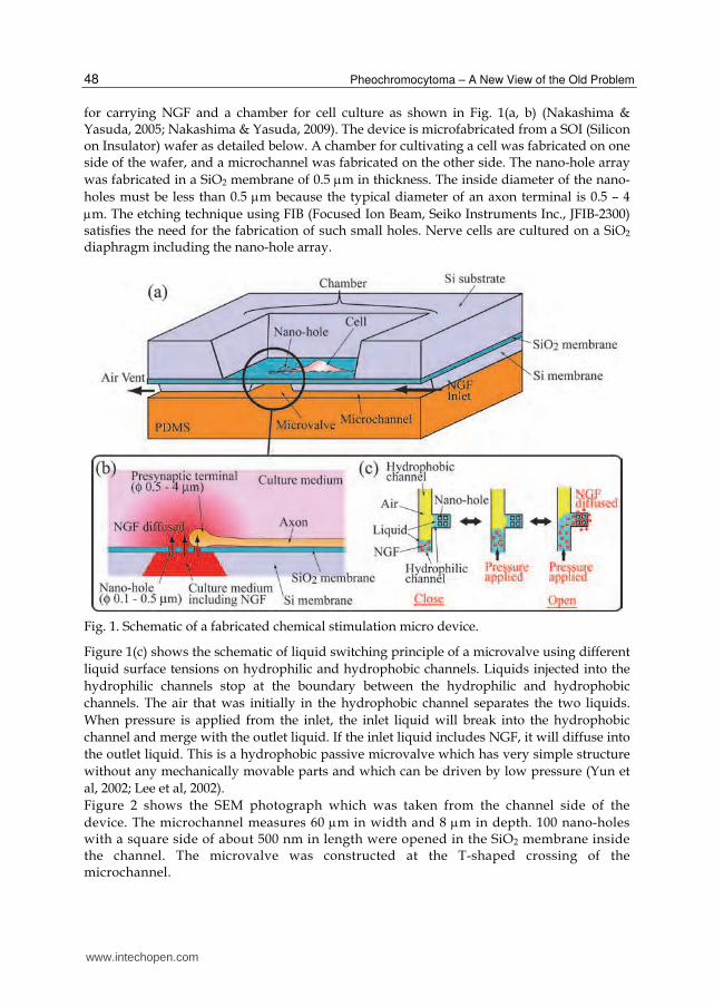
for carrying NGF and a chamber for cell culture as shown in Fig. 1(a, b) (Nakashima & Yasuda, 2005; Nakashima & Yasuda, 2009). The device is microfabricated from a SOI (Silicon on Insulator) wafer as detailed below. A chamber for cultivating a cell was fabricated on one side of the wafer, and a microchannel was fabricated on the other side. The nano-hole array
was fabricated in a SiO2 membrane of 0.5 m in thickness. The inside diameter of the nano-
holes must be less than 0.5 m because the typical diameter of an axon terminal is 0.5 – 4
m. The etching technique using FIB (Focused Ion Beam, Seiko Instruments Inc., JFIB-2300) satisfies the need for the fabrication of such small holes. Nerve cells are cultured on a SiO2 diaphragm including the nano-hole array.
Fig. 1. Schematic of a fabricated chemical stimulation micro device.
Figure 1(c) shows the schematic of liquid switching principle of a microvalve using different
liquid surface tensions on hydrophilic and hydrophobic channels. Liquids injected into the
hydrophilic channels stop at the boundary between the hydrophilic and hydrophobic
channels. The air that was initially in the hydrophobic channel separates the two liquids.
When pressure is applied from the inlet, the inlet liquid will break into the hydrophobic
channel and merge with the outlet liquid. If the inlet liquid includes NGF, it will diffuse into
the outlet liquid. This is a hydrophobic passive microvalve which has very simple structure
without any mechanically movable parts and which can be driven by low pressure (Yun et
al, 2002; Lee et al, 2002).
Figure 2 shows the SEM photograph which was taken from the channel side of the
device. The microchannel measures 60 m in width and 8 m in depth. 100 nano-holes with a square side of about 500 nm in length were opened in the SiO2 membrane inside the channel. The microvalve was constructed at the T-shaped crossing of the microchannel.
www.intechopen.com

Cell Differentiation Induction Using Extracellular Stimulation Controlled by a Micro Device
49
Fig. 2. SEM photographs of the fabricated device. The microchannels including a hydrophobic passive microvalve and nano-hole array.
2.2 Device fabrication Figure 3 shows the fabrication process of the chemical stimulation device. SiO2 films were created by thermal oxidation on both sides of a SOI wafer that consists of 350 m thick
handle Si layer, 500 nm thick SiO2 layer, and 8 m thick Si layer (Fig. 3(a)). The SOI wafer was spin-coated with photoresist ZPN-1150 (ZEON Corp.) on the front side, and the SiO2 film was patterned by photolithography and wet etching. In order to fabricate the culture chamber, the thick Si layer was etched anisotropically (Fig. 3(b)). Next, the microchannel was fabricated by anisotropically etching the backside of Si layer (Fig. 3(c)). Then, the microvalve was fabricated by lift-off method of Au deposition and by creating hydrophobic SAM (self assembled monolayer), 1-octadecanethiol on the Au surface (Fig. 3(d)). The nano-holes were fabricated in a SiO2 membrane by FIB (Fig. 3(e)). Finally, the culture chamber was coated by collagen, and the microchannels were covered with the PDMS sheet.
Fig. 3. Fabrication process of the chemical stimulation device.
www.intechopen.com
Pheochromocytoma – A New View of the Old Problem
50
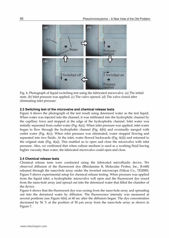
Fig. 4. Photograph of liquid switching test using the fabricated microvalve. (a) The initial state. (b) Inlet pressure was applied. (c) The valve opened. (d) The valve closed after eliminating inlet pressure.
2.3 Switching test of the microvalve and chemical release tests Figure 4 shows the photograph of the test result using deionized water as the test liquid.
When water was injected into the channel, it was infiltrated into the hydrophilic channel by
the capillary force and stopped at the edge of the hydrophobic channel. Inlet water was
initially separated from outlet water (Fig. 4(a)). When inlet pressure was applied, inlet water
began to flow through the hydrophobic channel (Fig. 4(b)) and eventually merged with
outlet water (Fig. 4(c)). When inlet pressure was eliminated, water stopped flowing and
separated into two fluids. At the inlet, water flowed backwards (Fig. 4(d)) and returned to
the original state (Fig. 4(a)). This enabled us to open and close the microvalve with inlet
pressure. Also, we confirmed that when culture medium is used as a working fluid having
higher viscosity than water, the fabricated microvalve could open and close.
2.4 Chemical release tests Chemical release tests were conducted using the fabricated microfluidic device. We
observed diffusion of the fluorescent dye (Rhodamine B, Molecular Probes, Inc., R-648)
released through the nano-hole array under the inverted microscope (Nikon Co., TE2000).
Figure 5 shows experimental setup for chemical release testing. When pressure was applied
from the liquid inlet, a hydrophobic microvalve will open and the fluorescent dye oozed
from the nano-hole array and spread out into the deionized water that filled the chamber of
the device.
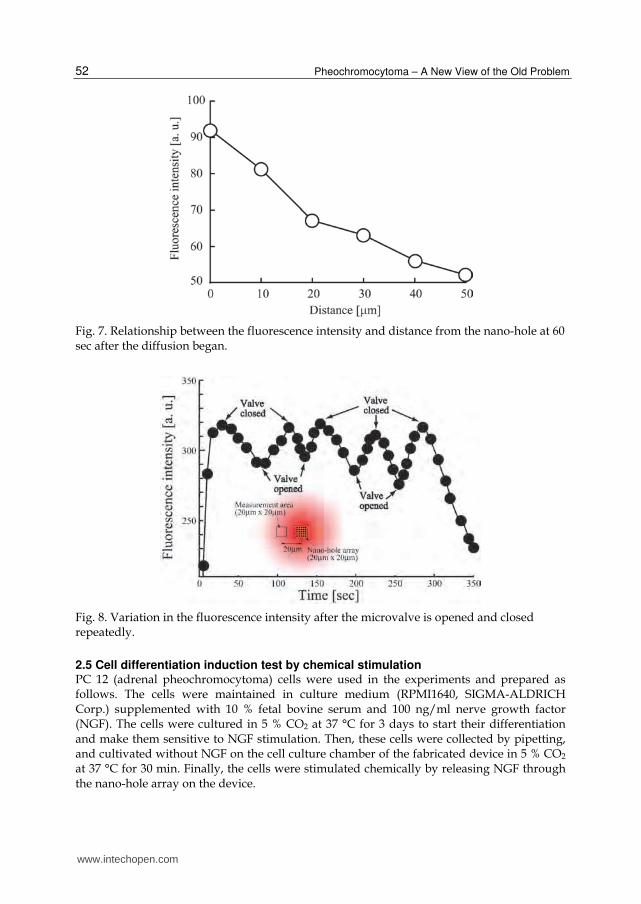
Figure 6 shows that the fluorescent dye was oozing from the nano-hole array and spreading out into the deionized water by diffusion. The fluorescence intensity was measured at several positions (see Figure 6(b)) at 60 sec after the diffusion began. The dye concentration
decreased by 56 % at the position of 50 m away from the nano-hole array as shown in Figure 7.
www.intechopen.com

Cell Differentiation Induction Using Extracellular Stimulation Controlled by a Micro Device
51
Fig. 5. Experimental setup. The fabricated microfluidic device was covered with PDMS film. Diffusion of the fluorescent dye through the nano-hole array was observed under the inverted microscope.
The variation in the fluorescence intensity synchronized with opening and closing of the microvalve as shown in Fig.8. The fluorescence intensity rose immediately after the valve opened, and decreased immediately when the valve was closed. Additionally, the fluorescence intensity changed according to the switching interval, the smaller the fluorescence intensity change. This result means that the fabricated device can control release of chemical solution by opening and closing of the valve.
Fig. 6. Diffusion of fluorescent dye through a nano-hole array. Light gray indicates high concentration of fluorescent dye.
www.intechopen.com
Pheochromocytoma – A New View of the Old Problem
52
Fig. 7. Relationship between the fluorescence intensity and distance from the nano-hole at 60 sec after the diffusion began.
Fig. 8. Variation in the fluorescence intensity after the microvalve is opened and closed repeatedly.
2.5 Cell differentiation induction test by chemical stimulation PC 12 (adrenal pheochromocytoma) cells were used in the experiments and prepared as follows. The cells were maintained in culture medium (RPMI1640, SIGMA-ALDRICH Corp.) supplemented with 10 % fetal bovine serum and 100 ng/ml nerve growth factor (NGF). The cells were cultured in 5 % CO2 at 37 °C for 3 days to start their differentiation and make them sensitive to NGF stimulation. Then, these cells were collected by pipetting, and cultivated without NGF on the cell culture chamber of the fabricated device in 5 % CO2 at 37 °C for 30 min. Finally, the cells were stimulated chemically by releasing NGF through the nano-hole array on the device.
www.intechopen.com

Cell Differentiation Induction Using Extracellular Stimulation Controlled by a Micro Device
53
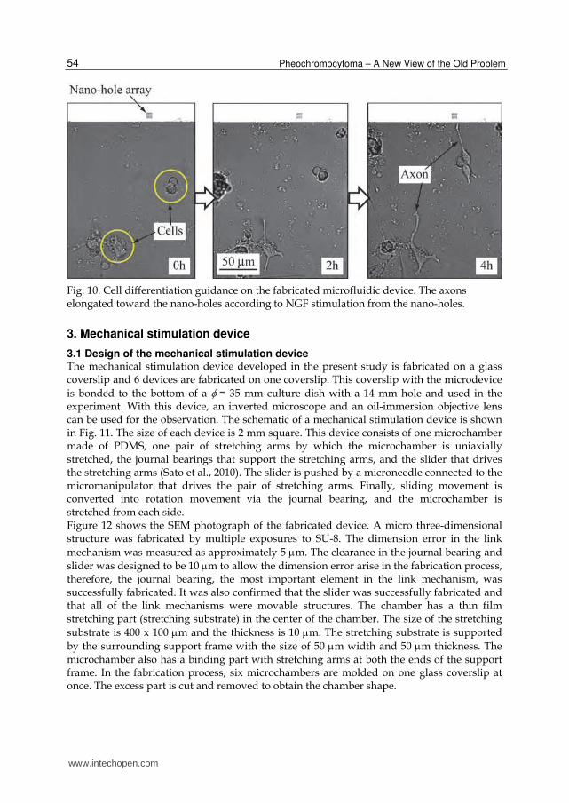
We confirmed whether cell differentiation can be controlled on the device or not. Figure 9 shows experimental procedure for cell differentiation induction. Growth of cells stimulated by NGF is observed under a microscope from the chamber side. The inlet culture medium containing NGF and the culture medium in the cell culture chamber are initially separated by a closed hydrophobic microvalve. When pressure is applied from the inlet, the inlet liquid and the chamber liquid are connected by opening the microvalve. After that, NGF diffused into the chamber liquid and is released into the chamber through the nano-hole array. Thus, the cells in the chamber are stimulated by NGF. We conducted the experiment that was NGF stimulation controlled by periodic switching of the microvalve using the fabricated microdevice. We observed the growth of cultured cells while the microvalve was switched at 1Hz under the inverted microscope. As shown in Fig.10, the lower left cell that adhered to the device surface elongated the axon toward nano-holes as time passed. On the other hand, because the right side cell did not adhere to the device surface at first, it could not begin to differentiate. However, after it succeeded in adhering to the device surface 2 hours after the original stimulus was applied, the right side cell also demonstrated our intended movement manner, i.e. it elongated the axon toward the nano-holes as time passed. From this result, we conclude that we can guide the cell differentiation and the axon elongation by the fabricated microdevice.
Fig. 9. Experimental procedure for cell differentiation induction using fabricated microdevice.
www.intechopen.com
Pheochromocytoma – A New View of the Old Problem
54
Fig. 10. Cell differentiation guidance on the fabricated microfluidic device. The axons elongated toward the nano-holes according to NGF stimulation from the nano-holes.
3. Mechanical stimulation device
3.1 Design of the mechanical stimulation device The mechanical stimulation device developed in the present study is fabricated on a glass coverslip and 6 devices are fabricated on one coverslip. This coverslip with the microdevice
is bonded to the bottom of a = 35 mm culture dish with a 14 mm hole and used in the experiment. With this device, an inverted microscope and an oil-immersion objective lens can be used for the observation. The schematic of a mechanical stimulation device is shown in Fig. 11. The size of each device is 2 mm square. This device consists of one microchamber made of PDMS, one pair of stretching arms by which the microchamber is uniaxially stretched, the journal bearings that support the stretching arms, and the slider that drives the stretching arms (Sato et al., 2010). The slider is pushed by a microneedle connected to the micromanipulator that drives the pair of stretching arms. Finally, sliding movement is converted into rotation movement via the journal bearing, and the microchamber is stretched from each side. Figure 12 shows the SEM photograph of the fabricated device. A micro three-dimensional structure was fabricated by multiple exposures to SU-8. The dimension error in the link
mechanism was measured as approximately 5 m. The clearance in the journal bearing and
slider was designed to be 10 m to allow the dimension error arise in the fabrication process, therefore, the journal bearing, the most important element in the link mechanism, was successfully fabricated. It was also confirmed that the slider was successfully fabricated and that all of the link mechanisms were movable structures. The chamber has a thin film stretching part (stretching substrate) in the center of the chamber. The size of the stretching
substrate is 400 x 100 m and the thickness is 10 m. The stretching substrate is supported
by the surrounding support frame with the size of 50 m width and 50 m thickness. The microchamber also has a binding part with stretching arms at both the ends of the support frame. In the fabrication process, six microchambers are molded on one glass coverslip at once. The excess part is cut and removed to obtain the chamber shape.
www.intechopen.com

Cell Differentiation Induction Using Extracellular Stimulation Controlled by a Micro Device
55
Fig. 11. Schematic of a fabricated mechanical stimulation micro device.
Fig. 12. SEM photograph of the fabricated mechanical stimulation micro device.
www.intechopen.com

Pheochromocytoma – A New View of the Old Problem
56
3.2 Device fabrication The fabrication process of the device consists of two processes. One is the micromolding of silicone elastomer (PDMS) to fabricate the microchamber. The other is the patterning of thick photoresist to fabricate the link mechanism. The microchamber is made of transparent PDMS enable the observation using the inverted microscope. Although PDMS is generally used in the experiment of applying stretching deformation as a mechanical stimulus to cells (Costa et al., 2002), its chemical stability makes it difficult to shape by a microfabrication technique such as etching. Therefore, we adopted micromolding to fabricate the microchamber. The fabrication process is shown in Fig. 13, and an outline of the process is described below. In the first step of the fabrication process of the microchamber, an original model of the microchamber for molding is prepared. The photoresist (SU-8, Kayaku MicroChem Co., Ltd)
is spin-coated to 10 m thickness (Fig. 13(a, b)), exposed and developed to pattern the
stretching substrate (Fig. 13(c)). A second layer of SU-8 with 50 m thickness is spin-coated onto the first layer (Fig. 13(d)), exposed and developed to pattern the support frame (Fig. 13(e)). By these two steps, an original model of the microchamber is obtained. In the next step, following the fabrication of the original model, the fluorine polymer is sprayed onto the original model to form very thin layer as mold-releasing agents (Fig. 13(f)). PDMS (KE-106, Shin-etsu Silicone) is casted on the original model to obtain a mold transcribed with the shape of the original model (Fig. 13(g)). The obtained mold is again sprayed with fluorine polymer, and punched to form the gate for molding (Fig. 13(h, i)). Finally, the microchamber made of PDMS is molded by using the obtained mold. The link mechanism is fabricated by the multilayer SU-8-based MEMS process (Foulds, I.G. & Parameswaran, M, 2006). This fabrication process includes multiple exposures to obtain movable three-dimensional microstructures.
Fig. 13. Fabrication process of the original model and the micromold for the fabricated microchamber.
www.intechopen.com

Cell Differentiation Induction Using Extracellular Stimulation Controlled by a Micro Device
57
The fabrication process chart is shown in Fig. 14, and an outline of the process is described below. First, Ge is sputtered onto the glass coverslip and patterned as the sacrificial layer by which the microchamber (Fig. 14(j)), stretching arms and slider part are rendered movable. The PDMS microchamber is molded on the Ge-patterned coverslip (Fig. 14(l-n)). The first
layer of SU-8 is spin-coated to 100 m thickness (Fig. 14(o)), and exposed using the photomask of the link mechanism pattern (Fig. 14(p). In addition, without development, the
second layer of SU-8 is spin-coated to 50 m thickness on the first layer (Fig. 14(q)). The second exposure is applied to pattern the axis of the journal bearing (Fig. 14(r)). Finally, the surface exposure technique is applied to fabricate the stopper of the journal bearing (Fig. 14(s)). After the curing and the development of the entire device structure (Fig. 14(t)), the Ge sacrificial layer is removed and the link mechanism is completed (Fig. 14(u)).
Fig. 14. Fabrication process of the microlink mechanism for mechanical stimulation device.
www.intechopen.com

Pheochromocytoma – A New View of the Old Problem
58
3.3 Operation test of mechanical stimulation device The fabricated device on the glass coverslip was immersed in DI (deionized) water and tested. Figure 15 shows the image during the operation test using an inverted phase-contrast microscope (Olympus Co., CKX-41). Figure 15(a) shows the initial state of the device. Figure 15(b) shows the state after the slider was pushed by tweezers and the microchamber was stretched from both ends in the directions to the right and lift in the figure. It was shown that the fabricated device was actually able to work under observation using the inverted optical microscope.
Fig. 15. Operating image of mechanical stimulation device. (a) The initial state. (b) The stretched state.
3.4 Cell stretching test by the mechanical stimulation device We carried out the biocompatibility test by cell culture on the fabricated mechanical stimulation device. The cells were incubated using D-MEM with 10 % FBS (Fetal Bovine Serum), and in 37 °C, humidified 95 % air-5 % CO2 atmosphere. In the preparation for the test, cultured cells were seeded into the dish with the built-in cell-stretching microdevices, and incubated for 8h. After the preincubation, fluorescent indictor dye Fluo 3 was loaded to
the cell as the observation marker by incubating the cell in the opti-MEM containing 12 M Fluo 3-AM (Dojindo) for 30 min. After loading the indicator dye, the cells were rinsed twice with PBS (phosphate buffered saline), and used for the test in normal culture medium. The epifluorescent inverted microscope was used for observation with a x 60 oil immersion objective lens. Figure 16 shows the time lapse image of the stimulated single cell cultured on the chamber. For the sequential stretching operation, Fig. 16(b) shows an image immediately before the operation where we define t = 0.0 s. Cells are located slightly above the center in the figure. Two particles slightly below the center are dust particles of fluorescence dye. Figure 16(c) shows an image immediately after the stretching operation, t = 0.1 s. Stretching operation was continued to t = 0.7 s (Fig. 16(f)) and the amount of maximum nominal tensile strain in stretching axis was roughly estimated as 13 % by measuring the displacement of dust
www.intechopen.com

Cell Differentiation Induction Using Extracellular Stimulation Controlled by a Micro Device
59
Fig. 16. Sequential time lapse images of a single cell uniaxially stretched using mechanical stimulation micro device. Dark gray indicates higher fluorescent intensity.
www.intechopen.com

Pheochromocytoma – A New View of the Old Problem
60
particles. Immediately after the maximum stretching, the stretching operation was stopped,
and the microchamber returned to the initial state at t = 1.7 s (Fig. 16(h)). As a result, the cell
successfully adhered to the stretched substrate and received the stretching stimulation in the
microchamber. This result indicates that the fabricated mechanical stimulation device is
biocompatible and able to apply dynamic mechanical stimulus to a cell. Also, the observed
cell stayed in the field of view, indicating that this device can reduce the rigid displacement
of the cell during the stretching operation. Therefore, this device can be used in the
observation experiments of reaction to a mechanical stimulus of a cell such as the alteration
of cellular morphology and cell differentiation induction.
4. Conclusions
This paper demonstrated that two micro devices for dynamic cell differentiation induction.
First, we demonstrated that a chemical stimulation micro device consisting of nano-hole
array for chemical release and a hydrophobic passive microvalve for its release control is
effective in controlling NGF concentration that is required to control stimulation to a cell.
Release of chemical solution such as culture medium could be controlled precisely by
opening and closing the microvalve because the microvalve was placed very close to the
nano-hole array. Furthermore, we succeeded in cell differentiation guidance by controlling
NGF release from nano-hole array.
On the other hand, we evaluated the performance of the mechanical stimulation micro
device consisting of the culture chamber, the stretching arms, the journal bearings and the
slider. Mechanical stimulation to a cell can be controlled by regulating of the chamber
contraction with the slider operation. We succeeded in observation of the single cell reaction
behavior stimulated by stretching. This result indicated this device can induce the cell
differentiation by stimulation control based on cellular reaction.
These devices are able to evaluate the response and morphology transformation of
pheochromocytoma based on the chemical/mechanical stimulation. Also, these results
suggest that the fabricated two devices can dynamically induce the stem cell differentiation
by controlling chemical and mechanical stimulation.
5. Acknowledgment
This work was partly supported by a fund from the MEXT (Ministry of Education, Culture,
Sports, Science and Technology) via the Grant-in-Aid for Scientific Research (B) and for
Young Scientists (B), and also by the “Development of Nanotechnology and Materials for
Innovative Utilizations of Biological Functions“ Project of the Ministry of Agriculture,
Forestry and Fisheries of Japan.
6. References
Lanza, R. & Rosenthal, N. (2004). Scientific American, Nature America Inc., ISBN 0036-8733,
America
Meyer, J.-U.; Schuttler, M.; Thielecke, H. & Stieglitz, T. (2000). Biomedical Microdevices for
Neural Interfaces. Proceedings of the 1st Annual international IEEE-EMBS Special Topic
www.intechopen.com
Cell Differentiation Induction Using Extracellular Stimulation Controlled by a Micro Device
61
Conference on Microtechnologies in Medicine and Biology, ISBN 0-7803-6603-4, Lyon,
France, August 2000
Takeuchi, S. & Shimoyama, I. (1999). Three Dimensional SMA Microelectrodes with
Cliipping Structure for Insect Neural Recording. Technical Digest of the twelfth IEEE
International Conference on Micro Electro Mechanical Systems, ISBN 0-7803-5194-0,
Orlando, FL, January 1999
Nakashima, Y.; Hata, S. & Yasuda, T. (2010). Blood Plasma Separation and Extraction from a
Minute Amount of Blood Using Dielectrophoretic and Capillary Forces. Sensors and
Actuators B: Chemical, No. 145, (2010), pp. 561-569, ISSN 9025-4005
Nakashima, Y. & Yasuda, T. (2009). Parallel Preparation of Microliquid Mixtures Using
Wettability Gradient and Electrowetting, Proceedings of the Micro Total Analysis
Systems Symposium 2009, ISSN 1556-5904, Jeju, Korea, November 2009
Chen, D.F.; Du, H., & Li, W.H. (2007). Bioparticle Separation and Manipulation Using
Dielectrophoresis. Sensors and Actuators A: Phisical, 133, (2007), pp. 329-334, ISSN
9024-4247
Taff, B.M. & Voldman, J. (2005). A scalable addressable posirive-dielectrophoretic cellsorting
array. Analytical Chemistry, 77, 24, (2005), pp. 7976-7983, ISSN 1520-6882
Choi, S. & Park, J.K. (2005). Microfluidic System for Dielectrophoretic Separation Based on a
Trapezoidal Electrode Array. Lab on a Chip, 5, (2005), pp. 1161-1167, ISSN 1473-
0189
Doh, I. & Cho, Y.H. (2005). A Continuous Cell Separation Chip Using Hydrodynamic
Dielectrophoresis Process. Sensors and Actuators A: Phisical, 121, (2005), pp. 59-65,
ISSN 9024-4247
Nakashima, Y. & Yasuda, T. (2002). Fabrication of a Microfluidic Device for Axonal
Guidance. Journal of Robotics and Mechatoronics, Vol. 17, No. 2, (April 2005), pp. 158-
163, ISSN 0915-3942
Yun, K.-S.; Lee, S.-I.; Lee, G.M., & Yoon, E. (2002). Design and fabrication of micro/nano-
fluidic chip performing single-cell positioning and nanoliter drug injection for
single-cell analysis. Proceedings of the Micro Total Analysis Systems Symposium 2002,
ISSN 1556-5904, Nara, Japan, November 2002
Lee, N.Y.; Yamada, M., & Seki, M. (2002). Improved sample injection method adapting
hydrophobic passive valve systems for microfluidic devices. Proceedings of the Micro
Total Analysis Systems Symposium 2002, ISSN 1556-5904, Nara, Japan, November
2002
Nakashima, Y. & Yasuda, T. (2007). Cell Differentiation Guidance Using Chemical
Stimulation Controlled by a Microfluidic Device. Sensors and Actuators A: Physical,
139, (June 2007), pp. 252-258, ISSN 0924-4247
Sato, K.; Kamada, S. & Minami, K. (2010). Development of Microstretching Device to
Evaluate Cell Membrane Strain Field Around Sensing Point of Mechanical
Stimulation. International Journal of Mechanical Sciences, 52, (2010), pp. 251-256, ISSN
0020-7403
Costa, K.D.; Hucker W.J., & Yin, FC-P. (2002). Buckling of Actin Stress Fibers: a New
Wrinkkle in The Cytoskeletal Tapestry. Cell Motility and the Cytoskeleton, 52, (2002),
pp. 266-274, ISSN 1097-0169
www.intechopen.com

Pheochromocytoma – A New View of the Old Problem
62
Foulds, I.G. & Parameswaran, M. (2006). A Planar Self-sacrificial Multilayer SU-8-based
MEMS Process Utilizing a UV-blocking Layer for the Creation of Freely Moving
Parts. Journal of Micromechanics and Microengineering, 16, (2006), pp. 2109-2115, ISSN
0960-1317
www.intechopen.com

Pheochromocytoma - A New View of the Old ProblemEdited by Dr. Jose Fernando Martin
ISBN 978-953-307-822-9Hard cover, 164 pagesPublisher InTechPublished online 16, December, 2011Published in print edition December, 2011
InTech EuropeUniversity Campus STeP Ri Slavka Krautzeka 83/A 51000 Rijeka, Croatia Phone: +385 (51) 770 447 Fax: +385 (51) 686 166www.intechopen.com
InTech ChinaUnit 405, Office Block, Hotel Equatorial Shanghai No.65, Yan An Road (West), Shanghai, 200040, China
Phone: +86-21-62489820 Fax: +86-21-62489821
The book is divided into six sections. The first three sections focus on the pathophysiology of the disease,showing anatomo- and histopathological aspects, experimental models and signaling pathways andprogrammed cell death related to pheochromocytoma. The fourth discusses some specific aspects of clinicalpresentation, with emphasis on clinical manifestations of headache and heart. The fifth section focuses onclinical diagnosis, laboratory and imaging, including differential diagnosis. Finally, the last section discusses thetreatment of pheochromocytoma showing clinical cases, a case about undiagnosed pheochromocytomacomplicated with multiple organ failure and other cases about catecholamine-secreting hereditary tumors.Thus, this book shows the disease "pheochromocytoma" in a different perspective from the traditionalapproach. Enjoy your reading.
How to referenceIn order to correctly reference this scholarly work, feel free to copy and paste the following:
Yuta Nakashima, Katsuya Sato, Takashi Yasuda and Kazuyuki Minami (2011). Cell Differentiation InductionUsing Extracellular Stimulation Controlled by a Micro Device, Pheochromocytoma - A New View of the OldProblem, Dr. Jose Fernando Martin (Ed.), ISBN: 978-953-307-822-9, InTech, Available from:http://www.intechopen.com/books/pheochromocytoma-a-new-view-of-the-old-problem/cell-differentiation-induction-using-extracellular-stimulation-controlled-by-a-micro-device

© 2011 The Author(s). Licensee IntechOpen. This is an open access articledistributed under the terms of the Creative Commons Attribution 3.0License, which permits unrestricted use, distribution, and reproduction inany medium, provided the original work is properly cited.


![Induction of Erythroid Differentiation in Human Leukemic K ......[CANCER RESEARCH 50, 1231-1236. February 15. 1990] Induction of Erythroid Differentiation in Human Leukemic K-562 Cells](https://static.fdocuments.net/doc/165x107/60b088961b1fcf1e2a746f9b/induction-of-erythroid-differentiation-in-human-leukemic-k-cancer-research.jpg)