Ceiling Mount Plate - Placement Considerations and ... · Ceiling Plate False Ceiling Gantry Floor...
30
PORTEGRA2 Pre-Installation & Room Planning Guide Revision XD100E2
Transcript of Ceiling Mount Plate - Placement Considerations and ... · Ceiling Plate False Ceiling Gantry Floor...
PORTEGRA2 Pre-Installation & Room Planning Guide
Revision XD100E2

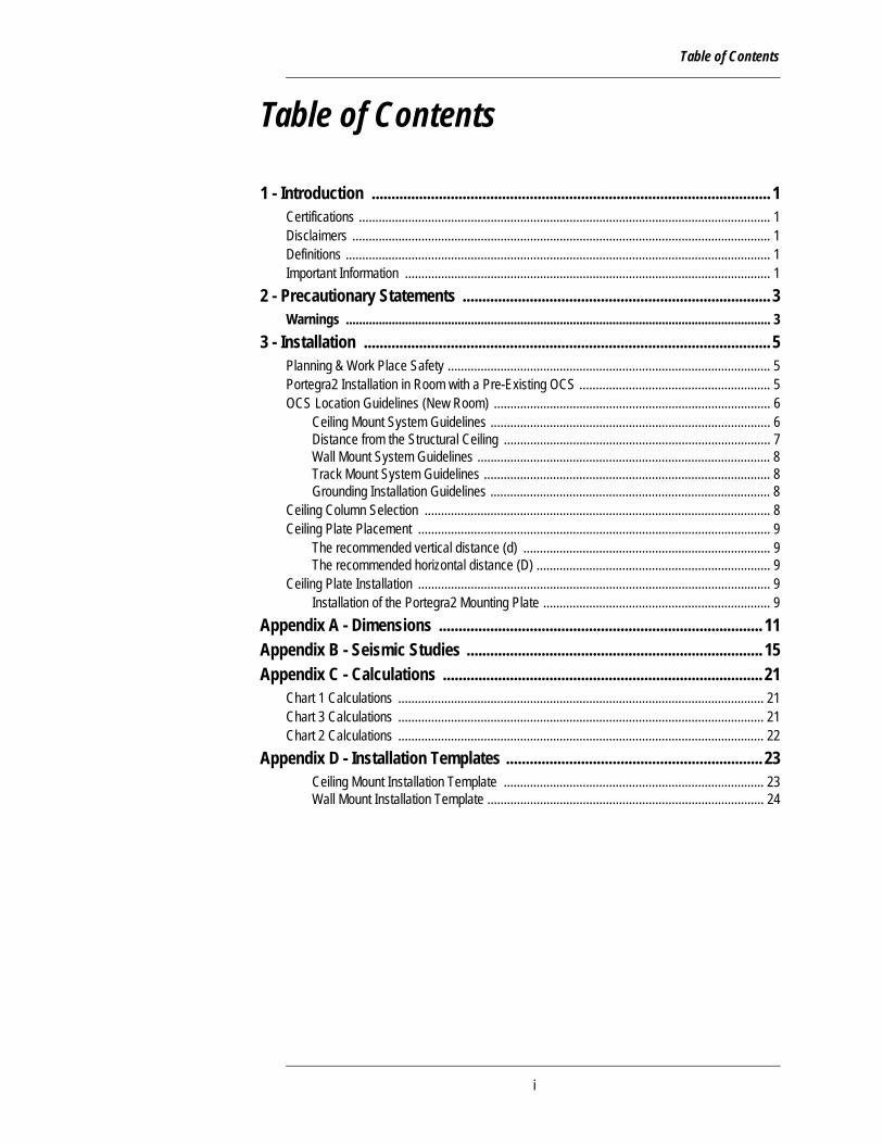
Table of Contents
Table of Contents
1 - Introduction ..................................................................................................... 1Certifications ............................................................................................................................. 1Disclaimers ............................................................................................................................... 1Definitions ................................................................................................................................. 1Important Information ............................................................................................................... 1
2 - Precautionary Statements .............................................................................. 3Warnings ................................................................................................................................. 3
3 - Installation ....................................................................................................... 5Planning & Work Place Safety .................................................................................................. 5Portegra2 Installation in Room with a Pre-Existing OCS .......................................................... 5OCS Location Guidelines (New Room) .................................................................................... 6
Ceiling Mount System Guidelines ..................................................................................... 6Distance from the Structural Ceiling ................................................................................. 7Wall Mount System Guidelines ......................................................................................... 8Track Mount System Guidelines ....................................................................................... 8Grounding Installation Guidelines ..................................................................................... 8
Ceiling Column Selection ......................................................................................................... 8Ceiling Plate Placement ........................................................................................................... 9
The recommended vertical distance (d) ........................................................................... 9The recommended horizontal distance (D) ....................................................................... 9
Ceiling Plate Installation ........................................................................................................... 9Installation of the Portegra2 Mounting Plate ..................................................................... 9
Appendix A - Dimensions .................................................................................. 11Appendix B - Seismic Studies ........................................................................... 15Appendix C - Calculations ................................................................................. 21
Chart 1 Calculations ............................................................................................................... 21Chart 3 Calculations ............................................................................................................... 21Chart 2 Calculations ............................................................................................................... 22
Appendix D - Installation Templates ................................................................. 23Ceiling Mount Installation Template ............................................................................... 23Wall Mount Installation Template .................................................................................... 24
ii

MAVIG PORTEGRA2 Ceiling Plate
ii ii
1 - Introduction
1 - Introduction
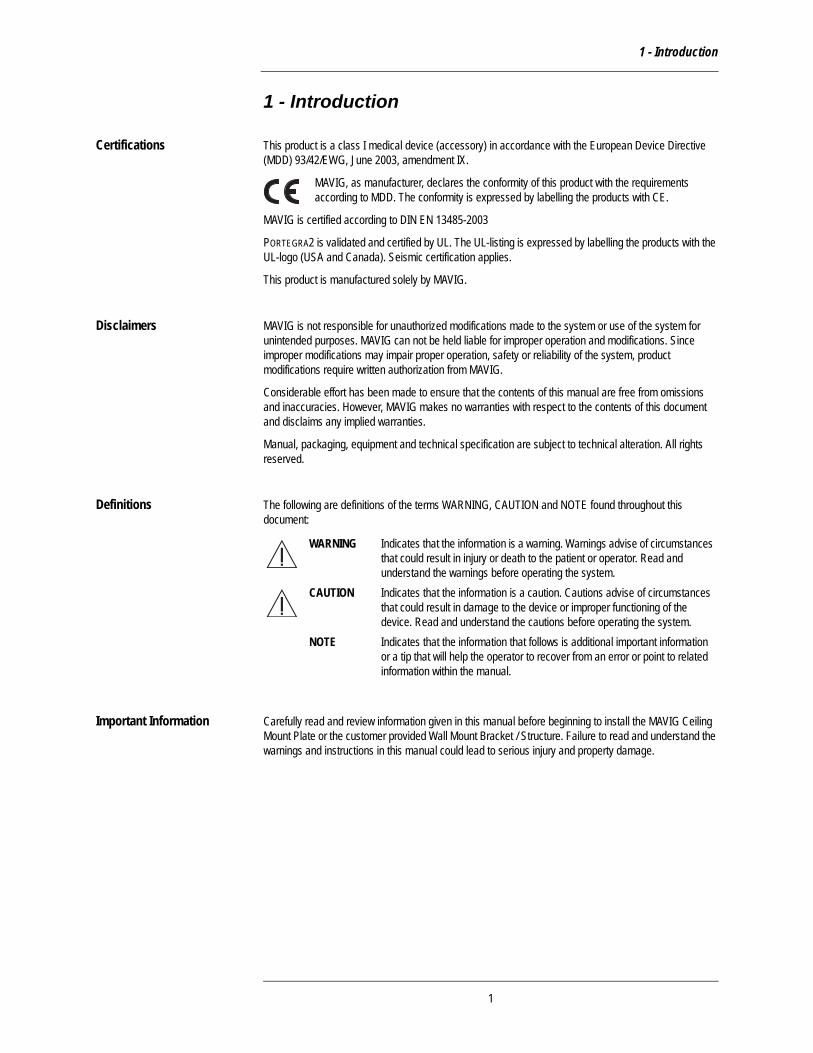
Certifications This product is a class I medical device (accessory) in accordance with the European Device Directive (MDD) 93/42/EWG, June 2003, amendment IX.
MAVIG, as manufacturer, declares the conformity of this product with the requirements according to MDD. The conformity is expressed by labelling the products with CE.
MAVIG is certified according to DIN EN 13485-2003
PORTEGRA2 is validated and certified by UL. The UL-listing is expressed by labelling the products with the UL-logo (USA and Canada). Seismic certification applies.
This product is manufactured solely by MAVIG.
Disclaimers MAVIG is not responsible for unauthorized modifications made to the system or use of the system for unintended purposes. MAVIG can not be held liable for improper operation and modifications. Since improper modifications may impair proper operation, safety or reliability of the system, product modifications require written authorization from MAVIG.
Considerable effort has been made to ensure that the contents of this manual are free from omissions and inaccuracies. However, MAVIG makes no warranties with respect to the contents of this document and disclaims any implied warranties.
Manual, packaging, equipment and technical specification are subject to technical alteration. All rights reserved.
Definitions The following are definitions of the terms WARNING, CAUTION and NOTE found throughout this document:
Important Information Carefully read and review information given in this manual before beginning to install the MAVIG Ceiling Mount Plate or the customer provided Wall Mount Bracket / Structure. Failure to read and understand the warnings and instructions in this manual could lead to serious injury and property damage.
WARNING Indicates that the information is a warning. Warnings advise of circumstances that could result in injury or death to the patient or operator. Read and understand the warnings before operating the system.
CAUTION Indicates that the information is a caution. Cautions advise of circumstances that could result in damage to the device or improper functioning of the device. Read and understand the cautions before operating the system.
NOTE Indicates that the information that follows is additional important information or a tip that will help the operator to recover from an error or point to related information within the manual.
1

MAVIG PORTEGRA2 Ceiling Plate
2
2 - Precautionary Statements
2 - Precautionary Statements
MAVIG emphasizes that prior to installation, a structural engineer must certify that the rough ceiling or wall structure is sufficiently strong to provide proper support for the system. Installation must be completed according to local building codes. Failure to follow these procedures will release MAVIG from responsibility for damages of any sort.
For details, also refer to the attached seismic information.
Ceiling and wall mounted systems must be installed properly. Failure to follow the provided instructions may lead to a potentially dangerous and unstable condition of the system.
Warnings WARNING: Electrical connections, installation, removal and repair of the MAVIG Portegra2 must be performed by a qualified, licensed technician.
WARNING: Overhead Counterpoise System (OCS) units are made of ferrous materials. In a strong magnetic field, the OCS will be forcefully pulled in an unpredictable manner. Do not install in MRI rooms.
Determination of required installation hardware and torque values for installation of the ceiling plate track mount and wall mount bracket is the sole responsibility of structural engineer.
The protective covers on pins not equipped with arms should always be in place.
This product should be serviced with manufacturer approved original replacement parts. Failure to follow this recommendation will void the manufacturer’s warranty and will release the manufacturer from all liability and warranty claims.
The PORTEGRA2 system is only validated and approved by MAVIG for the following CE-devices: radiation protection shields, LCD suspensions, injector holders and "M" exam lights.
NOTE: MAVIG PORTEGRA2 systems are built and validated for use with MAVIG original devices or devices that have been validated by MAVIG. Only MAVIG original devices or those devices that have been validated are optimized and equipped with all necessary safety features. MAVIG cannot accept any warranty or liability for non-MAVIG devices attached to PORTEGRA2 systems unless MAVIG has validated and approved such device.
3

MAVIG PORTEGRA2 Ceiling Plate
4

3 - Installation
3 - Installation
Planning & Work Place Safety
The MAVIG PORTEGRA2 OCS System can be installed using a Ceiling Plate, a Track System or a Wall Mount Bracket.
Prior to installation, a structural engineer must certify that the rough structural ceiling or wall structure is sufficiently strong to provide proper support to the system. Verify that the installation complies with local requirements. Ensure installation is done in accordance with the seismic study reports found in this document.
The MAVIG PORTEGRA2 ceiling or wall mounting plates must be installed to the structural support. Using a substitute mounting plate is not acceptable. This plate can be included in the shipment when a PORTEGRA2 is ordered. It is also possible to order this plate ahead of time for installation by the structural engineer / architect prior to installation of the MAVIG PORTEGRA2.
If the customer has already ordered a ceiling column as part of a PORTEGRA2 system, please ensure that it reflects the recommendations presented in this guide.
Installation of the ceiling or wall plate and ceiling column, along with the appropriate installation hardware must be completed according to local building codes.
All local work and safety regulations must be observed.
PORTEGRA2 Installation in Room with a Pre-Existing OCS
The strategy to be followed if another Overhead Counterpoise System (OCS) was previously installed in the room is detailed below. MAVIG can not provide guidance on using the existing support structure or ceiling plate. This determination must be made by a structural engineer or architect. In either case, a new PORTEGRA2 ceiling plate must be used. Any existing plate must be disposed of properly.
If a MAVIG OCS was installed please see the guidelines below for use of the previous support structure and ceiling plate. It is possible to use the existing support structure but not the existing ceiling plate. The following precautions should be taken:
• Verify the dimensions, pivot points and degrees of freedom and all other specifications contained in Appendix A to ensure that the new PORTEGRA2 will fit in the same location as the previous system.
• Remove the currently installed ceiling plate and dispose of it. Verify that the hole pattern in the new PORTEGRA2 ceiling plate matches the hole pattern for the prior system support structure.
• The support structure must be inspected by a qualified Structural Engineer and or Architect to ensure that it is plumb and level to within 1 degree and that it can support the load as detailed in the seismic study.
• Once the above steps are confirmed have the Structural Engineer and or Architect install the new PORTEGRA2 ceiling plate on the support structure. The Structural Engineer / Architect must install the PORTEGRA2 ceiling plate. The PORTEGRA2 cannot be installed without the ceiling plate, and cannot be installed with a substitute ceiling plate.
• The new PORTEGRA2 can now be installed on the new ceiling plate. • See chart 1 for suggested ceiling columns.
5
MAVIG PORTEGRA2 Ceiling Plate
OCS Location Guidelines (New Room)
The OCS ceiling plate, track mount and wall mount plate should always be installed by a qualified Structural Engineer and or Architect. The customer is responsible for working with the Structural Engineer and or Architect to place the OCS within the Scanner room. The customer is responsible for working with the structural engineer and/or architect to design and install any additional structural support for the mounting plate or brackets. Appendix A of the room planning guide provides detailed information on the dimensions, pivot points, and degrees of freedom of each pivot point. This information should be reviewed prior to locating the OCS and selecting the ceiling column. The information provided below for locating the OCS system within the Scanner room and selecting the ceiling column has been provided for guidance.
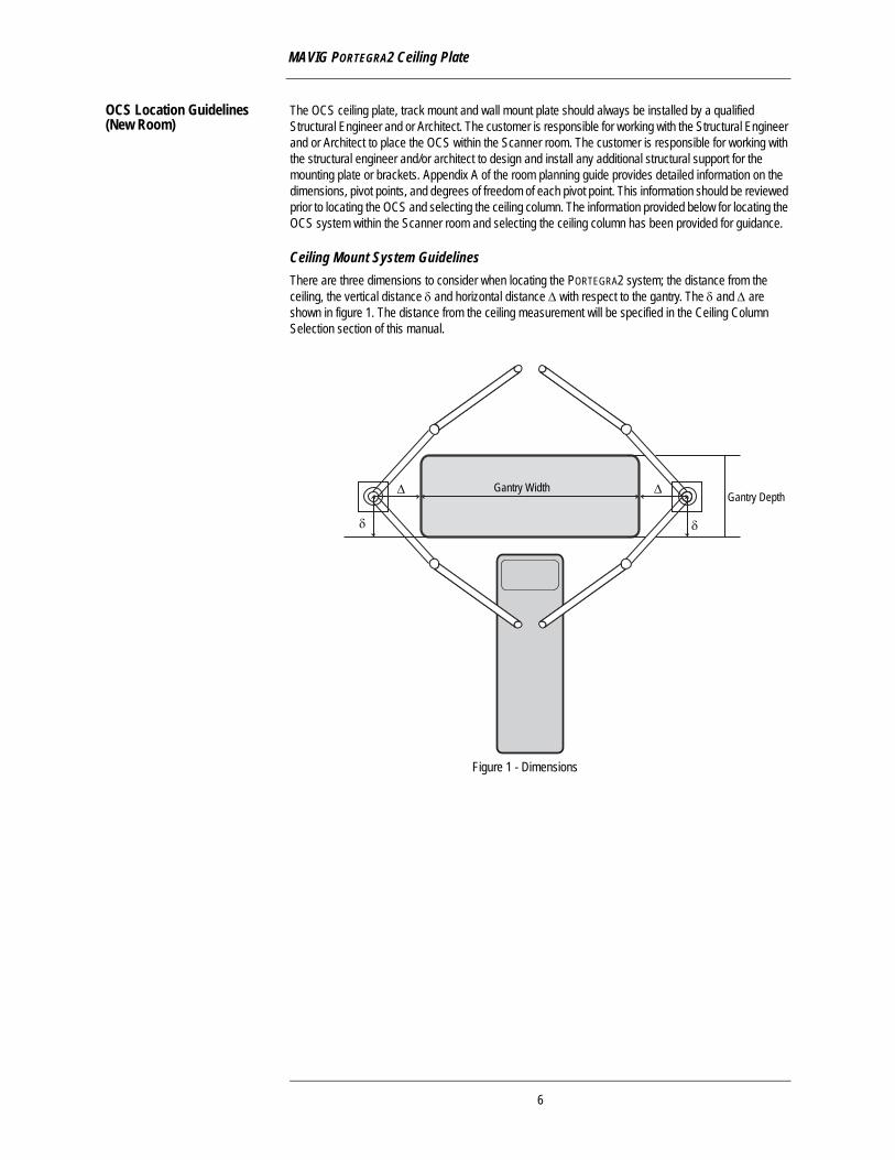
Ceiling Mount System GuidelinesThere are three dimensions to consider when locating the PORTEGRA2 system; the distance from the ceiling, the vertical distance δ and horizontal distance Δ with respect to the gantry. The δ and Δ are shown in figure 1. The distance from the ceiling measurement will be specified in the Ceiling Column Selection section of this manual.
Gantry DepthGantry Width
Figure 1 - Dimensions
Δ Δ
δδ
6
3 - Installation
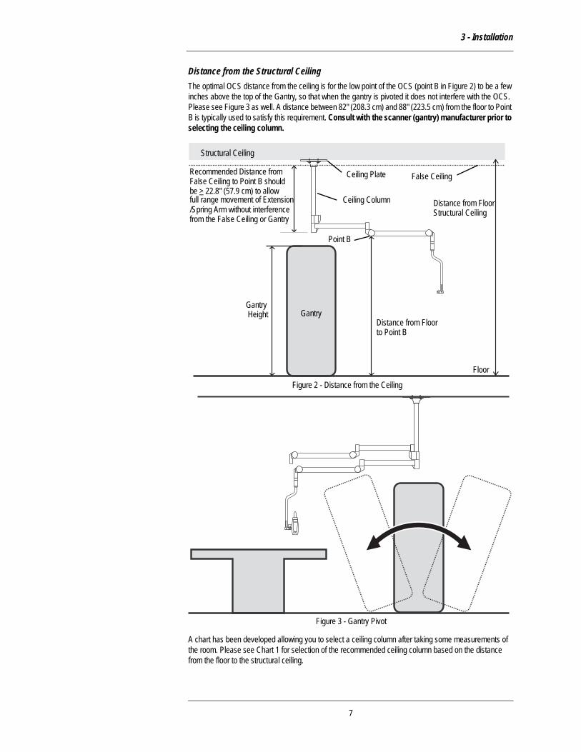
Distance from the Structural CeilingThe optimal OCS distance from the ceiling is for the low point of the OCS (point B in Figure 2) to be a few inches above the top of the Gantry, so that when the gantry is pivoted it does not interfere with the OCS. Please see Figure 3 as well. A distance between 82" (208.3 cm) and 88" (223.5 cm) from the floor to Point B is typically used to satisfy this requirement. Consult with the scanner (gantry) manufacturer prior to selecting the ceiling column.
A chart has been developed allowing you to select a ceiling column after taking some measurements of the room. Please see Chart 1 for selection of the recommended ceiling column based on the distance from the floor to the structural ceiling.
Figure 3 - Gantry Pivot
Structural Ceiling
False CeilingCeiling Plate
Gantry
Floor
GantryHeight
Distance from Floorto Point B
Point B
Figure 2 - Distance from the Ceiling
Distance from FloorStructural Ceiling
Recommended Distance from
Ceiling Column
False Ceiling to Point B should be > 22.8" (57.9 cm) to allow full range movement of Extension /Spring Arm without interference from the False Ceiling or Gantry
7
MAVIG PORTEGRA2 Ceiling Plate
Wall Mount System GuidelinesThe MAVIG PORTEGRA2 OCS System can be installed to a Wall Mount Bracket. This bracket should be mounted at a height to provide a clearance of 82" (208.3 cm) from the floor to Point B (Refer to Figure 2 for Point B). Refer to appendix D of this manual for Mounting Template. Contact MAVIG for any additional mounting information.
Track Mount System GuidelinesThe MAVIG PORTEGRA2 OCS System can be installed to a Track Mount Trolley System. The Trolley Mount Column is available in two lengths, 22.8" (580 mm) and 31.5" (800 mm). The selection of the Trolley Mount Column length is based on the height of the Track System to ensure proper clearance from the Gantry or other room equipment (shields, lamps etc.). The column should be chosen to provide a clearance of 82" (208.3 cm) from the floor to Point B (Refer to Figure 2 for Point B).
Grounding Installation GuidelinesAll electrical connections of the ceiling column must be performed by licensed or qualified personnel according to local regulations (such as NFPA-99 or National Electrical Code NEC).
Connect External Grounding Cable (10 AWG or larger) to keep resistance from Ground Reference Point to MAVIG PORTEGRA2 OCS System Ground Stud to a minimum. Ideally, this resistance should be < 50 mohm.
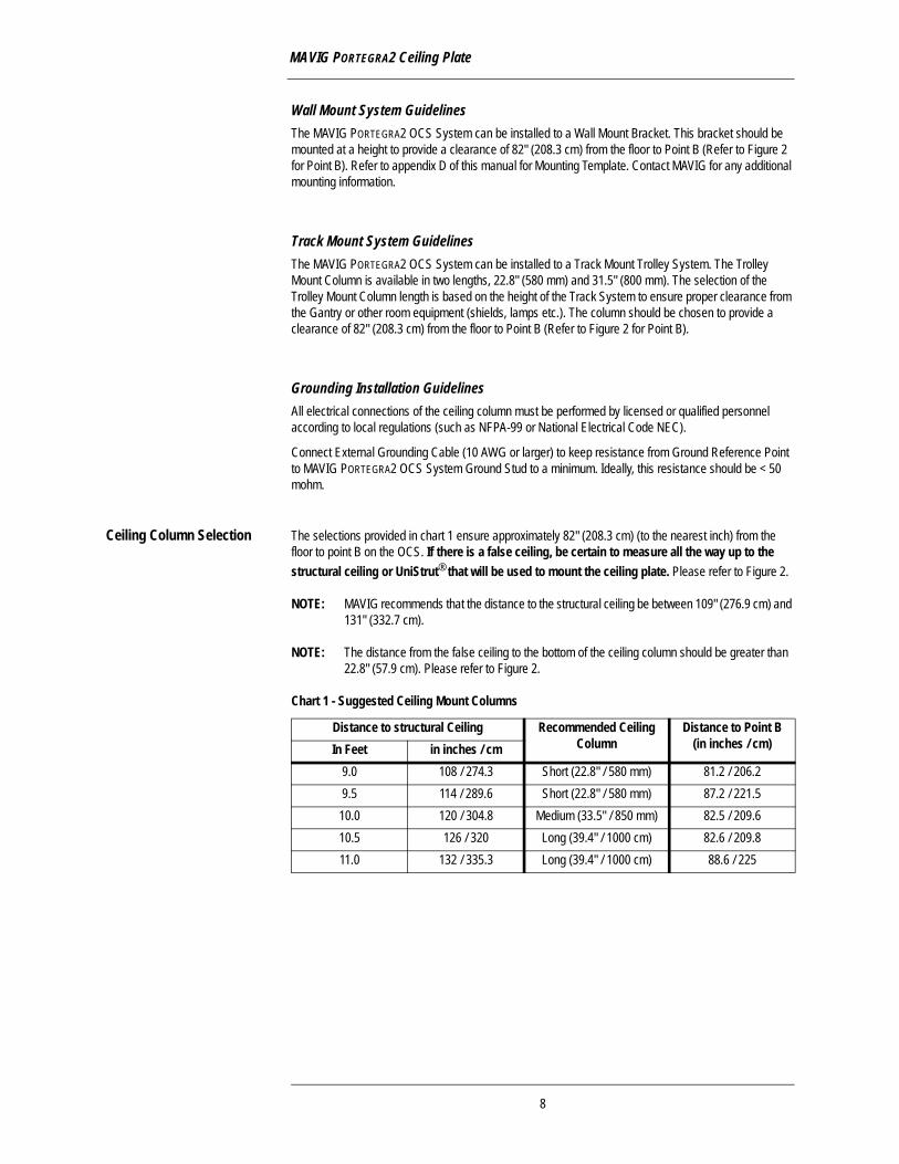
Ceiling Column Selection The selections provided in chart 1 ensure approximately 82" (208.3 cm) (to the nearest inch) from the floor to point B on the OCS. If there is a false ceiling, be certain to measure all the way up to the structural ceiling or UniStrut® that will be used to mount the ceiling plate. Please refer to Figure 2.
NOTE: MAVIG recommends that the distance to the structural ceiling be between 109" (276.9 cm) and 131" (332.7 cm).
NOTE: The distance from the false ceiling to the bottom of the ceiling column should be greater than 22.8" (57.9 cm). Please refer to Figure 2.
Chart 1 - Suggested Ceiling Mount Columns
Distance to structural Ceiling Recommended Ceiling Column
Distance to Point B (in inches / cm)In Feet in inches / cm
9.0 108 / 274.3 Short (22.8" / 580 mm) 81.2 / 206.29.5 114 / 289.6 Short (22.8" / 580 mm) 87.2 / 221.5
10.0 120 / 304.8 Medium (33.5" / 850 mm) 82.5 / 209.610.5 126 / 320 Long (39.4" / 1000 cm) 82.6 / 209.811.0 132 / 335.3 Long (39.4" / 1000 cm) 88.6 / 225
8
3 - Installation
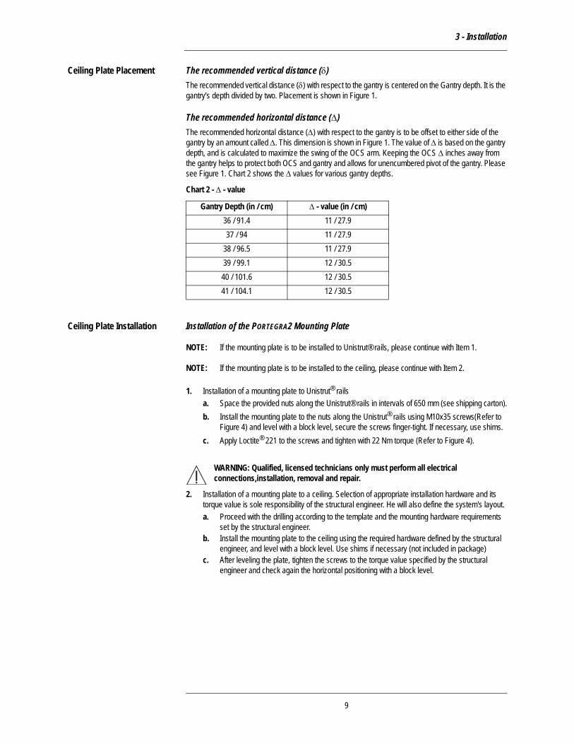
Ceiling Plate Placement The recommended vertical distance (δ)The recommended vertical distance (δ) with respect to the gantry is centered on the Gantry depth. It is the gantry’s depth divided by two. Placement is shown in Figure 1.
The recommended horizontal distance (Δ) The recommended horizontal distance (Δ) with respect to the gantry is to be offset to either side of the gantry by an amount called Δ. This dimension is shown in Figure 1. The value of Δ is based on the gantry depth, and is calculated to maximize the swing of the OCS arm. Keeping the OCS Δ inches away from the gantry helps to protect both OCS and gantry and allows for unencumbered pivot of the gantry. Please see Figure 1. Chart 2 shows the Δ values for various gantry depths.
Chart 2 - Δ - value
Ceiling Plate Installation Installation of the PORTEGRA2 Mounting Plate
NOTE: If the mounting plate is to be installed to Unistrut® rails, please continue with Item 1.
NOTE: If the mounting plate is to be installed to the ceiling, please continue with Item 2.
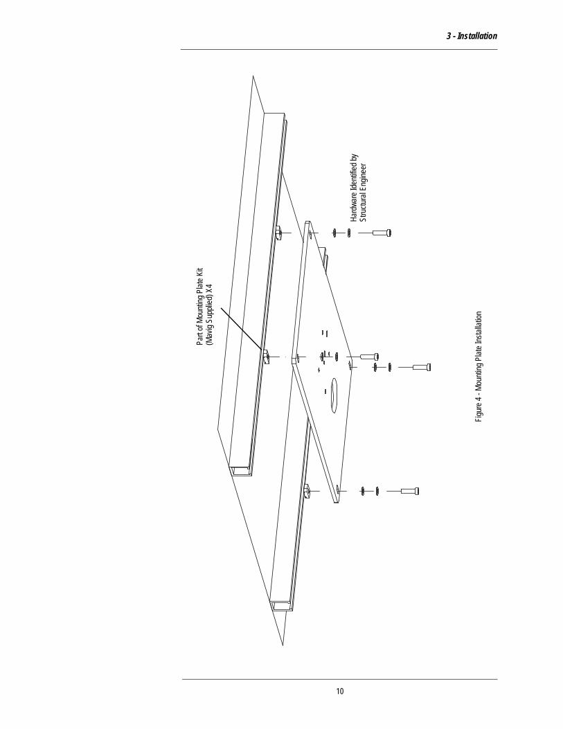
1. Installation of a mounting plate to Unistrut® railsa. Space the provided nuts along the Unistrut® rails in intervals of 650 mm (see shipping carton).b. Install the mounting plate to the nuts along the Unistrut® rails using M10x35 screws(Refer to
Figure 4) and level with a block level, secure the screws finger-tight. If necessary, use shims.c. Apply Loctite® 221 to the screws and tighten with 22 Nm torque (Refer to Figure 4).
WARNING: Qualified, licensed technicians only must perform all electrical connections,installation, removal and repair.
2. Installation of a mounting plate to a ceiling. Selection of appropriate installation hardware and its torque value is sole responsibility of the structural engineer. He will also define the system's layout.a. Proceed with the drilling according to the template and the mounting hardware requirements
set by the structural engineer.b. Install the mounting plate to the ceiling using the required hardware defined by the structural
engineer, and level with a block level. Use shims if necessary (not included in package)c. After leveling the plate, tighten the screws to the torque value specified by the structural
engineer and check again the horizontal positioning with a block level.
Gantry Depth (in / cm) Δ - value (in / cm)36 / 91.4 11 / 27.937 / 94 11 / 27.9
38 / 96.5 11 / 27.939 / 99.1 12 / 30.540 / 101.6 12 / 30.541 / 104.1 12 / 30.5
9
3 - Installation
Figur
e 4 -
Moun
ting P
late I
nstal
lation
Part
of Mo
untin
g Plat
e Kit
Hard
ware
Iden
tified
bySt
ructu
ral E
ngine
er
(Mav
ig Su
pplie
d) X
4
10
Appendix A - Dimensions
Appendix A - Dimensions
NOTE: Always consult with an architect or structural engineer before installation concerning ceiling structure weight limitations
NOTE: Refer to the equipment anchorage and seismic engineering report contained within this document for loading requirements.
NOTE: Once the proper position is located for the Portegra2, the ceiling mounting plate must be installed by a qualified structural engineer.
NOTE: The template in Appendix D shows the bolt hole pattern for the ceiling mount plate.
NOTE: When mounted ensure that the ceiling, mount plate is level or plumb to within +/- 1 degree.
NOTE: Please refer to figure 7 when reviewing the following material:
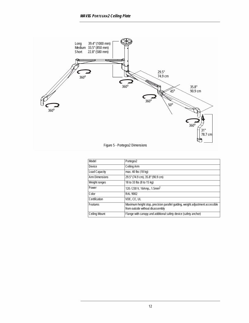
NOTE: The PORTEGRA2 Spring Arm can be moved vertically up and down. The upper stop is adjustable and can be set to allow upward movement between 0O and 45O to Point A. The downward stop is fixed and allows movement down to 50O to Point C. Point B represents the low point of the Horizontal Arm.
NOTE: The ceiling plate may be above the false ceiling. It is important to take measurements from the ceiling plate not the false ceiling.
NOTE: The end user should select the appropriate ceiling column with the knowledge that the vertical arm will hang down approximately 31" (78.7 cm) lower than point B.
• Point B is the lowest point of the Portegra2 system with the horizontal arm extended straight out. It is the joint between the components of the horizontal arm.
11
MAVIG PORTEGRA2 Ceiling Plate
360o
360o
360o
360o
360o
50o
45o
29.5"74.9 cm
35.8"90.9 cm
Long 39.4" (1000 mm)
Short 22.8" (580 mm)Medium 33.5" (850 mm)
31"78.7 cm
Figure 5 - Portegra2 Dimensions
Model Portegra2Device Ceiling ArmLoad Capacity max. 40 lbs (18 kg)Arm Dimensions 29.5" (74.9 cm), 35.8" (90.9 cm)Weight ranges 18 to 33 lbs (8 to 15 kg)Power 120 / 230 V, 16Amp., 1.5mm2
Color RAL 9002Certification VDE, CE, ULFeatures Maximum height stop, precision parallel guiding, weight adjustment accessible
from outside without disassemblyCeiling Mount Flange with canopy and additional safety device (safety anchor)
12
Appendix A - Dimensions
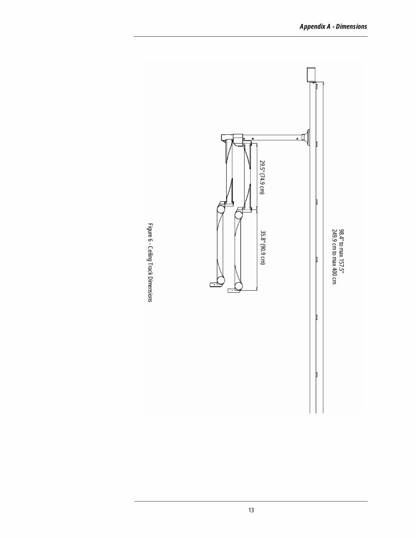
98.4" to max 157.5"249.9 cm to max 400 cm
29.5" (74.9 cm)35.8" (90.9 cm)
Figure 6 - Ceiling Track Dimensions
13

MAVIG PORTEGRA2 Ceiling Plate
Chart 3 - Distance Ranges from the Floor table, shown below, provides distances from the floor to Point A (maximum), Point C and bottom of J-Bow based on the heights to Point B listed in Chart 1. Please refer to Figure 2 and Figure 7. This will allow the customer to gauge how high and low the Spring Arm with J-Bow attached will move with respect to the floor.
Chart 3 - Distances Ranges from the Floor
Distance from Floor to Point B (in / cm) 81.2 / 206.2
87.2 / 221.5
82.5 / 209.6
82.6 / 209.8
88.6 / 225
Distance from Floor to Point A (in / cm) 108 / 274.3
114 / 289.6
109.3 / 277.6
109.4 / 277.9
115.4 / 293.1
Distance from Floor to Point C (in / cm) 55.3 / 140.2
61.3 / 155.7
56.6 / 143.8
56.7 / 144.0
62.7 / 159.3
Minimum Distance from Floor to Bottom of J-Bow (in / cm)
24.3 / 61.5
30.3 / 77.0
25.6 / 65.1
25.7 / 65.3
31.7 / 80.6
Figure 7 - Portegra2 Movement
A
C
B
50o
45o
14
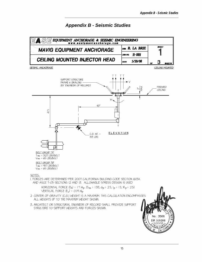
Appendix B - Seismic Studies
Appendix B - Seismic Studies
15
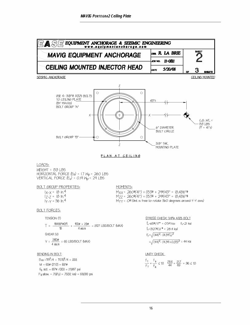
MAVIG PORTEGRA2 Ceiling Plate
16
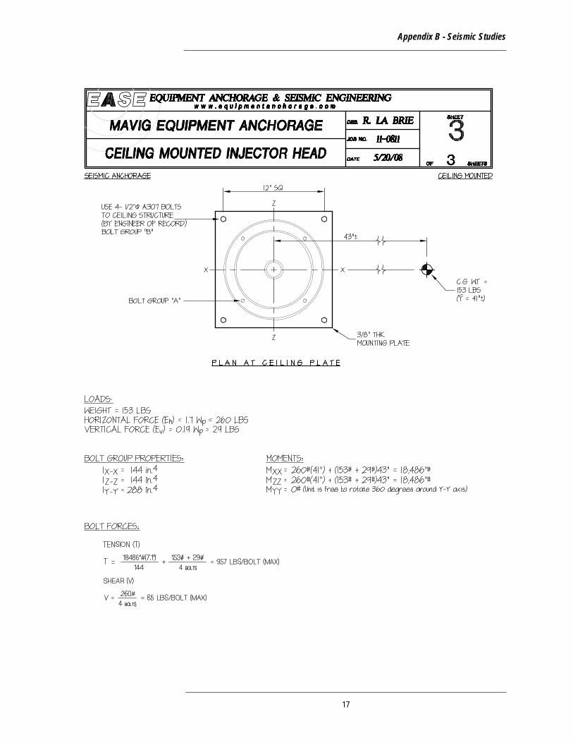
Appendix B - Seismic Studies
17
MAVIG PORTEGRA2 Ceiling Plate
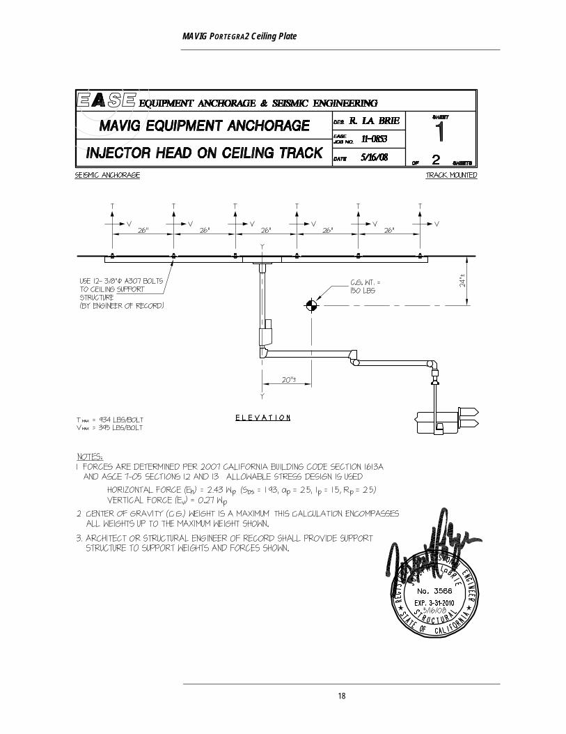
18
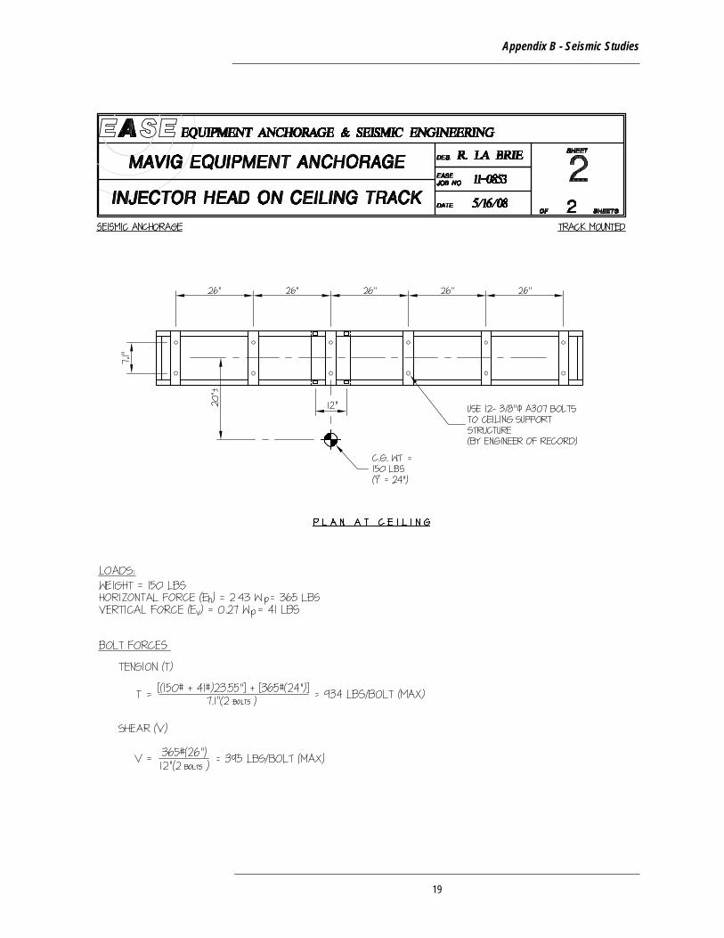
Appendix B - Seismic Studies
19

Appendix B - Seismic Studies
20
Appendix C - Calculations
Appendix C - Calculations
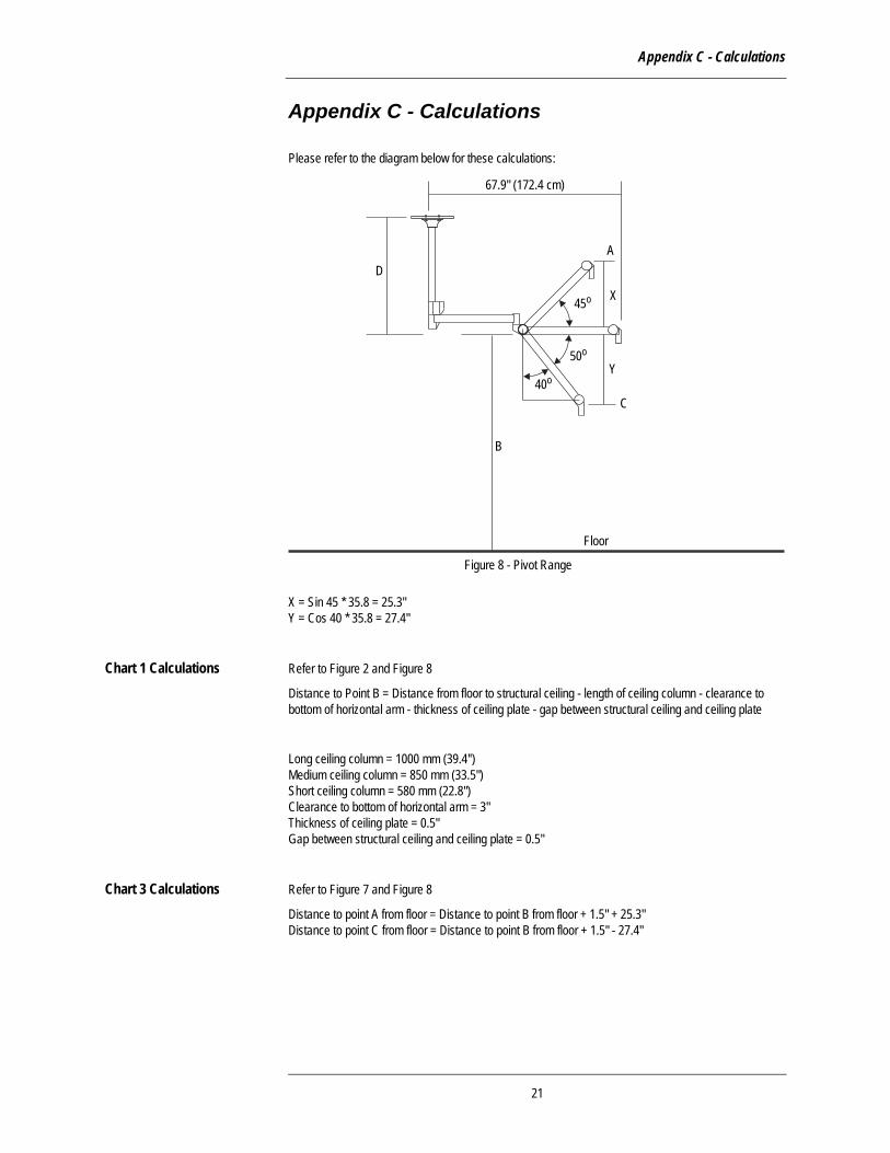
Please refer to the diagram below for these calculations:
X = Sin 45 * 35.8 = 25.3" Y = Cos 40 * 35.8 = 27.4"
Chart 1 Calculations Refer to Figure 2 and Figure 8
Distance to Point B = Distance from floor to structural ceiling - length of ceiling column - clearance to bottom of horizontal arm - thickness of ceiling plate - gap between structural ceiling and ceiling plate
Long ceiling column = 1000 mm (39.4'') Medium ceiling column = 850 mm (33.5") Short ceiling column = 580 mm (22.8") Clearance to bottom of horizontal arm = 3" Thickness of ceiling plate = 0.5" Gap between structural ceiling and ceiling plate = 0.5"
Chart 3 Calculations Refer to Figure 7 and Figure 8
Distance to point A from floor = Distance to point B from floor + 1.5" + 25.3" Distance to point C from floor = Distance to point B from floor + 1.5" - 27.4"
Y
C
A
X
67.9" (172.4 cm)
B
D
40o
50o
45o
Floor
Figure 8 - Pivot Range
21
MAVIG PORTEGRA2 Ceiling Plate
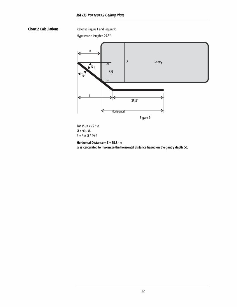
Chart 2 Calculations Refer to Figure 1 and Figure 9:
Hypotenuse length = 29.5"
Tan Ø1 = x / 2 * Δ Ø = 90 - Ø1 Z = Sin Ø * 29.5
Horizontal Distance = Z + 35.8 - Δ Δ is calculated to maximize the horizontal distance based on the gantry depth (x).
35.8"
Horizontal
Z
X Gantry
X/2
Δ
Ø
Ø1
Figure 9
22
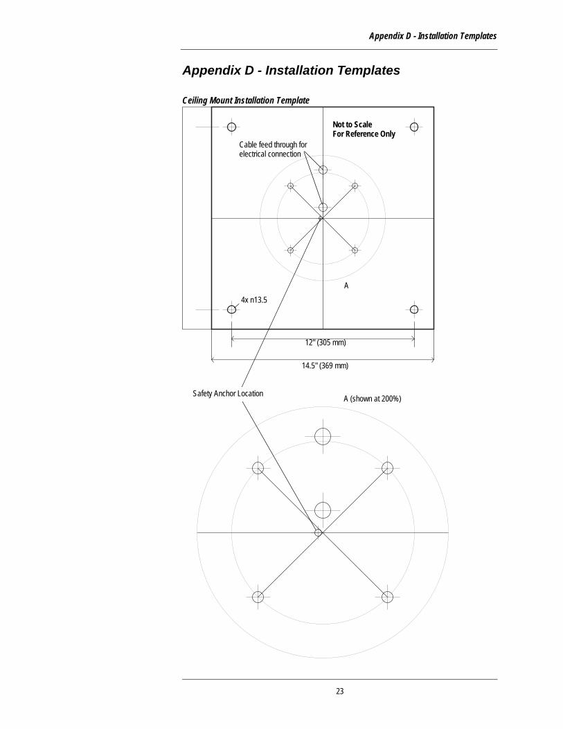
Appendix D - Installation Templates
Appendix D - Installation Templates
Ceiling Mount Installation Template
Safety Anchor Location
14.5" (369 mm)
12" (305 mm)
4x n13.5
Cable feed through forelectrical connection
A
A (shown at 200%)
Not to ScaleFor Reference Only
23
MAVIG PORTEGRA2 Ceiling Plate
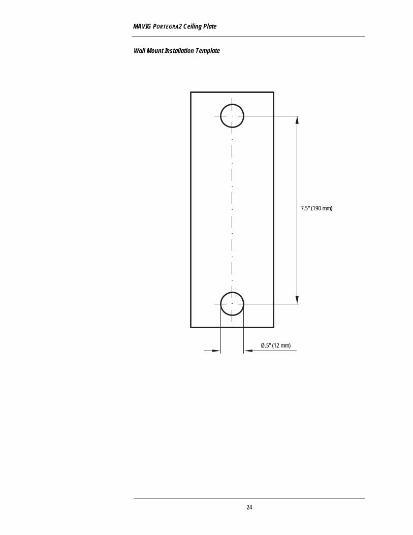
Wall Mount Installation Template
7.5" (190 mm)
Ø.5" (12 mm)
24

59
60
MAVIG GmbHHeadquartersStahlgruberring 581829 MunichGermany
PO Box 82036281803 Munich(: +49 89 42096 0Fax: +49 89 42096 200E-mail: [email protected]
MAVIG B.V.
(: +31 70 345 99 85Fax: +31 70 360 45 42E-mail: [email protected]
MAVIG France, SAS
(/Fax: +33 1 30 59 46 23Mobile: +33 6 70 16 63 67E-mail: [email protected]
Ti-Ba Enterprises, Inc.MAVIG Representation in North America
(: +1 585 247 1212Fax: +1 585 247 1395E-mail: [email protected]
www.mavig.com© Copyright 2009MAVIG GmbH, Munich, Germany
Subject to technical alterations!0309-XDME / Printed in Germany