CEE 498C AutoCAD Graphics Communication for Civil and Environmental Engineers Introduction to the...
19
Graphics Communication for Civil and Environmental Engineers Introduction to the class and the software Chapter 1
-
Upload
brandon-douglas -
Category
Documents
-
view
249 -
download
0
Transcript of CEE 498C AutoCAD Graphics Communication for Civil and Environmental Engineers Introduction to the...

CEE 498C AutoCAD
Graphics Communication for Civil and Environmental Engineers
Introduction to the class and the softwareChapter 1
Goals
1. Provide students with AutoCAD skills and knowledge of graphics communication for CEE projects so that they are able to create drawings, in an efficient manner, that convey, with a high level of clarity and with sufficient detail, a CEE design to their colleagues.
Goals
2. Provide students with the skills to use modern computing tools to facilitate the engineering design process
3. Teach the students basic concepts of requirements for design and computations of CEE projects
4. Familiarize the students with CAD applications in various CEE fields
Class Format - Lectures•About half the lecture on Mondays•Discuss basic elements of CEE drawings,
techniques for creating 2D drawings of 3D structures, organization of drawing packages, etc. •Discuss fundamental ideas of CAE and
use of CAE in design in certain CEE applications such as hydrology, roads, structural drawings.

Class Format - lectures•Answer questions about skills learned in
the lab•Provide a very brief discussion of the
upcoming lab - what can you do to prepare for the lab• Explore related topics such as
standards, drawing sets, flood planes, drainage basins, contours, etc.• Explore BIM concepts and 3D drawings

Class Format - labs
•About half the session on Mondays and 1.5 hours on Wednesday • Learn AutoCAD skills• Independent Study – about 3 hrs. per
week• Practice AutoCAD skills• Practice creating a design and communicating
it using 2D drawings
Class Outline & Conduct• Schedule•Note midterm exams, missed classes•Homework•Note when a hard and/or a soft copy
of the answers are required• Late homework?•Grading policy
Software•We will start with Autodesk AutoCAD 2013,
for Windows• AutoCAD is available for Mac, but it lacks
some features of the Windows version. For more details , visit:
http://www.autodesk.com , support, AutoCAD for Mac.• This class will use Autodesk AutoCAD 2013.
You can download it for free as a student from: http://students.autodesk.com• The software is also available in More Hall
computer alb

Help ...
o Kamal Ahmed([email protected])• 121 c More Hall• Office hrs: Mon., 2:10 3:00• Class website:http://depts.washington.edu/ceecad
Technical Drawings and CAD
• Drawings (drafting) Is a drawing technique that creates accurate representations of objects in engineering and Science• Graphic Communication is a method of
communication using technical drawings• Computer Aided Design (CAD) is the
creation of technical drawings using software.
Drawing Standards (ISO and ANSI)• ISO: International Standard Organization• International System of Units,
abbreviated SI (System Internationale)•Metric standards (meter, cm, mm, etc.)• ANSI: American National Standard Institute
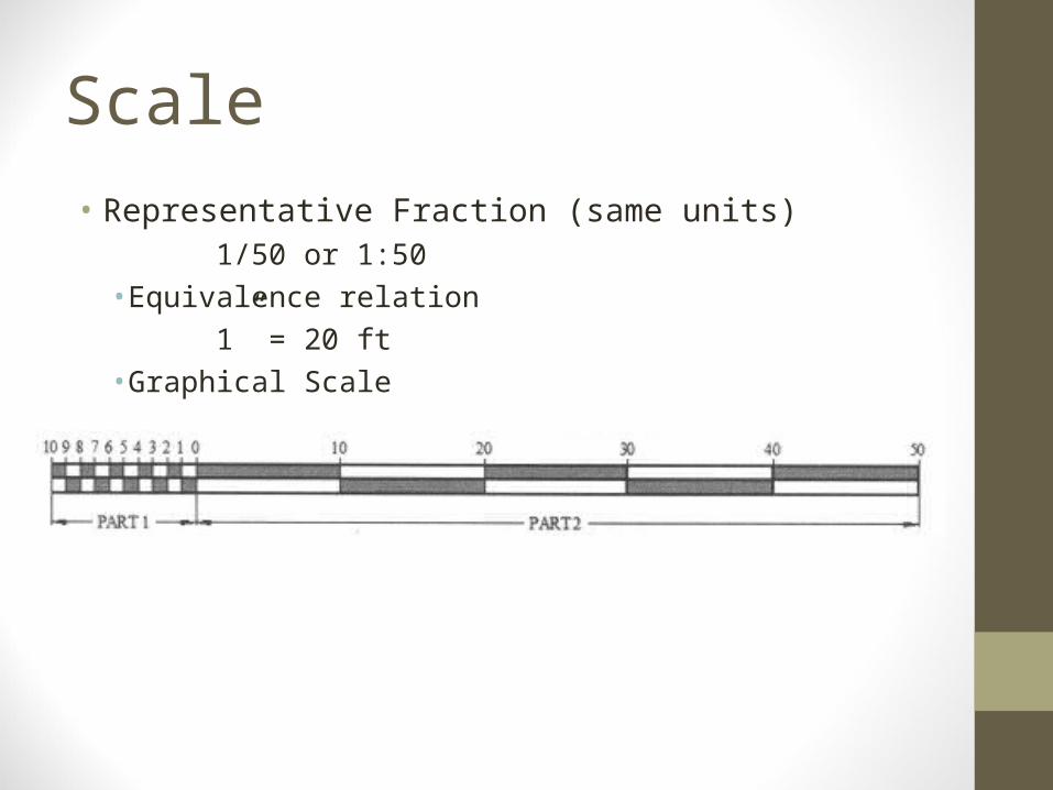
Scale• Representative Fraction (same units)
1/50 or 1:50•Equivalence relation
1” = 20 ft•Graphical Scale
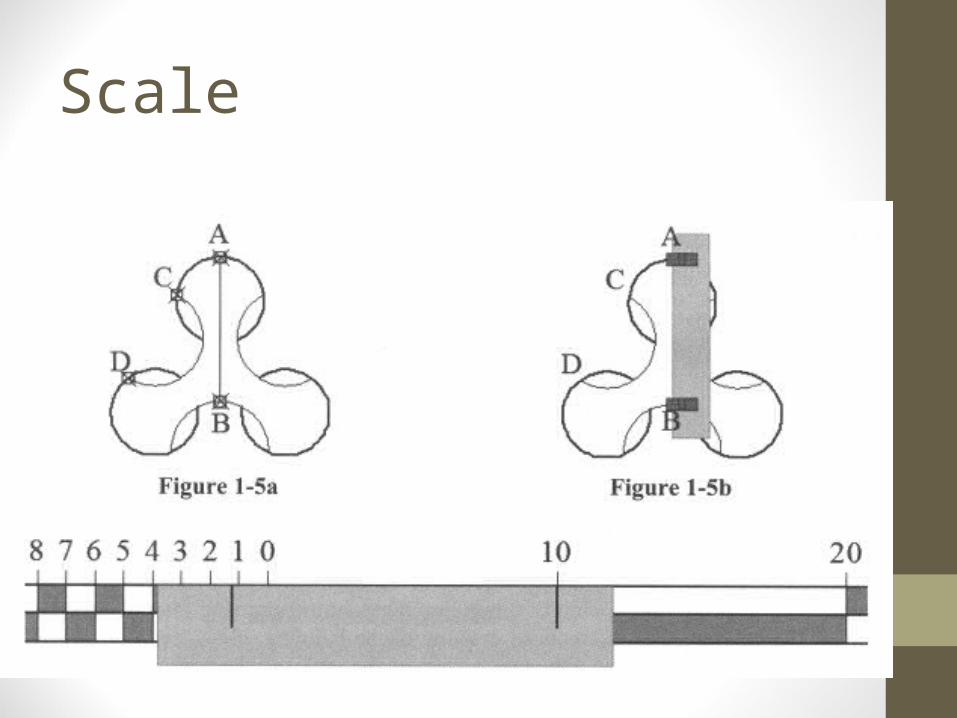
Scale
Full, Large, and Small Scales• Full Scale: objects are drawn 1:1 scale• Small Scale: Objects appear on a drawing
“smaller” than reality:1:100, 1”= 15’•Large Scale: Objects appear on a drawing “Larger” than reality•NOTE THAT SURVEYORS WILL HAVE A DIFFERENT INTERPRETATION OF SMALL AND LARGE SCALES
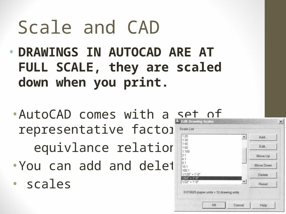
Scale and CAD• DRAWINGS IN AUTOCAD ARE AT FULL
SCALE, they are scaled down when you print.
• AutoCAD comes with a set of representative factors and
equivlance relations scales• You can add and delete new• scales
• We will move to the lab in More Hall for hands-on practice• Few remarks:• Almost any command in AutoCAD can be done in
several ways• Try to get used to type the commands and memorize
the shortcut much as you can. It is easier for example to type “L” to draw a line than to click on an icon or select from a drop down menu. Shorcuts are in the resources • Section of the website
INTRODUCTION TO THE SOFTWARE
• There are some tricks to make your work more efficient, such as:• Shift + right click on the screen, will give you an option
to draw from a point half way between two other points that are not connected. That is easier than drawing a line between them and snap to its middle• While in that mode, if you select to snap to the middle
of a line for example, you will snap only to middle of lines, handy in busy drawings• “tk” command, while executing another command and
expecting a point, will let you navigate to a point by visiting other points, reduces construction lines.
INTRODUCTION TO THE SOFTWARE
• Control +1 will bring up properties pallet of a selected object such as a circle. You can view and verify the properties of the object, but you can also modify the object this way.• If you want to print a drawing but X and Y, or N and E, are
not along the long and short sides of the paper, you may need to rotate the drawing so that the Y or N is tilted WRT to the paper, type UCS, rotate the X and Y, and type: plan to rotate the map so that the UCS Y axis is up. That will rotate the drawing. Bring back the CS to the way it was by clicking on the arrow under the navigation wheel and select WCS
INTRODUCTION TO THE SOFTWARE
•When you know more about the software, remember to plan ahead, before you draw:• Determine your units• Decide on a scale and paper size• Setup your styles: text, dimensions, tables, etc.• Difference between classic and drafting & annotation in
AutoCAD, which is better??
INTRODUCTION TO THE SOFTWARE