CECE: A Deep Throttling Demonstrator Cryogenic Engine for ... · CECE: A Deep Throttling...
8
CECE: A Deep Throttling Demonstrator Cryogenic Engine for NASA's Lunar Lander Victor J. Giuliano' Jimothy G. Leonard, and Walter M. Adamski3 Pratt & Whitney Rocketdyne, West Palm Beach, FL 33410 and Tony S. Kim4 NASA Marshall Space Flight Center, Huntsville, AL 35812 As one of the first technology development programs awarded under NASA's Vision for Space Exploration, the Pratt & Whitney Rocketdyne (PWR) Deep Throttling, Common Extensible Cryogenic Engine (CECE) program was selected by NASA in November 2004 to begin technology development and demonstration toward a deep throttling, cryogenic Lunar Lander engine for use across multiple human and robotic lunar exploration mission segments with extensibility to Mars. The CECE program leverages the maturity and previous investment of a flight-proven hydrogen/oxygen expander cycle engine, the RL10, to develop and demonstrate an unprecedented combination of reliability, safety, durability, throttlability, and restart capabilities in a high-energy, cryogenic engine. NASA Marshall Space Flight Center and NASA Glenn Research Center personnel were integral design and analysis team members throughout the requirements assessment, propellant studies and the deep throttling demonstrator elements of the program. The testbed selected for the initial deep throttling demonstration phase of this program was a minimally modified RL10 engine, allowing for maximum current production engine commonality and extensibility with minimum program cost. In just nine months from technical program start, CECE Demonstrator No. 1 engine testing in April/May 2006 at PWR's E06 test stand successfully demonstrated in excess of 10:1 throttling of the hydrogen/oxygen expander cycle engine. This test provided an early demonstration of a viable, enabling cryogenic propulsion concept with invaluable system-level technology data acquisition toward design and development risk mitigation for both the subsequent CECE Demonstrator No. 2 program and to the future Lunar Lander Design, Development, Test and Evaluation effort. This paper describes the characteristics of the program and the engine design features, as well as component manufacturing efforts, test facility modifications and test results. ' Program Manager, Constellation Programs, P.O. Box 109600, M/S 710-99, Senior Member 2 Chief Engineer, Constellation Programs, P.O. Box 109600, M/S 710-99 s Manager, Propulsion Systems Analysis and Integration, P.O. Box 109600, M/S 712-67 4, Lox Hydrogen Deep Throttling Engine (DTE) Advanced Capability Development Project Manager, Science & Mission Systems Office, Exploration Advanced Capabilities Development Office, NASA/MSFC/VP33, Member American Institute of Aeronautics and Astronautics https://ntrs.nasa.gov/search.jsp?R=20090028814 2018-09-01T02:45:53+00:00Z
Transcript of CECE: A Deep Throttling Demonstrator Cryogenic Engine for ... · CECE: A Deep Throttling...
CECE: A Deep Throttling Demonstrator Cryogenic Enginefor NASA's Lunar Lander
Victor J. Giuliano' Jimothy G. Leonard, and Walter M. Adamski3Pratt & Whitney Rocketdyne, West Palm Beach, FL 33410
and
Tony S. Kim4NASA Marshall Space Flight Center, Huntsville, AL 35812
As one of the first technology development programs awarded under NASA's Vision forSpace Exploration, the Pratt & Whitney Rocketdyne (PWR) Deep Throttling, CommonExtensible Cryogenic Engine (CECE) program was selected by NASA in November 2004 tobegin technology development and demonstration toward a deep throttling, cryogenic LunarLander engine for use across multiple human and robotic lunar exploration missionsegments with extensibility to Mars. The CECE program leverages the maturity andprevious investment of a flight-proven hydrogen/oxygen expander cycle engine, the RL10, todevelop and demonstrate an unprecedented combination of reliability, safety, durability,throttlability, and restart capabilities in a high-energy, cryogenic engine. NASA MarshallSpace Flight Center and NASA Glenn Research Center personnel were integral design andanalysis team members throughout the requirements assessment, propellant studies and thedeep throttling demonstrator elements of the program. The testbed selected for the initialdeep throttling demonstration phase of this program was a minimally modified RL10 engine,allowing for maximum current production engine commonality and extensibility withminimum program cost. In just nine months from technical program start, CECEDemonstrator No. 1 engine testing in April/May 2006 at PWR's E06 test stand successfullydemonstrated in excess of 10:1 throttling of the hydrogen/oxygen expander cycle engine.This test provided an early demonstration of a viable, enabling cryogenic propulsion conceptwith invaluable system-level technology data acquisition toward design and developmentrisk mitigation for both the subsequent CECE Demonstrator No. 2 program and to thefuture Lunar Lander Design, Development, Test and Evaluation effort.
This paper describes the characteristics of the program and the engine design features, aswell as component manufacturing efforts, test facility modifications and test results.
' Program Manager, Constellation Programs, P.O. Box 109600, M/S 710-99, Senior Member2 Chief Engineer, Constellation Programs, P.O. Box 109600, M/S 710-99s Manager, Propulsion Systems Analysis and Integration, P.O. Box 109600, M/S 712-674, Lox Hydrogen Deep Throttling Engine (DTE) Advanced Capability Development Project Manager, Science &Mission Systems Office, Exploration Advanced Capabilities Development Office, NASA/MSFC/VP33, Member
American Institute of Aeronautics and Astronautics
https://ntrs.nasa.gov/search.jsp?R=20090028814 2018-09-01T02:45:53+00:00Z
I. IntroductionThe main goal of the CECE program is to leverage the maturity and previous investment of a flight-proven
expander cycle engine to develop and demonstrate technology advancement toward an unprecedented combinationof extended reliability, safety, throttlability, and restart capabilities in a high-energy, cryogenic engine.
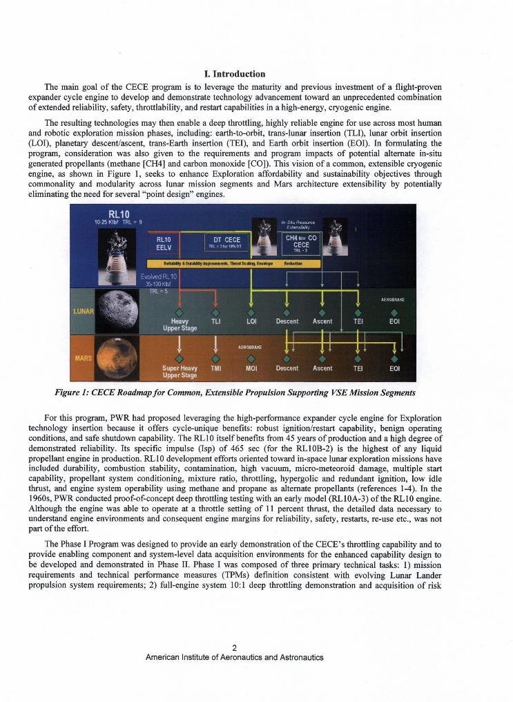
The resulting technologies may then enable a deep throttling, highly reliable engine for use across most humanand robotic exploration mission phases, including: earth-to-orbit, trans-lunar insertion (TLI), lunar orbit insertion(LOI), planetary descent/ascent, trans-Earth insertion (TEI), and Earth orbit insertion (EOI). In formulating theprogram, consideration was also given to the requirements and program impacts of potential alternate in-situgenerated propellants (methane [CH4] and carbon monoxide [CO]). This vision of a common, extensible cryogenicengine, as shown in Figure 1, seeks to enhance Exploration affordability and sustainability objectives throughcommonality and modularity across lunar mission segments and Mars architecture extensibility by potentiallyeliminating the need for several "point design" engines.
Figure 1: CECE Roadmap for Common, Extensible Propulsion Supporting VSE Mission Segments
For this program, PWR had proposed leveraging the high-performance expander cycle engine for Explorationtechnology insertion because it offers cycle-unique benefits: robust ignition/restart capability, benign operatingconditions, and safe shutdown capability. The RL 10 itself benefits from 45 years of production and a high degree ofdemonstrated reliability. Its specific impulse (Isp) of 465 sec (for the RL10B-2) is the highest of any liquidpropellant engine in production. RL10 development efforts oriented toward in-space lunar exploration missions haveincluded durability, combustion stability, contamination, high vacuum, micro-meteoroid damage, multiple startcapability, propellant system conditioning, mixture ratio, throttling, hypergolic and redundant ignition, low idlethrust, and engine system operability using methane and propane as alternate propellants (references 1-4). In the1960s, PWR conducted proof-of-concept deep throttling testing with an early model (RL10A-3) of the RL10 engine.Although the engine was able to operate at a throttle setting of 11 percent thrust, the detailed data necessary tounderstand engine environments and consequent engine margins for reliability, safety, restarts, re-use etc., was notpart of the effort.
The Phase I Program was designed to provide an early demonstration of the CECE's throttling capability and toprovide enabling component and system-level data acquisition environments for the enhanced capability design tobe developed and demonstrated in Phase II. Phase I was composed of three primary technical tasks: 1) missionrequirements and technical performance measures (TPMs) definition consistent with evolving Lunar Landerpropulsion system requirements; 2) full-engine system 10:1 deep throttling demonstration and acquisition of risk
2American Institute of Aeronautics and Astronautics
reduction-enabling performance data through the Demo I engine test; and 3) conceptual design of a CECEDemonstrator No. 2 configuration toward further risk reduction design and demonstration efforts under Phase II,including preliminary evaluation of methane and carbon-monoxide as alternate propellants. At the conclusion of theprogram, an engine based on technologies developed and demonstrated during the CECE program would be ready toenter Design, Development, Test and Evaluation (DDT&E).
The remainder of this paper addresses activities and results achieved under the second technical task (CECEDeep Throttling Demonstrator No. 1 Engine Test), including component and engine design features andmanufacturing efforts, test facility modifications and overall results.
II. CECE Engine ConfigurationThe CECE Demonstrator No.l Engine was assembled from a mix of heritage RL10 development hardware,
valves from different programs, and specially made parts needed to meet configuration and performance needs. Allof the heritage RL10 development hardware, all of the valves, and all of the assembly manpower to assemble theengine were provided by PWR at no charge to the contract.
Demo 1 was designed to provide the critical empirical engine data necessary to address future operation issuesassociated with up to a 20:1 throttling range. System-level issues directly impacting the Demo 1 system hardwaredesign included: sufficient control authority to enable system operation to 10 percent thrust, system stability duringall throttle points, adequate coolant flow at all conditions, robust ignition, thrust chamber heat flux at all conditions,and the minimum allowable LOX-side injector pressure drop during low throttle points. Hardware changesaddressing these issues consisted of a valve suite selection that added the necessary system control flexibility andmodifications to critical injector features. Descriptions of these hardware changes are presented over the next severalparagraphs.
A. Valves
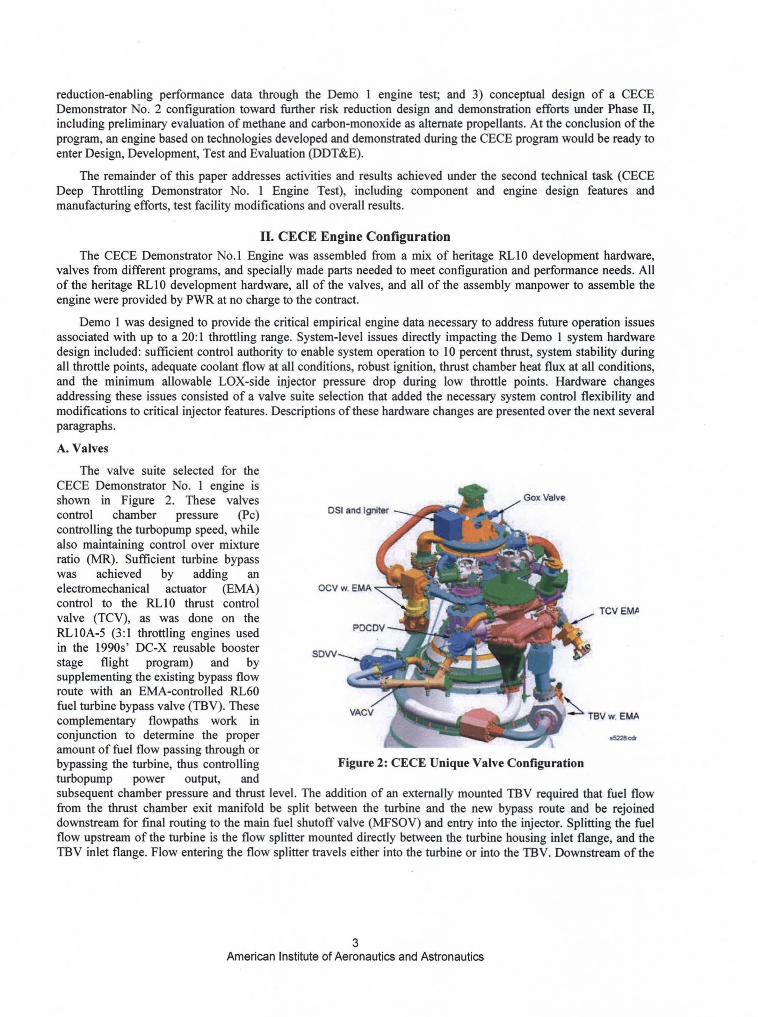
The valve suite selected for theCECE Demonstrator No. 1 engine isshown in Figure 2. These valves Gox Valve
control chamber pressure (Pc) Dsl and Igniter
controlling the turbopump speed, whilealso maintaining control over mixtureratio (MR). Sufficient turbine bypasswas achieved by adding anelectromechanical actuator (EMA) OCV w EMA
control to the RL10 thrust control
a TCV EMAvalve (TCV), as was done on the °^ lRLIOA-5 (3:1 throttling engines used PDCDV +
in the 1990s' DC-X reusable boosterSDVV
stage flight program) and bysupplementing the existing bypass flowroute with an EMA-controlled RL60fuel turbine bypass valve (TBV). Thesecomplementary flowpaths work in
vACV TBV w EMA
conjunction to determine the properamount of fuel flow passing through orbypassing the turbine, thus controlling Figure 2: CECE Unique Valve Configurationturbopump power output, andsubsequent chamber pressure and thrust level. The addition of an externally mounted TBV required that fuel flowfrom the thrust chamber exit manifold be split between the turbine and the new bypass route and be rejoineddownstream for final routing to the main fuel shutoff valve (MFSOV) and entry into the injector. Splitting the fuelflow upstream of the turbine is the flow splitter mounted directly between the turbine housing inlet flange, and theTBV inlet flange. Flow entering the flow splitter travels either into the turbine or into the TBV. Downstream of the
American Institute of Aeronautics and Astronautics
turbine and TBV, the flowpaths rejoin at the flow uniter before continuing on to the MFSOV. The proposedmanifold route was also approved following a system structural analysis.
Ten separate large line external manifold assemblies and detail flowpath parts were designed specifically foruse on Demo 1. Each manifold was configured as closely as possible to analogous RL10 hardware, and wereproduced by the RL10 production external tube supplier. In other words, materials, flange configurations, boltpatterns, manufacturing processes, proof pressure testing, and quality inspections were maintained from analogoushardware, if such hardware existed. Where no analogous hardware existed, RL10 production hardware margins andStandard Work methods were employed to assure that the CECE designs met, or exceeded, RL10 productionmargins. In some cases, the final configuration differed from the original design intent to take advantage ofsalvageable material on hand, to address manufacturing errors, or due to unavailability of some design-intent seals.
B. Injector/Chamber
The RL10 injector was redesigned for CECE while maintaining as much commonality with the current RL10basic injector assembly as possible. The CECE cycle data were used to modify the injector with the principlechanges being a reduction of the liquid oxygen flow area. In addition to changing the injector element flow areas,the outer row mixture ratio was reduced. This provided added thermal margin for the chamber and guarded against
,test program uncertainties.
The CECE cycle was designed to demonstrate 10:1 throttling across a fixed geometry injector. However, since a10:1 throttle ratio implies a high LOX pressure drop ratio, high pressure drops at 100 percent and low pressure dropsat 10 percent were tolerated in the design.
Since the fuel effective flow area was similar to that of the base RL10 engine, the fuel areas needed littlemodification. The main modification to the injector flow area was to the LOX flow area.
The chamber pressures and higher than heritage LOX injector pressure drops for the cycle operation of CECErequired a structural analysis to be conducted on the injector to ensure operation within safe margins. The structuralanalysis showed stresses were less than those experienced by the injectors on previous RL10 engines and providedsufficient margin.
The final task addressing injector operation was a heat transfer analysis of the CECE injector face transpirationcooling. The faceplate'' material used for the CECE injector is the same used on the RL10A-4 and RL10B-2 engines.Therefore, the adequacy of the transpiration cooling was assessed for the CECE operating conditions and was foundto be adequate.
The CECE combustion chamber was based on a Bill-of-Material A-4 chamber. The thermal loading of theCECE chamber was evaluated at all power levels to ensure chamber health throughout the range of operation.Chamber wall temperature profiles were evaluated at 100 percent, 80 percent, 60 percent, 40 percent, 20 percent,and 10 percent power conditions. It was determined that the wall temperatures would remain lower than those on theRL 10A-4 engines throughout the entire range of operation. However, as previously discussed, the outer row mixtureratio was reduced and this added to the predicted chamber thermal margins.
The coolant distribution inside of the CECE dual exit coolant manifold was modeled to assess the uniformity ofthe coolant and to determine the minimum tube coolant flow rate used in the aforementioned tube hot-walltemperature analysis. These data were used to calculate the hot-wall temperature at off-nominal conditions to assessthe maximum thermal loading on the combustion chamber wall. The analysis, indicated that the minimum tubecoolant flow rate for the cycle occurs at the 100 percent throttle point and is 97 percent of the average tube coolantflow rate. Due to the decrease in pressure loss in the coolant exit manifold as the engine is throttled down, thecoolant distribution becomes more evenly distributed as the thrust is decreased. Therefore, the 100 percent conditionproduces the most extreme coolant non-uniform distribution during operation. It was determined that the coolantdistribution provided by the chamber was sufficient to avoid excessive thermal loads within the combustion chamberwall under steady-state operation at all operating conditions.
American Institute of Aeronautics and Astronautics
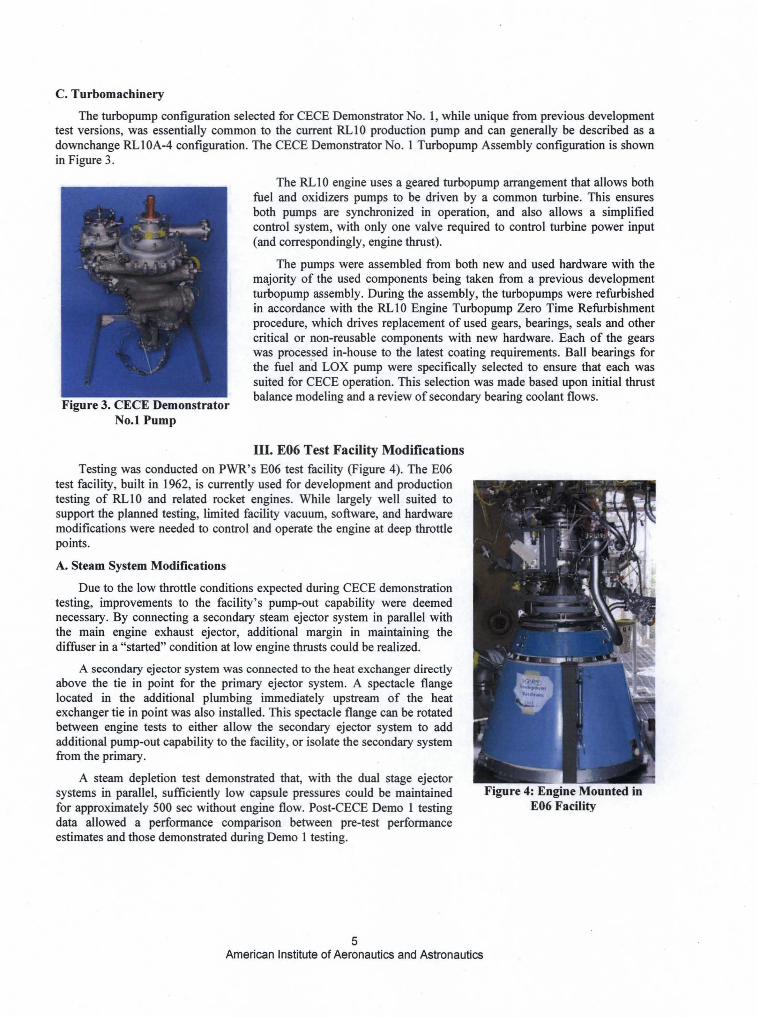
Figure 3. CECE DemonstratorNo.1 Pump
Figure 4: Engine Mounted inE06 Facility
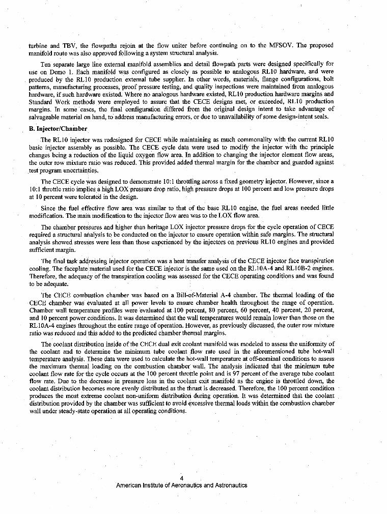
C. Turbomachinery
The turbopump configuration selected for CECE Demonstrator No. 1, while unique from previous developmenttest versions, was essentially common to the current RL10 production pump and can generally be described as adownchange RL 10A-4 configuration. The CECE Demonstrator No. 1 Turbopump Assembly configuration is shownin Figure 3.
The RL10 engine uses a geared turbopump arrangement that allows bothfuel and oxidizers pumps to be driven by a common turbine. This ensuresboth pumps are synchronized in operation, and also allows a simplifiedcontrol system, with only one valve required to control turbine power input(and correspondingly, engine thrust).
The pumps were assembled from both new and used hardware with themajority of the used components being taken from a previous developmentturbopump assembly. During the assembly, the turbopumps were refurbishedin accordance with the RL10 Engine Turbopump Zero Time Refurbishmentprocedure, which drives replacement of used gears, bearings, seals and othercritical or non-reusable components with new hardware. Each of the gearswas processed in-house to the latest coating requirements. Ball bearings forthe fuel and LOX pump were specifically selected to ensure that each wassuited for CECE operation. This selection was made based upon initial thrustbalance modeling and a review of secondary bearing coolant flows.
III. E06 Test Facility ModificationsTesting was conducted on PWR's E06 test facility (Figure 4). The E06
test facility, built in 1962, is currently used for development and productiontesting of RL10 and related rocket engines. While largely well suited tosupport the planned testing, limited facility vacuum, software, and hardwaremodifications were needed to control and operate the engine at deep throttlepoints.
A. Steam System Modifications
Due to the low throttle conditions expected during CECE demonstrationtesting, improvements to the facility's pump-out capability were deemednecessary. By connecting a secondary steam ejector system in parallel withthe main engine exhaust ejector, additional margin in maintaining thediffuser in a "started" condition at low engine thrusts could be realized.
A secondary ejector system was connected to the heat exchanger directlyabove the tie in point for the primary ejector system. A spectacle flangelocated in the additional plumbing immediately upstream of the heatexchanger tie in point was also installed. This spectacle flange can be rotatedbetween engine tests to either allow the secondary ejector system to addadditional pump-out capability to the facility, or isolate the secondary systemfrom the primary.
A steam depletion test demonstrated that, with the dual stage ejectorsystems in parallel, sufficiently low capsule pressures could be maintainedfor approximately 500 sec without engine flow. Post-CECE Demo 1 testingdata allowed a performance comparison between pre-test performanceestimates and those demonstrated during Demo 1 testing.
American Institute of Aeronautics and Astronautics
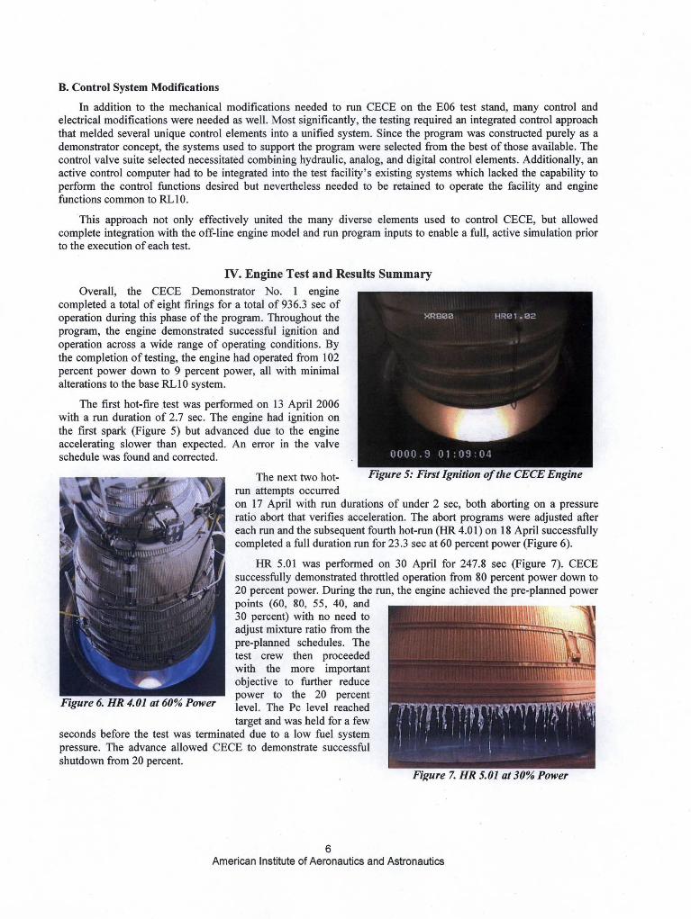
Figure 5: First Ignition of the CECE Engine
Figure 7. HR 5.01 at 30% Power
B. Control System Modifications
In addition to the mechanical modifications needed to run CECE on the E06 test stand, many control andelectrical modifications were needed as well. Most significantly, the testing required an integrated control approachthat melded several unique control elements into a unified system. Since the program was constructed purely as ademonstrator concept, the systems used to support the program were selected from the best of those available. Thecontrol valve suite selected necessitated combining hydraulic, analog, and digital control elements. Additionally, anactive control computer had to be integrated into the test facility's existing systems which lacked the capability toperform the control functions desired but nevertheless needed to be retained to operate the facility and enginefunctions common to RL 10.
This approach not only effectively united the many diverse elements used to control CECE, but allowedcomplete integration with the off-line engine model and run program inputs to enable a full, active simulation priorto the execution of each test.
IV. Engine Test and Results Summary
Overall, the CECE Demonstrator No. 1 enginecompleted a total of eight firings for a total of 936.3 sec ofoperation during this phase of the program. Throughout theprogram, the engine demonstrated successful ignition andoperation across a wide range of operating conditions. Bythe completion of testing, the engine had operated from 102percent power down to 9 percent power, all with minimalalterations to the base RL10 system.
The first hot-fire test was performed on 13 April 2006with a run duration of 2.7 sec. The engine had ignition onthe first spark (Figure 5) but advanced due to the engineaccelerating slower than expected. An error in the valveschedule was found and corrected.
The next two hot-run attempts occurredon 17 April with run durations of under 2 sec, both aborting on a pressureratio abort that verifies acceleration. The abort programs were adjusted aftereach run and the subsequent fourth hot-run (HR 4.01) on 18 April successfullycompleted a full duration run for 23.3 sec at 60 percent power (Figure 6).
HR 5.01 was performed on 30 April for 247.8 sec (Figure 7). CECEsuccessfully demonstrated throttled operation from 80 percent power down to20 percent power. During the run, the engine achieved the pre-planned powerpoints (60, 80, 55, 40, and 130 percent) with no need to ^. 1adjust mixture ratio from thepre-planned schedules. Thetest crew then proceededwith the more importantobjective to further reducepower to the 20 percent
Figure 6. HR 4.01 at 60% Power level. The Pc level reachedtarget and was held for a few
seconds before the test was terminated due to a low fuel systempressure. The advance allowed CECE to demonstrate successfulshutdown from 20 percent.
American Institute of Aeronautics and Astronautics
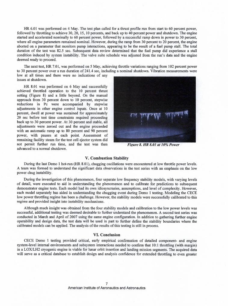
Figure 8. HR 8.01 at 10% Power
HR 6.01 was performed on 4 May. The test plan called for a thrust profile run from start to 60 percent power,followed by throttling to achieve 30, 20, 15, 10 percents, and back up to 40 percent power and shutdown. The enginestarted and accelerated nominally to 60 percent power, followed by a successful ramp down in power to 30 percent,where all engine parameters remained nominal. However, during the ramp from 30 percent to 20 percent, the engineaborted on a parameter that monitors pump interactions, appearing to be the result of a fuel pump stall. The totalduration of the test was 82.5 sec. Subsequent data review determined that the fuel pump did experience a stallcondition induced by system instability. The valve suite schedule was adjusted from the run's data and the enginedeemed ready to proceed.
The next test, HR 7.0 1, was performed on 5 May, achieving throttle variations ranging from 102 percent powerto 30 percent power over a run duration of 241.4 sec, including a nominal shutdown. Vibration measurements werelow at all times and there were no indications of anyissues at shutdown.
HR 8.01 was performed on 6 May and successfullyachieved throttled operation to the 10 percent thrustsetting (Figure 8) and a little beyond. On the manualapproach from 30 percent down to 10 percent, stepwisereductions in Pc were accompanied by stepwiseadjustments in other engine control inputs. Once at 10percent, dwell at power was sustained for approximately20 sec before test time constraints required proceedingback up to 30 percent power. At 30 percent and stable, alladjustments were zeroed out and the engine proceededwith an automatic ramp up to 80 percent and 90 percentpower, with pauses at each point. Assessment ofremaining facility steam for the test cell ejector system didnot permit further run time, and the test was thenadvanced to a normal shutdown.
V. Combustion StabilityDuring the last Demo 1 hot-run (HR 8.01), chugging oscillations were encountered at low throttle power levels.
A team was formed to understand the significant data observations in the test series with an emphasis on the lowpower chug instability.
During the investigation of this phenomenon, four separate low frequency stability models, with varying levelsof detail, were executed to aid in understanding the phenomenon and to calibrate for predictions to subsequentdemonstrator engine tests. Each model had its own idiosyncrasies, assumptions, and level of complexity. However,each model separately has aided in understanding the chugging event during Demo 1 testing. Modeling the CECElow power throttling regime has been a challenge. However, the stability models were successfully calibrated to thisregime and provided insight into instability mechanisms.
Although much insight was obtained from the four stability models and calibration to the low power levels wassuccessful, additional testing was deemed desirable to further understand the phenomenon. A second test series wasconducted in March and April of 2007 using the same engine configuration. In addition to gathering further engineoperability and design data, the test data will be used in part to further define the stability boundaries where thecalibrated models can be applied. The analysis of the results of this testing is still in process.
VI. ConclusionCECE Demo 1 testing provided critical, early empirical confirmation of detailed component- and engine
system-level internal environments and subsystem interactions needed to confirm that 10:1 throttling (with margin)in a LOX/LH2 cryogenic engine is viable for lunar orbit insertion and landing mission segments. The acquired datawill serve as a critical database to establish design and analysis confidence for extended throttling to even greater
American Institute of Aeronautics and Astronautics
levels if necessary for future and evolving Lunar Lander risk reduction development. Successes of the programinclude:
• A current production cryogenic engine was successfully modified to serve as a deep throttling testbedengine to explore technologies required for ongoing Lunar Lander risk reduction activities.
• Up to 11.4:1 throttling with stable operability was demonstrated in a LOX/LH2 engine in a space-relevantenvironment.
n Critical deep throttling operability data was acquired at the system and subsystem levels.
n Extensive performance data collected to understand the deep throttling engine operating environment forsubsequent design application in Phase H (Demonstrator Engine No. 2) and beyond (Lunar LanderDDT&E), including critically important detailed data of combustion instability at low power that must beeliminated in subsequent design activity (expected to be performed in Phase II, Option 2 of the CECEprogram).
Further analysis to better understand the combustion instability oscillations that were experienced in theDemonstrator Engine No. 1 tests at low power were conducted early in the subsequent Phase H, Option 1 programbegun in July 2006. The combustion instability must be clearly understood and eliminated in any future design anddemonstration activity prior to start of Lunar Lander DDT&E.
Also conducted under the Phase II, Option 1 program is a follow-on test of the Demo 1 engine (referred to asDemo 1.5) to explore additional engine operating modes of high value, including focused investigation of the chug(combustion instability) phenomena, expanding the envelope of thrust transient operation, and throttled thrustperformance impacts associated with mixture ratio excursions. The Demo 1.5 engine test began in late March 2007and the resulting data will be summarized in a final report.
AcknowledgmentsThe authors would like to thank the entire PWR and NASA team for the dedication and effort demonstrated
throughout the first twenty-four months of the CECE program.
References
1. "Advanced RL10 Engine for Manned Lunar Missions", PWR Internal Report PWA FR-388, 18 April 1962.2. "Discussion of the RL10 Engine Applied to Apollo Propulsion", PWR Internal Report PWA FR-918, 12
March 1964.3. Colbert, J. E., Mosier, S. A., and Bailey, T. E., "FLOX/Methane Pump-Fed Engine Study Final Report",
NASA CR-72485, 10 May 1969.4. Pugh, Richard L., "The Many Facets of the RL10 Liquid Rocket Engine ... A Continuing Success Story",
AIAA-98-3680, Technical Paper presented at 34th AIAA/ASME/SAE/ASEE Joint Propulsion Conference,13-15 July 1998.
8American Institute of Aeronautics and Astronautics